1
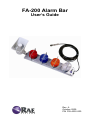
FA-200 Alarm Bar
User’s Guide
Rev. A
October 2009
P/N F05-4030-000
© Copyright 2009 RAE Systems, Inc
FA-200 Alarm Bar User’s Guide
Contents
1
2
3
4
5
6
7
8
9
Warnings............................................................................. 3
Standard Contents.............................................................. 4
General Information .......................................................... 4
2.1
Key Features..............................................................4
Physical Description.......................................................... 5
Installation ......................................................................... 5
4.1
Mounting the FA-200 Alarm Bar .............................. 5
4.2
Drilling Chart.............................................................6
4.3
Electrical/Control Connections ................................. 6
4.4
Connecting to An FMC2000 Controller.................... 7
4.5
Positioning The Siren Horn ....................................... 8
Maintenance ......................................................................8
Specifications ....................................................................9
Special Servicing Note ........................................................ 10
Troubleshooting............................................................... 11
7.1
Checking FMC2000 Relay Continuity....................12
Technical Support............................................................ 15
RAE Systems Contacts.................................................... 16
1
FA-200 Alarm Bar User’s Guide
Read Before Operating
This manual must be carefully read by all individuals who have
or will have the responsibility of using, maintaining, or
servicing this product. The product will perform as designed
only if it is used, maintained, and serviced in accordance with
the manufacturer’s instructions. The user should understand
how to set the correct parameters and interpret the obtained
results.
CAUTION!
To reduce the risk of electric shock, turn the power off before
opening this instrument or performing service. Never operate
the instrument when the instrument is open. Use and service
this product only in an area known to be non-hazardous.
2
FA-200 Alarm Bar User’s Guide
WARNINGS
Use only in non-hazardous locations.
For safety reasons, this equipment must be operated and
serviced by qualified personnel only. Read and understand
instruction manual completely before operating or servicing.
AVERTISSEMENT
Utiliser uniquement en zone non-dangereuse.
Pour des raisons de sécurité, cet équipment doit être utilisé,
entretenu et réparé uniquement par un personnel qualifié.
Étudier le manuel d’instructions en entier avant d’utiliser,
d’entretenir ou de réparer l’équipement.
3
FA-200 Alarm Bar User’s Guide
1 Standard Contents
•
•
•
FA-200 Alarm Bar
Integral 10-meter (33-foot) connection cable
User’s Guide
2 General Information
The FA-200 Alarm Bar works with RAE Systems FMC2000
controller and other compatible devices. It provides bright
visible and loud audible notification when a controller is in
alarm.
2.1
Key Features
• Loud siren: 112dB @ 3 m (10′)
• Four bright strobe lights with impact-resistant polycarbonate
lenses (red, white, blue, amber)
• Heavy-duty stainless-steel enclosure
• Stainless-steel bars to protect strobe lights
• Second port for interconnection with second controller
• Low maintenance
4
FA-200 Alarm Bar User’s Guide
3 Physical Description
The FA-200 Alarm Bar comes pre-assembled and requires
only connection via its integrated cord to a controller with
relays. It has mounting flanges at the top and bottom with
four holes that accept screws for attaching the FA-200
Alarm Bar to a wall or other flat surface. It receives all
power from the controller that it is attached to, simplifying
installation and maintenance.
4 Installation
4.1
Mounting the FA-200 Alarm Bar
The FA-200 Alarm Bar is designed to be wall-mounted and has
four holes for anchoring the FA-200 Alarm Bar, using screws or
bolts.
Before mounting the FA-200 Alarm Bar, make sure that its cord
can reach the controller that it will be electrically connected to.
Make sure that there is approximately 12" (30 cm) of clearance
on all sides of the FA-200 Alarm Bar so that the siren’s sound is
not attenuated and to ensure clear view of the four visible alarm
lights.
Follow these steps:
1. Locate the FA-200 Alarm Bar on a wall or other flat surface
and mark the four holes’ locations.
2. Remove the FA-200 Alarm Bar.
3. Drill the four holes.
5
FA-200 Alarm Bar User’s Guide
4. Hold the FA-200 Alarm Bar firmly against the wall and
insert and tighten the screws.
The FA-200 Alarm Bar is now ready to be connected to the
controller.
4.2
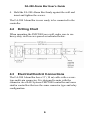
Drilling Chart
When mounting the FMC2000 on a wall, make sure to use
heavy-duty steel screws spaced as indicated below.
4.3
Electrical/Control Connections
The FA-200 Alarm Bar has a 33’ (10 m) cable with a screwtype multi-pin connector. It is designed to mate with the
connector on a RAE Systems FMC2000 controller and some
similar controllers that use the same connector type and relay
configuration.
6
FA-200 Alarm Bar User’s Guide
4.4
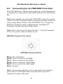
Connecting to An FMC2000 Controller
The FMC2000 has a female 6-pin connector on the bottom that
is designed for connection with a RAE Systems FA-200 Alarm
Bar.
Note: The internal wires from the FMC2000 connector are prewired to the NO (Normally Open) connection points on the five
relay wiring blocks. Refer to the FMC2000 User’s Guide for
details of wiring for other configurations, including NC
(normally closed) and other alarm orders.
Note: Pin F connects to Ground. Pins B, C, D, and E transmit
12V @ 2A power when an alarm occurs.
FMC2000 Connector Pin Layout
FMC2000 Connector Pinout
Pin A: No connection
Pin B: Power switch for red light
Pin C: Power switch for blue light
Pin D: Power switch for amber light
Pin E: Power switch for white light
Pin F: Ground
Note: If a second controller is not connected to the auxiliary
port on the FA-200 Alarm Bar, keep the dust cap on the
connector to protect the pins.
7
FA-200 Alarm Bar User’s Guide
4.5
Positioning The Siren Horn
If the FA-200 Alarm Bar is to be used outdoors or in other
environments where it may become wet, point the horn slightly
downward to allow drainage. This will prolong its life and
ensure its effectiveness.
5 Maintenance
No periodic maintenance is required for the FA-200 Alarm Bar.
Check occasionally that the cable is securely fastened and
shows no sign of damage. Also check that the polycarbonate
lenses are tightened on the bases of the strobe lights and have
no cracks. If they are damaged, they should be replaced.
8
FA-200 Alarm Bar User’s Guide
6 Specifications
Size
Weight
Enclosure
material
Audible alarm
Visual alarms
Flash rate
Primary Input
Secondary Input
Cable Length
Power Supply
Operating
Temperature
8" x 33" x 4.5"
(20.3 cm x 84 cm x 11.5 cm), including
siren horn
14.5 lbs (6.6 kg), excluding cable
Stainless steel with stainless steel
protection bars over each strobe light
112dB @ 3 m (10′)
Four super-bright xenon strobe lights
with polycarbonate lens covers (red,
white, blue, amber)
1 flash per second
Permanently affixed cable with 6-pin
male connector
6-pin male connector
33′ (10 m)
Powered by 12-volt 2A outputs from
controller
-40° F to +131° F (-40° C to +55° C)
9
FA-200 Alarm Bar User’s Guide
Special Servicing Note
If the instrument needs to be serviced, contact either:
The RAE Systems distributor from whom the instrument was
purchased; they will return the instrument on your behalf.
or
The RAE Systems Technical Service Department. Before
returning the instrument for service or repair, obtain a Returned
Material Authorization (RMA) number for proper tracking of
your equipment. This number needs to be on all documentation
and posted on the outside of the box in which the instrument is
returned for service or upgrade. Packages without RMA
Numbers will be refused at the factory.
10
FA-200 Alarm Bar User’s Guide
7
Troubleshooting
Problem
Possible Reasons & Solutions
Siren inoperative
Reasons:
Wiring problem.
Alarm level set too low at
controller.
Solutions:
Make sure cable is connected
to controller.
Make sure cable is not
damaged.
Check siren horn for
obstruction.
Test relay in controller.
Wiring problem.
Alarm level set too low at
controller.
Strobe light is damaged.
Strobe light
inoperative
Reasons:
Make sure cable is
connected to controller.
Make sure cable is not
damaged.
Check siren horn for
obstruction.
Test relay in controller.
Call Technical Support at +1
408-752-0723 or toll-free at
+1 888-723-4800
Relay wiring problem.
Solutions:
Wrong strobe
light during
alarm
Reasons:
Check that correct relay is
wired to appropriate strobe
light.
Reasons:
11
FA-200 Alarm Bar User’s Guide
7.1
Checking FMC2000 Relay Continuity
Each relay in an FMC2000 controller has a common terminal
and a normally open (NO) and normally closed (NC) terminal.
If you think the wiring to the FA-200 Alarm Bar is correct and
that the FA-200 Alarm Bar is in working order, but that an
alarm signal is not being passed to it, check the relays in the
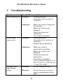
FMC2000 controller. Use a continuity tester or voltmeter (set to
measure resistance) to check the relay’s activity.
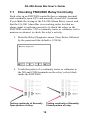
1. Enter the Relay Diagnostic menu. Press Enter, followed
by the password (the default is 123456).
2. Touch the probes of a continuity tester or voltmeter to
the NO and COM terminals on the relay’s relay block
inside the FMC2000.
Testing continuity of Normally
Open portion of relay.
Testing continuity of Normally
Closed portion of relay.
12
FA-200 Alarm Bar User’s Guide
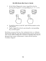
3. In the Relay Diagnostic menu, toggle the relay by
pressing the keypad’s corresponding key (1, 2, 3, 4. 5).
4. Touch the probes to the NC and COM terminals on the
relay block.
5. Again, toggle the relay by pressing the corresponding
key on the keypad.
Each time you press the key, the continuity tester or voltmeter
should show that the relay has changed from open to closed (or
vice versa). If this change does not occur, then the relay may be
damaged and require replacement. Contact RAE Systems
Customer Support.
13
FA-200 Alarm Bar User’s Guide
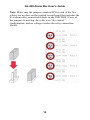
Note: Make sure the jumpers (marked JP for each of the five
relays) are in place on the printed circuit board that includes the
five alarm relay connection blocks in the FMC2000. If any of
the jumpers is missing, the relay is in “dry contact”
configuration, and no voltage reaches the relay connection
blocks.
14
FA-200 Alarm Bar User’s Guide
8
Technical Support
To contact RAE Systems Technical Support Team:
Monday through Friday, 7:00AM to 5:00PM Pacific (US) Time
Phone (toll-free): +1 888-723-4800
Phone: +1 408-952-8461
Email: [email protected]
Life-critical after-hours support is available:
+1 408-952-8200, select option 8
15
FA-200 Alarm Bar User’s Guide
9
RAE Systems Contacts
RAE Systems
World Headquarters
3775 N. First St.
San Jose, CA 95134-1708 USA
Phone: +1 408.952.8200
Fax: +1 408.952.8480
E-mail: [email protected]
Web Site: www.raesystems.com
RAE Systems Technical Support
Monday through Friday, 7:00AM to 5:00PM Pacific Time
Phone: +1.408.952.8461
Email: [email protected]
Life-critical after-hours support is available
+1.408.952.8200 select option 8
RAE Systems Europe ApS
Kirstinehøj 23 A
DK-2770 Kastrup
Denmark
Phone: +45 86 52 51 55
Fax:
+45 86 52 51 77
[email protected]
[email protected]
[email protected]
Web: www.raesystems.eu
16
FA-200 Alarm Bar User’s Guide
RAE Systems UK Ltd
D5 Culham Innovation Centre
Culham Science Centre
Abingdon, Oxon OX14 3DB
United Kingdom
Phone: +44 1865408368
Fax: +44 1235531119
Mobile: +44 7841362693
Email: [email protected]
RAE Systems France
336, rue de la fée des eaux
69390 Vernaison
France
Phone: +33 4 78 46 16 65
Fax: +33 4 78 46 25 98
Email: [email protected]
Web: www.raesystems.fr
RAE BeNeLux BV
Rijndal 20
2904 DC Capelle a/d IJssel
Phone: +31 10 4426149
Fax: +31 10 4426148
Email: [email protected]
Web: www.rae.nl
17
FA-200 Alarm Bar User’s Guide
RAE Systems Spain, s.l.
Av. Remolar, 31
08820 El Prat de Llobregat
Spain
Phone: +34 933 788 352
Fax: +34 933 788 353
Mobile: +34 687 491 106
Email: [email protected]
Web: www.raespain.com
RAE Systems Middle East
LOB 7, Ground Floor, Office 19
Jebel Ali Free Zone
Dubai, United Arab Emirates
Phone: +971.4.887.5562
Fax: +971.4.887.5563
RAE Systems (Hong Kong) Ltd.
Units 1516-18, 15/F, Delta House, 3 On Yiu Street
Shatin, NT, Hong Kong
Phone: +852.9.133.6225
Fax: +852.2.669.0803
Email: [email protected]
RAE Systems Japan
1-20-19-608 Higashinakajima Higashiyodogawa-ku
Osaka 533-0033, Japan
Phone: +81.6.6325.7660
Fax: +81.6.6325.7662
Email: [email protected]
18
FA-200 Alarm Bar User’s Guide
RAE Systems Korea
101-1301, Bucheon TechnoPark III, SamJungDong 36-1,
Oh Jung-Gu, Bucheon-Si, Gyeong Gi-Do
Korea 421-741
Phone: +82.32.624.0460
Fax: +82.32.624.0463
Email: [email protected]
19
RAE Systems
World Headquarters
3775 N. First St.
San Jose, CA 95134-1708 USA
Phone: 408.952.8200
Fax: 408.952.8480
E-mail: [email protected]
Web Site: www.raesystems.com
Rev. A
October 2009
P/N F05-4030-000