1
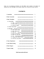
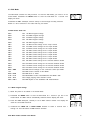
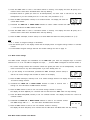
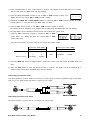
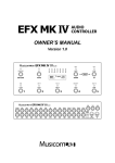
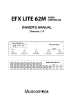
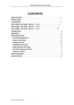
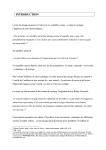
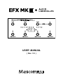
USER MANUAL ( Rev 1.0 ) Thank you for purchasing the Musicom Lab EFX MkIII+ Audio Controller. This Manual will introduce you to the EFX MkIII+ and its features. Make sure to keep this for future reference. CONTENTS 3 2. Basic Connection 4 3. Mode Description 5 5 3.1.1 Mute 5 3.1.2 Buffer ON/OFF Ground Lift ON/OFF 5 6 MIDI Program Change MIDI Control Change XPDL Port MIDI Receive Channel MIDI OUT / MIDI THRU Link Popping Noise Reduction Control Control the Pedal Switcher 7 1. Introduction 3.1 Preset Mode 3.1.3 3.2 Instant Access Mode 3.3 Edit Mode 3.3.1 3.3.2 3.3.3 3.3.4 3.3.5 3.3.6 3.3.7 3.3.8 6 7 8 9 11 11 12 12 13 4. Power Requirement 13 5. Initial Default Setting 14 6. Block Diagram 14 7. System Setting 15 http://www.musicomlab.com 1. Introduction The EFX MkIII+ Audio Controller is the ultimate floor-based switching system. It is a compact, easy to use, has 8 fully programmable loops, 4 function switches and a MIDI foot controller. The EFX Mk III+ Audio Controller has 240 memory locations, configured as 60 banks of 4 presets, plus a global preset. It can transmit 5 MIDI Program Change messages on 5 MIDI channels and 12 MIDI Control Change messages on an appointed MIDI channel. Also one continuous controller port(XPDL) is included and can be programmed with designated MIDI channels and controller numbers. The Master/Slave Mode allows one EFX MkIII+ to function as a master controller for a second slave EFX MkIII+ unit. The EFX Mk III+ Audio Controller has a low-noise, high quality buffer to prevent the loss of guitar signal. The input buffer can be bypassed for Hi-Z input pedals such as Fuzzes etc. The EFX Mk III+ Audio Controller is made of high quality parts, including heavy-duty stomp switches and gold-plated relays. It is cased within a compact and rugged aluminium enclosure(11"W x 5.2"D x 1.7"FH x 2.2"RH). Top Panel View Rear Panel View EFX MkIII+ Audio Controller User Manual 3 2. Basic Connection ྙ The loop send jacks(SND1 ~ SND8) and return jacks(RTN1 ~ RTN8) connect to the effects unit's inputs and outputs. ྚ The guitar connects to IN A jack, and amplifier input connects to OUT B jack. When the Hi-Z input pedal is in the loop, the buffer must be bypassed. Refer to page 5. ྛ The tuner connects to the TUNER jack. Refer to page 5. ྜ The channel control jacks connect to the FS1/FS2 and FS3/FS4 jacks when function switches are used for remote amplifier channel switching. For example: EFX MkIII+ Audio Controller User Manual 4 3. Mode Description The EFX Mk III+ Audio Controller utilizes three modes of operation: Preset Mode, Instant Access Mode and Edit Mode. On power-up, the display will show its firmware version, upon which bank 1(P.01 : Preset mode . Bank 1) and the global preset will be selected. 3.1 Preset Mode The EFX Mk III+ Audio Controller has 241 presets, configured as 60 banks of 4 presets, plus a global preset which is common to all banks. The Preset Mode is automatically selected when the power is initially turned on. ྙ Press/hold the BANK UP or BANK DOWN switches to scroll through the 60 available banks. ྚ The display will flash. ྛ The preset is selected via pressing any switches from PS-1 through PS-4. ྜ The display will stop flashing and the LED above the switch turn on. For example: to select the second preset of bank 3, press the BANK UP switch until the P.03 is shown on the display. And then press the PS-2 switch. The global preset is a preset with all the capabilities of preset 1 through 4, but is the same for all banks. Pressing the switch of a preset that is already on selects the global preset and will cause the LED above the switch to turn off. 3.1.1 Mute Press the MUTE switch to mute the output. When muted, the guitar signal flows into the TUNER jack and the three decimal points on the display will turn on and the output signal will be muted. Press the MUTE switch to cancel the mute function. The mute function is available in all modes. 3.1.2 Buffer On/Off When you connect Hi-Z stompboxes like a Fuzz into the Loop, the buffer must be bypassed. EFX MkIII+ Audio Controller User Manual 5 3.1.2 Groung Lift On/Off The 8 loops of the EFX MkIII+ Audio Controller make up 2 groups. One is Group A from IN A to Out A, the other is Group B from IN B to OUT B. The ground Lift switch is useful to prevent ground loop hum/noise when connecting a musical instrument to OUT A and IN B jacks. Refer to page 15~18. 3.2 Instant Access Mode (Programming the Loops and Function Switches) ྙ Select the preset to be programmed in the Preset Mode. ྚ Press the MODE switch to enter the Instant Access Mode. The display will show: And the 4 LEDs above the PS-1 ~ PS-4 switches will indicate the corresponding Loop1 ~ Loop4 as on or off. ྛ Press the PS-1 through PS-4 switches to turn the corresponding Loop1 ~ Loop4 on or off. The corresponding LEDs will go on or off. ྜ Press the MODE switch. The display will show: And the 4 LEDs above the PS-1 ~ PS-4 switches will indicate the corresponding Loop5 ~ Loop8 as on or off. ྜྷ Press the PS-1 through PS-4 switches to turn the corresponding Loop5 ~ Loop8 on or off. The corresponding LEDs will go on or off. ྞ Press the MODE switch. The display will show: And the 4 LEDs above the PS-1 ~ PS-4 switches will indicate the corresponding Function Switch1 ~ Function Switch4 as on or off. ྟ Press the PS-1 through PS-4 switches to turn the corresponding Function Switch 1 ~ Function Switch 4 on or off. The corresponding LEDs will go on or off. ྠ Press the BANK UP switch to store the edit and return to Preset Mode. For the other side, press the BANK DOWN switch to return to preset mode without storing the edit. ྡ Follow the same procedure ྙ~ྠ for any other presets you want to program for the loops and function switches. EFX MkIII+ Audio Controller User Manual 6 3.3 Edit Mode The Edit Mode contains the utility functions. To enter the Edit Mode, you must be in the Preset Mode. Press/hold the MODE switch to enter the Edit Mode for 1 second. The display will show: Press/hold the PS-1 switch(FS, function select) to scroll through the utility functions. Below is a list of functions in the order that they are shown. Function Select Order List PC.1 sets 1st MIDI Program Change PC.2 sets 2nd MIDI Program Change PC.3 sets 3rd MIDI Program Change PC.4 sets 4th MIDI Program Change PC.5 sets 5th MIDI Program Change LP.1 sets 1st MIDI Control Change for the Loop1 On/Off LP.2 sets 2nd MIDI Control Change for the Loop2 On/Off LP.3 sets 3rd MIDI Control Change for the Loop3 On/Off LP.4 sets 4th MIDI Control Change for the Loop4 On/Off LP.5 sets 5th MIDI Control Change for the Loop5 On/Off LP.6 sets 6th MIDI Control Change for the Loop6 On/Off LP.7 sets 7th MIDI Control Change for the Loop7 On/Off LP.8 sets 8th MIDI Control Change for the Loop8 On/Off FS.1 sets 9th MIDI Control Change for the Function Switch1 On/Off FS.2 sets 10th MIDI Control Change for the Function Switch2 On/Off FS.3 sets 11th MIDI Control Change for the Function Switch3 On/Off FS.4 sets 12th MIDI Control Change for the Function Switch4 On/Off EPL / ESW sets MIDI Control Change for the continuous control port XPDL r.ch sets MIDI receive channel of EFX MkIII+ M.ou / M.th sets MIDI OUT or THRU L.oF ~ L.dr sets Master/Slave mode or Send/Receive EFX MkIII+ data Pr.0 ~ Pr.4 sets 5-stage popping noise reduction control PS.F / PS.n sets MIDI SysEx for the VOODOO LAB Pedal Switcher 3.3.1 MIDI Program Change ྙ Select the preset to be edited in the Preset Mode ྚ Press/hold the MODE switch to enter the Edit Mode for 1 second if you are in the Preset Mode. The PC.1 will be automatically selected and the display will show: ྛ Press the PS-2 switch(CH, channel) to set a PC.1 channel number. The display will show the current PC.1 channel. ྜ Press/hold the BANK UP or BANK DOWN switches to select a channel from 1 through 16. The LED above the PS-2 switch will flash. EFX MkIII+ Audio Controller User Manual 7 ྜྷ Press the PS-2 switch to store a new PC.1 channel in memory. The display will show str (store) for a moment and the LED above the PS-2 switch will stop flashing. * The PC.x channel is global (the same for all banks/presets). You don't need to edit this for any other banks/presets if you have already done so. In this case, omit procedures ྛ~ྜྷ. ྞ Press the PS-3 switch(NUM, number) to set a PC.1 number. The display will show the current PC.1 number. ྟ Press/hold the BANK UP or BANK DOWN switches to select a PC.1 number from 001. through 128. or ---.. The LED above the PS-3 switch will flash. ྠ Press the PS-3 switch to store a new PC.1 number in memory. The display will show str (store) for a moment and the LED above the PS-3 switch will stop flashing. ྡ Press the PS-1 switch(FS, function select) to set other PC.x and follow the same procedure as ྛ~ྠ. Note * The ---. means no Program Change is transmitted. * The last decimal point on the display means that the display shows a Program Change number or controller number. * For initial default Program Change channels and number settings are refer to page 14. 3.3.2 MIDI Control Change The MIDI Control Changes are transmitted via the MIDI OUT jack when the assigned loops or function switches turn on or off. The LP.1 is assigned the Loop1, ... , and the FS.4 is assigned the Function Switch 4. * The Control Change channel and controller number are global (the same for all banks/presets). You don't need to edit these for any other banks/presets if you have already done so. ྙ If you are already in the Edit Mode, press/hold the PS-1 switch(FS, function select) to edit the 1st Control Change until the LP.1 is shown on the display. ྚ Press the PS-2 switch(CH, channel) to set a 1st Control Change channel. The display will show the current 1st Control Change channel. ྛ Press/hold the BANK UP or BANK DOWN switches to select a channel from 1 through 16. The LED above the PS-2 switch will flash. ྜ Press the PS-2 switch to store a new 1st Control Change channel in memory. The display will show str(store) for a moment and the LED above the PS-2 switch will stop flashing. ྜྷ Press the PS-3 switch(NUM, number) to set 1st controller number. The display will show the current 1st controller number. ྞ Press/hold the BANK UP or BANK DOWN switches to select a 1st controller number from 000. through 127. or ---.. The LED above the PS-3 switch will flash. ྟ Press the PS-3 switch to store a new 1st controller number in memory. The display will show str (store) for a moment and the LED above the PS-3 switch will stop flashing. EFX MkIII+ Audio Controller User Manual 8 ྠ The EFX MkIII+ has an additional reverse function that reverses the control value. Press the PS-4 switch(TGL, toggle) to reverse 1st control value. The display will show the current 1st control value mode, nor or rEv. The tables below show the control value and FS contact of the normal and reverse modes. Loop or FS turn on Loop or FS turn off nor (normal) 127 (0x7F) 0 (0x00) nor (normal) Normally - Open rEv (reverse) 0 (0x00) 127 (0x7F) rEv (reverse) Normally - Closed FS Contact ྡ Press the BANK UP switch to toggle between normal and reverse. The LED above the PS-4 switch will flash. ྡྷ Press the PS-4 switch to store the reverse function in memory. The display will show str (store) for a moment and the LED above the PS-4 switch will stop flashing. ྣ Follow the same procedure as ྙ~ྡྷ to set from 2nd MIDI Control Change through 12th MIDI Control Change. Note * The ---. means no Control Change is transmitted. * The nor means normal and the rEv means reverse. * The last decimal point on the display means that the display shows a Program Change number or controller number. * For initial default Control Change channels and controller numbers setting, refer to page 14. 3.3.3 XPDL Port The EFX Mk III+ Audio Controller contains a XPDL port for expression pedal input or external foot switch input. This can be used to alter parameters(via MIDI) in effects device that offer this capability. The MIDI Control Change Value is transmitted according to the position of expression pedal or external foot switch. Any passive volume or expression pedal can be used. Our recommended expression pedals are Boss FV500L and FV300L, and our recommended external foot switches are Boss FS-5U and FS-5L. * The EPL or ESW channel and number are global (the same for all banks/presets). you don't need to edit these for any other banks/presets if you have already done so. ྙ If you are already in the Edit Mode, press/hold the FS-1 switch(FS, function select) to edit the EPL or ESW for the XPDL port until the EPL or ESW is shown on the display. The display shows the EPL(Expression Pedal) when the expression pedal is connect to the XPDL jack. Otherwise, The display shows the ESW(External Foot Switch) when the external foot switch is connected or a plug is not connected to the XPDL jack. ྚ Press the PS-2 switch(CH, channel) to set an EPL or ESW channel. The display will show the EPL or ESW channel. ྛ Press/hold the BANK UP or BANK DOWN switches to select a channel from 1 through 16. The LED above the PS-2 switch will flash. EFX MkIII+ Audio Controller User Manual 9 ྜ Press the PS-2 switch to store a new channel in memory. The display will show str (store) for a moment and the LED above the PS-2 switch will stop flashing. ྜྷ Press the PS-3 switch(NUM, number) to set an EPL or ESW controller number. The display will show the current EPL or ESW controller number. ྞ Press/hold the BANK UP or BANK DOWN switches to select an EPL or ESW controller number from 000. through 127. or ---.. The LED above the PS-3 switch will flash. ྟ Press the PS-3 switch to store a new EPL or ESW controller number in memory. The display will show str (store) for a moment and the LED above the PS-3 switch will stop flashing. ྠ The EFX MkIII+ has an additional reverse function that reverses the control value. Press the PS-4 switch(TGL, toggle) to reverse an EPL or ESW control value. The display will show the current EPL or ESW control value mode. The table below shows the control value of the normal and reverse modes. Expression Pedal (EPL) Normal Reverse Minimum Position 0 (0x00) 127 (0x7F) Maximum Position 127 (0x7F) 0 (0x00) External Foot switch (ESW) Normal Reverse Open 0 (0x00) 127 (0x7F) Closed 127 (0x7F) 0 (0x00) ྡ Press the BANK UP switch to toggle between normal and reverse. The LED above the PS-4 switch will flash. ྡྷ Press the PS-4 switch to store the reverse function in memory. The display will show str(store) for a moment and the LED above the PS-4 switch will stop flashing. Cable Wiring for Expression Pedal The cable required is a stereo (TRS) to two mono 1/4" phone plugs. Connect the tip(stereo plug) to the pedal input, ring to the pedal output and sleeve to ground on all 3 plugs. Cable Wiring for External Foot Switch The cable required is a mono (TS) to a mono(TS) 1/4" phone plugs. EFX MkIII+ Audio Controller User Manual 10 Note * The ---. means no Control Change is transmitted. * The last decimal point on the display means that the display shows a Program Change number or controller number. * For initial default Control Change channels and controller numbers setting, refer to page 14. * Connect an expression pedal or an external foot switch to the XPDL jack before turing on the EFX MkIII+ Audio Controller. 3.3.4 MIDI Receive Channel The EFX MkIII+ can receive the MIDI Program Change and Control Change Message. The MIDI channel can be set to any individual channel from 1 to through 16, or reception can be turned off. ྙ If you are already in the Edit Mode, press/hold the FS-1 switch(FS, function select) to edit the MIDI receive channel until the r.ch is shown on the display. ྚ Press the PS-2 switch(CH, channel) to set a MIDI receive channel. The display will show the current MIDI receive channel. ྛ Press/hold the BANK UP or BANK DOWN switches to select a channel from 1 through 16 or C.--. The LED above the PS-2 switch will flash. ྜ Press the PS-2 switch to store a new channel in memory. The display will show str (store) for a moment and the LED above the PS-2 switch will stop flashing. Note * The c.--. means reception can be turned off. * The initial default setting is C.01. * For receiving the Program number refer to page 14. * Receiving Controller Number is the same as Transmitting Controller Number. 3.3.5 MIDI OUT / THRU The MIDI OUT connector of the EFX MkIII+ functions as a MIDI OUT or MIDI THRU. When MIDI OUT operation is selected, MIDI data in the EFX MkIII+ are transmtted via the MIDI OUT connector. And all Program Change and Control Change on the receive MIDI channel are not retransmitted. When MIDI THRU operation is selected, received MIDI data via the MIDI IN connector is retransmitted via the MIDI OUT connector. In this case, MIDI data in the EFX MkIII+ are not transmitted. ྙ if you are already in the Edit Mode, press/hold the FS-1 switch(FS, function select) until the M.ou or M.th is shown on the display. ྚ Press the BANK UP switch to select MIDI OUT or MIDI THRU. It will automatically be stored in memory when you return to Preset Mode. Note * The M.ou and M.th mean MIDI OUT and MIDI THRU. * The initial default setting is M.th. EFX MkIII+ Audio Controller User Manual 11 3.3.6 LINK Two EFX MkIII+'s can be setup to operate in a Master/Salve manner, allowing two EFX MkIII+'s to control the same rig from remote on-stage and off-stage locations. All MIDI and loop combination data in the slave EFX MkIII+ is ignored. In the Link data send/receive functions, you can copy all data from the Master EFX MkIII+ to the slave unit. Link Master/Slave Mode ྙ If you are already in the Edit Mode, press/hold the FS-1 switch(FS, function select) to select the master/slave mode until the L.oF, L.MA or LSL is shown on the display. ྚ Press the BANK UP switch to select L.oF, L.MA or L.SL. It will automatically be stored in memory when you return to Preset Mode. Note * The L.oF, L.MA and L.SL mean Link OFF, Link Master and Link Slave. * The initial default setting is L.oF. Link DATA Send/Receive ྙ If you are already in the Edit Mode, press/hold the FS-1 switch(FS, function select) of the slave EFXIII+ until the L.oF, L.MA or LSL is shown on the display. ྚ Press the BANK UP switch of the slave EFX MkIII+ to receive the data from master unit until the L.dr is shown on the display. ྛ if you are already in the Edit Mode, press/hold the FS-1 switch(FS, function select) of the master EFXIII+ until the L.oF, L.MA or LSL is shown on the display. ྜ Press the BANK UP switch of the master EFX MkIII+ to send the data to slave unit until the L.dS is shown on the display. The LED above the PS-4 switch will flash. ྜྷ Press the FS-4 switch of the master EFXIII+, The data from the master EFX MKIII+ will be transmitted to the slave unit. During the data sending/receiving, the display will flash. When the data sending/receiving is successful, the display will stop flashing. Note * The L.dS and L.dr mean Link DATA Send and Receive. 3.3.7 Popping Noise Reduction Control The EFX MkIII+ Audio Controller is based on relay switching. This method is utilized to route the audio signal with absolutely no tone coloration or degradation. The disadvantage of relays is that they can produce a slight popping noise when they switch on/off. The 5-stage popping noise reduction control is excellent for reducing this popping noise by muting time control of audio signal and switching order when the relays switch on/off. * The popping noise reduction control is global (the same for all banks/presets). You don't need to edit this for any other banks/presets if you have already done so. EFX MkIII+ Audio Controller User Manual 12 ྙ If you are already in the Edit Mode, press/hold the PS-1 switch(FS, function select) to set the popping noise reduction control until the Pr.2 is shown on the display. ྚ Press/hold the BANK UP switch to set a popping noise reduction control from Pr.0 through Pr.4. It will automatically be stored in memory when you return to Preset Mode. Pr0 means the popping noise reduction control is not used. Pr4 means the maximum of the popping noise reduction control. Note * The initial default setting is Pr.2. 3.3.8 Control the Pedal Switcher When you need more audio loops, you can use the Pedal Switcher of Voodoo Lab. The Pedal Switcher accepts only MIDI SysEx messages. The EFX MkIII+ can transmit these messages. ྙ If you are already in the Edit Mode, press/hold the PS-1 switch(FS, function select) to control the Pedal Switcher until the PS.F is shown on the display. ྚ Press the BANK UP switch to select PS.n. ྛ Press the MODE switch to store the function and return to Preset Mode. ྜ Select the preset to be programmed in the Preset Mode. ྜྷ Press the MODE switch to enter the Instant Access Mode. The display will show: And the 4 LEDs above PS-1 ~ PS-4 switches will indicate the corresponding Loop1 ~ Loop4 as on or off. ྞ Activate all the Pedal Switcher loops you want. ྟ Press the BANK UP switch to store the edit and return to Preset Mode, or press the BANK DOWN switch to return to Preset Mode without storing the edit. ྠ Follow the same procedure as ྜ~ྟ for any other presets you want to program into the Pedal Switcher. Note * The PS.F and PS.n mean Pedal Swither On and OFF. * The initial default setting is PS.F. * EFX MkIII+ can control 128 presets for the Pedal Switcher. (from bank 1preset 1 to bank 32preset 3 and global preset) 4. Power Requirements The EFX MkIII+ Audio Controller requires a regulated 12VDC or 9VAC at approximately 250mA. The power jack is a standard 5.5mm/2.1mm barrel. The EFX MkIII+ Audio Controller can also be powered from outputs 5 or 6 of the Voodoo Lab Pedal Power 2 Plus. You must set the corresponding DIP switch away from the normal position. EFX MkIII+ Audio Controller User Manual 13 5. Initial Default Setting The initial default setting for the EFX MkIII+ Audio Controller may be reset with the following procedure. This procedure will erase all user data from the EEPROM memory. Apply power while holding the MODE and PS-1 switches down. The display will show: At this moment, two switches can be released. When the initial default setting is successful, the EFX MkIII+ Audio Controller will automatically restart. Initial Default MIDI Transmit Setting Bank . Preset Global 1 . 1 1 . 2 1 . 3 1 . 4 32 . 3 32 . 4 33 . 1 33 . 2 60 . 4 PC1 NUM --1 2 3 4 1 127 128 ---- --- CH PC2 ~ PC5 CH NUM ----PC2 --: 2 --PC3 --: 3 --PC4 --: 4 --PC5 --: 5 --- Receiving Program Change number Map CCs / EPL CH NUM 1 --- Bank . Preset PC NUM Global 1 . 1 1 . 2 1 . 3 1 . 4 32 . 3 32 . 4 33 . 1 33 . 2 60 . 4 128 1 2 3 4 127 x x x x 6. Block Diagram EFX MkIII+ Audio Controller User Manual 14 7. System Example * Basic system * Input switched between two guitars EFX MkIII+ Audio Controller User Manual 15 * System with output switchable to either of two amplifiers being used * System with output switchable to either or both of two amplifiers being used EFX MkIII+ Audio Controller User Manual 16 * Chorus / Delay patch change via MIDI PCs * Chorus / Delay patch and On/OFF change via MIDI PCs and CCs EFX MkIII+ Audio Controller User Manual 17 * Rack system with Mixer * Link Master / Slave EFX MkIII+ Audio Controller User Manual 18