1
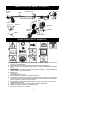
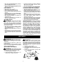
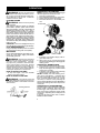
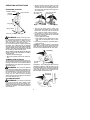
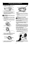
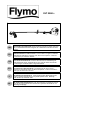
XLT 2000+
GB
FR
DE
ES
IT
NL
INSTRUCTION MANUAL
IMPORTANT INFORMATION: Please read these instructions carefully and make
sure you understand them before using this unit. Retain these instructions for future
reference.
MANUEL D’INSTRUCTIONS
RENSEIGNEMENTS IMPORTANTS: Avant d’utiliser cet appareil, veuillez lire
atentivement les instructions et assurez--vous de les avoir comprises. Conservez
les instructions pour référence ultérieure.
BETRIEBSANWEISUNG
WICHTIGE INFORMATION: Lesen Sie diese Hinweise zur Handhabung des
Geräts aufmerksam durch. Verwenden Sie es erst, wenn Sie sicher sind, daß Sie
alle Anweisungen verstanden haben und gut aufbewahren.
MANUAL DE INSTRUCCIONES
INFORMACIÓN IMPORTANTE: Lea atentamente las instrucciones y
asegúrese de entenderlas antes de utilizar esta aparato. Conserve las instrucciones para la referencia en el futuro.
LIBRETTO D’ISTRUZIONI
INFORMAZIONI IMPORTANTI: Siete pregati di leggere attentamente questo
istruzioni e prendere dimestichezza con il prodotto prima di usario. Mantenga
queste istruzioni per riferimento futuro.
HANDLEIDING
BELANGRIJKE IMPORTANTS: Lees deze instructies zorgvuldig en wees er
zeker van dat uze begrijpt alvorens de trimmer te gebruiken en bewaar ze voor
toekomstige raadpleging.
IDENTIFICATION (WHAT IS WHAT?)
Muffler
Trimmer
head
Shaft
Assist handle
Assist handle adjustment
Primer
Bulb
Throttle
Shield
Manual
Start lever
ON/OFF
switch
Fuel tank
Wrench
Starter handle
IDENTIFICATION OF SYMBOLS
A.
B.
C.
D.
E.
F.
G.
H.
I.
J.
K.
L.
WARNING! This trimmer can be dangerous! Careless or improper use can cause
serious or even fatal injury.
Read and understand the instruction manual before using the trimmer.
With this handle, only use trimmer head. Never use blades or flailing devices with this
tool.
WARNING! The trimmer line can throw objects violently. You can be blinded or
injured. Always wear eye protection.
Always use:
Ear protection
Protective glasses or visor
Assist handle to be positioned only below the arrow.
The operator of the machine must insure that no one comes within a 15 meter radius
while working. When several operators are working within the same area a safety distance of at least 15 meters must be observed.
Use unleaded or quality leaded petrol and two--stroke oil mixed at a ratio of 2.5%.
Engine ON/OFF Switch.
Guaranteed sound power level according to Directive 2000/14/EC
Maximum rotational frequency of the spindle, rpm
Sound pressure level at 7,5 meters
2
SAFETY RULES
WARNING:
When using gardening
appliances, basic safety precautions should always be followed to reduce the risk of fire and
serious injury. Read and follow all instructions.
This power unit can be dangerous! Operator is
responsible for following instructions and warnings on unit and in manual. Read entire instruction manual before using unit! Be thoroughly familiar with the controls and the proper use of the
unit. Restrict the use of this unit to persons who
read, understand, and follow instructions and
warnings on unit and in manual. Never allow
children to operate this unit.
INSTRUCTION
MANUAL
SAFETY INFORMATION
ON THE UNIT
DANGER: Never use blades, wire, or
flailing devices. This unit is designed for line
trimmer use only. Use of any other accessories
or attachments will increase the risk of injury.
WARNING: Trimmer line throws objects violently. You and others can be blinded/
injured. Wear safety glasses and leg protection. Keep body parts clear of rotating line.
S Dress properly.
Always wear safety
glasses or similar eye protection when operating, or performing maintenance, on
your unit (safety glasses are available).
Eye protection should be marked Z87.
S Always wear face or dust mask if operation
is dusty.
S Always wear heavy, long pants, long
sleeves, boots, and gloves. Wearing safety
leg guards is recommended.
S Always wear foot protection. Do not go
barefoot or wear sandals. Stay clear of
spinning line.
S Secure hair above shoulder length. Secure
or remove loose clothing or clothing with
loosely hanging ties, straps, tassels, etc.
They can be caught in moving parts.
S Being fully covered also helps protect you
from debris and pieces of toxic plants
thrown by spinning line.
S Stay Alert. Do not operate this unit when you
are tired, ill, upset or under the influence of alcohol, drugs, or medication. Watch what you
are doing; use common sense.
S Wear hearing protection.
S Mufflers fitted with catalytic converters get
very hot during use and remain so for some
time after stopping. This also applies at idle
speed. Contact can result in burns to the skin.
Remember the risk of fire!
S Mufflers fitted with catalytic converters get
very hot during use and remain so for some
time after stopping. This also applies at idle
speed. Contact can result in burns to the skin.
Remember the risk of fire!
S Never start or run inside a closed room or
building. Breathing exhaust fumes can kill.
S Keep handles free of oil and fuel.
UNIT / MAINTENANCE SAFETY
Keep children, bystanders, and animals 15 meters away. If approached stop unit immediately.
If situations occur which are not covered in
this manual, use care and good judgement. If
you need assistance, contact your authorized
service dealer.
OPERATOR SAFETY
WARNING: This machine produces
an electromagnetic field during operation. Under
some circumstances, this field may interfere
with active or passive medical implants. To reduce the risk of serious or fatal injury, we recommend persons with medical implants to consult
their physician and the medical implant
manufacturer before operating this machine.
S Disconnect the spark plug before performing
maintenance except carburetor adjustments.
S Look for and replace damaged or loose
parts before each use. Look for and repair
fuel leaks before use. Keep in good working
condition.
S Replace trimmer head parts that are
chipped, cracked, broken, or damaged in
any other way before using the unit.
S Maintain unit according to recommended procedures. Keep cutting line at proper length.
S Use only 2 mm diameter Flymo brand line.
Never use wire, rope, string, etc.
S Install required shield properly before using
the unit. Use only specified trimmer head;
make sure it is properly installed and securely fastened.
S Make sure unit is assembled correctly as
shown in this manual.
S Make carburetor adjustments with lower
end supported to prevent line from contacting any object.
S Keep others away when making carburetor
adjustments.
3
S Use only recommended Flymo accessories and replacement parts.
S Have all maintenance and service not explained in this manual performed by an authorized service dealer.
FUEL SAFETY
S
S
S
S
S
S
S
S
Mix and pour fuel outdoors.
Keep away from sparks or flames.
Use a container approved for fuel.
Do not smoke or allow smoking near fuel or
the unit.
Avoid spilling fuel or oil. Wipe up all fuel spills.
Move at least 3 meters away from fueling
site before starting engine.
Stop engine and allow to cool before removing fuel cap.
Always store gasoline in a container approved for flammable liquids.
CUTTING SAFETY
WARNING: Inspect the area before
each use. Remove objects (rocks, broken
glass, nails, wire, etc.) which can be thrown
by or become entangled in line. Hard objects
can damage the trimmer head and be thrown
causing serious injury.
S Use only for trimming, scalping, mowing
and sweeping. Do not use for edging, pruning or hedge trimming.
S Keep firm footing and balance. Do not overreach.
S Keep all parts of your body away from muffler and spinning line. Keep engine below
waist level. A hot muffler can cause serious
burns.
S Cut from your left to your right. Cutting on
right side of the shield will throw debris
away from the operator.
S Use only in daylight or good artificial light.
S Use only for jobs explained in this manual.
TRANSPORTING AND STORAGE
S Allow the engine to cool; secure unit before
storing or transporting in vehicle.
S Empty fuel tank before storing or transporting the unit. Use up fuel left in the carburetor
by starting engine and letting it run until it
stops.
S Store unit and fuel in an area where fuel vapors cannot reach sparks or open flames
from water heaters, electric motors or
switches, furnaces, etc.
S Store unit so line limiter cannot accidentally
cause injury. Unit can be hung by the shaft.
S Store the unit out of the reach of children.
S Secure the machine during transport.
SPECIAL NOTICE: Exposure to vibrations
through prolonged use of gasoline powered
hand tools could cause blood vessel or nerve
damage in the fingers, hands, and joints of
people prone to circulation disorders or abnormal swellings. Prolonged use in cold weather
has been linked to blood vessel damage in
otherwise healthy people. If symptoms occur
such as numbness, pain, loss of strength,
change in skin color or texture, or loss of feeling
in the fingers, hands, or joints, discontinue the
use of this tool and seek medical attention. An
anti-vibration system does not guarantee the
avoidance of these problems. Users who operate power tools on a continual and regular basis
must monitor closely their physical condition
and the condition of this tool.
ASSEMBLY
WARNING: Make sure unit is proper-
ly assembled and all fasteners are secure.
Examine parts for damage. Do not use damaged parts.
It is normal for the fuel filter to rattle in the
empty fuel tank.
Finding fuel or oil residue on muffler is normal
due to carburetor adjustments and testing
done by the manufacturer.
ADJUSTING THE HANDLE
WARNING: When adjusting the assist
handle, be sure it remains above the safety label
and below the mark or arrow on the shaft.
1. Loosen wing nut on handle.
2. Rotate the handle on the shaft to an upright position; retighten wing nut.
ATTACHING THE SHIELD
WARNING: The shield must be properly installed. The shield provides partial
protection from the risk of thrown objects to
the operator and others and is equipped with
a line limiter which cuts excess line. The line
limiter (on underside of shield) is sharp and
can cut you.
1. Remove nut from shield.
2. Insert bracket into slot on shield.
3. Pivot shield until bolt passes through hole
in bracket.
4. Reinstall nut and tighten securely with
wrench (provided).
Bracket
Slot
Nut
PIVOT
4
Gearbox
Shield
OPERATION
WARNING: Be sure to read the fuel
information in the safety rules before you begin. If you do not understand the safety rules,
do not attempt to fuel your unit. Contact an
authorized service dealer.
FUELING ENGINE
WARNING: Remove fuel cap slowly
when refueling.
This engine is certified to operate on unleaded
petrol. Before operation, petrol must be mixed
with a good quality 2--cycle air--cooled engine oil
designed to be mixed at a ratio of 40:1. A 40:1
ratio is obtained by mixing 5 liters of unleaded
petrol with 0,125 liter of oil. DO NOT USE automotive oil or marine oil. These oils will cause engine damage. When mixing fuel, follow instructions printed on oil container. Once oil is added
to petrol, shake container momentarily to assure
that the fuel is thoroughly mixed. Always read
and follow the safety rules relating to fuel before
fueling your unit.
CAUTION: Never use straight petrol in your
unit. This will cause permanent engine damage.
STARTING A COLD ENGINE
NOTE: DO NOT squeeze the throttle trigger
until the engine has started and runs.
1. Set unit on a flat surface.
2. Move ON/OFF switch to the ON position.
3. Slowly press the primer bulb 6 times.
4. Move the start lever to the START position.
Primer Bulb
Start
Lever
FUEL REQUIREMENTS
Use good quality unleaded petrol. The lowest
recommended octane grade is 90 (RON).
IMPORTANT
Use of alcohol blended fuels (more than 10% alcohol) can cause major engine performance
and durability problems.
WARNING: Incorrect use of fuel and/
or lubricants will cause problems such as:
improper clutch engagements, overheating, vapor lock, power loss, lubrication deficiency, deterioration of fuel lines, gaskets
and internal carburetor components, etc.
Alcohol blended fuels will cause a high absorption of moisture in the fuel/oil mixture,
causing the separation of oil and fuel.
HOW TO STOP YOUR UNIT
S To stop the engine, move the ON/OFF
switch to the OFF position.
HOW TO START YOUR UNIT
WARNING: The trimmer head will
turn while starting the engine. Avoid any contact with the muffler. A hot muffler can cause
serious burns.
Starter Handle
5. Pull starter rope handle sharply until engine starts and runs.
6. Allow unit to run for 10 seconds, then fully
squeeze the throttle trigger to disengage the
starting system.
STARTING A WARM ENGINE
1. Move ON/OFF switch to the ON position.
2. Squeeze and hold the throttle trigger.
Keep throttle trigger fully squeezed until
engine runs smoothly.
3. Pull starter rope sharply while squeezing
throttle trigger until engine runs.
NOTE: Normally, the warm starting procedure can be used within 5 -- 10 minutes after
the unit is turned OFF. If the unit sits for more
than 10 minutes without being run, it will be
necessary to start the unit by following the
steps under STARTING A COLD ENGINE or
following the starting instruction steps shown
on the unit.
STARTING A FLOODED ENGINE
Starting Position
Flooded engines can be started by pulling the
starter handle repeatedly while squeezing
throttle trigger until engine starts and runs.
This could require pulling the starter handle
many times, depending on how badly the unit
is flooded.
If the unit still doesn’t start, refer to TROUBLESHOOTING TABLE.
5
OPERATING INSTRUCTIONS
OPERATING POSITION
ALWAYS WEAR:
Hearing
protection
S The tip of the line does the cutting. You will
achieve the best performance and minimum line wear by not crowding the line into
the cutting area. The right and wrong ways
are shown below.
Tip of line does
the cutting.
Eye protection
Long pants
Heavy shoes
Cut from your left to your right.
WARNING: Always wear eye protection and hearing protection. Never lean over
the trimmer head. Rocks or debris can ricochet or be thrown into eyes and face and
cause blindness or other serious injury.
Do not run the engine at a higher speed than
necessary. The cutting line will cut efficiently
when the engine is run at less than full throttle.
At lower speeds, there is less engine noise and
vibration. The cutting line will last longer and will
be less likely to “weld” onto the spool.
Always release the throttle trigger and allow the
engine to return to idle speed when not cutting.
To stop engine:
S Release the throttle trigger.
S Move the ON/OFF switch to the OFF position.
Line crowded into
work area.
Right
Wrong
S The line will easily remove grass and
weeds from around walls, fences, trees and
flower beds, but it also can cut the tender
bark of trees or shrubs and scar fences.
S For trimming or scalping, use less than full
throttle to increase line life and decrease
head wear, especially:
S During light duty cutting.
S Near objects around which the line canwrap such as small posts, trees or fence
wire.
S For mowing or sweeping, use full throttle for
a good clean job.
TRIMMING -- Hold the bottom of the trimmer
head about 8 cm above the ground and at an
angle. Allow only the tip of the line to make contact. Do not force trimmer line into work area.
Trimming
TRIMMER LINE ADVANCE
Advance line by tapping the bottom of the cutting head lightly on the ground while engine is
running at full speed. The metal line limiter
blade attached to the guard will cut the line to
the proper length.
WARNING: Use only 2 mm diameter
line. Other sizes and shapes of line will not advance properly and will result in improper cutting head function or can cause serious injury.
Do not use other materials such as wire,
string, rope, etc. Wire can break off during
cutting and become a dangerous missile that
can cause serious injury.
8 cm above
ground
SCALPING -- The scalping technique removes
unwanted vegetation. Hold the bottom of the
trimmer head about 8 cm above the ground and
at an angle. Allow the tip of the line to strike the
ground around trees, posts, monuments, etc.
This technique increases line wear.
CUTTING METHODS
WARNING: Use minimum speed and
do not crowd the line when cutting around
hard objects (rock, gravel, fence posts, etc.),
which can damage the trimmer head, become
entangled in the line, or be thrown causing a
serious hazard.
6
MOWING -- Your trimmer is ideal for mowing
in places conventional lawn mowers cannot
reach. In the mowing position, keep the line
parallel to the ground. Avoid pressing the
head into the ground as this can scalp the
ground and damage the tool.
SWEEPING -- The fanning action of the rotating line can be used for a quick and easy
clean up. Keep the line parallel to and above
the surfaces being swept and move the tool
from side to side.
Mowing
MAINTENANCE
WARNING:
Disconnect the spark
plug before performing maintenance except
for carburetor adjustments.
CHECK FOR LOOSE
FASTENERS AND PARTS
S
S
S
S
S
Spark Plug Boot
Air Filter
Housing Screws
Assist Handle Screw
Debris Shield
1. Clean the cover and the area around it to
keep dirt from falling into the carburetor
chamber when the cover is removed.
2. Remove parts as illustrated.
NOTE: Do not clean filter in gasoline or other
flammable solvent to avoid creating a fire hazard or producing harmful evaporative emissions.
3. Wash the filter in soap and water.
4. Allow filter to dry.
5. Replace parts.
CHECK FOR DAMAGED OR
WORN PARTS
Button
Contact an authorized service dealer for replacement of damaged or worn parts.
S ON/OFF Switch -- Ensure ON/OFF switch
functions properly by moving the switch to
the OFF position. Make sure engine stops;
then restart engine and continue.
S Fuel Tank -- Discontinue use of unit if fuel
tank shows signs of damage or leaks.
S Debris Shield -- Discontinue use of unit if
debris shield is damaged.
INSPECT AND CLEAN UNIT AND
LABELS
S After each use, inspect complete unit for
loose or damaged parts. Clean the unit and
labels using a damp cloth with a mild detergent.
S Wipe off unit with a clean dry cloth.
CLEAN AIR FILTER
A dirty air filter decreases engine performance and increases fuel consumption and
harmful emissions. Always clean after every
5 hours of operation.
Air Filter
Air Filter Cover
REPLACE SPARK PLUG
Replace the spark plug each year to ensure
the engine starts easier and runs better. Set
spark plug gap at 0,6 mm. Ignition timing is
fixed and nonadjustable.
1. Twist, then pull off spark plug boot.
2. Remove spark plug from cylinder and discard.
3. Replace with Champion RCJ-6Y spark
plug and tighten securely with a 19 mm
socket wrench.
4. Reinstall the spark plug boot.
7
SERVICE AND ADJUSTMENTS
REPLACING THE LINE
1. Press the tabs on the side of the trimmer
head and remove cover and spool.
Spool
Cover
Tab
Tap Button
2. Remove any remaining line.
3. Clean dirt and debris from all parts. Replace spool if it is worn or damaged.
4. Replace with a pre-wound spool, or replace line using a 8 meters length of 2 mm
diameter Flymo brand line.
WARNING: Never use wire, rope,
string, etc., which can break off and become a
dangerous missile.
5. When installing new line on an existing
spool, hold the spool as shown in the illustration below.
6. Bend the line at the midpoint and insert
the bend into the slot in the center rim of
the spool. Ensure line snaps into position
in the slot.
Slot
Spool
Cover
11. Make sure the lines are not caught between the rim of the spool and the wall of
the cover.
12. Reinstall the spool and cover onto the
trimmer head. Push until cover snaps into
place.
CARBURETOR ADJUSTMENT
WARNING: Keep others away when
making idle speed adjustments. The trimmer
head will be spinning during this procedure.
Wear your protective equipment and observe
all safety precautions.
The carburetor has been carefully set at the
factory. Adjustments may be necessary if you
notice any of the following conditions:
S Engine will not idle when the throttle is released.
Make adjustments with the unit supported so
the cutting attachment is off the ground and
will not make contact with any object. Hold
the unit by hand while running and making adjustments. Keep all parts of your body away
from the cutting attachment and muffler.
Idle Speed Adjustment
7. With your finger between the lines, wrap
the lines evenly and firmly around the
spool in a clockwise direction.
8. Position the lines in the guide slots.
Allow engine to idle. Adjust speed until engine
runs without stalling (idle speed too slow).
S Turn idle speed screw clockwise to increase engine speed if engine stalls or dies.
S Turn idle speed screw counterclockwise to
decrease engine speed.
Idle Speed Screw
Guide Slot
Guide
Slot
Air Filter Cover
9. Insert the ends of the lines through exit
holes in the sides of the cover.
10. Place the spool in the cover.
If you require further assistance or are unsure
about performing this procedure, contact an
authorized service dealer.
8
STORAGE
WARNING:
Perform the following
steps after each use:
S Allow engine to cool before storing or transporting.
S Store unit and fuel in a well ventilated area
where fuel vapors cannot reach sparks or
open flames from water heaters, electric
motors or switches, furnaces, etc.
S Empty fuel tank before storing or transporting the unit.
S Store unit and fuel well out of the reach of
children.
S Store unit with all guards in place. Position
unit so that any sharp object cannot accidentally cause injury.
SEASONAL STORAGE
Prepare unit for storage at end of season or if
it will not be used for 30 days or more.
If your unit is to be stored for a period of time:
S Clean the entire unit before lengthy storage.
S Store in a clean dry area.
S Lightly oil external metal surfaces.
ENGINE
S Remove spark plug and pour 1 teaspoon of
40:1, 2-cycle engine oil (air cooled) through
the spark plug opening. Slowly pull the
starter rope 8 to 10 times to distribute oil.
S Replace spark plug with new one of recommended type and heat range.
S Clean air filter.
S Check entire unit for loose screws, nuts,
and bolts. Replace any damaged, broken,
or worn parts.
S At the beginning of the next season, use
only fresh fuel having the proper gasoline to
oil ratio.
OTHER
S Do not store gasoline from one season to
another.
S Replace your gasoline can if it starts to rust.
9
TROUBLESHOOTING TABLE
WARNING: Always stop unit and disconnect spark plug before performing all of the
recommended remedies below except remedies that require operation of the unit.
TROUBLE
CAUSE
REMEDY
Engine will not
start.
1. ON/OFF switch in OFF
position.
2. Engine flooded.
1. Move ON/OFF switch to ON position.
3. Fuel tank empty.
4. Spark plug not firing.
5. Fuel not reaching
carburetor.
Engine will
not idle
properly.
Engine will not
accelerate,
lacks power,
or dies under
a load.
Engine
smokes
excessively.
Engine runs
hot.
6. Carburetor requires
adjustment.
1. Carburetor requires
adjustment.
2. Crankshaft seals worn.
3. Compression low.
1. Air filter dirty.
2. Spark plug fouled.
3. Carburetor requires
adjustment.
4. Carbon build-up on
muffler outlet screen.
5. Compression low.
1. Fuel mixture incorrect.
2. Air filter dirty.
3. Carburetor requires
adjustment.
1. Fuel mixture incorrect.
2. Spark plug incorrect.
3. Carburetor requires
adjustment.
4. Carbon build-up on
muffler outlet screen.
2. See “Starting a Flooded Engine” in
Operation Section.
3. Fill tank with correct fuel mixture.
4. Install new spark plug.
5. Check for dirty fuel filter; replace.
Check for kinked or split fuel line;
repair or replace.
6. Contact an authorized service dealer.
1. See “Carburetor Adjustment” in
Service and Adjustments Section.
2. Contact an authorized service dealer.
3. Contact an authorized service dealer.
1. Clean or replace air filter.
2. Clean or replace plug
and regap.
3. Contact an authorized service dealer.
4. Contact an authorized service dealer.
5. Contact an authorized service dealer.
1. Empty fuel tank and refill with
correct fuel mixture.
2. Clean or replace air filter.
3. Contact an authorized service dealer.
1. Empty fuel tank and refill with
correct fuel mixture.
2. Replace with correct spark plug.
3. Contact an authorized service dealer.
4. Contact an authorized service dealer.
10
DECLARATION OF CONFORMITY
EC Declaration of Conformity (Only applies to Europe)
We, Husqvarna AB, SE-561 82 Huskvarna, Sweden, tel: +46--36--146500, as authorised
representative in the Community, declare that the grass trimmer model Flymo XLT 2000+
with serial numbers dating from 2009 and onwards (the year is clearly stated on the rating
plate, followed by the serial number), comply with the requirements of the COUNCIL’S
DIRECTIVES:
of 17 May 2006 “relating to machinery” 2006/42/EC;
of 15 December 2004 “relating to electromagnetic compatibility” 2004/108/EC, and applicable
supplements; and
of 8 May 2000 “relating to the noise emissions in the environment” in accordance with Annex
V of 2000/14/EC. For information relating to noise emissions, see Technical data section.
The following standards have been applied: EN ISO 12100-- 1/A1:2009, EN ISO
12100-- 2/A1:2009, CISPR 12:2007, EN 11806:2008.
SMP Svensk Maskinprovning AB, Fyrisborgsgatan 3, S--754 50 Uppsala, Sweden, has
performed voluntary type examination on behalf of Husqvarna AB. The certificate(s) are
numbered: SEC/09/2018.
09--11--01
Ronnie E. Goldman, Director of Engineering
Authorized representative for Husqvarna AB and
responsible for technical documentation
11
TECHNICAL DATA SHEET
MODEL: XLT 2000+
ENGINE
25
Cylinder displacement, cm3
At maximum engine power, rpm
8000
Maximum rotational frequency of the spindle, rpm
10000
Engine speed at recommended maximum spindle
rotational frequency, rpm
7400
Recommended speed idling, rpm
4000
Maximum engine power, measured in
accordance with ISO 8893, kW
0,7
Catalytic converter muffler
Yes
IGNITION SYSTEM
Spark plug
Champion RCJ--6Y
Electrode gap, mm
0,6
FUEL AND LUBRICATION SYSTEM
340
Fuel tank volume capacity, cm3
Fuel consumption at maximum engine power,
measured in accordance with ISO 8893, g/h
407
Specified fuel consumption at max. engine power,
measured in accordance with ISO 8893, g/kWh
768
WEIGHT
Weight without fuel, cutting attachment and guard, kg
4,6
NOISE EMISSIONS
(see Note 1)
Sound power level, measured dB(A)
108
112
Sound power level, guaranteed LWA dB(A)
SOUND LEVELS
(see Note 2)
Equivalent sound pressure level at the operator’s ear, measured
according to EN ISO 11806 and ISO 22868, dB(A)
Equipped with trimmer head (original)
100,4
VIBRATION LEVELS
(see Note 3)
Equivalent vibration levels (ahv,eq) at handles, measured
according to EN ISO 11806 and ISO 22867, m/s2
Equipped with trimmer head (original), left/right
3,0/8,7
Note 1: Noise emissions in the environment measured as sound power (LWA) in conformity
with EC directive 2000/14/EC. Reported sound power level for the machine has been
measured with the original cutting attachment that gives the highest level. The difference
between guaranteed and measured sound power is that the guaranteed sound power also
includes dispersion in the measurement result and the variations between different machines
of the same model according to Directive 2000/14/EC.
Note 2: Reported data for equivalent sound pressure level for the machine has a typical
statistical dispersion (standard deviation) of 1 dB(A).
Note 3: Reported data for equivalent vibration level has a typical statistical dispersion
(standard deviation) of 1 m/s2.
Model XLT 2000+ (3/8 LH arbor shaft thread)
Approved accessories
Type
Trimmer head
TNG7 (∅ 2 mm line) 537419207 / 530071997
Cutting attachment / guard, part. no.
12