1
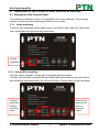
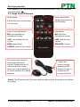
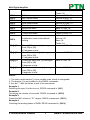
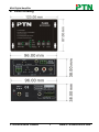
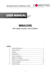
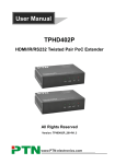
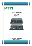
Mini Digital Amplifier USER MANUAL PA2B PTN Mini Digital Amplifier Version: PA2B2013V1.2 PTN Electronics Limited www.PTN-electronics.com Mini Digital Amplifier NOTICE: Please read this user manual carefully before using this product. This manual is for operation instruction only, not for any maintenance usage. The functions described in this version are updated till January 2013. Any changes of functions and parameters since then will be informed separately. Please refer to the dealers for the latest details. This manual is copyright PTN Electronics Limited. All rights reserved. No part of this publication may be copied or reproduced without the prior written consent of PTN Electronics Limited. All product function is valid till 2013-01-07. Update History Version 1.0 1.1 1.2 Date 2012.12.25 2012.12.28 2013.01.07 PTN Electronics Limited Update Content First version. Update the pictures related to the IR remote. Modified some operation commands. www.PTN-electronics.com Mini Digital Amplifier Table of Contents 1. Introduction .............................................................................................................. 1 1.1. Introduction to PA2B ........................................................................................ 1 1.2. Package Contents ........................................................................................... 1 2. Features ................................................................................................................... 1 3. Specification ............................................................................................................. 2 4. System Connection Introduction .............................................................................. 2 4.1. Audio Output .................................................................................................... 2 4.1.1. Default output: 2x20Watt@4Ohm ......................................................... 2 4.1.2. Bridge connection: 1x40Watt@8Ohm .................................................. 3 4.1.3. Dual-mono Output ................................................................................ 3 4.2. Microphone input ............................................................................................. 4 4.2.1. 48V phantom power input..................................................................... 4 4.2.2. MIC input .............................................................................................. 4 4.2.3. LINE input............................................................................................. 4 5. Operation of the Control Panel and the IR Remote .................................................. 5 5.1. Operation of the Control Panel ........................................................................ 5 5.1.1. Audio switching .................................................................................... 5 5.1.2. Volume/EQ controlling .......................................................................... 5 5.2. Usage of the IR Remote .................................................................................. 6 6. System Diagram....................................................................................................... 7 7. Communication Protocol and Command Codes ...................................................... 7 8. Panel Drawing .......................................................................................................... 9 9. Troubleshooting & Maintenance ............................................................................. 10 10. Safety Operation Guide ...........................................................................................11 11. After-sales Service ................................................................................................. 12 PTN Electronics Limited www.PTN-electronics.com Mini Digital Amplifier 1. Introduction 1.1. Introduction to PA2B PA2B is a compact-size digital amplifier (Class-D) with 3 inputs (2 line in and 1 balanced MIC). It is integrated with powerful functions, including bridge connection, dual-mono, EQ control, microphone mixer etc. It has a good application in different places, including classroom, small meeting room, lecture hall, bar, pub etc. 1.2. Package Contents 1 x PA2B (The mounting ears and PA2B are as a whole.) 1 x Power Cord 1 x User Manual 1 x Warranty Card Notes: The IR remote and its battery are offered for charge separately. The IR receiver is also offered for charge. Please confirm if the product and the accessories are all included, if not, please contact with the dealers. 2. Features 2x20Watt@4Ohm as the default amplifier output. Bridge connection function. User can switch the PA2B to be 1x40Watt@8Ohm by bridge connection. Two stereo audio inputs, switchable by button, IR remote & RS232. Volume/Bass/Treble controllable by buttons IR remote & RS232. MIC port can support balance/unbalance signal, suppress the external noise effectively. Line audio output at 3.5mm jack, with volume controllable. Dual-mono function. User can sum up the stereo audio to two times mono audio. MIC mixer function. The microphone will be mixed to the line audio output, and be controlled separately. MIC input supports 48V phantom power, dynamic MIC and wireless MIC. Auto noise gate. It keeps detecting the audio and MIC input, will mute the output when there is no input. Ultra low inrush current, no need for power sequencing. This allows multiple PA2B to be powered on simultaneously without overloading power circuits. Convection cooler, fan is not needed. Antistatic case design: providing good protection for long-term and stable performance. PTN Electronics Limited 1 www.PTN-electronics.com Mini Digital Amplifier 3. Specification Audio Input Input Input Connector Input Impedance Audio General Frequency Response SNR Audio Output 2 stereo audio, 1 MIC 2 RCA 1 3.5mm jack 1 captive screw connector (3P,3.81mm), Output 1 amplifier, 1 stereo audio Output Connector 1 3.5mm jack 1 captive screw connector (4P, 5.08mm) >10KΩ Output Impedance 50Ω/stereo, 4~8Ω/Amplifier 20Hz ~ 20KHz CMRR >70dB@20Hz~20KH z 80dB at maximum output Bandwidth 20Hz ~ 25KHz Stereo 1%@1KHz, >75dB@20Hz to Channel THD + Noise 0.3%@20KHz 20KHz Separation at nominal level Voltage Gain 32dB Power Output 2x20 Watts (4 Ohms) Control Function 3-hole phoenix Optional button RS232 Control Panel Control connector control IR Remote Optional IR remote TCP/IP TCP/IP controlled by PTNET(PTN's programmable interface) Control 4. System Connection Introduction 4.1. Audio Output 4.1.1. Default output: 2x20Watt@4Ohm The default output of amplifier is 2x20Watt@4Ohm, so user can connect the amplifier output in the regular way. As the picture below: PTN Electronics Limited 2 www.PTN-electronics.com Mini Digital Amplifier Connecting the four pins, like this 4.1.2. Bridge connection: 1x40Watt@8Ohm The PA2B has the bridge connection, to double the output power at 1x40Watt@8Ohm. It will sum up the input left channel and input right channel to be mono output, and the power is up to 40Watt. The bridge connection is: Connecting the two pins, like this 4.1.3. Dual-mono Output The PA2B also has the function of double-mono output. It can sum up the left and right channel, to be the mono audio output. In this way, the both of the outputs are showing the same mono audio. The connection is: Connecting the four pins, like this PTN Electronics Limited 3 www.PTN-electronics.com Mini Digital Amplifier 4.2. Microphone input The microphone input of PA2B has three modes, and different modes use different connections, as the picture below: 4.2.1. 48V phantom power input When the switch turns to “48V”, the MIC input will provide a 48V phantom power. This is usually used for power supply for condenser microphone, Connection is: “+” connects to positive, “-” connects to negative and “╧” to ground. Note: In this mode, only condenser microphone can be connected with. 4.2.2. MIC input When the switch turns to “MIC”, the microphone input is used for connecting with dynamic microphone. There are two different connections: 1) Unbalanced connection: “╧” connects to ground, and “-” connects to signal. “╧” connects to ground, and “+” connects to signal. 2) Balanced connection: “+” connects to positive, “-” connects to negative and “╧” connects to ground. 4.2.3. LINE input When the switch turns to “LINE”, the microphone input is used for connecting with normal audio or wireless microphone output. There are two different connections: 1) Unbalanced connection: “╧” connects to ground, and “-” connects to signal. “╧” connects to ground, and “+” connects to signal. 2) Balanced connection: “+” connects to positive, “-” connects to negative and “╧” connects to ground. PTN Electronics Limited 4 www.PTN-electronics.com Mini Digital Amplifier 5. Operation of the Control Panel and the IR Remote 5.1. Operation of the Control Panel The buttons provides the control of volume/EQ control and switching. The following content introduces audio switching and EQ control in detail. 5.1.1. Audio switching There are two switchable stereo audio inputs, one 2xRCA input, and one 3.5mm jack input, switchable through the buttons as below: Source Selection 5.1.2. Volume/EQ controlling The line volume and MIC volume can be controlled by the buttons. The MIC Volume/LINE volume/LINE bass/LINE treble will be selected by the buttons, and controlled up/down/mute by the function buttons. Please check the picture below: Firstly to select the function from this menu. PTN Electronics Limited Then to turn down/up the level, or mute the output. 5 www.PTN-electronics.com Mini Digital Amplifier For example, to turn up the line volume, you should select the “LINE” first, and then press the button “ ”. 5.2. Usage of the IR Remote Audio Inputs Use to transmit the infrared signal send by the IR remote. 2 RCA dual-mono audio inputs 1 3.5mm jack Audio Controlling Modes Mute Mode: MIC: turn up/down the microphone volume. MIC: Mute the microphone volume. LINE: turn up/down the line volume. LINE: Mute the line volume. BASS: bass tuning SPEAKER: Unmute TREBLE: treble of line volume. IR receiver head, works in conjunction with the IR remote. Please point the IR remote at the IR receiver when use, to avoid getting out of control as there is no signal detected. 3.5mm jack Insert it into the specialized PA3 socket (3.5mm), to connect the IR receiver with PA3. Notice: The IR remote, the IR receiver, and the battery of the IR remote are all offered for charge. PTN Electronics Limited 6 www.PTN-electronics.com Mini Digital Amplifier 6. System Diagram 7. Communication Protocol and Command Codes Communication Protocol: RS232 Communication Protocol Baud rate: 9600 Data bit: 8 Stop bit: 1 Parity bit: none Command Function Description Feedback Code 1A1. Switching the audio to input 1 A: 1 -> 1 2A1. Switching the audio to input 2 A: 2 -> 1 0A0. Mute Audio of MIC and Line out Mute Audio 1A0. Mute audio of MIC Mute MIC 2A0. Mute audio of line out Mute LIN 0A1. Unmute Audio Unmute Audio A: 1 -> 1 600% Checking the working status Volume: 30 PTN Electronics Limited 7 www.PTN-electronics.com Mini Digital Amplifier 601% 602% 603% 604% 605% 606% 607% 608% MIC volume up MIC volume down Line volume up Line volume down Bass level up Bass level down Treble level up Treble level down 609% Initialization, back to the default setting 5[x][x]% 7[x][x]% 8[x][x]% 9[x][x]% Preset MIC volume, [xx] arranges from [00] to [60]. 61 degrees in total. Preset line volume, [xx] arranges from [00] to [60]. 61 degrees in total. Preset the bass level, [xx] arranges from [00] to [08]. 9 degrees in total. Preset the treble level, [xx] arranges from [00] to [08]. 9 degrees in total. Bass: 00 Treble: 00 Volume of MIC: 51 Volume of MIC: 51 Volume of LINE: 51 Volume of LINE: 51 Bass of LINE: 04 Bass of LINE: 04 Treble of LINE: 04 Treble of LINE: 04 A: 1 -> 1 Volume: 50 Bass: 04 Treble: 04 Volume of MIC: 50 Volume of LINE: 50 Bass of LINE: 04 Treble of LINE: 04 Notice: 1: The letter inside bracket [ ] is the variable code, which is changeable. 2: The bracket [ ] is not included to the RS232 commands. 3: Any dot “.” after the letters is part of the commands. Example 1: Switching the input 2 to the line out, RS232 command is: [2A1.] Example 2: Turning up the volume of line audio, RS232 command is: [603%] Example 3: Preset the MIC volume to “21” degree, RS232 command is: [521%] Example 4: Checking the working status of PA2B, RS232 command is: [600%] PTN Electronics Limited 8 www.PTN-electronics.com Mini Digital Amplifier 8. Panel Drawing PTN Electronics Limited 9 www.PTN-electronics.com Mini Digital Amplifier 9. Troubleshooting & Maintenance 1) When there is no output audio: Check if there is any signal at the input. Check if there is any signal at the output. We can check these by using an oscilloscope or a multimeter. If there is no signal input/output, maybe the input/output cables broken or the connectors loosen, please change for another cable. Check if the output port number is the same with the controlled one. If not the problem mentioned above, probably there is something broken inside the unit, please send it to the dealer for repairing. 2) If the POWER indicator doesn’t work or no respond to any operation, please make sure the power cord connection is good. 3) If the output sound is interfered, please make sure the system is grounded well. 4) If the static becomes stronger when connecting the audio connectors, it probably due to bad grounding, please check the grounding and make sure it connected well, otherwise it would damage the converter. 5) If the PA2B amplifier cannot be controlled by the keys on the front panel, RS232 port or IR remote, the unit may has already been broken. Please send it to the dealer for repairing. PTN Electronics Limited 10 www.PTN-electronics.com Mini Digital Amplifier 10. Safety Operation Guide In order to guarantee the reliable operation of the equipments and safety of the staff, please abide by the following proceeding in installation, using and maintenance: 1) The system must be earthed properly. Please do not use two blades plugs and ensure the alternating power supply ranged from 100v to 240v and from 50Hz to 60Hz. 2) Do not put the switcher in a place of too hot or too cold. 3) As the power generating heat when running, the working environment should be maintained fine ventilation, in case of damage caused by overheat. 4) Please cut off the general power switch in humid weather or left unused for long time. 5) Before following operation, ensure that the alternating current wire is pull out of the power supply: Take off or reship any components of the equipment. Take off or rejoin any pin or other link of the equipment. 6) As to non-professional or without permission, please DO NOT try to open the casing of the equipment, DO NOT repair it on your own, in case of accident or increasing the damage of the equipment. 7) DO NOT splash any chemistry substance or liquid in the equipment or around. PTN Electronics Limited 11 www.PTN-electronics.com Mini Digital Amplifier 11. After-sales Service 1) If there appear some problems when running PA2B, please check and deal with the problems reference to this user manual. Any transport costs are borne by the users during the warranty. 2) You can email to our after-sales department or make a call, please tell us the following information about your cases. Product version and name. Detailed failure situations. The formation of the cases. 3) We offer products for all three-year warranty, which starts from the first day you buy this product (The purchase invoice shall prevail). 4) Any problem is same with one of the following cases listed, we will not offer warranty service but offer for charge. Beyond the warranty. Damage due to incorrectly usage, keeping or repairing. Damage due to device assembly operations by the maintenance company non-assigned. No certificate or invoice as the proof of warranty. The product model showed on the warranty card does not match with the model of the product for repairing or had been altered. Damage caused by force majeure. Remarks: For any questions or problems, please try to get help from your local distributor, or email PTN at: [email protected]. PTN Electronics Limited 12 www.PTN-electronics.com