1
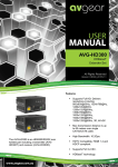
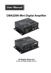
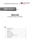
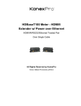
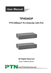
AVG-HD402PR
Features
The AVG-HD402PR uses HDBaseT technology
to deliver HDMI signal with a maximum
transmission distance up to 60 meters with
CAT5e/CAT6 cable.
Supports Full HD: Delivers resolutions
including 800x600@60Hz,
1024x768@Hz,1280x720@60Hz,
1280x1024@60Hz, 1366x768@60Hz,
1600x1200@60Hz,1920x1080@60Hz,
1920x1200@60Hz, 3D, 4K×2K
Max transmission distance is up to 60
meters over single CAT5e/CAT6 cable.
High Bandwidth: 10.2Gps.
HDTV Compatible, HDMI 1.4 and
HDCP compliant.
Supports PoC & CEC.
Connect with a display to transmit
EDID and HPD signals constantly
by using a CAT5e cable.
Uses HDBaseT technology.
Bi-directional RS232/IR control.
LED indicators show working status.
Wall/table-mountable aluminium
enclosure, PT case design.
AVG-HD402PR
PLEASE READ THIS PRODUCT MANUAL CAREFULLY
BEFORE USING THIS PRODUCT.
This manual is only for operation instruction only, and
not to be used in a maintenance capacity. The
functions described in this version are current as at
March 2015. Any changes of functions and
operational parameters will be updated in future
manual versions. Please refer to your dealer for the
latest product details.
Version 1.0 1/3/15
AVG-HD402PR
SAFETY OPERATION GUIDE
In order to guarantee the reliable operation of the equipment and safety of the
user, please abide by the following procedures in installation, use and
maintenance:
1. The system must be earthed properly. Please do not use two blade plugs
and ensure the AC power supply ranges from 100v to 240v and from 50Hz
to 60Hz.
2. Do not install the switcher in an environment where it will be exposed to
extreme hot or cold temperatures.
3. This unit will generate heat during operation, please ensure that you allow
adequate ventilation to ensure reliable operation.
4. Please disconnect the unit from mains power if it will be left unused for a
long time.
5. Please DO NOT try to open the casing of the equipment, DO NOT attempt to
repair the unit. Opening the unit will void the warranty. There are high
voltage components in the unit and attempting to repair the unit could result
in serious injury.
6. Do not allow the unit to come into contact with any liquid as that could result
in personal injury and product failure.
AVG-HD402PR
TABLE OF CONTENTS
Introduction .............................................................................................................. 1
Introduction to the AVG-HD402PR ............................................................... 1.1
Features ....................................................................................................... 1.2
What’s in the Box ........ ……………………………………………………………………2
Product Appearance of the AVG-HD402PR ........................................................... 3
Appearance of AVG-HD402PR ...................................................................... 3.1
Appearance of AVG-HD402T ......................................................................... 3.2
System Connection .................................................................................................. 4
System Applications ..................................................................................... 4.1
Usage Precautions ....................................................................................... 4.2
Connection Diagram ..................................................................................... 4.3
Connection Procedure .................................................................................. 4.4
Twisted Pair Connection ................................................................................ 4.5
Associated Products ...................................................................................... 4.6
Specifications ........................................................................................................... 5
Panel Drawing .......................................................................................................... 6
Troubleshooting & Maintenance ............................................................................. 7
AVG-HD402PR
1. Introduction
1.1. Introduction to the AVG-HD402PR
The AVG-HD402PR is an HDMI/IR/RS232 twisted pair including a transmitter (AVGHD402T) and receiver (AVG-HD402PR). The AVG-HD402PR uses HDBaseT
technology to deliver HDMI signal, max transmission distance up to 60 meters with
CAT5e/CAT6 cable. CEC, bi-directional RS232&IR control, and PoC are supported
by the AVG-HD402PR .
1.2. Features
Supports Full HD: Delivers resolutions including 800x600@60Hz,
1024x768@Hz,1280x720@60Hz, 1280x1024@60Hz, 1366x768@60Hz,
1600x1200@60Hz,1920x1080@60Hz, 1920x1200@60Hz, 3D, 4K×2K
Max transmission distance is up to 60 meters over a single CAT5e/CAT6 cable.
High Bandwidth: 10.2Gps.
HDTV Compatible, uses HDMI 1.4 and is HDCP compliant.
Supports PoC & CEC.
Connect with a display to transmit EDID and HPD signals constantly by
using a CAT5e cable.
Uses HDBaseT technology.
Bi-directional RS232/IR control.
LED indicators show working status.
Wall/table-mountable aluminium enclosure, PT case design.
AVG-HD402PR
2. Package List
1 x AVG-HD402PR
1 x AVG-HD402T
4 x Mounting brackets
8 x Plastic cushions
2 x RS232 cables
8 x Screws
2 x Power adapters (DC 24V)
1 x User manual
Note: Please confirm if the product and the accessories are all included, if not,
please contact your dealer.
AVG-HD402PR
3. Product Appearance of the AVG-HD402PR
3.1. Appearance of AVG-HD402PR
No.
①
②
③
④
⑤
⑥
⑦
⑧
⑨
⑩
Name
Description
Working status indicator, blinks green when the device is
ON
operational, turns off when the device stops working.
Twisted Pair link status indicator, illuminates green when the
LINK
connection is successful.
HDCP compliance indicator, illuminates green when the
connected device supports HDCP and is working normally;
IN
blinks green when the connected device does not support
HDCP.
POWER LED Illuminates red when power is on.
Connects to the HDBT OUT port of a AVG-HD402T with a
HDBT IN
CATx cable.
HDMI OUT
Connects to HDMI display device.
Connect with IR receiver, the IR signal received from this port
IR IN
can only send out via a AVG-HD402T.
Connect with IR transmitter, the sent IR signal are received by
IR OUT
AVG-HD402T.
Serial port, 3-pin captive screw connector, connects with the
RS232
control terminal, supports bi-directional RS232 control.
Connect with power supply (Not necessary if AVG-HD402T
DC 24V
connects with power).
Note: Pictures shown in this manual are for reference only.
AVG-HD402PR
3.2. Appearance of AVG-HD402T
No.
Name
①
ON
②
LINK
③
IN
④
POWER
LED
⑤
HDBT OUT
⑥
HDMI IN
⑦
IR IN
⑧
IR OUT
⑨
RS232
⑩
DC 24V
Description
Working status indicator, blinks green when the device is
operational, turns off when the device is not working.
Twisted Pair link status indicator, illuminates green when the
connection is successful.
HDCP compliance indicator, illuminates green when the
connected device supports HDCP and is operational; blinks
green when the connected device does not support HDCP.
Illuminates red when power is on.
Connect to the HDBT IN port of a AVG-HD402PR with a CATx
cable.
Connects to a HDMI display device.
Connects with IR receiver, the IR signal received from this port
can only send out via a AVG-HD402PR.
Connect with IR transmitter, the sent IR signals are received by
AVG-HD402PR connect with IR transmitter, the sent IR signal
is received by the TPHD402PT.
Serial port, 3-pin captive screw connector, connects with the
control terminal, supports bi-directional RS232 control.
Connect with power supply (Not necessary if AVG-HD402PR
connects with power).
Note: Pictures shown in this manual are for reference only.
AVG-HD402PR
4. System Connection
4.1. System Applications
Reliable performance for control and transmission makes the AVG-HD402PR ideal
in the IT computer space, signal monitoring, big screen displays, conference
systems, television broadcast, education, banking and security institutions etc.
4.2. Usage Precautions
1. System should be installed in a clean environment with temperature and humidity
maintained to within equipment specification.
2. All of the power switches, plugs, sockets and power cords should be insulated
and safe.
3. All devices should be connected before power is turned on.
4.3. Connection Diagram
AVG-HD402PR
4.4. Connection Procedure
Step 1.
Connect HDMI source (such as Blue-ray DVD) to HDMI IN port of AVGHD402T with HDMI cable.
Step 2.
Connect HDBT OUT port of AVG-HD402T to HDBT IN port of AVGHD402PR through a CAT5e/CAT6 cable.
Step 3.
Connect a HDMI display (such as HDTV) to HDMI OUT port of AVGHD402PR with HDMI cable.
Step 4.
Both AVG-HD402T and AVG-HD402PR have IR IN and OUT. When one
end is used as an IR receiver, the other end will be used as an IR
transmitter.
For example: When “IR IN” of AVG-HD402T connects with an IR receiver,
the IR transmitter must be connected to “IR OUT” of AVG-HD402PR.
Step 5.
Connect the RS232 port of the devices to be controlled and the receiver or
the transmitter.
Step 6.
Connect with DC 24V power adaptor(s) (One is sufficient as the other end
can be energized with the PoC function).
AVG-HD402PR
4.5. Twisted Pair Connection
The twisted pair used in this extender MUST be a straight-through cable. The
connectors can be T568A or T568B, but both sides must be the same.
TIA/EIA T568A
68B
PIN
Cable Color
PIN
Cable Color
1
2
3
green white
green
orange white
1
2
3
4
5
blue
blue white
4
5
orange white
orange
Green white
blue
blue white
6
orange
6
green
7
8
brown white
brown
7
8
brown white
brown
4--5
1st
1st
4--5
Ground
Ground
1--2
2nd
2nd
3--6
Ground
Ground
3--6
3rd
3rd
1--2
Group
Group
7--8
4th
4th
7--8
Group
Group
Note: For a more reliable
transmission, cable connectors MUST be metallic, the shielded layer of cable MUST
be connected to the connector’s metal shell.
AVG-HD402PR
4.6. Associated Products
AVG-HD402PR usually works together with other devices to extend the transmission
distance of HDMI/IR/RS232 signal. Here are the most commonly associated
products.
Description:
1) SC51T (mini scaler switcher)
Bi-directional IR & RS232 control.
Compliant with HDCP.
Supports CEC, with commands to enable/disable this function.
Supports video source auto-switching function.
Output resolutions selectable to assure preferred output, and
supports various output resolutions, such as 1920x1200,
1920x1080, 1600x1200, 1360x768, 1280x800, 1280x720, 1024x768.
VGA video supports C-video, YPbPr and VGA.
MIC port supports balance/unbalance signal, suppress the external noise
effectively.
3-level MIC input, supports condenser microphone, dynamic
microphone and wireless microphone.
Powerful OSD function.
2) MA1 (mini digital amplifier)
2x20Watt@4Ω as the default amplifier output.
AVG-HD402PR
Bridge connection function. User can switch the MA1 to be
1x40Watt@8Ω by bridge connection.
48V phantom power to support condenser microphone.
MIC port can support balance/unbalance signal, suppress the
external noise effectively.
AVG-HD402PR
5. Specifications
Model
AVG-HD402T
AVG-HD402PR
Spec
Input
Input Signal
Input Connector
Video Signal
Audio
1 HDMI,1 IR & 1 RS232
HDMI female, 3.5mm
mini jack, 3-pin captive
screw connector
HDMI1.4
Digital audio,
transmit through
HDMI audio
1 IR, 1 RJ-45 & 1 RS232
3.5mm mini jack, RJ45, 3-pin captive
screw connector
HDMI1.4
Digital audio,
transmit through
HDMI audio
1 RJ-45, 1 IR, 1 RS232
RJ-45,
3.5mm
mini
jack,
3-pin
captive
screw connector
HDMI1.4
HD Base T
General
1 HDMI, 1 IR, 1RS232
HDMI female, 3.5mm
mini jack, 3-pin captive
screw connector
HDMI1.4
Output
Output
Output Connector
Video signal
Transmission Mode
Resolution
Transmission Distance
SNR
Bandwidth
THD
HDMI Standard
Impedance
Temperature
Humidity
Power Supply
800x600@60Hz, 1024x768@Hz, 1280x720@60Hz,
1280x1024@60Hz, 1366x768@60Hz,
1600x1200@60Hz, 1920x1080@60Hz,
1920x1200@60Hz, 3D, 4K×2K
Max distance 60M
>70dB@ 100MHz-100M
10.2Gbps
<0.005%@1KHz
Support HDMI1.4, 3D and HDCP
75Ω
-10 ~ +40℃
10% ~ 90%
Input: 100VAC~240VAC, 50/60Hz Output: DC
24V, 1.25A
Power Consumption
9.6W
Dimension (W*H*D)
110 x 77x 30 mm
110 x 77x 30 mm
Net Weight
0.5Kg
0.5Kg
NOTE: All nominal levels are at ±10%
AVG-HD402PR
6. Panel Drawing
AVG-HD402PR
7. Troubleshooting & Maintenance
Problems
Output images in
display contains
ghosting
Causes
Incorrect setting on
the display
Poor cable quality
No signal at the input
/ output end
No output image when
switching
Failed or loose connection
The extender is faulty
Cannot control the
device by control device
(e.g. a PC) through the
RS232 port
Static becomes stronger
when connecting the
video connectors
Cannot control the device
by RS232 / IR remote /
front panel buttons
Solutions
Check the display’s
setting
Try another high
q u a l i t y connection cable
Check with oscilloscope
or multimeter if there is
any signal at the input /
output end.
Re-seat the connection.
Send it to authorized
dealer for repairing.
Wrong RS232
communication
parameters
Make sure the RS232
communication
parameters are correct.
The device has a
previous fault
Send it to authorized
dealer for repairing.
Poor grounding
Check the grounding
and make sure it is
connected well.
The device has a
previous fault.
Send it to authorized
dealer for repairing.