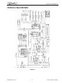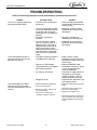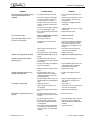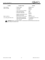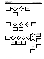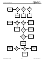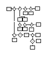
1
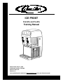
®
ICE FROST
Post-Mix and Pre-Mix
Training Manual
Release Date: May 18, 2005
Publication Number: TP01080
Revision Date: N/A
Revision: A
Visit the IMI Cornelius web site at www.cornelius.com for all your Literature needs.
ICE FROST POST-MIX AND PRE-MIX
TRAINING MANUAL
The products, technical information, and instructions contained in this manual are subject
to change without notice. These instructions are not intended to cover all details or variations of the equipment, nor to provide for every possible contingency in the installation,
operation or maintenance of this equipment. This manual assumes that the person(s)
working on the equipment have been trained and are skilled in working with electrical,
plumbing, pneumatic, and mechanical equipment. It is assumed that appropriate safety
precautions are taken and that all local safety and construction requirements are being
met, in addition to the information contained in this manual.
To inquire about current revisions of this and other documentation or for assistance with
any Cornelius product contact:
www.cornelius.com
1-800-238-3600
Trademarks and copyrights:
Aurora, Cornelius, FlavorFusion, Hydro Boost, Optifill, Pinnacle, and Vanguard are registered trademarks of IMI Cornelius Inc.
This document contains proprietary information and it may not be
reproduced in any way without permission from Cornelius.
Printed in U.S.A.
Copyright © 2005, All Rights Reserved, IMI Cornelius Inc.
TABLE OF CONTENTS
Important Warnings and Advice . . . . . . . . . . . . . . . . . . . . . . . . . . . . . . . . . . . . . . . . . 1
Technical Data . . . . . . . . . . . . . . . . . . . . . . . . . . . . . . . . . . . . . . . . . . . . . . . . . . . . . . . . 1
Plate data . . . . . . . . . . . . . . . . . . . . . . . . . . . . . . . . . . . . . . . . . . . . . . . . . . . . . . . . . 1
Transportation Indications . . . . . . . . . . . . . . . . . . . . . . . . . . . . . . . . . . . . . . . . . . . . . . 1
Specifications . . . . . . . . . . . . . . . . . . . . . . . . . . . . . . . . . . . . . . . . . . . . . . . . . . . . . . . . 2
Installation . . . . . . . . . . . . . . . . . . . . . . . . . . . . . . . . . . . . . . . . . . . . . . . . . . . . . . . . . . . 3
Site Assessment Section . . . . . . . . . . . . . . . . . . . . . . . . . . . . . . . . . . . . . . . . . . . . . . . 4
Water System . . . . . . . . . . . . . . . . . . . . . . . . . . . . . . . . . . . . . . . . . . . . . . . . . . . . . . 4
Syrup System . . . . . . . . . . . . . . . . . . . . . . . . . . . . . . . . . . . . . . . . . . . . . . . . . . . . . . 4
Backup CO2 for Bulk System . . . . . . . . . . . . . . . . . . . . . . . . . . . . . . . . . . . . . . . . . . 4
Electrical System . . . . . . . . . . . . . . . . . . . . . . . . . . . . . . . . . . . . . . . . . . . . . . . . . . . . 4
Counter . . . . . . . . . . . . . . . . . . . . . . . . . . . . . . . . . . . . . . . . . . . . . . . . . . . . . . . . . . . 4
Test Section . . . . . . . . . . . . . . . . . . . . . . . . . . . . . . . . . . . . . . . . . . . . . . . . . . . . . . . 5
Electrical Test . . . . . . . . . . . . . . . . . . . . . . . . . . . . . . . . . . . . . . . . . . . . . . . . . . . . . . 6
Receptacle Test . . . . . . . . . . . . . . . . . . . . . . . . . . . . . . . . . . . . . . . . . . . . . . . . . 6
Volt/Ohm Meter . . . . . . . . . . . . . . . . . . . . . . . . . . . . . . . . . . . . . . . . . . . . . . . . . . 6
Connection Diagrams . . . . . . . . . . . . . . . . . . . . . . . . . . . . . . . . . . . . . . . . . . . . . . . . 7
Ice Frost Generic (Pre-mix) . . . . . . . . . . . . . . . . . . . . . . . . . . . . . . . . . . . . . . . . . 7
Ice Frost Generic (Post-mix) . . . . . . . . . . . . . . . . . . . . . . . . . . . . . . . . . . . . . . . . 8
Pump Installation . . . . . . . . . . . . . . . . . . . . . . . . . . . . . . . . . . . . . . . . . . . . . . . . . . . . 9
Start-up Procedure . . . . . . . . . . . . . . . . . . . . . . . . . . . . . . . . . . . . . . . . . . . . . . . 9
Bowl Loading Operations . . . . . . . . . . . . . . . . . . . . . . . . . . . . . . . . . . . . . . . . . . . . 10
Ice Frost Generic (Pre-mix) . . . . . . . . . . . . . . . . . . . . . . . . . . . . . . . . . . . . . . . . . . . 10
Ice Frost Generic (Post-mix) . . . . . . . . . . . . . . . . . . . . . . . . . . . . . . . . . . . . . . . . . . 10
Brix and Ratio Procedure . . . . . . . . . . . . . . . . . . . . . . . . . . . . . . . . . . . . . . . . . 11
Programming Electronic Touch Pad . . . . . . . . . . . . . . . . . . . . . . . . . . . . . . . . . . . . 12
To Enter Time Programming on Initial Installation or in the Event of Service . . 12
Setting COLD Timer (Night Setting) . . . . . . . . . . . . . . . . . . . . . . . . . . . . . . . . . 13
Operate in Automatic Mode (with COLD Timer Activated) . . . . . . . . . . . . . . . . 13
Operate in Manual Mode (without COLD Timer Activated) . . . . . . . . . . . . . . . . 13
Setting the 12 or 24 Hour Display and oF or oC Temperature Display . . . . . . 13
Viewing the Bowl Temperature . . . . . . . . . . . . . . . . . . . . . . . . . . . . . . . . . . . . . 14
Dispensing Product . . . . . . . . . . . . . . . . . . . . . . . . . . . . . . . . . . . . . . . . . . . . . . . . . 14
Consistency Adjustment . . . . . . . . . . . . . . . . . . . . . . . . . . . . . . . . . . . . . . . . . . . . . 14
Alarms . . . . . . . . . . . . . . . . . . . . . . . . . . . . . . . . . . . . . . . . . . . . . . . . . . . . . . . . . . . 15
Safety Probe Alarms (only for Ice Frost Generic Pre-mix) . . . . . . . . . . . . . . . . 15
1st Filling Time-out . . . . . . . . . . . . . . . . . . . . . . . . . . . . . . . . . . . . . . . . . . . . . . 15
Filling Time-out . . . . . . . . . . . . . . . . . . . . . . . . . . . . . . . . . . . . . . . . . . . . . . . . . 15
“FILTER CLEANING” Alarm . . . . . . . . . . . . . . . . . . . . . . . . . . . . . . . . . . . . . . . 16
“SYSTEM OVER TEMPERATURE” Alarm . . . . . . . . . . . . . . . . . . . . . . . . . . . . 16
Bi-Annually Cleaning and Sanitation . . . . . . . . . . . . . . . . . . . . . . . . . . . . . . . . . . . . 17
Special Maintenance . . . . . . . . . . . . . . . . . . . . . . . . . . . . . . . . . . . . . . . . . . . . . . . . . . 21
Restricted Air Flow Alarm . . . . . . . . . . . . . . . . . . . . . . . . . . . . . . . . . . . . . . . . . . . . 22
Electronic Monitoring . . . . . . . . . . . . . . . . . . . . . . . . . . . . . . . . . . . . . . . . . . . . . . . . .
Electronic Bowl Monitoring and Safety System . . . . . . . . . . . . . . . . . . . . . . . . . . . .
Pressure and Level Control Card General Features . . . . . . . . . . . . . . . . . . . . . . . .
OFF Condition . . . . . . . . . . . . . . . . . . . . . . . . . . . . . . . . . . . . . . . . . . . . . . . . . . . . .
1st Filling Condition . . . . . . . . . . . . . . . . . . . . . . . . . . . . . . . . . . . . . . . . . . . . . .
Managing the Bowl Levels . . . . . . . . . . . . . . . . . . . . . . . . . . . . . . . . . . . . . . . .
Safety Probes (only for Ice Frost Generic Pre-mix) . . . . . . . . . . . . . . . . . . . . .
23
23
24
25
25
26
26
Wiring Diagram . . . . . . . . . . . . . . . . . . . . . . . . . . . . . . . . . . . . . . . . . . . . . . . . . . . . . .
VFCB (Pre-Mix) 115V/60Hz . . . . . . . . . . . . . . . . . . . . . . . . . . . . . . . . . . . . . . . . . .
VFCB (Post-Mix) 115V/60Hz . . . . . . . . . . . . . . . . . . . . . . . . . . . . . . . . . . . . . . . . .
VFCB (Pre-Mix) 230V/50Hz . . . . . . . . . . . . . . . . . . . . . . . . . . . . . . . . . . . . . . . . . .
VFCB (Post-Mix) 230V/50Hz . . . . . . . . . . . . . . . . . . . . . . . . . . . . . . . . . . . . . . . . .
28
28
29
30
31
Troubleshooting . . . . . . . . . . . . . . . . . . . . . . . . . . . . . . . . . . . . . . . . . . . . . . . . . . . . . 32
Ice Frost Training Manual
IMPORTANT WARNINGS AND ADVICE
This instruction manual represents an integral part of the equipment and must be kept readily available
for use.
Read the warnings contained herein carefully before installing and using this equipment.
In addition to offering information concerning routine maintenance for the Ice Frost machine and
technical back-up for troubleshooting, this manual aims to help the user make the most of the machine’s
potential, adapting it to suit the specific needs of the various countries it will be used in.
Modifications or attempts to modify the equipment will not only result in the forfeiture of the guarantee,
but are also extremely dangerous.
The maintenance operations must be carried out by qualified professionals. Never attempt to repair the
machine yourselves as the intervention of non-qualified persons, as well as being hazardous, could also
lead to serious damage to the machine.
TECHNICAL DATA
PLATE DATA
The voltage and the frequency are indicated on the serial number plate, located on the refrigeration deck
and the right hand side near the controls.
TRANSPORTATION INDICATIONS
To prevent the oil contained in the compressor from flowing out into the cooling circuit, the equipment
must be transported, stored, and handled in a vertical position, as per the indications given on the
packing.
The wooden pallet, equipped with housing for the lifting forks, allows the packed equipment to be moved
using normal handling and hoisting means.
© 2005, IMI Cornelius Inc.
-1-
Publication Number: TP01080
Ice Frost Training Manual
SPECIFICATIONS
Bowl Capacity: 2.1 Gallon (8 liter) per bowl
Electrical Ratings:
Voltage
Amperage
115V/60Hz
220V/60Hz
230V/50Hz
Fuse
13.8
8.0
6.7
20
10
10
Installation Requirements: Allow 8” (200mm) minimum clearance around back and 4” (100 mm)
clearance around both sides.
Post-Mix:
Carbonated Water Supply = 1/4” (6.5 mm) barb connection
BIB Pump and Rack - 2 Pump - 1/4” (6.5mm) barb connection
Accessories:
Carbonator Pump and Tank
Pre-Chill
Cart
Shipping Dimensions:
Width
Length
Height
Weight
Dispenser
18.0” (480 mm)
26.0” (660 mm)
39.8” (1,010 mm)
187 lb (85 kg)
Cart
25.6” (650 mm)
31.5” (800 mm)
45.3” (1,150 mm)
123 lb (56 kg)
Operating Dimensions (FIGURE 1):
A
63.0” (160 mm)
B
14.4” (365 mm)
C
16.5” (420 mm)
D
24.4” (620 mm)
E
36.0” (915 mm)
F
71.5” (1,815 mm)
G
20.7” (525 mm)
H
29.5” (750 mm)
E
B
F
C
D
A
H
G
FIGURE 1
Publication Number: TP01080
-2-
© 2005, IMI Cornelius Inc.
Ice Frost Training Manual
INSTALLATION
1.
2.
Remove the equipment from the packing, then slide it off upwards
(see FIGURE 2).
Checking the machine identification after removing the packing,
you must check that the equipment you have received is exactly as
you ordered, making sure the specifications indicated on the
invoice or the delivery note are identical to those on the data plate.
FIGURE 2
3.
Equipment accessories
The following accessories are included inside the bowls:
• This Installation and Operator’s Manuals;
• 1 tube of Vaseline to be used for the maintenance machine the requires;
• A drip tray.
The back-lit cover is packed separately from the machine.
4.
Positioning - make sure the machine’s bodywork is well ventilated, at least 6”, and do not install near
heat sources.
We recommend you keep the room temperature at between 59 and 77°F.
IMPORTANT: All the pieces of packing must be kept out of reach of children as they represent
potential hazards.
5.
Remove gear motor shipping pins and tags from the rear of the unit prior to installation.
© 2005, IMI Cornelius Inc.
-3-
Publication Number: TP01080
Ice Frost Training Manual
SITE ASSESSMENT SECTION
WATER SYSTEM
•
Filters: Coarse? ____ Taste/Odor? ____ Scale Inhibitor? ____
•
Is water main ½ inch I.D. minimum? ____
•
Pressure Static? ____
•
Pressure Flowing?____
•
Length of run? ___
•
Shut off valve? ____
•
Back flow prevention? ____
•
Is water softened? ____
•
Is water line connected to a water heater? ____
•
Perform water test to insure that the minimum flow and pressure requirements are met or exceeded.
SYRUP SYSTEM
•
Is there adequate space available for the number of boxes required to supply all valves?
•
Is there room for extra boxes and change over valves?
•
Is there space to mount the syrup pumps level with the boxes or above them?
•
Distance between the boxes and pumps should not be greater then 10 feet, vertical rise should not be
more then five feet.
•
Minimum tubing size between the pumps and unit is 3/8 I.D.
•
Syrup viscosities are affected by temperature 50 degree ambient or above is recommended.
•
Some units require higher flowing pressures then others (e.g. The Pinnacle FCB requires 45 p.s.i.g.
flowing pressure at the unit.)
If you suspect syrup supply problems, tee a pressure gauge into the supply line just before it inters the
unit. Start the Blendonator and read the pressure gauge while the product pump is running, the gauge
should not drop below 45p.s.i.g. if the flowing pressure is adequate.
BACKUP CO2 FOR BULK SYSTEM
•
Bulk tanks require Secondary Regulators; maximum inlet pressure should not exceed 200 p.s.i.g.
•
High pressure tanks require Primary Regulators; inlet pressure must be 500 p.s.i.g. minimum.
•
Supply lines longer then 100 feet require 3/8 ID tubing.
3/8 tubing should be used on all new installations.
ELECTRICAL SYSTEM
•
Is there a dedicated electrical circuit for each of the dispensers or ice makers?
•
Is there an outlet within 6 feet of the dispenser or ice maker?
•
Is the outlet polarity correct with a good ground connection?
COUNTER
•
Are the counters large enough for the unit foot print, considered power cord, supply lines and Air flow
if applicable?
•
Will the counters support the weight of the dispenser and ice maker?
•
If the unit is an ice cooled drop in, is there room between the counter top and the floor for the ice bin?
Publication Number: TP01080
-4-
© 2005, IMI Cornelius Inc.
Ice Frost Training Manual
TEST SECTION
Water pressure& volume test:
Estimate the water usage of all equipment connected to the water delivery system (e.g.Intellicarb = 125
G.P.H. a two Fl. Pinnacle = 100 G.P.H. Total = 225 G.P.H.) Select the 13/64 orifice to insure that you can
supply more then the 225 G.PH. Required to operate both units.
Connect the IMI Cornelius water test device (FIGURE 3) to the supply line that will be connected to the
unit.
Select the correct orifice for the static or flowing pressure that you need to verify.
Turn on the water supply, open tester shut off valve and allow the water to flow into a drain or bucket for at
least 20 seconds, read the pressure gauge while the water is still flowing, or just take the gauge reading
if static pressure is being checked.
Pressure Gauge
Inlet Line
Shutoff Valve
No Hole = Static Pressure
Large (13/64”) = 300 GPH
Small (1/8”) = 100 GPH
Medium (3/16”) = 200 GPH
FIGURE 3
If the gauge is reading 25 PSI (FIGURE 6) or higher with the 13/64 orifice installed you are flowing at 300
GPH or more.
FIGURE 4. Static Pressure = 60 psig
© 2005, IMI Cornelius Inc.
FIGURE 5. Low Water Volume = less
than 25 psig
-5-
FIGURE 6. Proper Water Pressure
Volume = greater than 25 psig
Publication Number: TP01080
Ice Frost Training Manual
ELECTRICAL TEST
Receptacle Test (FIGURE 7)
•
Open ground - Ground contact not connected.
•
Open neutral - Neutral contact not connected.
•
Open hot - Hot contact not connected.
•
Hot and ground reverse - Hot and Ground contacts interchanged.
•
Hot and Neutral reversed - Hot and neutral contacts interchanged.
FIGURE 7
Volt/Ohm Meter (FIGURE 8)
Check the following:
•
Voltage at receptacle.
•
Correct voltage range.
Used to troubleshoot the unit and components.
FIGURE 8
IMPORTANT: If the power supply cord is damaged, it must be replaced by qualified persons only
to prevent any possible risks.
Publication Number: TP01080
-6-
© 2005, IMI Cornelius Inc.
Ice Frost Training Manual
CONNECTION DIAGRAMS
Ice Frost Generic (Pre-mix)
The diagram shows the sequence for the connection between the ICE FROST GENERIC PRE to an
existing pre-mix system.
FIGURE 9
Description:
1. Pre-mix product 1 inlet.
2. Pre-mix product 2 inlet.
4. Inlet for CO2 (coming from the pressure reducing valve, 12 psi).
5.
CO2 gas cylinder.
6.
7.
Operating pressure gauge.
8.
9.
10.
11.
Gas cylinder pressure gauge.
Pre-mix product 1 container.
Pre-mix product 2 container.
Cooling unit (Optional).
CO2 pressure regulator.
Connection:
Connect the points 1, 2, and 4 on the machine to the existing pre-mix system using quick couplings.
© 2005, IMI Cornelius Inc.
-7-
Publication Number: TP01080
Ice Frost Training Manual
Ice Frost Generic (Post-mix)
The diagram shows the sequence for the connection between the ICE FROST GENERIC POST to an
existing post-mix system.
FIGURE 10
Description:
1. Syrup 1 inlet.
2. Syrup 2 inlet.
3. Soda water inlet.
4. Inlet for CO2 45 to 60 psi.
5.
CO2 gas cylinder.
6.
7.
8.
9.
10.
11.
12.
13.
14.
15.
16.
17.
18.
Operating pressure regulator for carbonation unit.
Carbonation unit operating pressure gauge.
Unit and BIB operating pressure gauges.
Pressure regulator.
Gas cylinder operating pressure gauge.
Water Pressure regulator.
Filter.
Carbonation unit and optional precooling unit.
Syrup 1 pump.
Syrup 2 pump.
Bag-in-box exchanger.
Bag-in-box exchanger.
Bag-in-box.
Connection:
Connect the points 1, 2, 3, and 4 on the machine to the existing post-mix system using quick couplings or
.265 splice connectors.
Publication Number: TP01080
-8-
© 2005, IMI Cornelius Inc.
Ice Frost Training Manual
PUMP INSTALLATION
•
As indicated on the pump, the outlet port is to be mounted up.
•
Pumps are to be mounted at the same level or higher than the B-I-B. The best choice is to have the
pump above the B-I-B.
•
INLET tubing from the B-I-B to the pump use; 3/8” I.D. [10mm] minimum, heavy wall (1/8”
[3mm]) clear, NSF listed vacuum tubing. Inlet tubing should not have excessive length. Tubing
that is allowed to drape down can trap air in the B-I-B creating a potential for pump “sold-out”
problems. The maximum vertical distance from the bottom of the B-I-B to the pump must not
exceed 5 feet [1.5 M]. Maximum inlet tubing length is 10 ft. [3 M].
•
If plumbing multiple B-I-Bs to a pump, B-I-Bs should be “Teed” side-by-side horizontally,
rather than one on top of the other (vertically).
•
OUTLET tubing from the pump to the dispenser should be high pressure rated and NSF
listed. Consult “Plumbing Capability” (see page 2) for appropriate tubing I.D.
•
Always cut CO2 and outlet tubing at least 2 ft. [.6 M] longer to provide a “service loop” so the
B-I-B rack can be moved for cleaning or service.
•
Use new (clean), 1/4” I.D. [6 mm], flexible, high pressure, braided tubing from the CO2/ air
regulator to the pump.
NEVER connect a transfer tank “system” in series with a B-I-B system. Syrup contaminants in
old components may work their way through the air supply causing premature failure of the gas
pump. Gas used to operate pumps MUST be clean and contain no contaminants (syrup, oil, rust,
water, etc.). Air compressors may be used with proper particle filters and moisture separators. Air
storage tanks should be drained regularly. Pumps subjected to contaminated air are not covered by
warranty.
High concentrations of CO2 can be fatal as it will displace the oxygen from non-ventilated areas.
Pumps operated by CO2 must be in ventilated areas.
If placed in a confined area (basement, closet, cooler box, etc.), exhaust fans capable of changing
the room air on a continuous basis should be used.
•
All tubing connections must be secured with stainless steel, stepless® Oetiker® clamps.
•
Cable-tie all tubing securely to prevent kinks or sags that inhibit performance or cause damage to the
pump fittings.
Start-up Procedure
1.
2.
3.
4.
Confirm that all tubing connections are properly clamped, fittings are tight, and tubing is not kinked.
Install bag connector to the B-I-B.
Adjust gas regulator to about 20 psi. [1.4 bar] allowing the pump to stroke slowly.
Operate the valve until all air trapped within the tubing has been purged.
Once the air has been purged, adjust the CO2 regulator to the pressure necessary to maintain the desired brix. The most efficient gas usage occurs at 40 psi. [2.8 bar]. MAXIMUM
static gas pressure to the pump is 85 psi. [5.8 bar], minimum 20 psi. [1.4 bar].
Flow rates that result in a stroke-rate of more than two strokes per second will decrease pump
life. (Consult factory) Pump failure due to “overrunning” is not covered by the limited warranty.
To prevent air from entering the system always leave the bag connector attached to the empty
B-I-B until a new B-I-B can be installed. Air entered into the system, via air in the bags or
vacuum leaks, may cause brix fluctuation, foaming, spitting, non-operation of the vacuum soldout or pump “run-on” with the valve closed. Symptoms of this kind can lead to a misdiagnosis of the
pump.
© 2005, IMI Cornelius Inc.
-9-
Publication Number: TP01080
Ice Frost Training Manual
BOWL LOADING OPERATIONS
ICE FROST GENERIC (PRE-MIX)
WARRNING: If the unit runs out of product and is turned off and turned back on without a
new (full) product tank installed the sensor will look for product for 4 minutes. During this 4
minute period CO2 will be purged from the bowl.
•
Switch the machine’s main switch to the ON position (1).
•
Put the switch (A) into the ON position (1) see FIGURE 11,
switch A. Controls the flow of the product in the bowls.
•
The machine’s bowls will now fill up until the maximum level
is reached.
•
Continue with start up operations.
A
B
FIGURE 11
ICE FROST GENERIC (POST-MIX)
•
Switch the machine’s main switch to the ON position (1).
•
Make sure the switch FIGURE 11, Item A is in the OFF
position (0) - (the switch controls the flow of the products in
the bowls).
•
Turn mixing motors OFF immediately. Do not run units with
bowls empty.
•
Using an 1/8 inch (8 mm) socket wrench, loosen the nut that
holds the post-mix valve.
•
Twist nozzle counter-clockwise, lift the post-mix valve up
slightly and turn it towards the outside, leaving nozzle and
coupling attached to the bowl.
Publication Number: TP01080
- 10 -
A
FIGURE 12
© 2005, IMI Cornelius Inc.
Ice Frost Training Manual
Brix and Ratio Procedure
•
Now pull the post-mix valve out further and tighten the 1/8 inch (8mm) nut (FIGURE 12, A) using the
socket wrench.
•
Remove the post-mix valve’s nozzle and apply the syrup
separator (B), then the ratio cup (C) and push the micro
switch on the valve (A) until both the soda water and the
syrup run into the measuring cup separately (FIGURE 13).
•
To adjust ratio: turn the water adjustment screw on the
solenoid valve clockwise to increase or counter-clockwise to
decrease the amount of water in the product.
•
When the desired ratio has been found, remove the parts B
and H1, replace the spout on the post-mix solenoid valve,
then position it in its original seating, performing the previous
operations in reverse order.
•
A refractometer may be used to check Brix as an alternative
to ratio measurement.
A
B
C
FIGURE 13
•
Repeat the same operations for the second bowl.
•
Once the adjustments have been carried out for each bowl, place the switch (FIGURE 11, A) in the
ON position (1).
•
Both bowls will begin to fill up when the level sensor is activated.
•
Turn mixing motors ON (located on the control board).
•
Unit has built in delays for compressor and bowl fill switch.
•
During initial filling it is normal for some foaming to take place. Bowl level management will adjust as it
freezes down and foam will dissipate.
© 2005, IMI Cornelius Inc.
- 11 -
Publication Number: TP01080
Ice Frost Training Manual
PROGRAMMING ELECTRONIC TOUCH PAD
To lower/open the control cover, use a coin or other object to turn the keyless lock to the horizontal position, in order to open access the operating panel (controls are located on the right side of the unit).
Auger ON/OFF Button
Main Power Switch
• Turns unit ON.
Fo
o
• Selects 12/24 time clock or /C temperature display when turned ON while simultaneously depressing the auger button.
• Sets current time when turned ON while
simultaneously depressing the “PRESS TO
SELECT FUNCTION” button.
• Turns auger ON and OFF when main
power switch is ON.
• Must be ON to permit COLD time to be
reset.
• Must be ON to activate the “PRESS TO
SELECT FUNCTION” button to select manual
“OFF”, “FREEZE”, or “COLD” functions.
FIGURE 14
PRESS TO SELECT FUNCTION Button
“AUTO TIMER” Button
• Used to manually select “OFF”, “FREEZE”,
or “COLD” functions when auger is turned
ON.
• Turns auto COLD mode ON or OFF (light
on switch indicates when auto COLD mode is
activated).
• Accesses COLD timer reset mode when
depressed for an extended period when
auger is turned ON.
• Used to adjust the hours and minutes settings when readjusting current time or auto
COLD timer.
• Locks in hours, minutes and final time settings after they are reset using the “AUTO
TIMER” button.
Temperature Separator
• Does not function when light on “AUTO
TIMER” button is illuminated.
• This is a place holder to separate the
right and left temperatures.
To Enter Time Programming on Initial Installation or in the Event of Service
1.
2.
Turn the power switch OFF.
Press and hold the left “PRESS TO SELECT FUNCTION” button and turn ON the power switch.
Release the “PRESS TO SELECT FUNCTION” button when the hour digits start blinking.
3. Set the hour by pressing the “AUTO TIMER” clock button until the appropriate hour is shown.
NOTE: When using a 12 hour clock the time is P.M. when the dot at the bottom right corner of the
LED display is lit; A.M. when dot is not lit.
4.
5.
Press the left “PRESS TO SELECT FUNCTION” button to set the minutes, then press the “AUTO
TIMER” clock button until the appropriate minutes are set.
Press the “PRESS TO SELECT FUNCTION” button one more time to save your settings.
Publication Number: TP01080
- 12 -
© 2005, IMI Cornelius Inc.
Ice Frost Training Manual
Setting COLD Timer (Night Setting)
1.
2.
3.
Turn the power switch ON. Make sure the “AUTO TIMER” is OFF (i.e. light on button is not lit).
Press the left hand “Auger ON/OFF” button ON.
Press and hold the “PRESS TO SELECT FUNCTION” button until you hear a long beep and the
LED, “Cold” and the “AUTO TIMER” clock light begins to blink.
4. Press the “AUTO TIMER” clock button to set the unit to COLD mode and then press the “PRESS TO
SELECT FUNCTION” button to save the setting.
5. Press the “AUTO TIMER” clock button to set the minutes to complete time setting that you want it to
turn to COLD mode. Then press the “PRESS TO SELECT FUNCTION” button to save the minute
setting. The “COLD” light will turn off and the “FROZEN” light and “AUTO TIMER” light will begin
blinking.
6. Set the time you want the machine to return to FROZEN mode by following steps 1 - 5 above. Then
press the “PRESS TO SELECT FUNCTION” button to save the time settings. The FROZEN light
should be blinking.
7. Repeat steps 1 - 6 for the opposite bowl using the left buttons.
NOTE: Once the settings have been saved, the unit will keep the settings, even when the power
switch is turned OFF.
NOTE: When the light on the “AUTO TIMER” clock button is “ON”, the COLD timer is activated. To
turn OFF the COLD timer, press the “AUTO TIMER” clock button(s) until the light(s) on the clock
button(s) turns off.
Operate in Automatic Mode (with COLD Timer Activated)
1.
2.
3.
4.
Turn power switch ON and wait for LED display to light up.
Press the left hand “Auger ON/OFF” button ON.
To operate in COLD mode press the “AUTO TIMER” button until it is illuminated.
When setting automatic times, please keep in mind it will take time for the frozen product to become
liquid or vice versa.
Operate in Manual Mode (without COLD Timer Activated)
1. Turn the power switch ON and wait for LED display to light up.
2. Make sure the clock button is OFF (LED light on clock button should not be lit up).
3. First turn auger ON by pressing the “Auger ON/OFF” button until it beeps.
NOTE: The auger must be ON before the unit will allow the COLD or FROZEN mode to be
activated.
4.
Then select COLD or FROZEN mode by pressing the “PRESS TO SELECT FUNCTION” button
until the light under the selection you desire is lit up.
NOTE: In the COLD mode, the LED will read the actual temperature of the product (the
temperature setting is preset to NSF standards and is not adjustable.) In the “FROZEN” or “OFF”
mode the LED will read the current time.
Setting the 12 or 24 Hour Display and
oF
or oC Temperature Display
1.
2.
Turn the power switch OFF.
Press and hold the left “AUGER ON/OFF” button and turn ON the power switch. Release the
“AUGER ON/OFF” button when either “12” or “24” are shown (indicates the current hour view).
3.
Press the “PRESS TO SELECT FUNCTION” button until either oF or oC is shown on the display.
4.
5.
Press the “AUTO TIMER” button until the desired temperature display type is shown (oF or oC).
Store the change by pressing the “PRESS TO SELECT FUNCTION” button until the current time is
displayed. The unit is now ready for use.
© 2005, IMI Cornelius Inc.
- 13 -
Publication Number: TP01080
Ice Frost Training Manual
Viewing the Bowl Temperature
1.
2.
Turn ON the auger on the side that you want to display the bowl temperature (press the “AGER ON/
OFF” button).
Press the “PRESS TO SELECT FUNCTION” button until the “Cold” LED is lit. The display will now
show the current bowl temperature in either oF or oC as applicable.
DISPENSING PRODUCT
1.
To dispense the product, place the cup beneath the
dispensing valve and pull the lever very gently (FIGURE
15).
FIGURE 15
CONSISTENCY ADJUSTMENT
2.
Adjusting the viscosity (consistency):
To vary the viscosity of the product, turn the knob as
shown in FIGURE 16.
Turning the knob counter-clockwise will increase viscosity
(make the product denser).
Turning the knob clockwise will decrease viscosity (make the
product less dense).
ATTENTION: This control only changes the viscosity of the
product dispensed, it does not effect the COLD
temperature.
FIGURE 16
ATTENTION: When the level of the product inside the bowl
is below the minimum level, you must switch the COLD
system to the OFF position, or refill the bowl, following the
instructions given in the previous paragraphs.
An indicator gauge for reference is located on the back of the
unit approximately 6 inches below the adjustment knob.
NOTE: This indicator can not be viewed on all models.
NOTE: Do not turn knob after you reach the upper or lower
limits. Doing so can damage the assembly.
Publication Number: TP01080
- 14 -
© 2005, IMI Cornelius Inc.
Ice Frost Training Manual
ALARMS
Safety Probe Alarms (only for ICE
FROST GENERIC Pre-mix)
You will remember that the monitoring of the safety probes’ conditions (satisfied/ not satisfied) is only
active during the bowl loading phase. It follows, then, that a lack of liquid in the tanks during the nonloading phases will not be signalled.
When one of the two safety probes fail to detect the flow (presence) of liquid during the loading phase,
the system will stop (3-second software filter) the loading phase in progress, while the buzzer on the
machine emits an intermittent warning signal lasting 6 seconds.
The fill solenoid connected to the system where the lack of liquid has been detected by the safety probe
input can only be energized by switching the system OFF then ON again (cycling power resets fill
operation).
If both the safety probes fail to detect a presence of liquid while the bowls are loading, the buzzer on the
card will emit an intermittent sound lasting approximately 20 seconds.
The bowl fill solenoids are command (OFF). The normal operation conditions can be restored by
switching the machine OFF then ON again using the main switch.
The bowl pressure valve solenoid valve is independent of the alarm signal and continues its
CO2 gas pressure reading function only.
1st Filling Time-out
A time limit has been set for the first filling phase which is linked to the level probes detection of the
presence of liquid.
When one of the two level probes fails to detect the presence of liquid for more than four seconds, the
buzzer on the card will emit an intermittent sound for approximately 6 seconds.
The fill solenoid connected to the system where the lack of liquid has been detected by the safety probe
input can only be reset by switching the system OFF then ON again.
When both the level probes fail to detect a presence of liquid for more than four seconds, the buzzer on
the card emits an intermittent sound lasting approximately 20 seconds.
All the solenoids linked to the system are disabled (bowl fill and CO2 gas management valves = OFF).
The normal operating conditions can be resumed by switching the system OFF and then ON again.
Filling Time-out
A time limit has been set for the normal filling phase which is linked to the level probes detection of the
presence of liquid (bowl replenishment during normal draw).
When one of the two level probes fails to detect the presence of liquid for more than one minute, the
buzzer on the card will emit an intermittent sound for approximately 6 seconds.
The fill solenoid connected to the system where the lack of liquid has been detected by the safety probe
input can only be energized by switching the system OFF then ON again.
When both the level probes fail to detect a presence of liquid for more than on minute, the buzzer on the
card emits an intermittent sound lasting approximately 20 seconds.
The bowl fill solenoids are command (OFF). The normal operating conditions can only be resumed by
switching the system OFF and then ON again.
The CO2 gas management valve solenoid valve is independent of the alarm signal and
continues its CO2 gas pressure reading function only (see relevant paragraph).
© 2005, IMI Cornelius Inc.
- 15 -
Publication Number: TP01080
Ice Frost Training Manual
“FILTER CLEANING” Alarm
A filter cleaning alarm will activate when the system is running HOT due to insufficient internal air
circulation. When this occurs a “Filtr” message will appear on the touch pad LED display readout and an
intermittent tone will also sound to alert the operator of this condition.
The “Filtr” message will appear when the alarm activates (a beeping sound every 4-5 seconds). To
correct the condition that caused the alarm and correct problem, see list of conditions below:
Condition
Corrective Action
•
The filter is dirty and needs to be cleaned.
• Clean and replace filter following instructions
(Removing and Cleaning Filter).
•
The unit is positioned too close to a wall or
other object restricting air flow and causing
the machine to run at a higher temperature.
• Reposition unit to maximize ventilation space
(Installation Instructions).
•
The filter is not properly installed.
• Properly install filter (Removing and cleaning filter).
•
• Reposition unit to maximize ventilation space.
The unit has been installed near a heat
source, such as a coffee machine, ice maker
or cold beverage machine which expels hot
air from its vents, causing the machine to run
at a high temperature (installation near a
heat source should be avoided).
“SYSTEM OVER TEMPERATURE” Alarm
A system over temperature alarm will activate as a safety precaution when the unit has overheated to
protect the compressor.
•
The system automatically goes to “OFF” status where the compressor’s operations is stopped, while
augers will keep working to avoid forming ice blocks.
•
When this occurs an “Err” message will appear on the touch pad LED readout accompanied by a
continuous buzzer sound to alert the operator of this condition.
•
When this alarm sounds, turn OFF all switches. Then determine the reason for the alarm. (See “Filter
Cleaning” Alarm Section for Conditions and Corrective Actions).
Publication Number: TP01080
- 16 -
© 2005, IMI Cornelius Inc.
Ice Frost Training Manual
BI-ANNUALLY CLEANING AND SANITATION
ATTENTION: The cleaning operations must be performed with the machine disconnected from the
power supply.
1.
2.
Empty the bowl of any remaining product and switch off the main switch see FIGURE 14 on
page 12.
Remove the cover (B) - FIGURE 30.
3.
Extract the quick couplings (C2) / (F2) - (FIGURE 17, FIGURE 18, and FIGURE 19).
FIGURE 18
FIGURE 17
FIGURE 19
4.
Disconnect the probe fastenings (FIGURE 17, FIGURE 18, and FIGURE 19).
5.
Pull the lockpin/safety pin upwards
(FIGURE 20, A).
A
CAUTION: There is a spring below the
safety pin. Take caution when removing
the pin that the spring does not fall into the
unit or eject the pin.
FIGURE 20
© 2005, IMI Cornelius Inc.
- 17 -
Publication Number: TP01080
Ice Frost Training Manual
6.
Slide the locking bar (FIGURE 22) out so
that the bowls are fully released.
Unlock relief valve on the bowl lid cap and
remove (FIGURE 20).
FIGURE 21
FIGURE 22
7.
Unscrew the knobs (FIGURE 23) so the
bowls can be lowered slightly, open the tap
to remove any remaining liquids and then
pull it forward from its seating.
FIGURE 23
Publication Number: TP01080
- 18 -
© 2005, IMI Cornelius Inc.
Ice Frost Training Manual
8.
Remove the tap from its valve body,
pressing the two clamping wings at the
same time (FIGURE 24) and pushing
upwards.
9.
Remove the tap, holding the body pressed downwards, then slide the lever out of the valve body.
Wash all the parts thoroughly with hot water and mild detergent, rinse them well, and replace them.
FIGURE 24
10. Separate the bowl from its cover, releasing
the fastening by pulling them upwards and
rotating them a quarter turn, as shown in
FIGURE 25.
FIGURE 25
11. Wash the bowl and cover carefully with
water and mild detergent, rinse them well,
and replace them, making sure the sealing
strip (A) is positioned correctly between
the cover and the bowl. To guarantee the
seal, the rounded part of the said sealing
strip (as shown in FIGURE 26) must be
facing the cover.
A
FIGURE 26
© 2005, IMI Cornelius Inc.
- 19 -
Publication Number: TP01080
Ice Frost Training Manual
12. Unscrew the fastening knob (A) clockwise
as the direction indicated by the arrow
(threading to the left) and extract the spiral
scraper (C) and the seals (B) and (D).
Clean the individual parts thoroughly
(FIGURE 27).
C
D
B
A
FIGURE 27
13. Clean the drip tray (A) and the evaporator
(B) (FIGURE 28).
14. Replace the mixing unit as follows:
• Dampen the sealing strip (FIGURE 27,
D) and insert it into its seating.
• Apply a generous amount of food grade
lubricant (supplied with the machine) to
the suction cup seal (FIGURE 27, B) (on
the part that comes into contact with the
evaporator FIGURE 28, B) and insert it
in its spiral seating.
B
A
FIGURE 28
• Replace the spiral scraper (FIGURE 27,
C).
• Fasten all the components in place by
screwing the knob (FIGURE 27, A)
counter-clockwise.
15. Replace the bowl by pushing it into its seating.
16. Fasten the bowl in place by tightening the knobs (FIGURE 23) and the locking bar (FIGURE 21).
17. Replace the tap, remembering to smear both is seating in the bowl and the seals with food grade
lubricant
18. Remove the drip tray (L1) by rotating it
slightly and pulling it outwards (FIGURE
29).
Wash all the parts carefully and
reassemble it by following the prior
operations, remembering to re-insert the
condensation discharge pipe (M1) in its
seating.
FIGURE 29
Publication Number: TP01080
- 20 -
© 2005, IMI Cornelius Inc.
Ice Frost Training Manual
SPECIAL MAINTENANCE
ATTENTION: To guarantee peak cooling
system performance, the routine cleaning of
the condenser filter is essential.
As explained earlier, an audible signal accompanied by
the word FILT appearing on the control panel display,
will warn the operator when the filter is clogged and so
must be cleaned before the machine comes to an
automatic stop.
•
Disconnect the machine from the power supply;
•
Unscrew the nut (C in FIGURE 30).
•
Remove the cover (B in FIGURE 30).
•
Disconnect the plug (D in FIGURE 31).
•
Loosen and rotate the bracket.
•
Lift and remove the back (E in FIGURE 31).
•
Clean the filter behind the net, then clean the
condenser with a brush, if necessary.
WARRNING: You are reminded that all the operations described above must be carried out with
the machine switched off and the power cable disconnected.
•
FIGURE 30
FIGURE 31
Clean the CO2 manifold while you have access to
the back of the unit.
A. Open the John Guest valve, shown in FIGURE
32, and allow the manifold CO2 pressure to blow
any liquid that might be in the manifold out of
the tube.
FIGURE 32
© 2005, IMI Cornelius Inc.
- 21 -
Publication Number: TP01080
Ice Frost Training Manual
RESTRICTED AIR FLOW ALARM
To protect the entire cooling system, the Ice Frost
drinks maker is fitted with an electronic system which
issues an acoustic warning signal in the event of
insufficient ventilation or if the condenser filter is
clogged. In addition to this, the words FILT and then
ERR will appear on the control panel display.
FIGURE 33
If the operator does not intervene when the signal is issued, restoring normal working conditions (i.e.
ensuring better ventilation or cleaning the filter), this electronic control system will stop the machine
automatically.
Publication Number: TP01080
- 22 -
© 2005, IMI Cornelius Inc.
Ice Frost Training Manual
ELECTRONIC MONITORING
ELECTRONIC BOWL MONITORING AND SAFETY SYSTEM
The diagram shows the electronic pressures and levels management system:
1.
2.
3.
4.
5.
Safety valve.
Monitoring card for maximum limit exceeded probes.
Bowl 1 overpressure discharge relief valve solenoids.
Bowl 2 overpressure discharge relief valve solenoids.
6.
7.
Pressure and levels monitoring card.
CO2 pressure switch (not shown).
CO2 inlet solenoid valve.
1
6
2
5
4
3
FIGURE 34
In addition to the product level probes, each bowl is fitted with 2 further ‘overfull’ safety probes.
In fact, if the level probes should cease functioning and so the product begins to fill up the bowls, these
safety probes will transmit this information electronically to the monitoring card (2), which will then
disconnect the pressures and levels monitoring card (6).
The pressures and levels control cards have various functions, which are described below.
© 2005, IMI Cornelius Inc.
- 23 -
Publication Number: TP01080
Ice Frost Training Manual
PRESSURE AND LEVEL CONTROL CARD GENERAL FEATURES
Via a micro-controller, the µZ4LP allows the operator to manage the levels and the relative safety devices
linked to the two cold drink bowls. An electronic pressure switch card (amplified, linearized, and
compensated) is provided for monitoring the pressure of the gas used in the post-mix phase of the said
drink.
The Electronic Pressure Switch Card will have the following features:
•
Independent level control for each bowl.
•
CO2 gas pressure reading.
•
Acoustic warning signal in the event of a lack of liquid/s.
•
Pressure maintained between two pre-set points by means of a relay.
The use of these mixed THT and SMD components makes it possible to maximize the services/
dimensions/quality relationship (better immunity to external troubles).
The ECU is composed of two main printed circuits:
•
Power’ section including transformer, relay, and power supply.
•
Logic’ section including (controller and level control circuiting).
Publication Number: TP01080
- 24 -
© 2005, IMI Cornelius Inc.
Ice Frost Training Manual
OFF CONDITION
In this condition, the electronic control is not connected to the power supply. To connect the ECB to the
power supply, the main system switch must be put in the ON position.
1st Filling Condition
Supposing both the bowls are empty when the power is switched ON, the following situation will occur:
After a 3 second delay if the four probes, managed by the system, have detected no ‘presence’ of liquid,
the (µcontroller will energies the bowl fill solenoid 1 and 2 to allow the bowl to fill to begin.
Bowl Level Probe
Bowl Level Probe
Safety Probe Input
Safety Probe Input
Bowl Fill Solenoid
Bowl Fill Solenoid
Safety Probe Inputs and Bowl Level Probes Uncovered
Bowl Fill Solenoids = ON
FIGURE 35
Explanation of system flow controls, the first probes to be ‘covered’ are the two safety probe inputs.
However, this recognition of the passage of liquid does not actually stop the filling phase since the main
‘aim’ of the ECU is to fill the two bowls to the level required. Therefore only the recognition by bowl level
probes interrupts the inlet of liquid into the bowl/s.
Safety Probe Inputs Covered and Bowl Level Probes Uncovered
Bowl Fill Solenoids = ON
Bowl Level Probe
Bowl Level Probe
Safety Probe Input
Safety Probe Input
Bowl Fill Solenoid
Bowl Fill Solenoid
Safety Probe Inputs Covered and Bowl Level Probes Covered
Bowl Fill Solenoids = ON
FIGURE 36
Once the initial fill is complete, the (µcontroller will command ON the CO2 gas management solenoid
valve, which has been kept forcibly de-energized.
NOTE 1: The initial fill must take place within a maximum time lapse which is monitored by the µcontroller
(see Alarms section).
NOTE 2: The initial fill might only concern one of the two bowls, but it will maintain the same features.
NOTE 3: If all the probes are covered when the system is switched ON, the CO2 gas management
solenoid valve functioning is command ON.
© 2005, IMI Cornelius Inc.
- 25 -
Publication Number: TP01080
Ice Frost Training Manual
Managing the Bowl Levels
When one of the two level probes fails to detect the presence of liquid in the bowl, the Fill solenoid valve
is activated to refill the correct level.
The probes relating to each bowl are completely independent, therefore the following situation will occur:
Bowl Level Probe
Bowl Level Probe
Safety Probe Input
Safety Probe Input
Bowl Fill Solenoid
Bowl Fill Solenoid
Bowl Level Probes Uncovered
Bowl Fill Solenoids = ON
FIGURE 37
Bowl Level Probe
Bowl Level Probe
Safety Probe Input
Safety Probe Input
Bowl Fill Solenoid
Bowl Fill Solenoid
Bowl Level Probes Covered
Bowl Fill Solenoids = ON
FIGURE 38
NOTE 1: The level/s refill phase must take place within a maximum time lapse which is controlled by the
(controller (see Alarms chapter).
NOTE 2: The level/s refill phase may only concern one of the two bowls, but it will maintain the same
features.
NOTE 3: It is essential that the safety probes are covered for the bowl/s filling phase to take place.
Safety Probes (only for ICE
FROST GENERIC Pre-mix)
In addition to the two level probes relating to the two bowls (see FIGURE 35 through FIGURE 38), the
µZ4LP system also monitors the two ‘safety’ probes designed to monitor the presence of liquid in the
external tanks.
The monitoring of the probes (covered/uncovered) is only active during the bowl loading phase. It
follows, then, that a lack of liquid in the tanks during the non-loading phases will not be signalled.
If:
Safety probe inputs uncovered when bowl fill solenoids = OFF -
no signal
Example of how the safety system works:
Supposing the safety probe is uncovered and the solenoid valve is de-energized. In this case there will be
no signal.
Then the level probe located in the bowl is uncovered. The solenoid valve is enabled to allow the bowl to
fill correctly.
3 seconds after the activation of the solenoid valve, the safety signal is activated as the probe has been
identified as uncovered. The fill solenoid valve is deactivated and the buzzer emits an intermittent signal
lasting 6 seconds.
Publication Number: TP01080
- 26 -
© 2005, IMI Cornelius Inc.
Ice Frost Training Manual
NOTE 1: the same intervention methods are applied when the safety probe
is uncovered after the solenoid valve has been activated.
NOTE 2: the 3-second software filter activated when it detects the safety probe is uncovered and the
relevant signal have been introduced to prevent the probe recognizing the “tank-bowl” conduit as “empty”
when there is residual gas in it.
Summing Up:
• When one of the two safety probes fails to detect the passage (presence) of liquid during the fill, the
system will stop (3-second software filter) the fill cycle in progress, while the buzzer on the machine
emits an intermittent warning signal lasting 6 seconds.
•
If the safety probes is uncovered when there is no loading phase in progress (is de-energized), no
alarm signal is emitted.
This signal is activated as soon as the system starts to load the bowl.
If:
Bowl fill solenoid = ON and Safety probe input = Covered
If:
Bowl fill solenoid = ON and Safety probe input = Uncovered
solenoid = OFF and buzzer is activated
bowl filled as usual
after 3 seconds - Bowl fill
ATTENTION: After the no liquid alarm signal has been activated (safety probe inlet uncovered),
the actuators for the bowl whose safety probe is uncovered cannot be re-activated. Full
functioning conditions can only be restored by switching the machine OFF then ON again and restarting from the 1st filling phase. When the second safety probe is also identified as uncovered,
all the charges relating to the system are inhibited (with the exception of CO2 gas management
valve) and the buzzer emits an intermittent sound for approximately 20 seconds. Full functioning
conditions can only be restored by switching ON and OFF the machine starting from the 1st filling
phase.
The CO2 gas management valve solenoid valve is independent of the alarm signal and continues
its CO2 gas pressure reading function only (see relevant paragraph).
© 2005, IMI Cornelius Inc.
- 27 -
Publication Number: TP01080
Ice Frost Training Manual
WIRING DIAGRAM
VFCB (PRE-MIX) 115V/60HZ
FIGURE 39
Publication Number: TP01080
- 28 -
© 2005, IMI Cornelius Inc.
Ice Frost Training Manual
VFCB (POST-MIX) 115V/60HZ
FIGURE 40
© 2005, IMI Cornelius Inc.
- 29 -
Publication Number: TP01080
Ice Frost Training Manual
VFCB (PRE-MIX) 230V/50HZ
FIGURE 41
Publication Number: TP01080
- 30 -
© 2005, IMI Cornelius Inc.
Ice Frost Training Manual
VFCB (POST-MIX) 230V/50HZ
FIGURE 42
© 2005, IMI Cornelius Inc.
- 31 -
Publication Number: TP01080
Ice Frost Training Manual
TROUBLESHOOTING
NOTE: The following procedures must be performed by a qualified service technician.
Problem
“Filt” or “Err” message appears on
the touchpad LED readout
The machine does not cool, or
cools only partially, but the compressors are running
The machine does not cool or
cools only partially, but one or
more of the compressors are not
running
Possible Cause
Solution
• The filter is dirty and needs to
be cleaned
• Clean and replace filter following instructions (Removing and
Cleaning Filter)
• The unit is positioned too close
to a wall or other object restricting air flow and causing the
machine to run at a higher temperature
• Reposition unit to maximize
ventilation space (see installation figures)
• The filter is not properly
installed
• Properly install filter see
“Removing and cleaning filter”
• The unit has been installed
near a heat source, such as a
coffee machine, ice maker or
cold beverage machine which
expels hot air from its vents,
causing the machine to run at a
high temperature. (Installation
near a heat source should be
avoid)
• Reposition unit to maximize
ventilation space (see installation figures)
• The space around the machine
is inadequate for ventilation
• Allow at least 8” (20cm)
between the machine and anything next to it; keep away from
heat sources
• Freezer is in COLD mode
• Return to FROZEN mode
• The condenser fins are clogged
with airborne particles
• Remove the side panels. Using
a brush or compressed air
clean the condenser
• Fan motor is not running
• Check the fan motor’s electrical
connections and, if disconnected, reconnect. If still not
operating, replace the motor
• Refrigerant is low
• Locate the leak, eliminate it and
recharge the system
• Defective Electrical components
• Replace the malfunctioning compo-
• Loose wire connections
• One or more of the compressors
are malfunctioning
• No current is coming to the
“compressor delay” PC board
nents
• Check the contacts and correct
those that are incomplete
• Replace the compressor(s)
• Check the electrical connections to
the PC board as well as the transformer feeding the PC board and
correct
Publication Number: TP01080
- 32 -
© 2005, IMI Cornelius Inc.
Ice Frost Training Manual
Problem
The machine over-freezes making
the auger movement slow or
stopped
Possible Cause
• The product Brix/ratio is too low
Solution
• Check the product Brix/ratio and
correct
• The screw setting for the product
consistency control system is set
too far toward the “+” position
• The limit switch arm is bent away
from the gearmotor and prevents
contact
• The level of the product in the bowl
is too low, exposing the auger
• The compressor PC board contacts
don’t open
• Reset the screw toward the “-” position to produce a thinner consistency product
• Using pliers, straighten the limit
switch arm
• Add more product or turn the refrigeration “Off”
• Replace the PC board
The machine is noisy
• The fan motor blades are hitting
internal components
• Check and correct
The main power switch is “On”.
The unit is not running.
• The fuse(s) are blown
• Replace the fuse(s)
• The pressure cutout switch has
• Clean the condenser or add venti-
activated
lation space around the machine
(the cutout switch reset is automatic when the conditions are corrected)
• Some electrical connections are
not complete
• Check the contacts and correct
those that are incomplete
• The main power is not functioning
• Replace the switch
Product is leaking out of the bowl
• One of the bowl seals is not in
place
• Replace or reposition the seals
Product is leaking from the dispensing valve
• The dispensing valve has been
• Reassemble and replace
incompletely or incorrectly replaced
in its position
• The free movement of the dispensing valve is impeded
• Dispensing valve o-rings are dam-
• Clean and lubricate the valve and
valve cylinder with the lubricant
provided with the machine
• Replace the o-rings
aged
Product is flowing into drain tray
through drainage tube
• The bell shaped “shaft” seal
between the front of the cylinder
and the auger hub has not been
reinstalled properly
• The bell shaped “shaft” seal or the
spindle bushing seal is damaged or
worn
The auger is not turning
• Find the seal and put it back in
place
• Replace the damaged/worn seal
and check the condition of the
driveshaft.
• Auger not turned on
• Turn auger on
• Some electrical connections are
• Check the contacts and correct the
not complete
ones that are incomplete
• The gear motor(s) are malfunction-
• Replace the gear motor(s)
ing
The auger is creating noises as it
rotates
• The large red bowl seal is not in
• Check and correct
position, causing the gear teeth not
to mesh
• The product brix is incorrect
• Check the product brix and correct
• The bell shaped “shaft” seal has
• Replace or Clean and lubricate
been replaced without lubrication
or is damaged
• The auger has been incompletely
with the lubricant provided with the
machine
• Check and correct
or incorrectly reassembled (ie the
auger’s gear pins are not properly
seated)
© 2005, IMI Cornelius Inc.
- 33 -
Publication Number: TP01080
Ice Frost Training Manual
Problem
Possible Cause
Solution
Cap is leaking
• The nut is loose
• Tighten the nut
Bowl not refilling
• Out of syrup
• Replace
• Out of CO2
• Replace
• Valves are shut off or blocked
• Open
• Foam covering probes
• Wait
• Fill Switch in off position
• Turn on
• Defective syrup pressure switch
• Replace
• Defective CO2 shut off
• Replace
Bowl is overfilling
• Bad Pressure and Levels Card
• Replace the card
CO2 leaking from back of unit
• Proper function of bowl over
pressure discharge solenoids
• If not continuous leak it is normal operation
• Poor connection
• Repair leak
WARRNING: Relief valve venting is normal, a continuous leak is not and must be corrected immediately. Repair the solenoid valve.
Publication Number: TP01080
- 34 -
© 2005, IMI Cornelius Inc.
Ice Frost Training Manual
Does
unit have enough
clearance
Filter dirty
Yes
Is
filter dirty or
restricted
Yes
Clean filter or
condenser
Yes
Are
fuses OK
Yes
Is
high pressure
cutout tripped
No
Reposition unit
Is power
switch ON
Unit not running
No
No
Turn unit ON
Replace fuses
Yes
Check fan and
condenser
CO2
Yes
Test sold out
switch and replace
if defective
Syrup
Yes
Test sold out
switch and replace
if defective
Yes
Bowl not refilling
Are
syrup, H2O, and
CO2 satisfied
Yes
Is
fill switch
ON
Yes
Are
probes clear
of foam
Are
Yes sold out lights
ON
Yes
No
No
No
Correct
Turn ON
Empty, flush, and
refill
No
Unplug fill
probes. Does
bowl fill
Yes
Replace probes
No
Replace board
© 2005, IMI Cornelius Inc.
- 35 -
Publication Number: TP01080
Ice Frost Training Manual
Auger making
noises
Machine ON but
auger not turning
Is bowl seal
in place
Yes
Yes
Is
shaft seal lubed
and intact
Yes
Is
the auger
assembled
correctly
No
No
No
Reposition seal
Replace and lube
seal
Correct (check
gear pin)
Is auger
switch ON
Yes
Is motor
turning
No
Yes
Check and replace
shear pin, if
necessary
No
Is
there voltage
at motor
plug
Turn it ON
Yes
Test and replace
motor if defective
Yes
Incomplete circuit
or bad board
No
Is
there voltage
at the auger
switch
No
Open circuit or
broken wire
Product over
freezing
Yes
Is auger
turning
Is
Brix
correct
Yes
Yes
Check viscosity
controls
No
Adjust Brix
Publication Number: TP01080
- 36 -
© 2005, IMI Cornelius Inc.
Will not freeze
Is the
compressor
running
Yes
Is
the Amp draw
correct
Is the Brix
correct
Yes
Yes
Is the
viscosity
correct
Yes
No
No
Adjust Brix
Set Viscosity
Call Service
No
No
Is
unit in Freeze
mode
No
Enter Freeze
mode
Yes
Low
High
No
No
Is
the discharge
line hot
Is the fan on
No
No
No
Recover
refrigerant, repair
leak, and recharge
Repair or replace
Call Service
Is
there voltage
to the start
capacitor
Yes
Is the
condenser
plugged
Yes
Replace start
components
Yes
Freeze
Yes
Yes
Clean
Done
No
Are
compressor
windings
correct?
No
Replace Comp
Yes
Call Service
IMI Cornelius Inc.
www.cornelius.com
1-800-238-3600