1
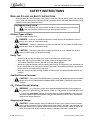
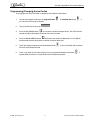
®
IDC 255 PROGATE DRIVE THRU
Service Manual
Release Date: June 27, 2006
Publication Number: 621057419SER
Revision Date: NA
Revision: A
Visit the IMI Cornelius web site at www.cornelius.com for all your Literature needs.
IDC 255 PROGATE DRIVE THRU
SERVICE MANUAL
The products, technical information, and instructions contained in this manual are subject
to change without notice. These instructions are not intended to cover all details or variations of the equipment, nor to provide for every possible contingency in the installation,
operation or maintenance of this equipment. This manual assumes that the person(s)
working on the equipment have been trained and are skilled in working with electrical,
plumbing, pneumatic, and mechanical equipment. It is assumed that appropriate safety
precautions are taken and that all local safety and construction requirements are being
met, in addition to the information contained in this manual.
To inquire about current revisions of this and other documentation or for assistance with
any Cornelius product contact:
www.cornelius.com
800-238-3600
Trademarks and copyrights:
Aurora, Cornelius, FlavorFusion, Hydro Boost, Optifill, Pinnacle, and Vanguard are registered trademarks of IMI Cornelius Inc.
This document contains proprietary information and it may not be
reproduced in any way without permission from Cornelius.
Printed in U.S.A.
Copyright © 2006, All Rights Reserved, IMI Cornelius, Inc.
TABLE OF CONTENTS
Safety Instructions . . . . . . . . . . . . . . . . . . . . . . . . . . . . . . . . . . . . . . . . . . . . . . . . . . . .
Read and Follow all Safety Instructions . . . . . . . . . . . . . . . . . . . . . . . . . . . . . . . . . .
Recognize Safety Alerts . . . . . . . . . . . . . . . . . . . . . . . . . . . . . . . . . . . . . . . . . . .
Different Types of Alerts . . . . . . . . . . . . . . . . . . . . . . . . . . . . . . . . . . . . . . . . . . .
Safety Tips . . . . . . . . . . . . . . . . . . . . . . . . . . . . . . . . . . . . . . . . . . . . . . . . . . . . .
Qualified Service Personnel . . . . . . . . . . . . . . . . . . . . . . . . . . . . . . . . . . . . . . . .
CO2 (Carbon Dioxide) Warning . . . . . . . . . . . . . . . . . . . . . . . . . . . . . . . . . . . . .
Shipping And Storage . . . . . . . . . . . . . . . . . . . . . . . . . . . . . . . . . . . . . . . . . . . . .
1
1
1
1
1
1
1
1
Unit Specification . . . . . . . . . . . . . . . . . . . . . . . . . . . . . . . . . . . . . . . . . . . . . . . . . . . . .
Description . . . . . . . . . . . . . . . . . . . . . . . . . . . . . . . . . . . . . . . . . . . . . . . . . . . . . . . .
Valve Configurations . . . . . . . . . . . . . . . . . . . . . . . . . . . . . . . . . . . . . . . . . . . . . . . . .
Specification . . . . . . . . . . . . . . . . . . . . . . . . . . . . . . . . . . . . . . . . . . . . . . . . . . . . . . .
Progate 2 Features . . . . . . . . . . . . . . . . . . . . . . . . . . . . . . . . . . . . . . . . . . . . . . .
Progate Portion Ice Control Features . . . . . . . . . . . . . . . . . . . . . . . . . . . . . .
Lid Dispenser . . . . . . . . . . . . . . . . . . . . . . . . . . . . . . . . . . . . . . . . . . . . . . . .
Straw Holder . . . . . . . . . . . . . . . . . . . . . . . . . . . . . . . . . . . . . . . . . . . . . . . . .
Lid Dispenser Maintenance . . . . . . . . . . . . . . . . . . . . . . . . . . . . . . . . . . . . . . . . . . . .
Progate 2 Control Box Operation . . . . . . . . . . . . . . . . . . . . . . . . . . . . . . . . . . . . . . .
Portion Control Box Functions . . . . . . . . . . . . . . . . . . . . . . . . . . . . . . . . . . . . . .
Programming (Changing) the Ice Portion . . . . . . . . . . . . . . . . . . . . . . . . . . . . . .
Agitation Time . . . . . . . . . . . . . . . . . . . . . . . . . . . . . . . . . . . . . . . . . . . . . . . . . . .
Programming (Changing) the Agitation Time . . . . . . . . . . . . . . . . . . . . . . . . . . .
Ice Portion Bar . . . . . . . . . . . . . . . . . . . . . . . . . . . . . . . . . . . . . . . . . . . . . . . . . .
2
2
2
2
3
3
3
3
3
4
4
4
6
7
8
Diagrams . . . . . . . . . . . . . . . . . . . . . . . . . . . . . . . . . . . . . . . . . . . . . . . . . . . . . . . . . . . . 9
Cold Plate . . . . . . . . . . . . . . . . . . . . . . . . . . . . . . . . . . . . . . . . . . . . . . . . . . . . . . . . . 9
7 Intelli Valves and 1 Variety Valve . . . . . . . . . . . . . . . . . . . . . . . . . . . . . . . . . . . 9
8 Intelli Valves or 8 UFB-1 Valves . . . . . . . . . . . . . . . . . . . . . . . . . . . . . . . . . . . 10
E – Board Off Cycle Agitation Adjustments . . . . . . . . . . . . . . . . . . . . . . . . . . . . . . . 11
Electrical Schematic . . . . . . . . . . . . . . . . . . . . . . . . . . . . . . . . . . . . . . . . . . . . . . . . 12
Main Electrical Box Assembly . . . . . . . . . . . . . . . . . . . . . . . . . . . . . . . . . . . . . . . . . 13
Interconnect Schematic . . . . . . . . . . . . . . . . . . . . . . . . . . . . . . . . . . . . . . . . . . . . . . 14
Maintenance . . . . . . . . . . . . . . . . . . . . . . . . . . . . . . . . . . . . . . . . . . . . . . . . . . . . . . . .
Daily (or as required) . . . . . . . . . . . . . . . . . . . . . . . . . . . . . . . . . . . . . . . . . . . . . . . .
Checking CO2 Supply . . . . . . . . . . . . . . . . . . . . . . . . . . . . . . . . . . . . . . . . . . . .
Replenishing CO2 Supply . . . . . . . . . . . . . . . . . . . . . . . . . . . . . . . . . . . . . .
Checking for CO2 and water leak . . . . . . . . . . . . . . . . . . . . . . . . . . . . . . . . . . .
Dispensing Valves . . . . . . . . . . . . . . . . . . . . . . . . . . . . . . . . . . . . . . . . . . . . . . .
Cleaning Dispensing Valve . . . . . . . . . . . . . . . . . . . . . . . . . . . . . . . . . . . . .
Monthly . . . . . . . . . . . . . . . . . . . . . . . . . . . . . . . . . . . . . . . . . . . . . . . . . . . . . . . . . .
Beverage System (if applicable) . . . . . . . . . . . . . . . . . . . . . . . . . . . . . . . . . . . . . . .
Cold Plate . . . . . . . . . . . . . . . . . . . . . . . . . . . . . . . . . . . . . . . . . . . . . . . . . . . . .
Sanitize syrup lines, B–I–B Systems . . . . . . . . . . . . . . . . . . . . . . . . . . . . . . . . .
15
15
15
15
15
15
15
16
16
16
16
Yearly . . . . . . . . . . . . . . . . . . . . . . . . . . . . . . . . . . . . . . . . . . . . . . . . . . . . . . . . . . . 17
Water Pump Maintenance (or after water system disruption) . . . . . . . . . . . . . . 17
Cleaning CO2 Gas Check Valve . . . . . . . . . . . . . . . . . . . . . . . . . . . . . . . . . . . . 17
Service . . . . . . . . . . . . . . . . . . . . . . . . . . . . . . . . . . . . . . . . . . . . . . . . . . . . . . . . . . . . .
Merchandiser Removal . . . . . . . . . . . . . . . . . . . . . . . . . . . . . . . . . . . . . . . . . . . . .
Control Box Removal . . . . . . . . . . . . . . . . . . . . . . . . . . . . . . . . . . . . . . . . . . . . . . .
Main Electrical Box Access . . . . . . . . . . . . . . . . . . . . . . . . . . . . . . . . . . . . . . . . . . .
Ice Chute Removal . . . . . . . . . . . . . . . . . . . . . . . . . . . . . . . . . . . . . . . . . . . . . . . . .
Motor Removal . . . . . . . . . . . . . . . . . . . . . . . . . . . . . . . . . . . . . . . . . . . . . . . . . . . .
18
18
19
19
20
21
Troubleshooting . . . . . . . . . . . . . . . . . . . . . . . . . . . . . . . . . . . . . . . . . . . . . . . . . . . . .
Power Light Off . . . . . . . . . . . . . . . . . . . . . . . . . . . . . . . . . . . . . . . . . . . . . . . . . . . .
No Ice Dispense in Manual Mode . . . . . . . . . . . . . . . . . . . . . . . . . . . . . . . . . . . . . .
No Ice Dispense in Automatic Mode . . . . . . . . . . . . . . . . . . . . . . . . . . . . . . . . . . . .
Beverage Not Dispensing . . . . . . . . . . . . . . . . . . . . . . . . . . . . . . . . . . . . . . . . . . . .
Flat Drinks . . . . . . . . . . . . . . . . . . . . . . . . . . . . . . . . . . . . . . . . . . . . . . . . . . . . . . . .
No Carbonated Water . . . . . . . . . . . . . . . . . . . . . . . . . . . . . . . . . . . . . . . . . . . . . . .
22
22
23
24
25
26
27
IDC 255 Progate Drive Thru Service Manual
SAFETY INSTRUCTIONS
READ AND FOLLOW ALL SAFETY INSTRUCTIONS
Read and follow all safety instructions in this manual and on the machine (decals, labels, and laminated
cards). Read and understand all applicable OSHA (Occupation Safety and Health Administration) safety
regulations before operating the machine.
Recognize Safety Alerts
This is the safety alert symbol. When you see it in this manual or on the machine be
alert to the potential of personal injury or damage to the machine.
Different Types of Alerts
There are 3 types of safety alerts:
DANGER — Indicates an immediate hazardous situation which if not avoided WILL result in
serious injury, death, or equipment damage.
WARNING — Indicates a potentially hazardous situation which, if not avoided, COULD result in
serious injury, death, or equipment damage.
CAUTION — Indicates a potentially hazardous situation which, if not avoided, MAY result in
minor or moderate injury or equipment damage.
Safety Tips
•
•
•
•
Carefully read all safety messages in this manual and safety signs on the machine.
Keep safety signs in good condition and replace missing or damaged safety signs.
Learn how to operate the machine and how to use the controls properly.
Do not let anyone operate the machine without proper training. This appliance is not intended for use
by very young children or infirm persons without supervision. Young children should be supervised to
ensure that they do not play with the appliance.
• Keep your machine in proper working condition and do not allow unauthorized modifications to the
machine.
Qualified Service Personnel
CAUTION — Only trained and certified electrical, plumbing and refrigeration technicians should
service this unit. ALL WIRING AND PLUMBING MUST CONFORM TO NATIONAL AND LOCAL
CODES.
CO2 (Carbon Dioxide) Warning
WARNING — CO2 Displaces Oxygen. Strict Attention must be observed in the prevention of
CO2 gas leaks in the entire CO2 and soft drink system. If a CO2 gas leak is suspected, particularly
in a small area, immediately ventilate the contaminated area before attempting to repair the leak.
Personnel exposed to high concentration of CO2 gas will experience tremors which are followed
rapidly by loss of consciousness.
Shipping And Storage
CAUTION — Before shipping, storing, or relocating the Unit, syrup systems must be sanitized
and all sanitizing solution must be purged from the syrup systems. All liquids, after sanitizing, must
be purged from the unit. A freezing ambient environment will cause residual sanitizing solution or
water remaining inside the Unit to freeze resulting in damage to the internal components.
© 2006, IMI Cornelius Inc.
-1-
Publication Number: 621057419SER
IDC 255 Progate Drive Thru Service Manual
UNIT SPECIFICATION
DESCRIPTION
The Ice Drink Cornelius (IDC) series of dispensers solves your ice and beverage service needs in a
sanitary, space saving, economical way. Designed to be manually filled with ice from any remote ice–
making source, these dispensers will dispense cubes (up to 1–1/4 inch in size), cubelets, and
compressed (not flaked). In addition, the units include beverage faucets, a cold plate, an internal
carbonator tank and an external pump for the carbonator, and are designed to be supplied direct from
syrup tanks with no additional cooling required.
VALVE CONFIGURATIONS
•
IDC 255 Progate Drive Thru Unit with 7 Intelli Valves and 1 Variety Valve
•
IDC 255 Progate Drive Thru Unit with 8 Intelli Valves
•
IDC 255 Progate Drive Thru Unit with 8 UFB-1 Valves
SPECIFICATION
Model Descriptions
Unit Weight
Ice Storage
Maximum Number of Faucets
Built in Cold Plate
Electrical
Dimensions
CO2 Operating Pressure
Water
Publication Number: 621057419SER
IDC 255
B=Beverage
C=Coldplate
H=Internal Carb
P=Progate
Z=No Drip Tray
368 Pounds
255 Pounds
10
Yes
120/1/60
9.3 Amps of Total Unit Draw
OR
220/1/50
4.7 Amps of Total Unit Draw
Width 29.90 inch (.76 m)
Height 39.75 inch (1.0 m)
Depth 36.90 inch (.94 m)
75-psig (max)
100 psi (7 bar) maximum static pressure.
40 psi (2.8 bar) minimum dynamic pressure.
3/8” minimum water line recommended.
-2-
© 2006, IMI Cornelius Inc.
IDC 255 Progate Drive Thru Service Manual
36.901
39.750
PCX
OUT OF RATIO
LABEL
20.756
CORNELIUS
LOGO
UNIT
SERIAL NUMBER
30.000
FIGURE 1
Electrical Connections: 6 ft long power cord with 3-prong plug attached to dispenser.
Power Requirements: 9.3 amps at 120 volts dedicated power supply.
Water Supply Requirements: 100 psi (7 bar) maximum static pressure 40 psi (28 bar) minimum
dynamic pressure. 3/8” minimum water line recommended.
CO2 Requirements: 100 psi max to unit regulated to 35 psi (2.4 bar) to Progate 2 ice gate system, 75
psi (5.2 bar) carbonator.
Progate 2 Features
Progate Portion Ice Control Features
• 4 Programmable ice dispense sizes
•
Automatic/Manual Ice Dispense Modes
•
Unit Power On/Off Switch
•
Programmable Agitation Time
Lid Dispenser
• 4 lid dispenser locations on the unit
•
3 Separate removable lid dispensers for small/medium, large, and extra large lids
Straw Holder
• Holds up to 140 regular sleeved straws
LID DISPENSER MAINTENANCE
The lid dispensers are manufactured out of materials that can survive chlorine-based cleaners and warm
water <100°F. Ensure that the parts are thoroughly dried before refilling with lids.
NOTE: Lid dispenser parts should not be soaked in the powersoak washing machine as this will
result in the parts getting scratched. Instead the dispenser parts should be rinsed in warm soap
water and then dried.
© 2006, IMI Cornelius Inc.
-3-
Publication Number: 621057419SER
IDC 255 Progate Drive Thru Service Manual
PROGATE 2 CONTROL BOX OPERATION
Portion Control Box Functions
The portion control box on the PROGATE 2 has several functions including dispensing 4 programmed ice
portions for 4 cup sizes, programming and a manual dispense mode.
1
2
1. MAIN POWER ON/OFF
3
6
2. AGITATOR PUSH ON
3. MODE SWITCH MANUAL/PROGATE
4. PROGRAM BUTTON
7
4
5. ICE PORTION DISPENSE BUTTONS
5
6. ICE PORTION BAR
7. PROGATE ON LIGHT
8. PORTION SIZE UP/DOWN KEYS
8
1.
2.
3.
4.
5.
6.
7.
8.
Main Power ON OFF: Turns power to the entire machine off. Lights Orange when ON.
Agitator Push ON: Turns on agitator and opens ice gate allowing continuous dispense. This button
will turn green in the manual mode and be off in PROGATE automatic. This button will also agitate
in the automatic mode but not dispense ice.
Mode Switch Manual/Progate: Turns on agitator and opens ice gate allowing unlimited ice portion.
Program Button: The programming button is used with cup size button enabling the user to enter
the portion programming mode to adjust the ice portions. The programming button is used with the
directional arrow buttons to adjust the agitation time.
Ice Portion Dispense Buttons: Used to dispense the appropriate ice portion. Can also be used in
conjunction with the program button to program a portion size.
Ice Size Program Bar: The program bar is only active in the program mode as a visual aid in
setting the portion size.
Light: On start up of the unit or during a mode change (Manual to Progate) this light turns orange
to inform the user that the unit is going through a self diagnostic test. On completion of this test the
light turns green to inform the user that the machine is ready to dispense. If the light remains solid
on red and the unit is not dispensing any ice when an ice portion is pressed this should generate a
service call. During ice dispense if there is insufficient ice in the ice chute then the light turns red
instantaneously to inform the user that there is insufficient ice. Once the user releases the portioned
button then the red light goes out.
Portion Up/Down Buttons: The program bar is only active in the program mode to change the ice
dispense program size.
Publication Number: 621057419SER
-4-
© 2006, IMI Cornelius Inc.
IDC 255 Progate Drive Thru Service Manual
Programming (Changing) the Ice Portion
To change the size of any of the four ice dispense sizes follow the steps below.
1.
To enter the program mode press the Program Button
the same time and hold for 5 seconds.
2.
The Ice Portion Bar will come on
3.
Press the UP ARROW button
to increase the amount of dispensed ice. The LED will move
towards the right indicating the Ice Portion has been increased.
4.
Press the DOWN ARROW button
to decrease the amount of dispensed ice. The LED will
move towards the left indicating the Ice Portion has been decreased.
5.
To exit the program mode press the Desired Size button
will return to the dispense mode.
6.
Place a cup under the ice chute and press the just programmed dispense size button
amount dispense amount is not the desired amount repeat the process.
© 2006, IMI Cornelius Inc.
-5-
and Desired Size button
at
or wait 10 seconds and the control
If
Publication Number: 621057419SER
IDC 255 Progate Drive Thru Service Manual
Agitation Time
The software coding for the progate system involves a direct relationship between the dispense time and
the agitation time.
Dispense Time (mS)
Agitation Ratio
Agitation Time (mS)
50
10
500
70
10
700
90
10
900
110
10
1100
130
10
1300
150
10
1500
170
10
1700
190
10
1900
210
10
2100
230
10
2300
Dispense Time (mS)
Agitation Ratio
Agitation Time (mS)
50
16
800
70
16
1120
90
16
1440
110
16
1760
130
16
2080
150
16
2400
170
16
2720
190
16
3040
210
16
3360
230
16
3680
Dispense Time (mS)
Agitation Ratio
Agitation Time (mS)
50
28
1400
70
28
1960
90
28
2520
110
28
3080
130
28
3640
150
28
4200
170
28
4760
190
28
5320
210
28
5880
230
28
6440
The relationship is expressed below.
Agitation Time (AT) = Dispense Time (DT) x Agitation Ratio2 (RA)
Publication Number: 621057419SER
-6-
© 2006, IMI Cornelius Inc.
IDC 255 Progate Drive Thru Service Manual
The agitation time equals the dispense time multiplied by the agitation ratio. The user is given the
flexibility to change the agitation ratio thereby altering the agitation time in order to ensure that the ice
chute is always filled with ice for all the different ice types.
2
10
12
14
16
18
20
22
24
26
28
FIGURE 2
Programming (Changing) the Agitation Time
1.
Simultaneously Press and hold for 3 seconds, the
2.
buttons
to enter the programming mode.
The LED meter turns ON once the programming mode is entered. Visual feedback of ratio/agitation
3.
button and also both direction arrow
time is obtained from the visual programming LED
. The LED meter shows the
existing agitation ratio enabling the user to.
Vary the agitation time using the directional arrow buttons. Left to decrease and right direction
arrow button to increase.
© 2006, IMI Cornelius Inc.
-7-
Publication Number: 621057419SER
IDC 255 Progate Drive Thru Service Manual
Ice Portion Bar
The portion bar is used to determine the amount of time programmed for each size button. Each button
has a minimum and maximum amount of time that can be programmed. If a button cannot be adjusted to
the size desired use another button to get the desired results.
=20mS
“S” Small
50mS
230mS
80mS
260mS
150mS
330mS
230mS
410mS
“M” Medium
“L” Large
“XL” XLarge
FIGURE 3
Publication Number: 621057419SER
-8-
© 2006, IMI Cornelius Inc.
W2
1
W4
2
3
2
4
5
3
6
4
-9S1
W3
CW
NOTES:
PLUMBING TO FITTINGS OF DIFFERENT DIAMETER
MAY BE ACCOMPLISHED BY SPLICING THE TUBE AND
USING APPROPRIATE CONNECTORS
W1
CW
1
PW
TO PROGATE
SYSTEM
S2
W2
PW
SYRUP 1 OUT
(SINGLE TOWER)
6
S3
5
4
S6
S7
9
6
PW
COLDPLATE
2
1 12 11 10
S4 S5
3
5
7
8
S8
7
INCLUDED WITH UNIT
ELECTRICAL-BOX
S9
7
CW
S10
8
8
9
10
9
11
W4
PW
W3
PRIMARY REGULATOR
110 PSIG
SECONDARY
REGULATOR
60 PSIG
FOR SYRUP BIBS
12
10
CW
RECIRC
IN
W2
PW
SYRUP 2
OUT
© 2006, IMI Cornelius Inc.
PW = PLAIN WATER
CO2
CYLINDER
IN
W3
W1
CW = CARBONATED WATER
PRE-CHILLED WATER
RECIRC
OUT
FILTER REGULATOR
PRESSURE
REGULATOR
OR BOOSTER
PUMP MAY BE
REQUIRED
WATER FILTER
CITY WATER
PUMP & MOTOR ASY
SHUT-OFF
VALVE
IDC 255 Progate Drive Thru Service Manual
DIAGRAMS
COLD PLATE
The beverage assembly for the unit comprises of 7 Intelli Valves and 1 Variety valve, 8 Intelli Valves, or 8
UFB-1 valves. Attached are the cold plate diagrams showing the each of the connections.
7 Intelli Valves and 1 Variety Valve
TO BE POST-CHILLED
FIGURE 4
Publication Number: 621057419SER
- 10 NOTES:
PLUMBING TO FITTINGS OF DIFFERENT DIAMETER
MAY BE ACCOMPLISHED BY SPLICING THE TUBE AND
USING APPROPRIATE CONNECTORS
W1
W2
CW
1
1
W4
2
RECIRC
IN
3
2
4
5
3
6
4
S1
W3
PW
TO PROGATE
SYSTEM
CW
REG A&W OUT
(SINGLE TOWER)
S2
W2
PW
6
S3
5
4
S6
9
S7
COLDPLATE
2
1 12 11 10
S4 S5
3
8
S8
7
CW
INCLUDED WITH UNIT
5
ELECTRICAL-BOX
7
8
9
6
10
11
7
12
W4
8
PW
W3
PRIMARY REGULATOR
110 PSIG
SECONDARY
REGULATOR
60 PSIG
FOR SYRUP BIBS
REG A&W OUT
DUAL TOWER
CW
SYRUP 2
OUT
W2
PW
DIET A&W OUT
DUAL TOWER
Publication Number: 621057419SER
PW = PLAIN WATER
W3
CO2
CYLINDER
IN
W1
CW = CARBONATED WATER
PRE-CHILLED WATER
RECIRC
OUT
FILTER REGULATOR
PRESSURE
REGULATOR
OR BOOSTER
PUMP MAY BE
REQUIRED
WATER FILTER
CITY WATER
PUMP & MOTOR ASY
SHUT-OFF
VALVE
IDC 255 Progate Drive Thru Service Manual
8 Intelli Valves or 8 UFB-1 Valves
TO BE POST-CHILLED
FIGURE 5
© 2006, IMI Cornelius Inc.
IDC 255 Progate Drive Thru Service Manual
E – BOARD OFF CYCLE AGITATION ADJUSTMENTS
When Ice is not being dispensed from the machine such as during off hours it is essential to move or
agitate the ice to keep it from clumping and to replenish the ice in the cold plate. The amount of time the
agitator runs and the time between the agitation cycles can be adjusted depending on ice type or
application. The settings for this function are located on the E-Board found in the E-BOX. To access the
board to be adjusted refer to sections 5.1 and 5.3. Using a screwdriver follow the diagram below and set
the agitator for the desired settings.
MOTOR ON TIME
3.5
4
4.5
5
1
.5
E-BOARD AGITATION TIMER
3
2.5
2
1.5
ON
TIME
OFF
TIME
2
OFF TIME
2.5
OFF
TIME
FULL CW - 5 SECONDS
ON
TIME
FULL CCW - 0.5 SECONDS
3
HRS
HRS
HRS
1.5
FULL CCW - 10 MINUTES
FULL CW - 3 HOURS
HRS
1
HR
30
10
MIN
MIN
FIGURE 6
Manufacturer Recommended Agitation Settings
Model
Ice Fill/Ice Type
175, 215,
&255, 300,
B, BC
Motor ON Time Motor OFF time
Manual/Hard Ice (Cube)
4 Seconds
1 Hour
Automatic (Top-Mount Ice
Maker/Hard Ice (Cube)
0.5 Seconds
20 Minutes
Manual & Automatic/
Cornelius Chunklet,
Scotsman & Hoshizaki
Compressed Ice
0.5 Seconds
3 Hours
B - Beverage C-Coldplate
© 2006, IMI Cornelius Inc.
*NO FLAKED ICE*
- 11 -
Publication Number: 621057419SER
BLK
1
3
5
7
BLUE
BLK
KEY SWITCH
SW2
(100 VA)
T1
LEFT
TOTAL FLEX
SOLENOID BLOCK
RIGHT
TOTAL FLEX
SOLENOID BLOCK
- 12 -
BLK
CR3
3 4
P1-3
BLK
0
1
CR3
8 6
CR2
BLK
YLW
CR3
1
0
OFF CYCLE AGITION MOTOR
BY PASS
P1-1
ENABLE/DISABLE
3
AUTO/MANUAL
MODE SWITCH
SW1
2
CR1
4
P1-2
2
25 VAC SECONDARY
120 VAC PRIMARY
18AWG
WHT
P1-4
18AWG
BLK
LINE VOLTAGE
120VAC
50/60 HZ
YLW18AWG
ICE CHUTE
COVER SWITCH
S2
YLW CR1
BLK
YLW
1
0
(50 VA)
RED
P1-3
BLK
1
BLUE
Publication Number: 621057419SER
RED
11
WHT
BLK
YLW 18AWG
CARBONATOR PROBES
25
S3
ON/OFF
12
WHT
BLK
RED
GRN/YEL
LIGHT
WHT
GRN
ORG
PURP
YLW
BLK
6
7
8
4
5
1
2
3
PURP
BLK
J1
BOARD KEYPAD AGITATION TIMER
PROGATE 2
GND
AGITATOR CONTROL
ICE GATE
24 VAC1
24 VAC2
PB1
LIGHT
P1-4
BOARD AGITATION/ CARBONATOR
6203141825
BALLEST L2
BALLEST L1
HEATER L2
HEATER L1
"CARB MOTOR GND"
J3
"L2 CARB MOTOR"
WHT
GRN
1
2
3
1
2
1
2
1
2
1
2
1
2
1
2
1
2
1
2
1
2
1
2
J5
J2
J1
"L1 CARB MOTOR"
"AGITITATOR GND"
"L2 AGITITATOR"
"L1 AGITITATOR"
CARBONATOR
PROBES
YLW
J4
XFORMER L2
XFORMER L1
GND
L2 PWR
RED 1
BLK 2
WHT 3
4
5
GRN/YEL
L1 PWR
P1-7
ORG
C1
ORG
BLK
CR2
6 8
BLK
BLK
P1-6
WHT
BLK
GRN/YLW
BLU
BRN
GRN/YLW
CR1
BRN 8 6
YLW
BALLEST
BLK
3
GRN3
PB1
4
4 ORG
L
RIGHT
KEYPAD
M
LEFT
MANUAL MODE DISPENSE
S
STARTER
WHT
BLK
ICE AGITATION
HEATER
CARBONATOR
XL
PROGRAM
YLW
PURP
P1-5
PURP
FLOURENCENT
LIGHTS
( OPTIONAL )
ICE AGITATION
COMPONENTS LOCATED IN CONTROL BOX
WHT
BLK
HT
MTR
MTR
SOL1
PNEUMATIC
VALVE TIMED SOLENOI
IDC 255 Progate Drive Thru Service Manual
ELECTRICAL SCHEMATIC
YLW
18AWG
YLW
18AWG
© 2006, IMI Cornelius Inc.
© 2006, IMI Cornelius Inc.
AIR INPUT
- 13 RETRACT
P/N 70959
TSN NUTS
6 PLCS
PUR
YEL
BLK
BLK
YLW
YLW
BLK
0
CR1
1
8
2
6
4
P1
0
CR2
1
BLK
8
2
6
4
CAPACITOR
AGITATOR L2
YLW
NO/NC RELAY
0
BLK
1
YLW
J2
3
BLK
P/N 620052685
CONTROL BOX BRACKET
P/Ns: 07052009 - SCREW
0720603-NUT
J5
7
CR3
RED
AGITATOR EARTH
2
4
RED
TRANSFORMER
BLU
EARTH IN
6
8
P/N 620314825
TIMER BOARD
P/N 60569001
RELAY NO
2 PLCS
P/N 30774
CAPAC MOTOR AGIT
P/N 325192000
BUSHING 1.093
P/N 30514
STRAP CAPAC
TERMINAL
BOARD
P/N 92305
LABEL
CARB MOTOR EARTH
PUSH
PNEUMATIC SOLENOID
P/N 620314025
RELAY NO NC
P/N 620313711
SOLENOID ASY
P/N 720500795
X-FORMER
P/N 620314152
BOX ELECTRIC PROGATE
BLU
WHT
5
L2 HEATER
4 3
2
L2 XFORMER
1
L1 XFORMER
TO PNUEMATIC CYLINDER
KEY SWITCH
P/N 620052503
BRACKET
P/N 325192000
BUSHING
P/N 70217
8-32 SCEW SS
P/N 31107
TERMINAL BOARD
L2 BALLEST
L1 IN
L2 IN
POWER
CORD
IDC 255 Progate Drive Thru Service Manual
MAIN ELECTRICAL BOX ASSEMBLY
L1 HEATER
L1 BALLEST
CARB MOTOR
L2 CARB MOTOR
AGITATOR
J1
BLK MODE SW
BLK
WHT
YLW
PUR
Publication Number: 621057419SER
AIR INPUT
Publication Number: 621057419SER
0
BLK
WHT
YLW
BLK
PUR
- 14 11
24
12
25
P/N
620314765
SW3
4
1
J1
PB1
8
3
3
P1
P1
X1
2
6
4
INTERFACE BOARD
4
X2
0
CR1
1
BLK MODE SW
P/N 32229
HARNESS ASSY.
AC INPUT
P/N 620317414
HARNESS CHUTE COVER
DISABLE SWITCH
NO/NC RELAY
YLW
PUSH
YLW
1
YLW
J4
2
1
3
4
1 2 3
0
5
8
2
6
4
SW1
CR2
1
BLK
P/N 620317417
HARNESS CONTROL BOX/
MAIN ASSEMBLY
CAPACITOR
AGITATOR L2
P/N 620314527
HARNESS SENSOR ICECHUTE
DISABLE SWITCH
RETRACT
YEL
BLK
3
YLW
J2
7
CR3
BLK
J5
TO PNUEMATIC CYLINDER
KEY SWITCH
PUR
BLK
AGITATOR EARTH
GND
WHT
5
L2 HEATER
4 3
1
L2 BALLEST
L1 IN
L2 IN
P/N 620313669
JUMPER 18" BLACK
2
L2 XFORMER
P/N 620317452
CARB MOTOR
24 VAC1
BLK
EARTH IN
2
4
RED
L1 XFORMER
24 VAC2
CARB MOTOR EARTH
6
8
RED
TRANSFORMER
BLU
L1 HEATER
ICE GATE
TERMINAL
BOARD
BLU
L1 BALLEST
AGITATOR CONTROL
PNEUMATIC SOLENOID
P/N 620316455
HARNESS CARB PROBE
P/N 620314720
HARNESS POWER CORD
POWER
CORD
P/N 620316455
HARNESS AGITATOR MOTOR
P/N 30794
HARNESS MOTOR HEATER
P/N 620316456
CARBONATOR MOTOR
IDC 255 Progate Drive Thru Service Manual
INTERCONNECT SCHEMATIC
L2 CARB MOTOR
AGITATOR
J1
FIGURE 7
© 2006, IMI Cornelius Inc.
IDC 255 Progate Drive Thru Service Manual
MAINTENANCE
The following dispenser maintenance should be performed at the intervals indicated:
DAILY (OR AS REQUIRED)
Remove foreign material from vending area drip tray to prevent drain blockage.
Clean vending area. Check for proper water drainage from the vending area drip tray.
Checking CO2 Supply
Make sure CO2 cylinder regulator assembly 1800-psi gage indicator is not in shaded (“change CO2
cylinder”) portion of the dial. If so, the CO2 cylinder is almost empty and must be replaced.
Replenishing CO2 Supply
NOTE: When indicator on the 1800-psi gage is in the shaded (“change CO2 cylinder”) portion of
the dial, CO2 cylinder is almost empty and should be changed.
1.
Fully close (clockwise) the CO2 cylinder valve.
2.
Slowly loosen the CO2 regulator assembly coupling nut allowing CO2 pressure to escape, then
remove the regulator assembly from the empty CO2 cylinder.
3.
Unfasten safety chain and remove the empty CO2 cylinder.
WARNING: To avoid personnel injury and/or property damage, always secure the CO2 cylinder with
a safety chain to prevent it from falling over. Should the valve become accidently damaged or
broken off, a CO2 regulator can cause serious personnel injury.
4.
Position the full CO2 cylinder and secure with a safety chain.
5.
Make sure gasket is in place inside the CO2 regulator assembly coupling nut, then install the
regulator assembly on the CO2 cylinder.
6.
Open (counterclockwise) the CO2 cylinder valve slightly to allow the lines to slowly fill with gas, then
open the valve fully to back-seat the valve (back-seating the valve prevents gas leakage around the
valve shaft).
Check CO2 connections for leaks. Tighten any loose connections.
7.
Checking for CO2 and water leak
Check the Unit for CO2 and water leaks and if found, call a qualified Service Person to repair as
necessary.
Dispensing Valves
Refer to addendum supplied with the unit that is applicable to the manufacturer of the valves installed
on the unit.
Cleaning Dispensing Valve
1.
Remove nozzle assembly (contains Inner Nozzle) from dispensing valve. Separate the inner nozzle
from the nozzle and wash the two parts in warm water.
2.
Remove the bottom plate by releasing the two snap-fit clips. Remove the lever from the bottom
plate and wash the bottom plate and the lever in warm water.
3.
Reassemble the lever into the bottom plate and return the bottom plate to the valve. Be sure the
rear tabs are properly secured.
© 2006, IMI Cornelius Inc.
- 15 -
Publication Number: 621057419SER
IDC 255 Progate Drive Thru Service Manual
4.
Return the inner nozzle to the nozzle and replace the assembly to the valve.
SNAP FIT CLIP
BOTTOM
PLATE P/N
1903
SNAP FIT
CLIP
SNAP FIT
CLIP
REAR
TAB
SNAP FIT
CLIP
O
F
F
INNER
NOZZLE
NOZZLE
MONTHLY
Clean and sanitize the hopper interior and beverage system, if applicable (see CLEANING
INSTRUCTIONS).
BEVERAGE SYSTEM (IF APPLICABLE)
WARNING: Disconnect Power Before Cleaning! Do no use metal scrapers, sharp objects, or
abrasives on the ice storage hopper, top cover and the agitator disk, as damage may result. Do not
use solvents or other cleaning agents, as they may attack the plastic material.
•
Soap solution – Use a mixture of mild detergent and warm (100oF) potable water.
•
Sanitizing solution – Dissolve 2 packets (4 oz.) Stera Sheen Green Label into 2 gallons of warm (80100oF) water to ensure 200 ppm of available chlorine.
•
Cleaning tank – Fill clean, empty tank with a mixture of mild detergent and five (5) gallons of warm
potable water (120oF).
CAUTION: When pouring liquid into the hopper, do not exceed the rate of 1/2 gallon per minute.
Cold Plate
1.
2.
3.
4.
5.
6.
7.
8.
Remove splash panel.
Remove or move the plastic cold plate cover to expose the cold plate.
Locate and remove any debris from the drain trough. Check that the drain holes are not clogged.
Pour small amount of soap solution through cold plate openings in hopper.
Using a cloth, wash down the surfaces of the cold plate and plastic cover with soap solution.
Install and properly position the access covers on the cold plate.
Install the splash panel in the reverse order it was removed.
Rinse cold plate surface by pouring potable water through hopper openings.
Sanitize syrup lines, B–I–B Systems
1.
2.
3.
Remove all the quick disconnects from all the B–I–B containers.
Fill a suitable pail or bucket with soap solution.
Submerge all disconnects (gas and liquid) in the soap solution and then clean them using a nylon
bristle brush. (Do not use a wire brush). Rinse with clean water.
Publication Number: 621057419SER
- 16 -
© 2006, IMI Cornelius Inc.
IDC 255 Progate Drive Thru Service Manual
4.
5.
6.
7.
8.
9.
Using a plastic pail, prepare approximately five (5) gallons of sanitizing solution.
Rinse the B–I–B disconnects in the sanitizing solution.
Sanitizing fittings must be attached to each B–I–B disconnect. If these fittings are not available, the
fittings from empty B–I–B bags can be cut from the bags and used. These fittings open the
disconnect so the sanitizing solution can be drawn through the disconnect.
Place all the B–I–B disconnects into the pail of sanitizing solution. Operate all the valves until the
sanitizing solution is flowing from the valve. Allow sanitizer to remain in lines for fifteen (15) minutes.
Remove the nozzle and syrup diffuser from each valve and clean them in a soap solution. Rinse
with clean water and reassemble the nozzle and syrup diffuser to the valve.
Remove the sanitizing fittings from the B–I–B disconnects and connect the disconnects to the
appropriate
B–I–B container. Operate the valves until all sanitizer has been flushed from the system and syrup
is flowing freely.
YEARLY
Water Pump Maintenance (or after water system disruption)
The water pump water strainer screen and the liquid dual check valve must be inspected and cleaned at
least once a year under normal circumstances and after any water system disruption (plumbing work,
earthquake, etc.). Call a qualified Service Person to inspect and clean the strainer screen and the liquid
dual check valve.
Cleaning CO2 Gas Check Valve
The CO2 gas check valve, located on the carbonated water tank, must be inspected and serviced at least
once a year under normal conditions and after any CO2 system servicing disruption. Call a qualified
Service Person to inspect and clean the CO2 gas check valve.
© 2006, IMI Cornelius Inc.
- 17 -
Publication Number: 621057419SER
IDC 255 Progate Drive Thru Service Manual
SERVICE
MERCHANDISER REMOVAL
1.
Remove all lid holders and straw dispenser.
FIGURE 8
FIGURE 9
2.
Remove screws holding merchandiser to
control box.
3.
Grab panel by sides, lift up to disengage locking tabs and rotate forward past.
FIGURE 10
FIGURE 11
Publication Number: 621057419SER
FIGURE 12
- 18 -
© 2006, IMI Cornelius Inc.
IDC 255 Progate Drive Thru Service Manual
CONTROL BOX REMOVAL
1.
With cover removed locate and remove 4
screws from Control box flange.
FIGURE 13
2.
Pull box forward exposing control board,
wiring and switches.
FIGURE 14
MAIN ELECTRICAL BOX ACCESS
1.
Remove screw-locking cover to electrical
box.
FIGURE 15
2.
Lift cover up and then rotate forward.
FIGURE 16
© 2006, IMI Cornelius Inc.
- 19 -
Publication Number: 621057419SER
IDC 255 Progate Drive Thru Service Manual
ICE CHUTE REMOVAL
1.
Remove 4 nuts attaching ice chute to
hopper.
FIGURE 17
2.
Disconnect ice chute switch harness located behind the control box.
FIGURE 18
FIGURE 19
3.
Pull assembly away form hopper. Do not
loose or damage gasket. If damaged or
missing replace.
4.
Pull ice chute assembly out of splash
panel and disconnect the CO2 lines.
NOTE: Mark the CO2 lines to avoid improper
assembly.
FIGURE 20
5.
View of underside of ice chute assembly
showing gate and pneumatic cylinder.
FIGURE 21
Publication Number: 621057419SER
- 20 -
© 2006, IMI Cornelius Inc.
IDC 255 Progate Drive Thru Service Manual
MOTOR REMOVAL
Heater, Agitation
Motor, & Gear Box
NOTE: Apply anti seizing lubricant to the
threads of mounting bolts when service is
required.
Heater Spring
Motor
Mounting
Screws
FIGURE 22
© 2006, IMI Cornelius Inc.
- 21 -
Publication Number: 621057419SER
IDC 255 Progate Drive Thru Service Manual
TROUBLESHOOTING
POWER LIGHT OFF
POWER LIGHT OFF
Is the unit plugged
into a socket
Yes
Are there other
equipments on the
same circuit
Yes
1. Remove all other equipment
from the machine circuit.
2. Install a new dedicated circuit
for the machine.
No
No
1. Plug unit into a socket.
Publication Number: 621057419SER
1. Check the external power supply
breakers.
2. Open the e box and check that the
power cord wires (black and white) are
connected to the e - board.
3. Check the connector between control
box and the e box.
- 22 -
© 2006, IMI Cornelius Inc.
IDC 255 Progate Drive Thru Service Manual
NO ICE DISPENSE IN MANUAL MODE
NO ICE DISPENSE IN MANUAL
MODE
1. Check the connector between the
control box and the E-Box.
Yes 2. Check relay 3 in the E-Box for
power (terminal 3&4).
3. Check pneumatic solenoid.
Is the
machine inlet
pressure greater
than 35 PSI
No
1. Check air supply shut off outside the E-Box
2. Check air supply line
3. Check pneumatic cylinder for free movement
Yes
Is manual/
automatic rocker switch
in the manual position
Is lighted green push
button on
Yes
Yes
Is ice
present in the
ice chute
No
No
1. Set the machine to
manual mode by pressing
the manual/automatic rocker
switch
No
Do drink valves
operate
1. Check the
connector between
Yes
the control box and
the E - Box
Does the agitator run
when push button is
pressed
No
1. Check key lock out
switch
2. Check transformer for
power
3. Check all connections
from the terminal board to
the push button
Is ice being
dispensed in
auto mode
1. Check the electrical
connection from the
portion control board to
the solenoid valve
2. Check pneumatic
solenoid
3. Check relief valve
No
1. Check the red LED on the
E - Box board
2. Ensure that relay two in the
E-Box is activating
No
Is Ice chute
switch enabled or
disabled
Enabled
1. Check relay 1 in the E-Box.
The small post on the right hand
side should be retracted
Disabled
1. Check magnetic switch in switch housing
2. Check for magnet in ice chute cover
3. Validate magnet distance from magnetic switch
for activation to occur
4. Check ice chute disable switch ensuring that relay
1 is activating
5. Check transformer outputs wiring
© 2006, IMI Cornelius Inc.
- 23 -
Publication Number: 621057419SER
IDC 255 Progate Drive Thru Service Manual
NO ICE DISPENSE IN AUTOMATIC MODE
NO ICE DISPENSE IN AUTOMATIC MODE
Can you
dispense ice from all the ice
sizes
Some sizes
1. Check all connections to
portion control pc board
1. Check the connector between
the control box and the E-Box.
2. Check terminals 6 and 8 on
relay 3 in the E-Box.
3. Check the pneumatic solenoid
None of the Sizes
Yes
Is the green
power light on the
keypad on
Yes
Is there ice
present in the ice
chute
Check for proper air
pressure going to the
filter regulator in the EBox (35PSI or greater)
Yes
Is the air
pressure to the filter
regulater above
35PSI
No
No
Does the agitator
work when the green push
button is pressed
Yes
1. Ensure that the ice
maker is functioning
properly.
2. Check ice in hopper
ensuring that it is loose
No
1. Check air supply
shut off outside the EBox.
2. Check air supply to
the unit.
3. Check gate cylinder
for free movement.
1. Check the red LED on the E-Box pc board.
2. Ensure that relay 2 in the E-box is activated
Do the
drink valves
operate
Yes
1. Check the
connector between
the control box and
the E-Box.
Does manual mode
work
Yes
1. Check mode selector switch.
2. Ensure relay 2 is activated.
No
No
1. Check key lock out switch.
2. Check transformer for power.
3. Check all electrical connections.
Is ice
chute switch
disabled
Yes
No
1. Check magnetic switch in chute
housing.
2. Check for magnet in chute cover.
3. Validate magnet distance from ice
chute disable switch.
4. Check ice chute disable switch.
5. Ensure that relay 1 is activated.
6. Check transformer power output to
control circuit
1. Relay 1 in the E-Box
should be activated by small
post on the side of the relay
being retracted
Publication Number: 621057419SER
- 24 -
© 2006, IMI Cornelius Inc.
IDC 255 Progate Drive Thru Service Manual
BEVERAGE NOT DISPENSING
BEVERAGE NOT DISPENSING
Is the key switch
on/off
On
Is
there power on
the line side of the
transformer
Yes
Is
there power on the
load side of the
transformer
Yes
Off
No
No
1. Check the key switch
1. Check the transformer
connections to the E-Board in
the E-Box.
2. Check the E - Board in the EBox ensuring that power is
being supplied to the board.
© 2006, IMI Cornelius Inc.
- 25 -
1. Check the transformer.
2. Change the transformer.
1.Check the wire harness from the
beverage valves to the terminal board.
2. Check the beverage dispense valve to
ensure that they are functioning.
3. Change beverage valve.
4. Check the water line to the valve and the
syrup line to the valve.
Publication Number: 621057419SER
IDC 255 Progate Drive Thru Service Manual
FLAT DRINKS
Yes
FLAT DRINK(S)
Is the
drink temperature
above 40 degrees
Fahrenheit
1. Replace
carbonator
pump
Yes
Is CO2
being supplied to
the carbonator tank
Yes
No
No
Is there
ice on the cold
plate
No
1. Check CO2 supply tank.
2. Check CO2 supply lines.
3. Change CO2 tank
Yes
Is the
CO2 pressure in
the system
correct
1. Adjust CO2 pressure
accordingly
Yes
Does
the carbonator
cycle when a 20oz
drink is dispensed
No
1. Refer to
carbonator flow
chart.
1. Check ice coverage
on the cold plate
No
1. Fill the hopper with
ice.
2. Dispense some ice to
ensure that the agitator
spreads ice on the cold
plate.
Publication Number: 621057419SER
- 26 -
© 2006, IMI Cornelius Inc.
IDC 255 Progate Drive Thru Service Manual
NO CARBONATED WATER
NO CARBONATED WATER
Does the
carbonator pump start
when the unit is
turned on
No
1. Check the carbonator pump
connection to the E-Board in the EBox.
Yes
Is the
incoming water
restricted
Yes
No
Is there
power connection to
the carbonator
pump
Yes
Is the
pump motor
running
Yes
1. Replace Carbonator
pump.
2. Check Y fitting on the
total flex manifold
No
No
1. Check whether or not there is
power across the carbonator power
cord on the E-Board in the E-Box.
2. Change carbonator power cord on
the E-Board in the E-Box
© 2006, IMI Cornelius Inc.
1. Restore the
recommended water flow
- 27 -
1. Replace carbonator
pump
Publication Number: 621057419SER
IDC 255 Progate Drive Thru Service Manual
Publication Number: 621057419SER
- 28 -
© 2006, IMI Cornelius Inc.
IMI Cornelius Inc.
www.cornelius.com