1
INSTALLATION
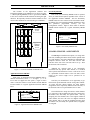
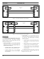
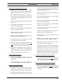
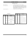
MASTR III Power Supply/Audio
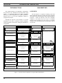
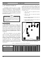
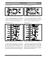
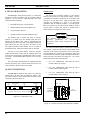
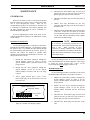
If the GTI unit is to be connected to a MASTR III
repeater channel, connect a 19B803830P1 cable from the
male 1x6-pin Molex connector on the back of the GTI
(marked "POWER/AUDIO") to P4 on the MASTR III
repeater T/R Shelf backplane, and to P801 on the repeater
power supply, as shown in Figure 30. Note that the power
supply end of the cable comes with pins attached to wires,
but no connector shell. These pins are to be inserted into the
existing connector shell already connected to P801 on the
power supply. Insert the pin on the red wire into pin
position 3 and the pin on the black wire into pin position 6.
GTI
T/R Shelf Backplane
POWER/AUDIO
Tx Audio
Rx Audio
PTT
Gnd
+12 Vdc
P4
1
2
4
5
6
#24 BRN
#24 BLU
#24 YEL
#24 BLK
1
6
5
2
MIC_HI
INTRCM_AUDIO
LOCAL_PTT
Power Supply
P801
#22 BLK
#22 RED
3.
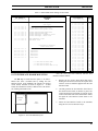
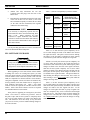
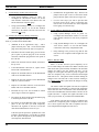
Remove pin 3 (attached to the two W/Y/BN colored
wires) from the longer connector, P40, and insert the
pin back into the same connector, but now as pin 4.
4.
Cut the short loop of white wire between pins 1 and 2 in
the longer connector, P40.
5.
Remove pin 1 from the longer connector, P40, and
insert the pin back into the same connector, but now as
pin 3.
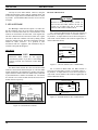
NOTE
Once the MASTR II or IIe repeater harness has
been modified per steps 4 and 5, a GTI unit must
be connected to the repeater harness at all times
to complete the audio loop of the repeater. If the
GTI unit ever needs to be removed, you must
reconnect the jumper cut in step 4. Because of
the pin change in step 5, the jumper will be
needed between pins 2 and 3.
AGND
Existing Connector
19B803830P1 Cable
LBI-39076B
6
3
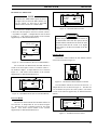
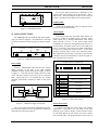
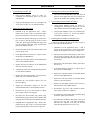
Plug this rearranged P40 into the male 1x6-pin Molex
connector (marked "POWER/AUDIO") on the back of the
GTI. See Figure 31.
Neg
Pos
GTI
T/R Shelf Backplane
P40
POWER/AUDIO
Figure 30 - MASTR III Connections
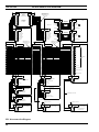
MASTR II or IIe Power Supply/Audio
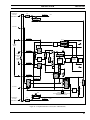
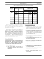
If the GTI unit is to be connected to a MASTR II or IIe
repeater channel, the existing 19C320811G15 or G16
harness for the MASTR II or IIe repeater channel must be
modified.
The modification involves two existing
connectors on the harness: P40 - a 1x6-pin Molex connector,
and P41 - a 1x2-pin Molex connector. These connectors
will be found secured to the harness as it goes to J1201,
J1202, J1203, and J1204 on the backplane of the repeater.
Use the following procedure to rearrange the wires from
these two connectors into the single connector, P40, and
then connect it to the GTI unit:
1.
2.
Remove pin 1 from the shorter connector, P41, using a
small screwdriver or scribe to depress the tongue of the
pin in the open slot in the side of the connector while
you pull gently on the wires going to the pin. Insert the
pin into the longer connector, P40, as pin 6.
Remove pin 2 from the shorter connector, P41, and
insert the pin back into the longer connector, P40, as
pin 5.
Rx Audio
2
Tx Audio
PTT
3
4
Gnd
+12 Vdc
5
6
P3
W-BK
J1203
7
TRANS AUDIO HI
11
TRANS AUDIO LO
W-BK-R
W-Y-BR
Rec/Exc Door
P8
Modified Part of
19C320811G15 or G16 Harness
W-Y-BR
J933
6
TRANS AUDIO HI
5
TRANS AUDIO LO
6
5
Power Supply
4
P40 3
2
1
P801
P9
#22 BLK
#22 RED
5
Neg
3
Pos
Figure 31 - MASTR II & IIe Connections
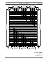
PCM/Data Bus
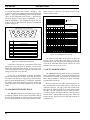
The PCM/Data bus is made up of a PCM/Data bus
termination plug and one or more 12-pair shielded cables
daisy-chained between each GTI, the Master GTI, and the
optional IAM (if present). These cables have a stackable
25