1
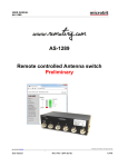
m crob t USER MANUAL RC-1216H RC-1216H Web based remote control for SteppIR, ACOM-2000A, Expert 1K-FA, Elecraft KPA500 and Rotators User Manual Microbit 2.0 AB 2010. All rights reserved Ba-RC1216H-PA9 a User manual Rev. PA9 – 2014 Sept 10 1 of 79 m crob t USER MANUAL RC-1216H Table of contents Statement of Conditions .............................................................................. 4 General Description ..................................................................................... 5 Step by step RC-1216 H setup ..................................................................... 7 Hardware .................................................................................................... 9 Front ........................................................................................................... 9 Back .......................................................................................................... 11 Configuration with Microbit Setup Manager .............................................. 12 FW/HW ...................................................................................................... 13 FW update .................................................................................................. 14 Setup......................................................................................................... 15 Net info ...................................................................................................... 16 Initial IP setup .......................................................................................... 17 Configuration with WEB-interface ............................................................. 21 IP Settings.................................................................................................. 23 Dynamic DNS setting ................................................................................... 26 Remoterig dynamic dns service ..................................................................... 27 DynDNS dynamic DNSservice ........................................................................ 29 Application firmware upgrade ........................................................................ 31 Bootloader firmware upgrade ........................................................................ 32 Restart device ............................................................................................. 32 Networks and Firewalls ............................................................................. 32 Portforwarding ............................................................................................ 33 RC-1216H setup for SteppIR Antenna Control ........................................... 34 Installation of the RC-1216H for SteppIR control .............................................. 35 Settings for SteppIR .................................................................................. 36 RC-1216H setup for ACOM 2000A control .................................................. 39 Installation with ACOM-2000A ....................................................................... 40 ACOM-2000A with ACOM-2000S Antenna Switch ............................................. 41 ACOM-2000A – 230VAC Power switching ........................................................ 42 Settings for ACOM-2000A .......................................................................... 43 RC-1216H setup for Expert 1K-FA control ................................................. 48 Installation with Expert 1K-FA ....................................................................... 49 Edxpert 1K-FA – 230VAC Power switching ....................................................... 50 Microbit 2.0 AB 2010. All rights reserved Ba-RC1216H-PA9 a User manual Rev. PA9 – 2014 Sept 10 2 of 79 m crob t USER MANUAL RC-1216H Settings for Expert 1K-FA ......................................................................... 51 Error and Warnings ...................................................................................... 54 AUX SW1 Relay ........................................................................................... 56 Serial port server ........................................................................................ 57 Using Setup Microbit Setup Manager to create a virtual serial port ..................... 58 RC-1216H setup for Elecraft KPA500 control ............................................. 62 Installation with Elecraft KPA500 ................................................................... 63 Elecraft KPA-500 – 230VAC Power switching ................................................... 64 Settings for Elecraft KPA500 ..................................................................... 64 Error and Warnings ...................................................................................... 69 AUX SW1 Relay ........................................................................................... 69 RC-1216H setup for Rotator control .......................................................... 70 Installation example with Prosistel or AlfaSpid ................................................. 71 Rotator – 230VAC Power switching ................................................................ 72 AlfaSpid Power switching .............................................................................. 72 Settings for Rotator control....................................................................... 73 Appendix D - Technical Data ..................................................................... 77 Appendix E - Safety and Regulatory Information ...................................... 78 FCC Statement ............................................................................................ 78 Safety Notice .............................................................................................. 78 Disclaimer .................................................................................................. 79 FCC / CE - Declaration of conformity .............................................................. 79 Microbit 2.0 AB 2010. All rights reserved Ba-RC1216H-PA9 a User manual Rev. PA9 – 2014 Sept 10 3 of 79 m crob t USER MANUAL RC-1216H Statement of Conditions In the interest of improving internal design, operational function, and/or reliability, Microbit 2.0 AB reserves the right to make changes to the product described in this document without notice. Microbit does not assume any liability that may occur due to the use or application of the product(s) or circuit layout(s) described herein. All parts of the software are property of Microbit 2.0 AB. The hardware design, schematics PCB layout, concept, graphics, user manual, etc. are property of Microbit 2.0 AB. The device may not be disassembled, copied or reversed engineered. Copyright © 2010,2011 Microbit 2.0 AB All rights reserved. Microbit 2.0 AB 2010. All rights reserved Ba-RC1216H-PA9 a User manual Rev. PA9 – 2014 Sept 10 4 of 79 m crob t USER MANUAL RC-1216H General Description The RC-1216H is developed especially for remote control of Amateur radio accessories like Antennas, Power Amplifiers and rotators via the Internet in a user-friendly and cost-effective way. Lot of radio accessories are designed to be controlled from a PC via a serial port (RS232). Serial ports are not very convenient to transfer over the Internet. The RC-1216H acts as PC against the connected equipment at the same time as it shows a more user friendly web based user interface for the operator. The web interface is much more convenient to use over the Internet as no special software need to be installed in the PC and it can be reach from any Internet connected PC or other device like smartphones, pads etc. around the world. For the moment the Remote control RC-1216H can be configured to control SteppIR antennas, the ACOM-2000A Power Amp, Expert K-FA Power Amp, Elecraft KPA500 Power Amp, Prositel and AlfaSpid Rotators, Yaesu rotators with GS-232B interface and other Green Heron controlled rotators. The Remote control unit RC-1216H system is connected to the Internet primarily via 10 or 100 Mbit Ethernet and fixed connections like DSL, cable and WLAN or 3G/4G Mobile systems. The RC-1216H is easily configured via modern USB and WEB based user interfaces. Microbit 2.0 AB 2010. All rights reserved Ba-RC1216H-PA9 a User manual Rev. PA9 – 2014 Sept 10 5 of 79 m crob t USER MANUAL RC-1216H SteppIR Control ACOM-2000A Control Expert 1K-FA Control The RC-1216 can be configured to remote control a SteppIR antenna. The controls are the same as on the SDA-100 control box. You can use Retract, Calibrate, Bi-directional, 180 degree switch etc. Frequency adjustment can be done manual or automatic. The RC-1216 can be configured to remote control a ACOM-2000A Power amplifier. The controls and indicators are almost the same as on ACOM-2000A control Panel (RCU) so you will recognize them immediately. The RC-1216 can be configured to remote control a Expert 1K-FA Power amplifier. The daily used controls and indicators are available direct from the web interface. The RC-1216H also act as a serialport server so you can connect with the original PC-program in parallel if you have to do some setups. Elecraft KPA500 Control Rotator Control The RC-1216 can be configured to remote control a Elecraft KPA500 Power amplifier. The daily used controls and indicators are available direct from the web interface. The RC-1216 can be configured to remote control rotators. At this moment it support Prosistel rotators with the D-type control box, and AlfaSpid rotators, rotators controlled by Green Heron control box, Yaesu rotators with GS-232B serial interface and other rotators with serial interfaces using the DCU-1 protocol Microbit 2.0 AB 2010. All rights reserved Ba-RC1216H-PA9 a User manual Rev. PA9 – 2014 Sept 10 6 of 79 m crob t USER MANUAL RC-1216H Step by step RC-1216 H setup Below follows a recommendation about how to proceed when setting up the system. 1. Spend some time to read thru this user manual to get familiar with the product. 2. Apply 12V DC (good stabilized power) to the unit. 3. Connect the unit with a CAT5 patch cables to the same Ethernet switch or router as your PC which you will use to setup the system is connected. 4. Download the Microbit Setup Manager and the latest firmware from http://www.remoterig.com to your PC. Follow the instructions about how to install the Microbit Setup Manager (see chapter Configuration with Microbit Setup Manager). 5. Find out how your network is configured and configure the RC-1216H to fit into your network (see chapter Initial IP Setup) with the Microbit Setup Manager. This has to be done with both units. 6. Check the installed firmware version. If the one you downloaded from Remoterig is newer, update the unit with the new firmware. (see chapter FW/HW about how to update). 7. When you have configured the unit to fit into your network, Start your Web browser and connect to the unite by entering the IP-address. If you get in contact with the internal web server everything is OK. 8. Make the basic software configuration for your system which is described the later in this user manual. 9. Prepare the cables needed for your PA, Antenna or Rotator according to the cable drawings provided in this user manual and the manual of the connected equipment. Double check your home made cables with an ohm meter before connecting them to the units to prevent harm of any equipment. Microbit do not take any responsibility of damaged units or connected equipment. 10. After preparing the cables connect them to the controlled equipment. Connect the power to all equipment. Check with your web browser again that you are in contact with unit and can control the connected equipment. 11. When everything works as it should on your local network it’s time to setup your Internet router so you can reach the unit from the outside world over the Internet. If you already have other equipment that you remote control you can go direct to 14 as you don’t need to use a separate Dynamic DNS service. 12. The first thing is to determine if your Internet Service Provider (ISP) are providing you with a fixed or dynamic IP-address. Fixed IP:s are rare so you probably have a dynamic IP-address if you are not paying extra for a fixed one. A dynamic IP is no problem but you need to use a dynamic DNS service. You can use Remoterigs free dynamic DNS service or a DynDNS account. New DynDNS account are no longer free. Microbit 2.0 AB 2010. All rights reserved Ba-RC1216H-PA9 a User manual Rev. PA9 – 2014 Sept 10 7 of 79 m crob t USER MANUAL RC-1216H For detailed information about Dynamic DNS services see the Dynamic DNS chapters under Configuration with WEB-Interface. 13. Configure the units Dynamic DNS settings (see chapter Dynamic DNS Setting). 14. Now it’s time to configure your remote router. We recommend that you first enable the remote configuring of your router, you may need it later. After that’s done configure port forwarding (see chapter Network and Firewalls). When this is done your remote control unit should be reachable over the Internet. 15. When back at the Control QTH try to browse to the Dynamic DNS address “Own host name” you registered and entered into the remote control unit. You should get in contact with the RC:s internal web server exactly as it was local, remember to use :port number after the dyndns address if you have changed the webserver port from 80 for example http://sm2oan.mine.nu:8000. Enjoy the remote controlling. Microbit 2.0 AB 2010. All rights reserved Ba-RC1216H-PA9 a User manual Rev. PA9 – 2014 Sept 10 8 of 79 m crob t USER MANUAL RC-1216H Hardware Front RS-232 The RS232 connector is used for serial communication with the controlled equipment. Eg the Power Amplifier, SteppIR control box, Rotator Control box etc. It has a male connector configured like a PC. The communication parameter is set via the web interface. RS-232 Pin no 1 2 3 4 5 6 7 8 9 RS-232 Interface (9-pol D-sub male) RXD (in) TXD (out) DTR (*Only used for Expert available after 2014-june-01) GND (* the DTR signal can be added easily by the user in older version) Microbit 2.0 AB 2010. All rights reserved Ba-RC1216H-PA9 a User manual Rev. PA9 – 2014 Sept 10 9 of 79 m crob t USER MANUAL RC-1216H ON LED Green flashing light is indicating normal status. USB The USB-interface is used to initially set up the IP parameters. It can also be used for downloading new software (can also be done via the WEB-interface). A USB-cable is included with the product. ETHERNETand LNK The unit can be connected to both 10 and 100 Mbit/s Ethernet based TCP/IP network. The RC126H can be configured for different connection types for Ethernet port, Auto, 10HDX, 10FDX, 100HDX, 100FDX and Auto-with-preferred-10FDX. Default is Auto-with-preferred10FDX which works best in most cases. Pin no Ethernet (RJ45) 1 2 3 4 5 6 7 8 LNK Out [+] Out [-] In [+] In [-] Green LED indicates link OK flashing LED indicates traffic Yellow LED indicates speed = 100Mbit/s (off = 10MBits/s) Microbit 2.0 AB 2010. All rights reserved Ba-RC1216H-PA9 a User manual Rev. PA9 – 2014 Sept 10 10 of 79 m crob t USER MANUAL RC-1216H Back PWR The RC-1216H is powered via the PWR connector (2.1/5.5 mm) with 10-18 VDC. A DC-cord is included with the product. 12V DC Pin no PWR + - + 10-18 VDC (centre) GND PWR SW Inside the box is a Relay (230V/16A) connected to the socket block. Safety regulations says that max 50V can be switched with this Relay output. The Relay can are rated 10A DC at 30V or 2A DC at 40V. This means that if you want to Switch On/Off a 230V Power amplifier etc. you must control an external relay with this output. AUX SW1 Inside the box is a Relay (230V/16A) connected to the socket block. Safety regulations says that max 50V can be switched with this Relay output. The Relay can are rated 10A DC at 30V or 2A DC at 40V. This means that if you want to Switch On/Off a 230V Power amplifier etc. you must control an external relay with this output. Microbit 2.0 AB 2010. All rights reserved Ba-RC1216H-PA9 a User manual Rev. PA9 – 2014 Sept 10 11 of 79 m crob t USER MANUAL RC-1216H Configuration with Microbit Setup Manager The initial settings of the network parameters are easiest done with the Microbit Setup Manager. The Setup Manager is a software which runs under Windows on a PC and connects to the RC via USB (an USB cable is supplied with the RC-1216H).The Setup Manager can be used for: IP Settings and verification o IP-address o Netmask o Gateway o DNS o DHCP Firmware upgrade o Application o Bootloader o Factory default reset Start with downloading the Microbit Setup Manager from the homepage www.remoterig.com. Install the Setup Manager by following the instructions which shows up. If you have an older Windows version where Netframework 2.0 is not installed, the installer will guide you through the installation of Netframework. When you have finished the installation a new shortcut to Microbit Setup Manager will show up on the desktop. Click on the icon to start Microbit Setup Manager Connect your RC-1216H to 12V and connect the USB-cable between your computer and the USB jack on the front of the RC-1216H. Windows will automatically install the necessary drivers. When it's done the text in the bottom field will change from "1216H not connected" to "1216H-connected" which is an indication that you are in connection with the unit. Microbit 2.0 AB 2010. All rights reserved Ba-RC1216H-PA9 a User manual Rev. PA9 – 2014 Sept 10 12 of 79 m crob t USER MANUAL RC-1216H FW/HW Click on the "Get" button and the version of the firmware will show up in the upper window. Go to the page www.remoterig.com and under downloads you can find the latest firmware. If there is a newer firmware available download it to your desktop, unzip it. Change to the "FW-update" tab. Microbit 2.0 AB 2010. All rights reserved Ba-RC1216H-PA9 a User manual Rev. PA9 – 2014 Sept 10 13 of 79 m crob t USER MANUAL RC-1216H FW update Click on the "Select file" button and browse to the file with the new firmware, it should be something like “1216H-CRC_v1.23_2011-10-04.bin” depending on the version and release date. When you have selected the file click on the "Update" button and the update process will start, the text in the bottom field will change to "Updating firmware". Attention -- Do not interrupt the update process in any way! After about a 1 minute the update is finished and the RC will restart. When the text "RCconnected" shows up again in the lower field of the Microbit Setup Manager, you can change to the "FW/HW" tab and check software version. Microbit 2.0 AB 2010. All rights reserved Ba-RC1216H-PA9 a User manual Rev. PA9 – 2014 Sept 10 14 of 79 m crob t USER MANUAL RC-1216H Setup A new window wills pop-up with the basic IP settings. Change the settings so they fit into your local network and press the "Save" button to save the new settings. The RC will restart again and when the text "1216H-connected" shows up again in the lower field of the SetupManager, you can click on the "Setup" button again to verify the changes. Microbit 2.0 AB 2010. All rights reserved Ba-RC1216H-PA9 a User manual Rev. PA9 – 2014 Sept 10 15 of 79 m crob t USER MANUAL RC-1216H Net info Click on the “Get” button to read the IP setting currently in use by the RC-1216H. Microbit 2.0 AB 2010. All rights reserved Ba-RC1216H-PA9 a User manual Rev. PA9 – 2014 Sept 10 16 of 79 m crob t USER MANUAL RC-1216H Initial IP setup The default Ip settings from the factory is 192.168.0.236. The net mask is 255.255.255.0, gateway and DNS is 192.168.0.1. To be able to contact the RC-1216H via the network you must configure the units to fit into your home network. You can check your network configuration from your PC. On the start menu select Run. In the Run dialog box enter cmd. You will get a DOS-window. At the DOS-promt enter ipconfig. Then you will get the needed information: Your PC IP address in this example is 192.168.0.101 this means that the IP of the RC-1216H must have IP:s in the area 192.168.0.2 to 192.168.0.255. Microbit 2.0 AB 2010. All rights reserved Ba-RC1216H-PA9 a User manual Rev. PA9 – 2014 Sept 10 17 of 79 m crob t USER MANUAL RC-1216H The Netmask is 255.255.255.0 the Netmask in the RC-1216H should be the same The Default gateway 192.168.0.1 the Gateway and DNS server(*) in the RC should be the same In this case all the default IP setting will be OK. (*) In most cases the Gateway and the DNS server is the same and the IP of the router. Microbit 2.0 AB 2010. All rights reserved Ba-RC1216H-PA9 a User manual Rev. PA9 – 2014 Sept 10 18 of 79 m crob t USER MANUAL RC-1216H In another network, this is the result of the ipconfig command. Your PC IP address in this example is 192.168.128.10 this means that the IP of the RC-1216H must have IP:s in the area 192.168.128.2 to 192.168.128.255. The Netmask is 255.255.128.0 this the Netmask in the RC should be the same The Default gateway is 192.168.128.1 the Gateway in the RC-1216H should be the same In this case you must change the IP:s of the RC. Use the Microbit Setup Manager to change the IP settings. Select the Setup tab click on the “Get Setup” button and enter the IP addresses in the Setup info dialog box. Microbit 2.0 AB 2010. All rights reserved Ba-RC1216H-PA9 a User manual Rev. PA9 – 2014 Sept 10 19 of 79 m crob t USER MANUAL RC-1216H Microbit 2.0 AB 2010. All rights reserved Ba-RC1216H-PA9 a User manual Rev. PA9 – 2014 Sept 10 20 of 79 m crob t USER MANUAL RC-1216H Configuration with WEB-interface Before you can use your RC-1216H you must configure it. The unit will have the default IP addresses 192.168.0.236. The net mask is 255.255.255.0. The configuration is easiest done via the web interface. Be aware of that your PC must be in the same net e.g. having an IPnumber between 192.168.0.2 and 192.168.0.254 and not be the same as the RC-1216H. If the default IP-address the RC not fit your network please use the PC-program Microbit Setup Manager to change the IP-addresses via USB. Select setup page from the links on the left side and edit the parameters. After each setup pages is finished press Submit to temporary store the new settings. When you do that a new red Apply changes button appears on the pages. You can now change parameters on other pages but the new settings will not take effect until you press Apply changes. When you do that the unit will reboot and start up with the new settings. If you change your mind after clicking on submit you can click on Restart device on the left to restart the device without changing any settings. Microbit 2.0 AB 2010. All rights reserved Ba-RC1216H-PA9 a User manual Rev. PA9 – 2014 Sept 10 21 of 79 m crob t USER MANUAL RC-1216H The info page shows some static information about the RC-1216H as firmware revision etc. and also the basic IP-configuration. Microbit 2.0 AB 2010. All rights reserved Ba-RC1216H-PA9 a User manual Rev. PA9 – 2014 Sept 10 22 of 79 m crob t USER MANUAL RC-1216H IP Settings The IP Settings menu is used to setup the initial IP parameters needed for the unit to connect to the IP network. Down below the settings are described more in details. Microbit 2.0 AB 2010. All rights reserved Ba-RC1216H-PA9 a User manual Rev. PA9 – 2014 Sept 10 23 of 79 m crob t USER MANUAL RC-1216H Parameter Setting Unit ID (Banner) Text, whatever you want, that will be shown at the top of the web-page (within brackets). Used to identify different units. “empty” (default) “text” Select between a fixed IP address and DHCP. Fixed IP address is recommended. No (default) Yes IP-address (only when fixed IP-address is used) 192.168.0.236 (default) nnn.nnn.nnn.nnn Net mask (only when fixed IP-address is used) 255.255.255.0 (default) nnn.nnn.nnn.nnn Gateway (only when fixed IP-address is used) 192.168.0.1 (default) nnn.nnn.nnn.nnn DNS-address (only when fixed IP-address is used) 192.168.0.1 (default) nnn.nnn.nnn.nnn Sets the port number for the Internal webserver. This port number often has to be changed if port 80 already is used by other equipment. 80 (default) Type of Ethernet connection: Auto Auto, prefer 10 Mbit (default) 10HDX* 10FDX* 100HDX* 100FDX* DHCP IP Netmask Gateway Dns server Web server port Eth-type Auto prefer 10 Mbit is default as more speed is not needed and the emissions from a 10 Mbit LAN is much less than from a 100 Mbit LAN (*) If you use fixed settings you must have a managed switch where you can set the same setting. Microbit 2.0 AB 2010. All rights reserved Ba-RC1216H-PA9 a User manual Rev. PA9 – 2014 Sept 10 24 of 79 m crob t USER MANUAL RC-1216H Web page user Web page pwd Enable password protection for the web by entering a username (this field) and a password (next field). If this field is empty the RC will not ask for password. Some of the pages are still accessible but no editing is possible. “empty” (default) “username” Password for the web pages and telnet connection. “empty” (default) “password” Microbit 2.0 AB 2010. All rights reserved Ba-RC1216H-PA9 a User manual Rev. PA9 – 2014 Sept 10 25 of 79 m crob t USER MANUAL RC-1216H Dynamic DNS setting The RC-1216H has a Dynamic DNS client to be used when the Internet Service Provider (ISP) uses dynamic IP addresses instead of fixed IP address. The RC-1216H supports our own free Remoterig dynamic DNS service and DynDNS which is not free anymore. You can choose to use one of them. The Dynamic DNS client checks what IP address your router has got from the ISP and sends the information to the Dynamic DNS:s service DNS server. When using Dynamic DNS you enter "Own host name" instead of an IP address in the web browser and you don't need to bother if the IP address at the Remote site changes. If you already have a Dynamic DNS account registered for any equipment connected to the same router at the remote site, you do not need to register any specific for the RC-1216H. Microbit 2.0 AB 2010. All rights reserved Ba-RC1216H-PA9 a User manual Rev. PA9 – 2014 Sept 10 26 of 79 m crob t USER MANUAL RC-1216H Remoterig dynamic dns service The Remoterig dynamic dns service only support equipment from Remoterig and Microbit like the RC-1216H, RRC-1258 and the WebSwitch 1216H etc. The Remoterig dynamic dns service do not need any registration it’s automatically generated based on the serial number on the equipment. To activate the Remoterig dynamic dns client select “ddns.remoterig.com” from the drop down on the Dynamic DNS settings page. Also select a DNS check interval, if your IP address change often you can select a low value, if it goes month between the changes you can select a higher value. After that click on “Submit” and “Apply changes”, the RRC will restart. Microbit 2.0 AB 2010. All rights reserved Ba-RC1216H-PA9 a User manual Rev. PA9 – 2014 Sept 10 27 of 79 m crob t USER MANUAL RC-1216H After the RC-1216H has restarted go back to the Dynamic DNS settings page. You will now see that the settings Own hostname, Username and Password are automatically generated. The only important information is the Own host name, copy the whole row, this is the information you should put into your web browsers address field when you contact the unit in the future. Store it as a Bookmark as it is difficult to remember. No more registration is needed. Remember that DNS address like this is only for use when you connect over the internet, as long as you are operating on you own LAN use the IP address. Microbit 2.0 AB 2010. All rights reserved Ba-RC1216H-PA9 a User manual Rev. PA9 – 2014 Sept 10 28 of 79 m crob t USER MANUAL RC-1216H DynDNS dynamic DNSservice The RC1216H also supports the commercial dynamic DNS service DynDns. If your router has a DynDNS client you can also use that one, and do not activate more than one DynDNS client at the same LAN segment. DynDNS do not accept multiple updates from same IP. The DynDNS client checks what IP address your router has got from the ISP and sends the information to DynDNS:s DNS server. When using DynDNS you enter "Own host name" instead of an IP address in we browsers address field and you don't need to bother if the IP address at the remote QTH changes. You need to register an account at http://www.dyndns.com/services/dns/dyndns/ and get a domain name. There are other providers of the same service but RC-1216H only supports DynDNS or Remoterig ddns. Parameter Setting Microbit 2.0 AB 2010. All rights reserved Ba-RC1216H-PA9 a User manual Rev. PA9 – 2014 Sept 10 29 of 79 m crob t USER MANUAL RC-1216H Dynamic DNS check interval Dynamic DNS host name Own host name Username Password Sets how often the external IP address of your router should be checked, value in minutes: Off (Dynamic DNS client disabled) 10 20 30 40 50 60 180 600 1440 Sets which DNS service you will use ddns.remoterig.com (our own free service) members.dyndns.org (commercial service) Domain name registered at DynDNS.com. Example: my-radio-site.ham-radio-op.net Dynamic DNS account username. Dynamic DNS account password. Microbit 2.0 AB 2010. All rights reserved Ba-RC1216H-PA9 a User manual Rev. PA9 – 2014 Sept 10 30 of 79 m crob t USER MANUAL RC-1216H Application firmware upgrade The application firmware can be updated over the Internet via the web interface when bugs are fixed and/or new functionality is implemented. You don't have to be where the RC1216H is to do the updates. Download the new firmware from www.remoterig.com and save the file on your computer (it has a name like 1216H-CRC_v1.38_2011-09-04.bin). Connect to the RC-1216H and select 'Application-upgrade'. Then click on the 'Browse' button and select the file with the new firmware. After that you click on the 'Upgrade' button and the new firmware will be transferred and saved into the RC. When the firmware is updated the RC will restart. Note -- Do not interrupt the upgrade process in any way. Wait a minute or two then connect to the RC-1216H again and select 'Info' and verify that the Software version is updated. If it looks like its not updated empty the web browser cache, to prevent it from showing an old cached page. The update NEVER fails but the browser is a common problem. Microbit 2.0 AB 2010. All rights reserved Ba-RC1216H-PA9 a User manual Rev. PA9 – 2014 Sept 10 31 of 79 m crob t USER MANUAL RC-1216H Bootloader firmware upgrade This follows the same steps as the application firmware upgrade procedure above. Restart device Restart device can be used if you want to reset and restart the RC-1216H without saving any changes (before apply changes) or just for ordinary reset. Networks and Firewalls One of the major obstacles when trying to remotely control something is the fact that the Internet Service Provider (ISP) forces us to use dynamic IP addresses. We can never know, from time to time, which IP address our modem / firewall / router has on its outside interface (the IP address you will try to connect to). Most people use NAT routers that translates IP addresses on the inside (your little LAN) to one common IP address on the outside using port conversion. At the remote end the router must be configured so that port 80 (default settings) is directed to the RC-1216 which should have a static IP address. If you have other remote controlled equipment connected to the router port 80 is probably already in use and you need to change the webserver port from 80 to something else. In the example below where we have setup the Linksys router we have used port 8000. You will also need to register the RC-1216H to DynDNS (www.dyndns.com) so you can use a host name to connect to it regardless of its dynamic IP address (which can change without notice, but rarely does). If you already have a DynDns account registered for any equipment connected to the same router, you do not need to register any specific for the RC-1216H. The following default IP ports are used (changeable) port number function 80 WEB interface WEB interface are TCP-based. Microbit 2.0 AB 2010. All rights reserved Ba-RC1216H-PA9 a User manual Rev. PA9 – 2014 Sept 10 32 of 79 m crob t USER MANUAL RC-1216H Portforwarding A typical setup screen for activating port forwarding is shown below. There is one row assigned for each port (service) all refereeing to the IP of the Radio-RRC and the RC-1216H at the 5th row. Microbit 2.0 AB 2010. All rights reserved Ba-RC1216H-PA9 a User manual Rev. PA9 – 2014 Sept 10 33 of 79 m crob t USER MANUAL RC-1216H RC-1216H setup for SteppIR Antenna Control The RC-1216 can be configured to remote control a SteppIR antenna. The controls are the same as on the SDA-100 control box. You can use Retract, Calibrate, Bi-directional, 180 degree switch etc. Frequency adjustment can be done manual or automatic. If you want the antenna to follow the radio automatically you need to connect a cable from the Radio to the SDA-100 Control box. If you want to be able to switch between automatic adjustment and manual you have to connect the data line from the radio to the SDA-100 via the RC-1216H AUX-SW1 Relay as there the SDA-100 protocol do not support switching on/off the Autotrack remotely (We hope they will implement it later). The AUX-SW1 relay is controlled by the “serial” button. The other buttons have the same function as on the SDA-100 control box. We recommend to connect the 24V power to the SDA-100 via the RC-1216H PWR-SW relay to minimize the risk for hang up situations. Before you can start using the RC-1216C you must check that you have the SteppIR transceiver interface 01321 installed and that the firmware in the the SDA-100 shows 99 on the lower right of the display when turning on the SDA-100. After that you need to setup the SDA-100 with serial port parameters that match the setup in the RC-1216H. See SDA-100 Microbit 2.0 AB 2010. All rights reserved Ba-RC1216H-PA9 a User manual Rev. PA9 – 2014 Sept 10 34 of 79 m crob t USER MANUAL RC-1216H Manual. You have also to prepare the cabling and do the Initial setup, see Step by step RC1216H setup. Installation of the RC-1216H for SteppIR control Microbit 2.0 AB 2010. All rights reserved Ba-RC1216H-PA9 a User manual Rev. PA9 – 2014 Sept 10 35 of 79 m crob t USER MANUAL RC-1216H Settings for SteppIR There are only a few settings needed for the SteppIR besides the standard IP-settings described under Step By Setup. When you do the setup only connect the 12V power do not connect the cables to the SDA-100. - Click on the Advanced settings link to the left, When the advanced settings page shows up, select SteppIR from the “Function type” drop down. Click on submit to store the settings. Microbit 2.0 AB 2010. All rights reserved Ba-RC1216H-PA9 a User manual Rev. PA9 – 2014 Sept 10 36 of 79 m crob t USER MANUAL RC-1216H - - Then click on the Serial settings link to the left. When the serial settings page shows up, select the same serial parameters that you have set up in the SteppIR SDA-100 box. When set click on submit to store the settings. If you do not want to change anything else click on “apply changes” to update the RC1216H with the new settings, The unit will restart. Now connect the cables to the SDA-100. When the cables are connected click on “Main pwr” and the SDA-100 will power up. The Green Online LED will be steady, if it flashes, the connection with the SDA-100 is not OK. Check cables and baud rate settings. If you have a CAT cable connected from the Radio to the SDA-100 the antenna will go the last used frequency. Depending on if how you have connected the CAT cable to the SDA 100 it can also go to the Radio frequency. If you have connected the CAT cable via the RC-1216H AUX-SW1 you have to click on the “serial” button to get automatic updates from the radio. Microbit 2.0 AB 2010. All rights reserved Ba-RC1216H-PA9 a User manual Rev. PA9 – 2014 Sept 10 37 of 79 m crob t USER MANUAL RC-1216H - The other functions are the same as on the SDA-100 so you will feel familiar with them without further explanations. - Note that the SDA-100 has a memory of it’s state before it’s loosing it’s DC-power. For example removing the DC-cord or in this case switching of the DC-power with the relay. To store the power on state it must be switch on and left on for about 3 minutes before it is switched off by removing the DC power the first time. If you are on site never switch off the SDA-100 with the PWR switch to disturb the status memory. Microbit 2.0 AB 2010. All rights reserved Ba-RC1216H-PA9 a User manual Rev. PA9 – 2014 Sept 10 38 of 79 m crob t USER MANUAL RC-1216H RC-1216H setup for ACOM 2000A control The RC-1216 can be configured to remote control a ACOM-2000A Power amplifier. The controls and indicators are almost the same as on ACOM-2000A control Panel (RCU) so you will recognize them immediately. There are controls for on/off, standby/operate, Auto tune, Antenna selections and a button for reading all parameters from the PA. The indicators are also the same as on the RCU like Forward power, Reflected power, Alarm LED:s, Band segment, Temp indicators etc. A serial cable has to be connected from the RC-1216H to the PA RS-232 port. If you also have the ACOM antenna switch you need to make a special Y-cable. Another cable is needed from the RC-1216H AUX-SW1 socket to the PA for Remote power on. This 2 wire cable can be soldered directly into the RCU D-sub or you can make a short extension cable where you connect the 2 wires. If you have your remote station far away and do not have any other way of switching on/off the 230VAC, you can use the RC-1216H PWR SW relay to control an external relay. A possibility to control of the 230VAC will save car journeys. Remember that the relay should be 2 pole and should handle the large current needed by the ACOM-2000A. The PWR SW relay is controlled by the “MAIN PWR” Button. The “MAIN PWR” Button must be activated for the software function even if you don’t have connected anything to the PWR SW relay. Microbit 2.0 AB 2010. All rights reserved Ba-RC1216H-PA9 a User manual Rev. PA9 – 2014 Sept 10 39 of 79 m crob t USER MANUAL RC-1216H Before you can start using the RC-1216H. You have also to prepare the cabling and do the Initial setup, see Step by step RC-1216H setup. Installation with ACOM-2000A Standard installation of the RC-1216H and ACOM-2000A GND +12V To ACOM-2000A 230 VAC 230 VAC 230 VAC 230 VAC GND GND ACOM-2000A Control panel (RCU) 1 2 3 4 5 6 7 8 9 D-SUB 9P-F ACOM-2000A RCU Connector 1 2 3 4 5 6 7 8 9 D-SUB 9P-M SERIAL CABLE 0,2m RC-1216H ACOM-2000A 2 3 5 2 3 5 D-SUB 9P-F SERIAL CABLE D-SUB 9P-F . Microbit 2.0 AB 2010. All rights reserved Ba-RC1216H-PA9 a User manual Rev. PA9 – 2014 Sept 10 40 of 79 m crob t USER MANUAL RC-1216H ACOM-2000A with ACOM-2000S Antenna Switch When the ACOM-2000S antenna switch is already connected to the RS-232 port at the PA you must use a split cable. RC-1216H ACOM-2000A 2 3 5 2 3 5 D-SUB 9P-F D-SUB 9P-F SERIAL CABLE ACOM-2000S Antenna Switch 2 3 5 D-SUB 9P-F . Microbit 2.0 AB 2010. All rights reserved Ba-RC1216H-PA9 a User manual Rev. PA9 – 2014 Sept 10 41 of 79 m crob t USER MANUAL RC-1216H ACOM-2000A – 230VAC Power switching If you need to control the 230VAC Mains power a relay can be controlled by the RC-1216H. Be sure it’s 2-pole relay and that it can handle the large current needed by the ACOM-2000A (16A at 230V). GND +12V COIL 12V To ACOM-2000A 230 VAC 230 VAC 230 VAC 230 VAC GND GND RELAY 230V/16A Microbit 2.0 AB 2010. All rights reserved Ba-RC1216H-PA9 a User manual Rev. PA9 – 2014 Sept 10 42 of 79 m crob t USER MANUAL RC-1216H Settings for ACOM-2000A There are only a few settings needed for the ACOM-2000A besides the standard IP-settings described under Step By Step Setup. When you do the setup only connect the 12V power do not connect the cables to the ACOM PA. - Click on the Advanced settings link to the left, When the advanced settings page shows up, select ACOM 2000A from the “Function type” drop down. Click on submit to store the settings. Microbit 2.0 AB 2010. All rights reserved Ba-RC1216H-PA9 a User manual Rev. PA9 – 2014 Sept 10 43 of 79 m crob t USER MANUAL RC-1216H - - When you click on submit a new page will show up with controller and amplifier addresses. In normal cases the default values will work if you have not change the settings in the PA. Cclick on “apply changes” to update the RC-1216H with the new settings. The Unit will restart. After restart you will see the ACOM 2000 window. Now connect the cables to the ACOM-2000A Click on the “Main Pwr” button If the connection with the PA is OK the LED at let top will go steady. Now you can click on the “ON/OFF” button, the PA should now start to heating Up. When the PA is heated up and in Stand By mode you can start using the web page in the same way as the hardware control panel. Microbit 2.0 AB 2010. All rights reserved Ba-RC1216H-PA9 a User manual Rev. PA9 – 2014 Sept 10 44 of 79 m crob t USER MANUAL RC-1216H BandAnt/Mode, Forward Pwr, Reflected Pwr, Prot, Heater,Plate,Drive etc, has exactly the same function as on the ACOM control panel (RCU). They can be a little slower as the PA is not responding very fast. There is two dropdowns the left one is to preselect band segment, same as can be done via the up/dwn buttons on the RCU. The right one is used to select the antenna if you have the antenna switch, same as can be done with the < > buttons on the RCU. Read parameters can be used to read all measured values etc. from the PA, a pop up window will show them. Microbit 2.0 AB 2010. All rights reserved Ba-RC1216H-PA9 a User manual Rev. PA9 – 2014 Sept 10 45 of 79 m crob t USER MANUAL RC-1216H Microbit 2.0 AB 2010. All rights reserved Ba-RC1216H-PA9 a User manual Rev. PA9 – 2014 Sept 10 46 of 79 m crob t USER MANUAL RC-1216H Auto tune works the same way as with the RCU. When you press the button a pop up window will show the “Drive Power” bar. Apply 10-20W continuous carrier and the tune will be done. The window will indicate the result of the tuning and the new values will be stored. You have to manually close the window after tuning. The “Main Power” button controls an output which be used to control a Relay. Be sure it’s 2pole relay and that it can handle the large current needed by the ACOM-2000A (16A at 230V). If you do not have a relay connected you need to use the “Main Power” button anyway, otherwise the PWR-ON button will not be visible. Microbit 2.0 AB 2010. All rights reserved Ba-RC1216H-PA9 a User manual Rev. PA9 – 2014 Sept 10 47 of 79 m crob t USER MANUAL RC-1216H RC-1216H setup for Expert 1K-FA control The RC-1216 can be configured to remote control a Expert 1K-FA Power amplifier. The controls and indicators are almost the same as on the front of the PA so you will recognize them immediately. There are controls for on/off, standby/operate, half/full power and a button for clearing the alarms. The indicators are also the same as on the PA like Forward power, Reflected power, Band segment, Temp indicators etc. The web based control is very handy to use specially when traveling etc, as you can control the PA from any device with a web browser like smartphones, pads etc. A serial cable has to be connected from the RC-1216H to the PA RS-232 port. It’s should be a standard RS-232 cable with straight connection 9PF -9PM. If you have a RC-1216H produced before 2014-june-01 you have to make a small modification to get the DTR signal working, see mods under the support tab on the Remoterig website. You also need to connect the PA to direct to the radio to get the necessary control functions from the Radio. Remember that the RC-1216H is a complement to the remote control software from Expert, the radio connections are still needed. Microbit 2.0 AB 2010. All rights reserved Ba-RC1216H-PA9 a User manual Rev. PA9 – 2014 Sept 10 48 of 79 m crob t USER MANUAL RC-1216H If you need to connect CAT ports to the Radio, the Radio-RRC and the PA, check the Remoterig RRC-1258 manual how to use the RRC as a serial port server. Eg. you connect the PA to the RRC COM1 and the Radio to COM2. If you have your remote station far away and do not have any other way of switching on/off the 230VAC, you can use the RC-1216H PWR SW relay to control an external relay. Remember that the relay should be 2 pole and should handle the large current needed by the Expert 1K-FA. The PWR SW relay is controlled by the “MAIN PWR” Button. The “MAIN PWR” Button must be activated for the software function even if you don’t have connected anything to the PWR SW relay. The AUX SW1 relay can be setup to follow either the Main PWR button or the PWR ON/OFF button (see below). Before you can start using the RC-1216H. You have also to prepare the cabling and do the Initial setup, see Step by step RC-1216H setup. Installation with Expert 1K-FA Standard installation of the RC-1216H and Expert 1K-FA GND +12V RC-1216H Expert 1K-FA 2 3 4 5 2 3 4 5 D-SUB 9P-F D-SUB 9P-M SERIAL CABLE Microbit 2.0 AB 2010. All rights reserved Ba-RC1216H-PA9 a User manual Rev. PA9 – 2014 Sept 10 49 of 79 m crob t USER MANUAL RC-1216H Edxpert 1K-FA – 230VAC Power switching If you need to control the 230VAC Mains power a relay can be controlled by the RC-1216H. Be sure it’s 2-pole relay and that it can handle the large current needed by the Expert 1K-FA (10A at 230V). GND +12V COIL 12V To Expert 1K-FA 230 VAC 230 VAC 230 VAC 230 VAC GND GND RELAY 230V/16A Microbit 2.0 AB 2010. All rights reserved Ba-RC1216H-PA9 a User manual Rev. PA9 – 2014 Sept 10 50 of 79 m crob t USER MANUAL RC-1216H Settings for Expert 1K-FA There are only a few settings needed for the Expert 1K-FA besides the standard IP-settings described under Step By Step Setup. When you do the setup only connect the 12V power do not connect the cables to the PA. - Click on the Advanced settings link to the left, When the advanced settings page shows up, select Expert 1K-FA from the “Function type” drop down. Click on submit to store the settings. Microbit 2.0 AB 2010. All rights reserved Ba-RC1216H-PA9 a User manual Rev. PA9 – 2014 Sept 10 51 of 79 m crob t USER MANUAL RC-1216H - - When you click on submit a new page will show up with controller and amplifier addresses. In normal cases the default values will work if you have not change the settings in the PA. Click on “apply changes” to update the RC-1216H with the new settings. The Unit will restart. After restart you will see the Expert window. Now connect the serial cable to the PA Click on the “Main Pwr” button. Click on the ON/OFF button. If the connection with the PA is OK the LED at right top will first show starting and then Standby. When the PA is ready and in Standby mode you can start using the web page in the same way as the hardware control panel. Microbit 2.0 AB 2010. All rights reserved Ba-RC1216H-PA9 a User manual Rev. PA9 – 2014 Sept 10 52 of 79 m crob t USER MANUAL RC-1216H In standby mode the PWR scale will be rescaled to show the driving power from the TX. The selected band, frequency*, selected radio port and selected antenna port, power selection, operating status and temp are shown as they are reported from the PA. *The frequency is what the PA reports and the accuracy can vary. There are control buttons for - OUTPUT POWER - Switching between half and full DISPLAY CMD - Used to clear the alarms, like overdriving etc. MAIN PWR - Controls the Relay for Mains on the RC-1216H. (must be on even if you have not connected the relay) OPR / STBY - Change mode from operate to standby ON/OFF - Normal ON/OFF control (same as on the front of the PA) Microbit 2.0 AB 2010. All rights reserved Ba-RC1216H-PA9 a User manual Rev. PA9 – 2014 Sept 10 53 of 79 m crob t USER MANUAL RC-1216H In operate mode the PWR scale is rescaled and are showing PA output power. ATTENTION ! Before you try to operate the PA via RC-1216H be sure that you have done all settings in the PA, connected all cables and that you are able to use the PA as normal controlled from the front panel of the PA. Remember that the PA cannot be set in to “operate” if it has no communication with the radio. Error and Warnings If a Fault situation occurs the Expert 1K-FA may send a Error message or a Warning which need to be “Confirmed” before the PA can be used again. In this situation a popup window will show up with the Error/Warning code. Click on the “Confirm” button to clear the Fault situation. Note! You must allow popup windows in your web browser to be able to use this function.. Microbit 2.0 AB 2010. All rights reserved Ba-RC1216H-PA9 a User manual Rev. PA9 – 2014 Sept 10 54 of 79 m crob t USER MANUAL RC-1216H Microbit 2.0 AB 2010. All rights reserved Ba-RC1216H-PA9 a User manual Rev. PA9 – 2014 Sept 10 55 of 79 m crob t USER MANUAL RC-1216H AUX SW1 Relay At the Advanced settings page there is a Settings where you can decide how the spare relay output AUX SW1 should behave. It can be set to follow either the Main on/off button or the on/off button. I use it myself to control a koax relay which switch between the Solid state and Tube PA. Microbit 2.0 AB 2010. All rights reserved Ba-RC1216H-PA9 a User manual Rev. PA9 – 2014 Sept 10 56 of 79 m crob t USER MANUAL RC-1216H Serial port server The RC-1216H can act as a serial port server in parallel with the web interface, meaning that you can use the Expert PC software to control the PA simultaneously. This is convenient if you need to change some settings like the automatic selection of antenna ports or other things which the web interface do not support. To use this feature there are some preparations you need to do. - Select a port for the RC-1216H to listen for the connection at. Setup port forwarding for the port in your router Microbit 2.0 AB 2010. All rights reserved Ba-RC1216H-PA9 a User manual Rev. PA9 – 2014 Sept 10 57 of 79 m crob t USER MANUAL RC-1216H Using Setup Microbit Setup Manager to create a virtual serial port Start the Microbit Setup Manager (it must be v1.27 or later), select the serial port tab, select a free serial port, enter the IP address or DDNS hostname and the same TCP port as you set in the RC-1216H. When all settings are done press save. Start the Expert PC software Microbit 2.0 AB 2010. All rights reserved Ba-RC1216H-PA9 a User manual Rev. PA9 – 2014 Sept 10 58 of 79 m crob t USER MANUAL RC-1216H Open the Setup tab and select the same COM port as you selected in the Setup manager When you have selected serial port go back to the Setup Manager Window and click on the refresh button. Now Port status should change to “Connected”. Microbit 2.0 AB 2010. All rights reserved Ba-RC1216H-PA9 a User manual Rev. PA9 – 2014 Sept 10 59 of 79 m crob t USER MANUAL RC-1216H Browse the System info page in the RC-1216H you should see that RFC2217 now have changed to “connected”. If you already have the page up, click F5 to refresch the page. Be sure that the PA is ON, if not switch it ON from the web page. Microbit 2.0 AB 2010. All rights reserved Ba-RC1216H-PA9 a User manual Rev. PA9 – 2014 Sept 10 60 of 79 m crob t USER MANUAL RC-1216H Now you can press the On Button in the PC program and the program should be able to control the PA as normal You can now use both the web page and the PC program simultaneously. When you have done this setup once the virtual serialport is installed in the PC and you do not need to start the Setup Manager any more to use the port. You only need the Setup manager if you want to make some changes or check the status Microbit 2.0 AB 2010. All rights reserved Ba-RC1216H-PA9 a User manual Rev. PA9 – 2014 Sept 10 61 of 79 m crob t USER MANUAL RC-1216H RC-1216H setup for Elecraft KPA500 control The RC-1216 can be configured to remote control a Elecraft KPA500 Power Amplifier. The controls and indicators are almost the same as on the front of the PA so you will recognize them immediately. There are controls for on/off, standby/operate. The indicators are also the same as on the PA like Forward power, SWR, Band segment, Temp indicators etc. The web based control is very handy to use specially when traveling etc, as you can control the PA from any device with a web browser like smartphones, pads etc. A serial cable has to be connected from the RC-1216H to the PA RS-232 port. It’s should be a standard RS-232 cable with straight connection 9PF -9PM. You also need to connect the PA to direct to the radio to get the necessary control functions from the Radio. If you need to connect CAT ports to the Radio, the Radio-RRC and the PA, check the Remoterig RRC-1258 manual how to use the RRC as a serial port server. Eg. you connect the PA to the RRC COM1 and the Radio to COM2. Microbit 2.0 AB 2010. All rights reserved Ba-RC1216H-PA9 a User manual Rev. PA9 – 2014 Sept 10 62 of 79 m crob t USER MANUAL RC-1216H If you have your remote station far away and do not have any other way of switching on/off the 230VAC, you can use the RC-1216H PWR SW relay to control an external relay. Remember that the relay should be 2 pole and should handle the current needed by the PA. The PWR SW relay is controlled by the “MAIN PWR” Button. The “MAIN PWR” Button must be activated for the software function even if you don’t have connected anything to the PWR SW relay. The AUX SW1 relay can be setup to follow either the Main PWR button or the PWR ON/OFF button ( see below). Before you can start using the RC-1216H. You have also to prepare the cabling and do the Initial setup, see Step by step RC-1216H setup. Installation with Elecraft KPA500 Standard installationof the RC-1216H and KPA500. GND +12V RC-1216H Elecraft KPA-500 . 2 3 2 3 5 D-SUB 9P-F 5 D-SUB 9P-M SERIAL CABLE Microbit 2.0 AB 2010. All rights reserved Ba-RC1216H-PA9 a User manual Rev. PA9 – 2014 Sept 10 63 of 79 m crob t USER MANUAL RC-1216H Elecraft KPA-500 – 230VAC Power switching If you need to control the 230VAC Mains power a relay can be controlled by the RC-1216H. Be sure it’s 2-pole relay and that it can handle the current needed by the KPA-500. GND +12V COIL 12V Elecraft KPA-500 . 230 VAC 230 VAC 230 VAC 230 VAC GND GND RELAY 230V/16A Settings for Elecraft KPA500 There are only a few settings needed for the Elecraft KPA500 besides the standard IP-settings described under Step By Step Setup. When you do the setup only connect the 12V power do not connect the cables to the PA. - Click on the Advanced settings link to the left, When the advanced settings page shows up, select Elecraft KPA500 from the “Function type” drop down. Click on submit to store the settings. Microbit 2.0 AB 2010. All rights reserved Ba-RC1216H-PA9 a User manual Rev. PA9 – 2014 Sept 10 64 of 79 m crob t USER MANUAL RC-1216H Microbit 2.0 AB 2010. All rights reserved Ba-RC1216H-PA9 a User manual Rev. PA9 – 2014 Sept 10 65 of 79 m crob t USER MANUAL RC-1216H - - When you click on submit a new page will show up with controller and amplifier addresses. In normal cases the default values will work if you have not change the settings in the PA. Click on “apply changes” to update the RC-1216H with the new settings. The Unit will restart. After restart you will see the KPA500 window. Now connect the serial cable to the PA Click on the “Main Pwr” button. Click on the ON/OFF button. If the connection with the PA is OK the LED at right top will first show starting and then Standby. When the PA is ready and in Standby mode you can start using the web page in the same way as the hardware control panel. Microbit 2.0 AB 2010. All rights reserved Ba-RC1216H-PA9 a User manual Rev. PA9 – 2014 Sept 10 66 of 79 m crob t USER MANUAL RC-1216H In standby mode the PWR scale will be rescaled to show the driving power from the TX. The selected band, operating status and temp are shown as they are reported from the PA. There are control buttons for - MAIN PWR - Controls the Relay for Mains on the RC-1216H. (must be on even if you have not connected the relay) OPR / STBY - Change mode from operate to standby ON/OFF - Normal ON/OFF control (same as on the front of the PA) Band – If the PA is not connected via CAT to the Radio, the band can be selected manually via the drop down menu. If the PA is connected to the Radio via CAT use the – setting. Microbit 2.0 AB 2010. All rights reserved Ba-RC1216H-PA9 a User manual Rev. PA9 – 2014 Sept 10 67 of 79 m crob t USER MANUAL RC-1216H In operate mode the PWR scale is rescaled and are showing PA output power. ATTENTION ! Before you try to operate the PA via RC-1216H be sure that you have done all settings in the PA, connected all cables and that you are able to use the PA as normal controlled from the front panel of the PA. Microbit 2.0 AB 2010. All rights reserved Ba-RC1216H-PA9 a User manual Rev. PA9 – 2014 Sept 10 68 of 79 m crob t USER MANUAL RC-1216H Error and Warnings If a Fault situation occurs the KPA500 may send a Error message or a Warning which need to be “Confirmed” before the KPA500 can be used again. In this situation a popup window will show up with the Error/Warning code. Click on the “Confirm” button to clear the Fault situation. Note! You must allow popup windows in your web browser to be able to use this function.. AUX SW1 Relay At the Advanced settings page there is a Settings where you can decide how the spare relay output AUX SW1 should behave. It can be set to follow either the Main on/off button or the on/off button. I use it myself to control a koax relay which switch between the Solid state and Tube PA. Microbit 2.0 AB 2010. All rights reserved Ba-RC1216H-PA9 a User manual Rev. PA9 – 2014 Sept 10 69 of 79 m crob t USER MANUAL RC-1216H RC-1216H setup for Rotator control The RC-1216 can be configured to remote control rotators. At this moment it support Prosistel rotators with the D-type control box, AlfaSpid rotators, rotators controlled by Green Heron control box and other rotators with serial interfaces using the DCU-1 protocol. The controls and indicators are quite simple, you have digital azimuth indicator and analog indicator which shows the approximate direction. There are also 8 memory buttons which you can program to your favorite directions. A serial cable has to be connected from the RC-1216H to the rotator control box or serial interface. The example shows cabling for the Prosistel rotators. If you have others check the rotator manual for the connector pinning so you make proper cables. If you have your remote station far away and do not have any other way of switching on/off the 230VAC, you can use the RC-1216H PWR SW relay to control an external relay. A possibility to control the 230VAC will save car journeys. Remember that the relay should be 2 pole and should handle the Current and Voltage needed by the Rotator. The PWR SW relay is controlled by the “MAIN PWR” Button. The “MAIN PWR” Button must be activated for the software function even if you don’t have connected anything to the PWR SW relay. Microbit 2.0 AB 2010. All rights reserved Ba-RC1216H-PA9 a User manual Rev. PA9 – 2014 Sept 10 70 of 79 m crob t USER MANUAL RC-1216H Before you can start using the RC-1216H. You have also to prepare the cabling and do the Initial setup, see Step by step RC-1216H setup. Installation example with Prosistel or AlfaSpid Standard installation of the RC-1216H and a Prosistel or AlfaSpid rotator. GND +12V FROM RC-1216H To Prosistel D-Box 2 3 5 2 3 5 D-SUB 9P-F D-SUB 9P-M SERIAL CABLE Microbit 2.0 AB 2010. All rights reserved Ba-RC1216H-PA9 a User manual Rev. PA9 – 2014 Sept 10 71 of 79 m crob t USER MANUAL RC-1216H Rotator – 230VAC Power switching If you need to control the 230VAC Mains power a relay can be controlled by the RC-1216H It should be connected to the PWR-SW connector. Be sure it’s 2-pole relay and that it can handle the current and voltage needed. GND +12V COIL 12V To Prosistel D-Box 230 VAC 230 VAC 230 VAC 230 VAC GND GND RELAY 230V/10A AlfaSpid Power switching The 12V power to the AlfaSpid control box can be switched directly by the RC-1216H PWR SW relay. No external relay is needed. Microbit 2.0 AB 2010. All rights reserved Ba-RC1216H-PA9 a User manual Rev. PA9 – 2014 Sept 10 72 of 79 m crob t USER MANUAL RC-1216H Settings for Rotator control There are only a few settings needed to setup the Rotator control function besides the standard IP-settings described under Step By Setup. When you do the setup only connect the 12V power do not connect the cables to Rotator. - Click on the Advanced settings link to the left, When the advanced settings page shows up, select the rotator function that you want from the “Function type” drop down. We use Prosistel in the example. Click on submit to store the settings. Microbit 2.0 AB 2010. All rights reserved Ba-RC1216H-PA9 a User manual Rev. PA9 – 2014 Sept 10 73 of 79 m crob t USER MANUAL RC-1216H - If you want to setup presets you can do that by clicking on the Rotator settings link. The Rotator settings page will show up. On the top there is a Rotator image URL. It point out where the pictures for the compass is stored. Do not change the address if you do not have your own pictures stored locally. On the lines below you can set a azimuth and a corresponding text for the 8 preset buttons. When done click on “submit” and “apply changes”. The unit will restart. Microbit 2.0 AB 2010. All rights reserved Ba-RC1216H-PA9 a User manual Rev. PA9 – 2014 Sept 10 74 of 79 m crob t USER MANUAL RC-1216H After restart you will see the Rotator Screen Until you have connected the rotator and power it on it will show “Disabled” Microbit 2.0 AB 2010. All rights reserved Ba-RC1216H-PA9 a User manual Rev. PA9 – 2014 Sept 10 75 of 79 m crob t USER MANUAL RC-1216H - After restart you can connect the cables to the Rotator control box. - When power on the RC-1216 will connect to the rotator and show the Azimuth. As long as the green LED is on it will show live data, when it change to red data is not updated live. Reload the page to get it live again. - You can now rotate the antenna by entering a direction and click “Go!”, or by using one of the preset buttons. - The azimuth readings and the compass will change live while the rotator is moving. The compass will show a rough direction with 5 degrees resolution. Microbit 2.0 AB 2010. All rights reserved Ba-RC1216H-PA9 a User manual Rev. PA9 – 2014 Sept 10 76 of 79 m crob t USER MANUAL RC-1216H Appendix D - Technical Data Product/Art no: Remoterig RC-1216H Dimensions (LxHxD): 105 x 90 x 39 mm Weight: 250 g Ip class: IP20 Power supply requirement: 10-18V DC via DC Plug 2.1 mm/5.5mm Current drain at 13,8V: App. 160 mA Network connection: RJ45 T-Base10/100 Relay Switches 30VDC – 10A or 40VDC – 2A Protocol Internet: TCP/IP, UDP, DHCP, DNS, DynDNS etc. USB: USB 2.0 (mini) Serial port : RS-232 (1200-57600 baud) Usable temp range: 0 to +40 °C Humidity range: 30% to 90% RH Microbit 2.0 AB 2010. All rights reserved Ba-RC1216H-PA9 a User manual Rev. PA9 – 2014 Sept 10 77 of 79 m crob t USER MANUAL RC-1216H Appendix E - Safety and Regulatory Information FCC Statement This device complies with Part 15 of the FCC Rules. Operation is subject to the following two conditions: This device may not cause harmful interference. This device must accept any interference received, including interference that may cause undesired operation. This equipment has been tested and found to comply with the limits for a Class B digital device, pursuant to part 15 of the FCC Rules. These limits are designed to provide reasonable protection against harmful interference in a residential installation. This equipment generates, uses, and can radiate radio frequency energy and, if not installed and used in accordance with the instructions, may cause harmful interference to radio communications. However, there is no guarantee that interference will not occur in a particular installation. If this equipment does cause harmful interference to radio or television reception, which can be determined by turning the equipment off and on, the user is encouraged to try to correct the interference by one or more of the following measures: Reorient or relocate the receiving antenna. Increase the separation between the equipment and receiver. Connect the equipment into an outlet on a circuit different from that to which the receiver is connected. Consult the dealer or an experienced radio/TV technician for help. FCC Caution: Any changes or modification not expressly approved by the party responsible for compliance could void the user’s authority to operate the equipment. Safety Notice Do not use this product near water, for example, in a wet basement or near a swimming pool. Avoid using this product during an electrical storm. There may be a remote risk of electric shock from lightning. Warning: Never operate this device with a headset or other audio accessories at high volume levels. Hearing expert’s advice against continuous high volume operation, if you experience a ringing in your ears, reduce the volume level or discontinue use. Never connect a power supply of more than 18 VDC to the power jack. The supply voltage must be between 10 V and 18 V. to prevent damaging the device. Microbit 2.0 AB 2010. All rights reserved Ba-RC1216H-PA9 a User manual Rev. PA9 – 2014 Sept 10 78 of 79 m crob t USER MANUAL RC-1216H Disclaimer The author has written this document to the best of his knowledge, but does not guarantee that the contents will satisfy the desire and expectation of the reader. The author or Microbit takes no responsibility for damage or injuries of any kind that may arise from the use and miss use of the product or information contained. The author do not warrant the accuracy and correctness of the information contained. All brand and names mentioned are trademarks or registered trademarks of their respective holders. FCC / CE - Declaration of conformity Appendix F - Contact Information Support site www.remoterig.com E-mail [email protected] Web site www.microbit.se Phone +46 923 69620 Microbit 2.0 AB 2010. All rights reserved Ba-RC1216H-PA9 a User manual Rev. PA9 – 2014 Sept 10 79 of 79