1
Agilent Technologies
11713A Attenuator/Switch Driver
Operating and Service Manual
Part Number: 11713-90023
Printed in USA
Print Date: July 2001
Supersedes: August 1999
.
Notice
The information contained in this document is subject to change
without notice.
Agilent Technologies makes no warranty of any kind with regard to this
material, including, but not limited to, the implied warranties of
merchantability and fitness for a particular purpose. Agilent
Technologies shall not be liable for errors contained herein or for
incidental or consequential damages in connection with the furnishing,
performance, or use of this material.
Agilent Technologies assumes no responsibility for the use or reliability
of its software on equipment that is not furnished by Agilent
Technologies.
This document contains proprietary information which is protected by
copyright. All rights are reserved. No part of this document may be
photocopied, reproduced, or translated to another language without
prior written consent of Agilent Technologies.
Restricted Rights Legend
Use, duplication, or disclosure by the U.S. Government is subject to
restrictions as set forth in subparagraph (c)(1)(ii) of the Rights in
Technical Data and Computer Software clause at DFARS 252.227-7013
for DOD agencies, and subparagraphs (c)(1) and (c)(2) of the
Commercial Computer Software Restricted Rights clause at FAR
52.227-19 for other agencies.
Agilent Technologies
Santa Rosa Systems Division
1400 Fountaingrove Parkway
Santa Rosa, CA 95403-1799, U.S.A.
Copyright 1987, 1993, 1999–2001
ii 11713A Operating and Service Manual
Agilent Technologies, Inc
Warranty
Certification
Agilent Technologies certifies that this product met its published
specifications at the time of shipment from the factory. Agilent
Technologies further certifies that its calibration measurements are
traceable to the United States National Institute of Standards and
Technology (NIST, formerly NBS), to the extent allowed by the Institute’s
calibration facility, and to the calibration facilities of other
International Standards Organization members.
Warranty
This Agilent Technologies system product is warranted against defects
in materials and workmanship for a period corresponding to the
individual warranty periods of its component products. Instruments are
warranted for a period of one year. During the warranty period, Agilent
Technologies will, at its option, either repair or replace products that
prove to be defective.
Warranty service for products installed by Agilent Technologies and
certain other products designated by Agilent will be performed at
Buyer’s facility at no charge within Agilent Techhnologies service travel
areas. Outside Agilent Techhnologies service travel areas, warranty
service will be performed at Buyer’s facility only upon Agilent
Techhnologies prior agreement and Buyer shall pay Agilent
Techhnologies round trip travel expenses. In all other areas, products
must be returned to a service facility designated by Agilent
Techhnologies.
For products returned to Agilent Techhnologies for warranty service,
Buyer shall prepay shipping charges to Agilent Techhnologies and
Agilent Techhnologies shall pay shipping charges to return the product
to Buyer. However, Buyer shall pay all shipping charges, duties, and
taxes for products returned to Agilent Techhnologies from another
country.
Agilent Techhnologies warrants that its software and firmware
designated by Agilent Techhnologies for use with an instrument will
execute its programming instructions when properly installed on that
instrument. Agilent Techhnologies does not warrant that the operation
of the instrument, or software, or firmware will be uninterrupted or
error free.
LIMITATION OF WARRANTY. The foregoing warranty shall not
apply to defects resulting from improper or inadequate maintenance by
Buyer, Buyer-supplied software or interfacing, unauthorized
modification or misuse, operation outside of the environmental
specifications for the product, or improper site preparation or
maintenance.
NO OTHER WARRANTY IS EXPRESSED OR IMPLIED. AGILENT
TECHNOLOGIES SPECIFICALLY DISCLAIMS THE IMPLIED
WARRANTIES OR MERCHANTABILITY AND FITNESS FOR A
11713A Operating and Service Manual iii
PARTICULAR PURPOSE.
EXCLUSIVE REMEDIES. THE REMEDIES PROVIDED HEREIN
ARE BUYER’S SOLE AND EXCLUSIVE REMEDIES. AGILENT
TECHNOLOGIES SHALL NOT BE LIABLE FOR ANY DIRECT,
INDIRECT, SPECIAL, INCIDENTAL, OR CONSEQUENTIAL
DAMAGES, WHETHER BASED ON CONTRACT, TORT, OR ANY
OTHER LEGAL THEORY.
Assistance
Product maintenance agreements and other customer assistance
agreements are available for Agilent Technologies products.
For assistance, call your local Agilent Technologies Sales and Service
Office (refer to "Service and Support" on page v).
iv 11713A Operating and Service Manual
Contacting Agilent
Any adjustment, maintenance, or repair of this product must be
performed by qualified personnel. Contact your customer engineer
through your local Agilent Techhnologies Service Center.
If you do not have access to the Internet, one of these Agilent
Technologies centers can direct you to your nearest representative:
Online assistance: www.agilent.com/find/assist
United States
(tel) 1 800 452 4844
Latin America
(tel) (305) 269 7500
(fax) (305) 269 7599
Canada
(tel) 1 877 894 4414
(fax) (905) 282-6495
Europe
(tel) (+31) 20 547 2323
(fax) (+31) 20 547 2390
New Zealand
(tel) 0 800 738 378
(fax) (+64) 4 495 8950
Japan
(tel) (+81) 426 56 7832
(fax) (+81) 426 56 7840
Australia
(tel) 1 800 629 485
(fax) (+61) 3 9210 5947
Asia Call Center Numbers
Country
Phone Number
Fax Number
Singapore
1-800-375-8100
(65) 836-0252
Malaysia
1-800-828-848
1-800-801664
Philippines
(632) 8426802
1-800-16510170 (PLDT
Subscriber Only)
(632) 8426809
1-800-16510288 (PLDT
Subscriber Only)
Thailand
(088) 226-008 (outside Bangkok)
(662) 661-3999 (within Bangkok)
(66) 1-661-3714
Hong Kong
800-930-871
(852) 2506 9233
Taiwan
0800-047-866
(886) 2 25456723
People’s Republic
of China
800-810-0189 (preferred)
10800-650-0021
10800-650-0121
India
1-600-11-2929
000-800-650-1101
11713A Operating and Service Manual v
Safety and Regulatory Information
Review this product and related documentation to familiarize yourself
with safety markings and instructions before you operate the
instrument. This product has been designed and tested in accordance
with international standards.
WARNING
The WARNING notice denotes a hazard. It calls attention to a
procedure, practice, or the like, that, if not correctly performed
or adhered to, could result in personal injury. Do not proceed
beyond a WARNING notice until the indicated conditions are
fully understood and met.
CAUTION
The CAUTION notice denotes a hazard. It calls attention to an
operating procedure, practice, or the like, which, if not correctly
performed or adhered to, could result in damage to the product or loss of
important data. Do not proceed beyond a CAUTION notice until the
indicated conditions are fully understood and met.
Instrument
Markings
When you see this symbol on your instrument, you should refer to the
instruments instruction manual for important information.
This symbol indicates hazardous voltages.
This symbol indicates that the instrument requires alternating current
(ac) input.
The CE mark is a registered trademark of the European Community. If
it is accompanied by a year, it indicates the year the design was proven.
The C-Tick mark is a registered trademark of the Australian Spectrum
Management Community.
The CSA mark is a registered trademark of the Canadian Standards
Association.
1SM1-A
This text indicates that the instrument is an Industrial Scientific and
Medical Group 1 Class A product (CISPER 11, Clause 4).
This symbol indicates that the power line switch is ON.
This symbol indicates that the power line switch is in STANDBY
position.
vi 11713A Operating and Service Manual
This symbol indicates that the power line switch is OFF
Safety Earth
Ground
This is a Safety Class I product (provided with a protective earthing
terminal). An uninterruptible safety earth ground must be provided from
the main power source to the product input wiring terminals, power cord,
or supplied power cord set. Whenever it is likely that the protection has
been impaired, the product must be made inoperative and secured
against any unintended operation.
Before
Applying
Power
Verify that the product is configured to match the available main power
source as described in the input power configuration instructions in this
manual. If this product is to be powered by autotransformer, make sure
the common terminal is connected to the neutral (grounded) side of the
ac power supply.
Compliance With German Noise Requirements
This is to declare that this instrument is in conformance with the
German Regulation on Noise Declaration for Machines (Laermangabe
nach der Maschinenlaermrerordnung-3.GSGV Deutschland).
Acoustic Noise Emmision/Gerauschemission
LpA <70 dB
LpA <70 dB
Operator position
am Arbeitsplatz
Normal position
normaler Betrieb
per ISO 7779
nach DIN 45635 t.19
11713A Operating and Service Manual vii
General Safety Considerations
WARNING
• This product has been designed and tested in accordance
with IEC Publication 1010, Safety Requirements for
Electronic Measuring Apparatus, and has been supplied In a
safe condition. The Instruction documentation contains
information and warnings which must be followed by the
user to ensure safe operation and to maintain the product In
a safe condition.
• The ON//OFF switch or the detachable power cord is the
instrument disconnecting device. It disconnects the main
circuits from the main supply before other parts of the
instrument. Alternately, an externally installed switch of
circuit breaker, which is readily identifiable and is easily
reached by the operator, may be used as a disconnecting
device.
WARNING
• This product is designed for use in Installation Category and
Pollution Degree 2 per IEC 1010 and 664 respectively.
• Install the instrument according to the enclosure protection
provided. This instrument protects against finger access to
hazardous parts within the enclosure. The Instrument does
not protect against the ingress of water.
• If this product is not used as specified, the protection
provided by the equipment could be impaired. This product
must be used in a normal condition (in which all means for
protection are intact) only.
• When installing the product in a cabinet, the convection into
and out of the product must not be restricted. The ambient
temperature (outside the cabinet) must be less than the
maximum operating temperature of the product by 4°C for
every 100 watts dissipated in the cabinet. If the total power
dissipated in the cabinet is greater than 800 wafts forced
convection must be used.
viii 11713A Operating and Service Manual
•
11713A Operating and Service Manual ix
Typeface Conventions
Italics • Used to emphasize important information:
Use this software only with the xxxxxX system.
• Used for the title of a publication:
Refer to the xxxxX, System-Level User’s Guide
• Used to indicate a variable:
Type LOAD BIN filename.
Instrument • Used to show on-screen prompts and messages that you will see on
Display
the display of an instrument:
The xxxxxX will display the message CAL1 SAVED.
[Keycap] • Used for labeled keys on the front panel of an instrument or on a
computer keyboard:
Press [Return].
{Softkey} • Used for simulated keys that appear on an instrument display:
Press {Prior Menu}.
User Entry • Used to indicate text that you will enter using the computer
keyboard; text shown in this typeface must be typed exactly as
printed:
Type LOAD PARMFILE
• Used for examples of programming code:
#endif / / ifndef NO CLASS
• Used for a subdirectory name or file path:
Edit the file usr/1oca1/bin/samp1e.txt
Path Name
Computer • Used to show messages, prompts, and window labels that appear on
Display
a computer monitor:
The Edit Parameters window will appear on the screen.
• Used for menus, lists, dialog boxes, and button boxes on a computer
monitor from which you make selections using the mouse or
keyboard:
Double-click EXIT to quit the program.
x 11713A Operating and Service Manual
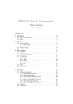
Contents
1. Agilent Technologies 11713A
Attenuator/Switch Driver
Overview . . . . . . . . . . . . . . . . . . . . . . . . . . . . . . . . . . . . . . . . . . . . . . . . . . . . . . . . . . . . . . . . . . .1-2
Compatible Attenuators and Switches . . . . . . . . . . . . . . . . . . . . . . . . . . . . . . . . . . . . . . . . .1-3
2. Installing the Agilent Technologies 11713A Attenuator/Switch Driver
Initial Inspection . . . . . . . . . . . . . . . . . . . . . . . . . . . . . . . . . . . . . . . . . . . . . . . . . . . . . . . . . . . .2-2
Environmental Limitations . . . . . . . . . . . . . . . . . . . . . . . . . . . . . . . . . . . . . . . . . . . . . . . . . .2-2
Preparing for use. . . . . . . . . . . . . . . . . . . . . . . . . . . . . . . . . . . . . . . . . . . . . . . . . . . . . . . . . . .2-2
Verifying Requirements . . . . . . . . . . . . . . . . . . . . . . . . . . . . . . . . . . . . . . . . . . . . . . . . . . . . .2-3
Figure 2-1 Line Voltage Selection . . . . . . . . . . . . . . . . . . . . . . . . . . . . . . . . . . . . . . . . . . . . .2-4
GPIB Addressing. . . . . . . . . . . . . . . . . . . . . . . . . . . . . . . . . . . . . . . . . . . . . . . . . . . . . . . . . . .2-5
Figure 2-2 GPIB Address Selection . . . . . . . . . . . . . . . . . . . . . . . . . . . . . . . . . . . . . . . . . . . .2-5
Table 2-1 ASCII Address Codes to Decimal Equivalents . . . . . . . . . . . . . . . . . . . . . . . . . . .2-5
Mating Connectors . . . . . . . . . . . . . . . . . . . . . . . . . . . . . . . . . . . . . . . . . . . . . . . . . . . . . . . . .2-6
Figure 2-3 General Purpose Interface Bus Connection . . . . . . . . . . . . . . . . . . . . . . . . . . . .2-6
Connecting to Attenuators and Switches . . . . . . . . . . . . . . . . . . . . . . . . . . . . . . . . . . . . . . .2-7
Table 2-2 Attenuator Cable Connector Pin Numbers and Wire Color Codes . . . . . . . . . . .2-8
Driving Additional Coaxial Switches . . . . . . . . . . . . . . . . . . . . . . . . . . . . . . . . . . . . . . . . . . .2-9
Figure 2-4 Connections for Coaxial Switches . . . . . . . . . . . . . . . . . . . . . . . . . . . . . . . . . . . .2-9
Figure 2-5 Connections for Agilent 8761B SPDT Switches . . . . . . . . . . . . . . . . . . . . . . . .2-10
Connecting to Four-Section . . . . . . . . . . . . . . . . . . . . . . . . . . . . . . . . . . . . . . . . . . . . . . . . .2-11
Figure 2-6 Typical Connections for Programmable Four-Section Attenuator . . . . . . . . . .2-11
Connecting to Relays. . . . . . . . . . . . . . . . . . . . . . . . . . . . . . . . . . . . . . . . . . . . . . . . . . . . . . .2-12
Figure 2-7 Relay Driving Circuit . . . . . . . . . . . . . . . . . . . . . . . . . . . . . . . . . . . . . . . . . . . . .2-12
Verifying Performance . . . . . . . . . . . . . . . . . . . . . . . . . . . . . . . . . . . . . . . . . . . . . . . . . . . . .2-12
3. Specifications
Specifications . . . . . . . . . . . . . . . . . . . . . . . . . . . . . . . . . . . . . . . . . . . . . . . . . . . . . . . . . . . . . . .3-2
Table 3-1 Specifications . . . . . . . . . . . . . . . . . . . . . . . . . . . . . . . . . . . . . . . . . . . . . . . . . . . . .3-2
Supplemental Characteristics . . . . . . . . . . . . . . . . . . . . . . . . . . . . . . . . . . . . . . . . . . . . . . . .3-2
Table 3-2 Supplemental Characteristics . . . . . . . . . . . . . . . . . . . . . . . . . . . . . . . . . . . . . . . .3-2
4. Verification
Recommended Test Equipment . . . . . . . . . . . . . . . . . . . . . . . . . . . . . . . . . . . . . . . . . . . . . . . . .4-2
Table 4-1 Recommended Test Equipment . . . . . . . . . . . . . . . . . . . . . . . . . . . . . . . . . . . . . . .4-2
Operator’s Check for Local Operation. . . . . . . . . . . . . . . . . . . . . . . . . . . . . . . . . . . . . . . . . . . .4-3
Figure 4-1 Local Operation Test Setup . . . . . . . . . . . . . . . . . . . . . . . . . . . . . . . . . . . . . . . . .4-3
GPIB Interface Check for Remote Operation . . . . . . . . . . . . . . . . . . . . . . . . . . . . . . . . . . . . . .4-5
Figure 4-2 GPIB Interface Check Test Setup . . . . . . . . . . . . . . . . . . . . . . . . . . . . . . . . . . . .4-5
Remote Message . . . . . . . . . . . . . . . . . . . . . . . . . . . . . . . . . . . . . . . . . . . . . . . . . . . . . . . . . . .4-6
Receiving the Message . . . . . . . . . . . . . . . . . . . . . . . . . . . . . . . . . . . . . . . . . . . . . . . . . . . . . .4-6
5. Local Operation
Local Control . . . . . . . . . . . . . . . . . . . . . . . . . . . . . . . . . . . . . . . . . . . . . . . . . . . . . . . . . . . . . . .5-2
Figure 5-l Front Panel Features . . . . . . . . . . . . . . . . . . . . . . . . . . . . . . . . . . . . . . . . . . . . . . .5-3
Figure 5-2 Rear Panel Features . . . . . . . . . . . . . . . . . . . . . . . . . . . . . . . . . . . . . . . . . . . . . . .5-4
1
Contents
6. Remote Operation
GPIB Compatibility . . . . . . . . . . . . . . . . . . . . . . . . . . . . . . . . . . . . . . . . . . . . . . . . . . . . . . . . . . 6-2
Remote Mode . . . . . . . . . . . . . . . . . . . . . . . . . . . . . . . . . . . . . . . . . . . . . . . . . . . . . . . . . . . . . 6-2
Local Mode . . . . . . . . . . . . . . . . . . . . . . . . . . . . . . . . . . . . . . . . . . . . . . . . . . . . . . . . . . . . . . . 6-2
Addressing . . . . . . . . . . . . . . . . . . . . . . . . . . . . . . . . . . . . . . . . . . . . . . . . . . . . . . . . . . . . . . . 6-3
Data Messages . . . . . . . . . . . . . . . . . . . . . . . . . . . . . . . . . . . . . . . . . . . . . . . . . . . . . . . . . . . . 6-3
Receiving the Data Message . . . . . . . . . . . . . . . . . . . . . . . . . . . . . . . . . . . . . . . . . . . . . . . . . 6-3
Sending the Data Message . . . . . . . . . . . . . . . . . . . . . . . . . . . . . . . . . . . . . . . . . . . . . . . . . . 6-4
Receiving the Trigger Message . . . . . . . . . . . . . . . . . . . . . . . . . . . . . . . . . . . . . . . . . . . . . . . 6-4
Receiving the Clear Message . . . . . . . . . . . . . . . . . . . . . . . . . . . . . . . . . . . . . . . . . . . . . . . . . 6-4
Receiving the Local Lockout Message . . . . . . . . . . . . . . . . . . . . . . . . . . . . . . . . . . . . . . . . . . 6-5
Receiving the Clear Lockout/Set Local Message . . . . . . . . . . . . . . . . . . . . . . . . . . . . . . . . . 6-5
Receiving the Pass Control Message . . . . . . . . . . . . . . . . . . . . . . . . . . . . . . . . . . . . . . . . . . . 6-5
Sending the Require Service Message . . . . . . . . . . . . . . . . . . . . . . . . . . . . . . . . . . . . . . . . . 6-5
Sending the Status Byte Message . . . . . . . . . . . . . . . . . . . . . . . . . . . . . . . . . . . . . . . . . . . . . 6-5
Sending the Status Bit Message . . . . . . . . . . . . . . . . . . . . . . . . . . . . . . . . . . . . . . . . . . . . . . 6-5
Table 6-1 GPIB Message Reference Table. . . . . . . . . . . . . . . . . . . . . . . . . . . . . . . . . . . . . . . 6-6
Table 6-2 GPIB Control Statement Results . . . . . . . . . . . . . . . . . . . . . . . . . . . . . . . . . . . . . 6-7
Table 6-3 Attenuation Levels and Corresponding Data Strings . . . . . . . . . . . . . . . . . . . . . 6-8
7. Replacing Major Assemblies
Replaceable Parts . . . . . . . . . . . . . . . . . . . . . . . . . . . . . . . . . . . . . . . . . . . . . . . . . . . . . . . . . . . 7-2
Table 7-1 Accessories Supplied . . . . . . . . . . . . . . . . . . . . . . . . . . . . . . . . . . . . . . . . . . . . . . . 7-2
Table 7-2 Line Fuse Part Numbers . . . . . . . . . . . . . . . . . . . . . . . . . . . . . . . . . . . . . . . . . . . . 7-2
Table 7-3 Major Assemblies . . . . . . . . . . . . . . . . . . . . . . . . . . . . . . . . . . . . . . . . . . . . . . . . . . 7-3
Table 7-4 Major Cables. . . . . . . . . . . . . . . . . . . . . . . . . . . . . . . . . . . . . . . . . . . . . . . . . . . . . . 7-3
Table 7-5 Cabinet Parts . . . . . . . . . . . . . . . . . . . . . . . . . . . . . . . . . . . . . . . . . . . . . . . . . . . . . 7-4
Module Cover Removal/Replacement . . . . . . . . . . . . . . . . . . . . . . . . . . . . . . . . . . . . . . . . . . . . 7-5
Front Panel Removal/Replacement . . . . . . . . . . . . . . . . . . . . . . . . . . . . . . . . . . . . . . . . . . . . . 7-6
Rear Panel Removal/Replacement . . . . . . . . . . . . . . . . . . . . . . . . . . . . . . . . . . . . . . . . . . . . . . 7-7
A1 Interconnect and Power Supply Assembly Removal/Replacement . . . . . . . . . . . . . . . . . . 7-8
A2 Driver Assembly Removal/Replacement. . . . . . . . . . . . . . . . . . . . . . . . . . . . . . . . . . . . . . . 7-9
A3 Latch Assembly Removal/Replacement . . . . . . . . . . . . . . . . . . . . . . . . . . . . . . . . . . . . . . 7-10
A4 Remote Local Logic Assembly Removal/Replacement . . . . . . . . . . . . . . . . . . . . . . . . . . . 7-11
A5 GPIB Handshake Data Input Assembly Removal/Replacement. . . . . . . . . . . . . . . . . . . 7-12
A6 Interface Assembly Removal/Replacement . . . . . . . . . . . . . . . . . . . . . . . . . . . . . . . . . . . 7-13
A7 Switch Board Assembly Removal/Replacement . . . . . . . . . . . . . . . . . . . . . . . . . . . . . . . . 7-14
A8 Power Supply/Line Filter Assembly Removal/Replacement . . . . . . . . . . . . . . . . . . . . . . 7-15
8. Servicing the Attenuator/Switch Driver
Preparing a Static-Safe Workstation . . . . . . . . . . . . . . . . . . . . . . . . . . . . . . . . . . . . . . . . . . . . 8-2
Figure 8-1 Static-Safe Work Station . . . . . . . . . . . . . . . . . . . . . . . . . . . . . . . . . . . . . . . . . . . 8-2
Reducing ESD Damage . . . . . . . . . . . . . . . . . . . . . . . . . . . . . . . . . . . . . . . . . . . . . . . . . . . . . 8-2
Table 8-1 Static-Safe ESD Accessories . . . . . . . . . . . . . . . . . . . . . . . . . . . . . . . . . . . . . . . . . 8-3
Maintenance and Adjustments . . . . . . . . . . . . . . . . . . . . . . . . . . . . . . . . . . . . . . . . . . . . . . . . . 8-4
Fuse Removal/Replacement. . . . . . . . . . . . . . . . . . . . . . . . . . . . . . . . . . . . . . . . . . . . . . . . . . 8-4
Adjustments . . . . . . . . . . . . . . . . . . . . . . . . . . . . . . . . . . . . . . . . . . . . . . . . . . . . . . . . . . . . . . 8-4
Troubleshooting . . . . . . . . . . . . . . . . . . . . . . . . . . . . . . . . . . . . . . . . . . . . . . . . . . . . . . . . . . . . . 8-5
2
Contents
Isolating a Malfunction. . . . . . . . . . . . . . . . . . . . . . . . . . . . . . . . . . . . . . . . . . . . . . . . . . . . . .8-5
Parts Identification . . . . . . . . . . . . . . . . . . . . . . . . . . . . . . . . . . . . . . . . . . . . . . . . . . . . . . . . .8-7
Figure 8-2 11713A Attenuator/Switch Driver Top Cover Removed . . . . . . . . . . . . . . . . . . .8-8
Figure 8-3 11713A Attenuator Switch Driver Bottom Cover Removed . . . . . . . . . . . . . . . .8-9
11713A Simplified Block Diagram . . . . . . . . . . . . . . . . . . . . . . . . . . . . . . . . . . . . . . . . . . . . .8-11
Troubleshooting the A1 Interconnect Assembly. . . . . . . . . . . . . . . . . . . . . . . . . . . . . . . . . . .8-13
Troubleshooting the A2 Driver Assembly . . . . . . . . . . . . . . . . . . . . . . . . . . . . . . . . . . . . . . . .8-14
Troubleshooting the A3 Latch Assembly . . . . . . . . . . . . . . . . . . . . . . . . . . . . . . . . . . . . . . . .8-16
Troubleshooting the A4 Local Logic Assembly . . . . . . . . . . . . . . . . . . . . . . . . . . . . . . . . . . . .8-17
Troubleshooting the A5 Handshake and Data Input Assembly . . . . . . . . . . . . . . . . . . . . . .8-18
Troubleshooting the A6 Interface Assembly. . . . . . . . . . . . . . . . . . . . . . . . . . . . . . . . . . . . . .8-20
Troubleshooting the A7 Switch Board Assembly . . . . . . . . . . . . . . . . . . . . . . . . . . . . . . . . . .8-21
The A8 power supply/line module assembly . . . . . . . . . . . . . . . . . . . . . . . . . . . . . . . . . . . . . .8-23
3
1
Agilent Technologies 11713A
Attenuator/Switch Driver
Overview
In this chapter you will find:
• Function, features, and capabilities of the 11713A attenuator/switch
driver
• Compatible Agilent Technologies switches and attenuators
Agilent Technologies 11713A Attenuator/Switch Driver
Overview
Overview
The 11713A attenuator/switch driver is an GPIB compatible
instrument designed to provide control of up to two four-section
programmable step attenuators and two microwave coaxial switches.
Features
• Instrument control is accomplished manually from front panel
pushbuttons or automatically over the GPIB interface bus.
• Programing via the GPIB can be accomplished in simple one line
statements.
• The attenuator/switch driver features front panel status monitoring
and a self-contained power supply with current limiting.
• The instrument includes solenoid arc suppression diodes and has
common terminal supplies of +24 Vdc.
• Connections are made at the rear panel to the ten pairs of current
sinking transistors
❍ Five
contact pairs per set are present at each rear panel
multi-pin plug. This plug mates with the attenuator drive cable.
Options
❍
The remaining two contact pairs are connected to the banana
jacks mounted on the rear panel. The banana jacks are
available for driving the coaxial switches or for optional
applications.
❍
Each pair of contacts is individually programmable via GPIB or
from the front panel pushbutton.
❍
The contact pair status is indicated by the front panel LEDs in
the appropriate pushbutton
❍
The contact pairs 9 and 0 can be used to switch between one of
two loads or to reverse the current through a single load.
The Option 907 front handle kit contains front panel handles that can
be added to the driver cabinet.
The Option 908 rack adapter kit contains the flange and hardware for
mounting the driver in a standard rack of 48.3 cm (19 inches).
1-2 11713A Operating and Service Manual
Agilent Technologies 11713A Attenuator/Switch Driver
Overview
Compatible Attenuators and Switches
The 11713A attenuator/switch driver is designed to drive the following
Agilent Technologies attenuators and switches. If you are using
attenuators and switches made by another company, check their
switching characteristics against those specified in Chapter 3,
"Specifications".
Table 1-1 Compatible Agilent Technologies Switches
Agilent Model Number
Description
8761B
SPDT
8762,B,C,F (3331A,B,C)
Terminated SPDT
8763A,B,C (33312A,B,C)
1-port Terminated SP3T
8764A,B,C (33313A,B,C)
Unterminated SP4T
8765A,B,C,D,F Opt 024 and 100(33314A,B,D)
Unterminated SPDT
8766K (33366K)
Unterminated SP3T
8767K (33367K)
Unterminated SP4T
8768K (33368K)
Unterminated SP5T
8769K (33369K)
Unterminated SP6T
87104A,B, C Option 100
Terminated SP4T
87106A,B,C Option 100
Terminated SP6T
87204A,B,C Option 100
Terminated SP4T
87206A,B,C Option 100
Terminated SP6T
87222C,D,E Option 100a
2P2T Transfer
87406B Option 100
4-port Matrix
87606B Option 1006
6-port Matrix
a. See caution on page 2-7.
Table 1-2 Compatible Agilent Technologies Attenuators
Agilent Model Number
Description
8494G,H (33320G,H)
11 dB, 1 dB steps
8495G,H,K (33321 G,H,K)
70 dB, 10 dB steps
8496G,H (33322G,H)
110 dB, 10 dB steps
8497K ( 33323K)
90 dB, 10 dB steps
84904K,L (33324K,L)
11 dB, 1 dB steps
84906K,L ( 33326K,L
90 dB, 10 dB steps
84907K,L (33327K,L)
70 dB, 10 dB steps
11713A Operating and Service Manual 1-3
Agilent Technologies 11713A Attenuator/Switch Driver
Overview
Connecting Accessories
Table 1-3 lists accessories that are available for the 11713A
attenuator/switch driver. Supplied accessories include two dual Viking
connector cables, 12-pin conductor, 60 inches long, and a line power
cable. Refer to "Replaceable Parts".
Table 1-3 Available Accessories
Accessories Available But Not Supplied
Interconnect kit (Type-N connectors)a
Agilent 11716A
Interconnect kit (7-mm connectors)a
Agilent 11716B
Interconnect kit (SMA connectors)a
Agilent 11716C
Attenuator/switch driver rear cord wrap kitb
Agilent 5062-3995
Viking connector to four ribbon cables to connect up to
four switches
Agilent 11761A
Viking connector to 10-pin DIP connector, 60 inches long
Agilent 11764B
9-Pin conductor cable, to Viking connector (for five
switches), 60 inches long.
8120-2178
12-Pin conductor cable, bare wire to Viking connector
(for five switches, 60 inches long.
5061-0969
a. Order this kit to connect two programmable step attenuators in series.
b. Order this kit to set the driver on the rear panel for bench operation.
Recommended Test Equipment
Recommended test equipment for verifying performance and for
troubleshooting the 11713A attenuator/switch driver is given in Table
4-1.
1-4 11713A Operating and Service Manual
2
Installing the Agilent
Technologies 11713A
Attenuator/Switch Driver
Overview
In this chapter you will learn about:
• How to unpack and check your instrument
• How to contact Agilent Technologies for service
• Operating requirements for the attenuator/switch driver
• How to set the GPIB address of your instrument
• How to connect to switches, attenuators, and relays
Installing the Agilent Technologies 11713A Attenuator/Switch Driver
Initial Inspection
1. Unpack and inspect the shipping container and its contents
thoroughly to ensure that nothing was damaged during shipment. If
the shipping container or cushioning material is damaged, the
contents should be checked both mechanically and electrically.
2. If the contents are damaged or defective, contact your nearest
Agilent Technologies Service and Support Office. Refer to the Service
and Support information in the front matter of this manual. Agilent
Technologies will arrange for repair or replacement of the damaged
or defective equipment. Keep the shipping materials for the carrier’s
inspection.
3. If you are returning your instrument for service, repackaging the
attenuator/switch driver requires original shipping containers and
materials or their equivalents. Agilent Technologies can provide
packaging materials identical to the original materials. Refer to
"Service and Support" on page v for the Agilent Technologies nearest
you.
Environmental Limitations
4. Ensure that you meet the environmental limitations for storage and
shipment:
Temperature
-55 to 75 °C
Humidity
< 90% relative
Altitude
< 15,300 meters (50,000 feet)
Preparing for use
Bench Operation
5. For bench operation, supplied equipment includes:
plastic feet shaped to assure self-alignment of the instruments
when stacked
❍
fold-away tilt stands to raise the front of the instrument for easier
viewing of the control panel
❍
If the driver is to be used in a position that requires setting it on the
rear panel, a kit is available (refer to Table 1-3) that includes feet with
mounting screws.
Rack Mounting
6. For rack mounting the instrument, use the rack-adapter kit
half-module. (Refer to Table 1-3).
To install the kit:
❍
Remove the feet and tilt stands.
❍
Remove the side trim strips.
❍
Attach the rack mount flange and flange adapter.
2-2 11713A Operating and Service Manual
Installing the Agilent Technologies 11713A Attenuator/Switch Driver
Verifying Requirements
7. Verify that you meet the following requirements.
❏ Power source
❍
100 to 120 volts (+5%, –10%) from 48 to 440 Hz
❍
220 to 240 volts (+5%, –10%) from 48 to 66 Hz, single phase.
❏ Power consumption
❍
80 VA max
CAUTION
Before the instrument is switched on, it must be set to the voltage of the
power source or damage to the instrument may result. Refer to Figure
2-1.
WARNING
If this instrument is to be energized via an autotransformer for
voltage reduction, make sure the common terminal is
connected to the earthed pole power source.
❏ Power Cable
In accordance with international safety standards, a three-wire
power cable is provided with this instrument. When it is
connected to an appropriate ac power receptacle, the cable
grounds the instrument cabinet. The type of power cable plug
shipped with each instrument depends on the country of origin.
11713A Operating and Service Manual 2-3
Installing the Agilent Technologies 11713A Attenuator/Switch Driver
Figure 2-1 Line Voltage Selection
WARNING
To avoid the possibility of hazardous electrical shock, do not
operate this Instrument at line voltages greater than 126.5 Vac
with line frequencies greater than 66 Hz (leakage currents at
these line settings may exceed 3.5 mA).
❏ Line Voltage and Fuse Selection
a. Open the cover door of the line power module. Push the fuse-pull
lever to the left and remove the fuse. (Refer to Figure 2-1.)
b. Pull out the voltage selector PC board. Position the board so that the
voltage nearest the actual fine voltage level is on the top-left side of
the board.
c. Push the board firmly into the module slot.
d. Push the fuse-pull back into normal right-hand position.
e. Check that the fuse is the correct rating and type for the input ac
line voltage. Fuse ratings for line voltages are indicated below the
power module.
f. Insert the fuse into the holder.
2-4 11713A Operating and Service Manual
Installing the Agilent Technologies 11713A Attenuator/Switch Driver
GPIB Addressing
8. Use the five-bit address switches located on the rear panel of the
instrument to change the GPIB address.
❍ The
11713A has a factory preset address of decimal 28. The
switch labeled with a one is the least significant bit.
❍ There
are 32 possible addresses. Addresses 0 and 31 are
typically reserved for GPIB functions and should not be used.
IEE-488.1 limits the number of addressable elements
(instruments) to 16.
Figure 2-2 GPIB Address Selection
GPIB Address
Table 2-1 ASCII Address Codes to Decimal Equivalents
ASCII Address
Codes - LISTEN
Decimal
Equivalents
ASCII Address
Codes - LISTEN
Decimal
Equivalents
SP
00
0
16
!
01
1
17
“
02
2
18
#
03
3
19
$
04
4
20
%
05
5
21
&
06
6
22
‘
07
7
23
(
08
8
24
)
09
9
25
*
10
:
26
+
11
;
27
,
12
<
28
-
13
=
29
.
14
>
30
/
15
?
31
11713A Operating and Service Manual 2-5
Installing the Agilent Technologies 11713A Attenuator/Switch Driver
Mating Connectors
❏ Mating connectors used with the driver are the 24-pin GPIB male,
the 12-pin Viking Industries connector, and the banana type male.
Figure 2-3 provides interconnection data for the General Purpose
Interface Bus.
Figure 2-3 General Purpose Interface Bus Connection
Logic levels
The interface bus logic levels are TTL compatible, that is, the true (1)
state is 0.0 to +0.4 Vdc and the false (0) state is +2.5 to +5.0 Vdc.
Programming
and Output data
format
Refer to Chapter 6, "Remote Operation".
Mating connector Agilent 1251-0293
Mating cables
available1
Agilent 10833A, 1 meter (3.3 ft.), Agilent 10833B, 2 meters (6.6 ft.)
Agilent 10833C, 4 meters (13.2 ft.), Agilent 10833D, 0.5 meter (1.6 ft.)
CAUTION
The maximum accumulative length of connecting cable for an interface
bus system is 20 meters (65.5 ft.)
A general purpose interface bus system may contain no more than 2
meter (6.6 ft.) of connecting cable per instrument.
1. The Agilent 10834A adapter is required with these cables to provide additional clearance for the
cable connections.
2-6 11713A Operating and Service Manual
Installing the Agilent Technologies 11713A Attenuator/Switch Driver
Connecting to Attenuators and Switches
❏ Use the two plug-in drive cables supplied with the driver to connect
to Attenuators and the multi-pin plugs on the rear panel.
These attenuator cables have 12-pin connectors that may not be usable
on some equipment. In these instances, the cable may be modified by
removing a connector. A 9-wire cable with only one connector is also
available. (Refer to Table 1-3.)
Table 2-2 describes the cable wire colors/connector pin numbers and
corresponding status of the front panel pushbutton indicators.
To drive a simple non-latching relay, only one wire in a pair needs to be
used for the ground. Refer to Figure 2-7 for a typical relay-driving
schematic.
CAUTION
Do not drive the 87222C/D/E using the S9 or S0 outputs from either the
banana plug outputs, or from pins 3 or 4 within the Atten X and
Atten Y Viking sockets, both located on the rear panel of the 11713A.
11713A Operating and Service Manual 2-7
Installing the Agilent Technologies 11713A Attenuator/Switch Driver
Table 2-2 Attenuator Cable Connector Pin Numbers and Wire
Color Codes
Front Panel Pushbuttons a
ATTENUATOR X, Y, and SWITCHES
Pushbutton
Number
SWITCHE
S
9
9
0
0
ATTENUATORS
X
Y
1
5
2
6
3
7
4
8
Pushbutton LEDs
Rear Panel connectors ATTEN X or Y, and
Attenuator Cable
Pin Numbers
Attenuator Cable Wire
Color Code
Red (24 Vdc)
White/Brown (Gnd)
ON
OFF
ON
OFF
1
2
Connect to S9 and
S0 outputs
ATTEN X 3(S9-A)
ATTEN X 4(S9-B0
ATTEN Y 3 (S0-A)
ATTEN Y 4 (S0-B)
OFF
ON
OFF
ON
OFF
ON
OFF
ON
5
6
7
8
9
10
11
12
Violet
Yellow
Black
Green
Orange
Blue
Brown
White
Gray
White/Red
Grey
White/Red
a. The ON/OFF status of the pushbutton lamps indicates which cable wire or pin on the
rear panel connector is grounded.For example, if ATTENUATOR X pushbutton 3 is illuminated, pin 10 of the ATTEN X connector (blue wire of the cable) is grounded and pin 9
floats at a high impedance.
For the SWITCHES, if pin 3 is grounded (lamp on), pin 4 is connected to +24 V.
2-8 11713A Operating and Service Manual
Installing the Agilent Technologies 11713A Attenuator/Switch Driver
Driving Additional Coaxial Switches
❏ Make switch connections to S0 outputs, S9 outputs, or to rear panel
ATTEN X output or ATTEN Y output.
Figure 2-4 shows the rear panel connections to S0 outputs and the
GPIB command necessary to change the position of Agilent 8762 or
8765 series coaxial switches. (For GPIB command usage, refer to
"Data Message Input Format")
Connections to Agilent 8762 or 8765 series coaxial switches can also
be made to the ATTEN X output or ATTEN Y output (refer to Figure
2-6 for connections/pin numbers). Control can be extended to four,
eight, or 10 switches if S0 and S9 outputs are also used.
Figure 2-4 Connections for Coaxial Switches
❏ GPIB command "B0" connects port C and port 1 and turns the front
panel LED for pushbutton 0 OFF.
❏ GPIB command "A0" connects port C and port 2 and turns the front
panel LED for pushbutton 0 ON.
11713A Operating and Service Manual 2-9
Installing the Agilent Technologies 11713A Attenuator/Switch Driver
Figure 2-5 shows the rear panel connections and the GPIB command
necessary to change the position of Agilent 8761B SPDT RF switches.
(For GPIB command usage, refer to "Data Message Input Format" on
page 6-3.)
Figure 2-5 Connections for Agilent 8761B SPDT Switches
❏ GPIB command "B9" connects port C and port 2 and turns the front
panel LED for pushbutton 9 OFF.
❏ GPIB command “A9” connects port C and port 1 and turns the front
panel LED for pushbutton 9 ON.
2-10 11713A Operating and Service Manual
Installing the Agilent Technologies 11713A Attenuator/Switch Driver
Connecting to Four-Section
❏ To use one four-section attenuator assembly, connect an attenuator
cable to either the ATTEN X output (A6J1) or ATTEN Y output
(A6J2). Connect both outputs to have more than four attenuator
segments.
Figure 2-6 shows a typical connection for a programmable
four-section attenuator and illustrates the connection/pin number
for each connector: ATTEN X or ATTEN Y Using these same
connections to Agilent 8762 or 8765 series coaxial switches, control
can be extended to four, eight, or ten switches if S0 and S9 outputs
are also used.
Figure 2-6 Typical Connections for Programmable Four-Section
Attenuator
11713A Operating and Service Manual 2-11
Installing the Agilent Technologies 11713A Attenuator/Switch Driver
Connecting to Relays
❏ To drive ten devices, connect attenuator cables at ATTEN X and Y
and switch cables to S9 and S0.
A total of 10 relays may be on at one time if the total current is less
than 650 mA. However, since there are dual transistor and relay
drivers, where one driver is on while the other is off, a total of 20
relays may be controlled.
Figure 2-7 shows the connections for a simplified relay driving
circuit. This circuit is adaptable for simple non-latching relays.
CAUTION
If the total continuous load current of 650 mA is exceeded, damage may
result.
Figure 2-7 Relay Driving Circuit
NOTE
It is also recommended that two 28.7 V zener diodes be connected
back-to-back across the relay coils to reduce voltage transients.
Verifying Performance
9. Use the procedure for checking the electrical performance of the
attenuator/switch driver given in Chapter 4. If there is mechanical
damage or a defect, or if the instrument does not pass the electrical
performance test, notify the nearest Agilent Technologies office.
WARNING
To avoid hazardous electrical shock, do not perform electrical
tests when there are signs of shipping damage to any portions
of the outer enclosure (covers, panels, connectors).
2-12 11713A Operating and Service Manual
3
Specifications
Overview
In this chapter you will find:
• Specifications which describe warranted performance standards
• Supplemental characteristics which are non-warranted parameters
Specifications
Specifications
Specifications describe warranted performance over the temperature
range 0 to +55 °C after one hour of continuous operation, unless
otherwise noted.
Table 3-1 Specifications
Drive Power Supply
Voltage
+ 24 ± 2.0 Vdc
Current
1.3 A maximum peak for 1 second
0.65 A maximum continuous current
Contact pairs 1 through 8, 9, and 0, maximum
current of 0.65 A continuous through one or all
contacts
Supplemental Characteristics
Supplemental characteristics are intended to provide useful
information. They are typical but non-warranted performance
parameters.
Table 3-2 Supplemental Characteristics
Power
100 or 120 Vac, +5%, –10% at 48 to 440 Hz
200 or 240 Vac, +5%, –10% at 48 to 66 Hz
80 VA maximum
Response Time
10 µs maximum for contact pairs 1 through 8
20 µs maximum for contact pairs 9 and 0
Driver Life
> 2,000,000 switchings at maximum current for
contact pairs 9 and 0
Maximum Load Inductance
500 mH
Maximum Load Capacitance
< 0,01 µF for contact pairs 9 and 0
Net Weight
4.1 kg (9 lbs)
Dimensions
Height: 102 mm (4 inches including feet)
Rack height: 89 mm (3.5 inches, half-width
module)
Width: 213 mm (8.4 inches)
Depth: 295 mm (11.6 inches)
3-2 11713A Operating and Service Manual
4
Verification
Overview
In this chapter you will find:
• Recommended test equipment
• How to verify local operation
• How to verify GPIB interface remote operation
Verification
Recommended Test Equipment
Recommended Test Equipment
Recommended Test Table 4-1 lists the test equipment required for
performance verification and Equipment troubleshooting. Equipment
other than the recommended models can be used provided the
minimum specifications are satisfied.
Table 4-1 Recommended Test Equipment
Instrument Type
Critical Specifications
Usea
Digital voltmeter
0 to + 30 Vdc
T
Attenuators (2 required)
Programmable, 4 sections
P, T
Switches (2 required)
+ 24 Vdc drive source
P, T
Controller GPIB
GPIB compatible
P, T
a. P = Performance; T = Troubleshooting
4-2 11713A Operating and Service Manual
Verification
Operator’s Check for Local Operation
Operator’s Check for Local Operation
This check tests initial driver turn-on and local operation.
Check that the following initial conditions are met before you proceed.
❏ Verify that driver power transformer primary is matched to the line
voltage by the Line Voltage Selection Card.
❏ Check the driver power fuse for correct rating. Current fuse ratings
for various line voltages are given on the line power module on rear
panel.
❏ Connect the power cable to the power receptacle.
Procedure
1. Connect the equipment that is to be used in your application as
shown below.
Figure 4-1 Local Operation Test Setup
11713A Operating and Service Manual 4-3
Verification
Operator’s Check for Local Operation
2. Press the LINE ON/OFF switch to ON. Switch should remain in the
ON position and the green switch indicator LED should illuminate.
All numbered pushbutton LEDs should be on and LOCAL LED
should be on.
3. Depress the 10 numbered pushbuttons on the driver front panel.
Each LED should alternate between off and on as each key is
pressed.
In addition, if any equipment is connected (attenuators, relays, or
switches), an audible click should be heard from the unit actuated.
Pressing any numbered pushbutton should not cause any other
pushbutton to change state.
4-4 11713A Operating and Service Manual
Verification
GPIB Interface Check for Remote Operation
GPIB Interface Check for Remote Operation
These procedures check the driver’s ability to process the GPIB
messages described in the GPIB Message Reference Table 4-1. The
checks can be performed together or separately.
The validity of these checks are based on the following assumptions:
• The driver operates correctly with front panel control (that is, in
local mode). This can be verified with the Local Operation check.
• The controller properly executes GPIB operation.
• The GPIB interface properly executes the controller's instructions.
If the driver appears to fail any of the GPIB checks, the validity of the
above assumptions should be confirmed before servicing the driver.
If all of these checks are successful, the driver's GPIB interface is
operating correctly. These procedures do not check all of the driver's
program codes that can be executed. However, if the driver works
correctly from the front panel, and the GPIB interface works correctly,
there is a high probability that the driver will respond to all the
program codes.
Initial Setup
Connect the driver to the controller with the GPIB cable as shown in
the test setup below. The cable must remain connected for all tests.
Figure 4-2 GPIB Interface Check Test Setup
11713A Operating and Service Manual 4-5
Verification
GPIB Interface Check for Remote Operation
The select code of the controller’s I/O is assumed to be 7. The address of
the driver is assumed to be 28 (factory preset). This select code-address
combination (728) is not necessary for these checks to be valid. If
necessary, modify the program lines presented here with the
appropriate combination for your instrument.
Remote Message
This check assumes that the driver is in the local state. If the driver is
in the remote state (front panel REMOTE light ON), switch the driver
off and then on again.
Description
Command
Send remote message to the driver
REMOTE 728
Operator’s Response
Check that the driver’s REMOTE light turns ON. If it does not, the
driver failed to process the remote message.
Receiving the Message
This check determines if the driver receives data messages. The driver
must be in the remote state. Check that all front panel LEDs are ON
except local when the driver first comes on and is set to the remote
state.
Description
Command
Address the driver to listen and
send data messages
OUTPUT 728; "B1234567890"
OUTPUT 728; "A1234567890"
Operator’s Check
After the first data message is sent, check that the front-panel LEDs
are OFF. After the second data message is sent, check that the LEDs
are ON. If not, the driver failed to process the data message.
4-6 11713A Operating and Service Manual
Verification
GPIB Interface Check for Remote Operation
Local Lockout and Clear Lockout/ Set Local Messages
This check requires the bus to be in the remote state. Check that the
driver’s REMOTE light is ON.
Description
Command
Local Lockout: Send Local Lockout message.
LOCAL LOCKOUT 7
Operator’s Response
Press the LOCAL key on the driver front panel. The REMOTE LED
should remain ON. If not, the driver failed to process the Local Lockout
message.
Description
Command
Clear Lockout/Set Local:
LOCAL 7
Send Clear Lockout/Set Local message to clear
Local Lockout messages and set all devices to
Local
Operator’s Response
Check that the LOCAL light is ON and REMOTE light is OFF. Press
numbered pushbutton switches and check that switches change status
(LEDs on and off). If not, the driver failed to process the Clear
Lockout/Set Local message.
11713A Operating and Service Manual 4-7
5
Local Operation
Overview
In this chapter you will find:
• Function and description of front panel controls, connectors, and
indicators
• Function and description of rear panel controls, connectors, and
indicators
Local Operation
Local Control
Local Control
Local control of the Agilent 11713A switch driver is accomplished
manually from front panel pushbuttons.
Figure 5-1 and Figure 5-2 detail front and rear panel controls,
connectors, and indicators.
5-2 11713A Operating and Service Manual
Local Operation
Local Control
Figure 5-l Front Panel Features
[1] ATTENUATOR X
[4] LOCAL
In the local mode, pushbutton switches 1,
2, 3, and 4 activate solid state switches
(current sinks) to change the attenuation
setting of an attenuator connected to the
ATTEN X connector on the rear panel.
Pushbutton switch that resets to
the local mode when not in local
lockout. LED turns on in LOCAL
mode.
[2] ATTENUATOR Y
In the local mode, pushbutton switches 5,
6, 7, and 8 activate solid state switches
(current sinks) to change the attenuation
setting of an attenuator connected to the
ATTEN Y connector on the rear panel.
[5] REMOTE LED
When on, the remote LED indicates
that the driver is in remote control.
[3] S9 A,B
In the local mode, Pushbutton switches 9
and 0 change the position of a coaxial
switch connected to rear panel banana
jacks S9 A, B and S0 A, B respective y.
[6] LINE ON LED When on, this
LED indicates that power is
applied to the attenuator/switch
drives.
[7] LINE OFF/ON
The line off/on button controls
primary power
11713A Operating and Service Manual 5-3
Local Operation
Local Control
Figure 5-2 Rear Panel Features
[1] ATTEN X
[8] Fuse
Connector to accept cable plug going to
programmable attenuator X
1.25 A at 110/120 Vac; 750 mA at
220/240 Vac
[2] ATTEN Y
[9] Line Voltage Selection Card
Connector to accept cable plug going to
programmable attenuator Y
[3] S9 A,B
Matches transformer primary to line
voltage
[10] Receptacle
Banana jack connectors for hook up to the
coaxial switches
Matches transformer primary to line
voltage via power cable
[4] 24 Vdc
[11] Line Power Module Assembly
Banana jack connector provides the common
connection for the +24 Vdc used to drive the
coaxial switches.
[12]
[5] S0 A,B
Banana jack connectors for hook up to the coaxial
switches
This symbol is used to point out a
necessary reference for the user.
[6] Window
[13] GPIB Address
Safety interlock; fuse cannot be removed while
power cable is connected to power receptacle
Switches to set the address of the
driver (decimal 28 is factory preset)
[7] Fuse Pull Handle
[14] GPIB Connector
Mechanical interlock; fuse must be removed
before extraction of Line Voltage Selection Card
The interface connector from a
source device to a listening device for
the remote mode of operation
5-4 11713A Operating and Service Manual
Remote Operation
6
Remote Operation
Overview
In this chapter you will learn about:
• Remote programming capability of the attenuator/switch driver
• Function and use of GPIB commands in remote mode
• Programming information to set up desired level of attenuation
11713A Operating and Service Manual 6-1
Remote Operation
The driver can be operated remotely through the General Purpose
Interface Bus (GPIB).
GPIB Compatibility
Remote-only functions and all front panel functions (except the LINE
switch) are programmable through the GPIB. The operator’s interface
check in Chapter 4, "Verification" provides a test of the GPIB to verify
that the driver can function with each of the applicable bus messages.
Table 6-1 summarizes the driver’s GPIB capabilities in terms of the
twelve bus messages.
Remote Mode
The driver accepts commands from the bus in the remote mode. In
remote, its front panel controls are disabled (except for the LINE switch
and the LOCAL pushbutton). The LOCAL pushbutton can be disabled
by a local lockout command. The driver can be addressed to listen and
when addressed to listen, the driver will respond to the following
messages: Data, Remote, Local Lockout, and Clear Lockout/Set Local.
Local-to-Remote Changes
The driver switches to remote operation upon receipt of the Remote
message. The Remote message has two parts:
• Remote enable bus control line (REN) set true
• Device listen address (MLA) received once (while REN is true)
The driver's outputs and all control settings remain unchanged with
the Local-to-Remote transition. The REMOTE LED is ON when the
driver is in the remote state.
Local Mode
In local, the driver's front-panel controls are fully operational and the
instrument will respond to the Remote message. Whether addressed or
not, it will also respond to the Local Lockout and Clear Lockout/Set
Local messages.
Remote-to-Local Changes
The driver returns to local control upon receipt of the Clear Lockout/Set
Local message (REN). If the driver is not in Local Lockout, it switches
to local from remote when the front panel LOCAL key is pressed. With
the remote-to-local transition, the driver's outputs remain unchanged.
6-2 11713A Operating and Service Manual
Remote Operation
Local Lockout
The local lockout condition disables the front panel LOCAL key so that
pressing the LOCAL key will not return the driver to local mode. When
local lockout is in effect, the driver is returned to local under program
control.
(sending Clear Lockout/Set Local) or by turning the driver LINE switch
OFF and ON. However, returning to local by switching to OFF and then
ON, will defeat the purpose of local lockout and the system controller
will lose control.
Addressing
The driver’s listen address is set by the slide switches on the rear panel.
Refer to "GPIB Addressing".
Data Messages
The state of the driver is controlled by data message on the GPIB. Data
messages include the driver’s GPIB program codes. The GPIB program
codes contain information for programming the front panel functions
(except for the LINE switch). The driver receives data messages when
addressed to listen.
Receiving the Data Message
The driver responds to data messages when in remote and addressed to
listen.
Data Message Input Format
The programming data string for the driver consists of a string of ASCII
coded characters composed of one or both of the following fields:
[Adm] [Bdn]
where: A or a = general ON command; B or b = general OFF command
dm = any digits 0 through 9 (excluding dn)
dn = any digits 0 through 9 (excluding dm)
The driver responds to an alphanumeric data string such as "A12B34"
when the driver is in the remote state and addressed to listen. (The
alpha characters in the data string can be either upper or lower case).
11713A Operating and Service Manual 6-3
Remote Operation
The data string is further defined as follows:
Ax Bx Ay By A/B 9 A/B 0
where: Ax Bx = data string for ATTEN X
(x can be none, one or more of the digits 1, 2, 3, or 4)
Ay By = data string for ATTEN Y
(x can be none, one or more of the digits 5, 6, 7, or 8)
Note that if Ax (Ay) uses a digit, then that digit may not be used in Bx
(By).
A/B 9 = GPIB command for switch S9
A/B 0 = GPIB command for switch S0
The data string contains the operation selected by the user (desired
contact closure, value of attenuation, etc.). The coded command from
the controller is converted by the driver into control voltages. The
output control voltages drive the device and illuminate front panel
lights that indicate the operation selected.
❏ Table 6-2 shows the relationship between each programming code and the
effect it has on the output at each connector/pin.
❏ Table 6-3 shows the programming strings required to set up various three
and four-section attenuators to the desired levels of attenuation.
Program Execution Time
The response time for the driver is defined as the time between data
valid (DAV) changing from a high to a low and the output signal at the
rear panel connector changing state. The switching speed of the Agilent
Technologies programmable attenuators is 20 ms including 10 ms for
the driver (ATTEN outputs). The switching speed for the RF switches is
20 to 50 ms plus 20 ms for the driver (S9 and S0 outputs).
Sending the Data Message
The driver does not have the capability of sending a data message.
Receiving the Trigger Message
The driver does not respond to the Trigger message.
Receiving the Clear Message
The remote message causes the driver to switch to the remote mode.
The remote message has two parts: the remote enable (REN) and
address-to-listen. The driver’s outputs do not change with the
local-to-remote transition. The REMOTE LED turns on when the driver
is in remote mode.
6-4 11713A Operating and Service Manual
Remote Operation
Receiving the Local Message
The driver does not respond to the local message. When the driver is in
Local Message remote mode, it can be returned to local mode with a
Clear Lockout/Set Local message.
The front panel LOCAL key can also return the driver to local mode.
However, pressing the LOCAL key might interrupt a data message to
the driver. This would leave the driver in a state unknown to the
controller. This situation would be undesirable and is avoided by
setting the Local Lockout condition which disables the LOCAL key.
Receiving the Local Lockout Message
The LOCAL pushbutton switch is disabled with Local Lockout in effect.
The driver is returned to local through program control by the
controller.
NOTE
The driver may also be returned to local by turning the driver LINE
switch off and then on, but this defeats the purpose of the Local Lockout
and the system controller loses control.
Receiving the Clear Lockout/Set Local Message
The system controller sends a Clear Lockout/Set Local message to clear
the Local Lockout condition and return all devices to local. No
instrument settings are changed when going from local lockout (remote
control) to local control.
Receiving the Pass Control Message
The driver does not respond to the Pass Control message because it
cannot act as a controller
Sending the Require Service Message
The driver cannot send a Require Service message.
Sending the Status Byte Message
The driver does not respond to a serial poll and as a result does not send
the Status Bit message.
Sending the Status Bit Message
Table 6-1 summarizes the driver’s GPIB capabilities in terms of the
twelve bus messages.
11713A Operating and Service Manual 6-5
Remote Operation
Table 6-1 summarizes the driver’s GPIB capabilities in terms of the
twelve bus messages.
Table 6-1 GPIB Message Reference Table
GPIB
Message
Applicable
Response
Related
Commands
and
Controlsa
Interface
Functions
Data
yes
All front panel functions, except LINE
ON/OFF switch, are programmable. The
front panel REMOTE indicator turns on
when addressed.
Data
No
The driver does not respond to the
trigger message
GET
DT0
Trigger
No
The driver does not respond to the clear
message.
DCL, SDC
DC0
Clear
No
The driver does not respond to the clear
message
REN
RL1b
Remote
Yes
The driver remote mode is enabled when
the REN bus line is true. However, R
remains in local (i.e, the front panel is
active) until it is addressed to listen the
first time. The output signal is
unchanged. The front panel REMOTE
indicator turns on when in remote mode.
GTL
RL1b
Local
No
The driver does not respond to the Local
message. Refer to Clear Lockout/set
Local.
LLO
RL1b
Local Lockout
Yes
LOCAL key is disabled. Only the
controller can return to the driver to
local.
TO, L2, AH1,
SH0
REN
RL1b
Clear Lockout/
Set Local
Yes
Driver goes to local and local lockout is
cleared when REN goes false.
Pass
Control/Take
Control
No
The driver has no controller capability
SRQ
SR0
Require
Service
No
The driver does not respond to a serial
poll.
SPE, SPD
T0
Status Byte
No
The driver does not respond to a parallel
poll.
Abort
No
The driver stops listening
RL1b
PP0
IFC
T0,L2
a. Commands, control lines and Interface functions are defined in IEEE Std 488 and ANSI Sid MC1.1.
b.
Knowledge of these might not be necessary if your controller’s manual describes programming in terms of
the twelve GPIB messages shown in the left column.
The driver does not have complete RU capability since it can not process the Go-To-Local (GTL) message.
Complete GPIB capability as defined in IEEE Std 488 and ANSI Std
MC1.1 is:
SH0, AH1, T0, TE0, L2, LE0, DC0, DT0, RL1, C0, SR0, PP0.
6-6 11713A Operating and Service Manual
Remote Operation
Table 6-2 gives the relationship between each programming code and
the effect it has on the output at each connector/pin.
Table 6-2 GPIB Control Statement Results
Front
Panel
Digits
Connector
1
ATTEN X
2
3
4
5
ATTEN Y
6
7
8
9
S9
Connector
Pin
Numbers
Command Result
A
B
5
H
L
6
L
H
7
H
L
8
L
H
9
H
L
10
L
H
11
H
L
12
L
H
5
H
L
6
L
H
7
H
L
8
L
H
9
H
L
10
L
H
11
H
L
12
L
H
A
B
0
S0
+24 VB
+24 V
A
B
+24 V
+24 V
H= Open (High)
L =Closed (Low)
=Connected to ground
11713A Operating and Service Manual 6-7
Remote Operation
Table 6-3 shows the programming strings required to set up various three
and four-section attenuators to the desired level of attenuation.
Table 6-3 Attenuation Levels and Corresponding Data Strings
0 to 11 dB or 0 to 110 dB Attenuation 4-Section Attenuator
ATTENUATOR X
(Pushbuttons)
1
2
3
4
ATTENUATOR Y
(Pushbuttons)
Attenuator Section
(dB)
1
2
4
4
Attenuator Section
(dB)
Attenuation (in
dB)
5
6
7
8
10
20
40
40
Attenuation (in dB)
X
Y
ATTEN X
ATTEN Y
X
Y
ATTEN X
ATTEN Y
0
0
B1234
B5678
6
60
A24B13
A68B57
1
10
A1B234
A5B678
7
70
A124B3
A568B7
2
20
A2134
A6B578
8
80
A34B12
A78B56
3
30
A12B34
A56B78
9
90
A134B2
A578B6
4
40
A4B123
A8567
10
100
A234B1
A678B5
5
50
A14B23
A58B67
11
110
A1234
A5678
0 to 70 dB Attenuation 3-Section Attenuator
ATTENUATOR X
(Pushbuttons)
Attenuator Section
(dB)
1
2
3
4
ATTENUATOR Y
(Pushbuttons)
10
20
40
Not
Used
Attenuator Section
(dB)
Attenuation (in dB)
Attenuation (in dB)
5
10
6
7
8
20
40
Not
Used
GPIB Program Codes
ATTEN X
ATTEN Y
40
A3B12
A7B56
A5B67
50
A13B2
A67B5
A2134
A56B7
60
A23B1
A67B5
A12B3
A56B7
70
A123
A567
X
Y
ATTEN X
ATTEN Y
0
0
B123
B567
10
10
A1B23
20
20
30
30
X or Y
0 to 70 dB Attenuation 4-Section Attenuator
ATTENUATOR X
(Pushbuttons)
Attenuator Section
(dB)
1
2
3
4
ATTENUATOR X
(Pushbuttons)
10
20
20
20
Attenuator Section
(dB)
Attenuation (in dB)
X or Y
Attenuation (in dB)
ATTEN X
ATTEN Y
X or Y
5
6
7
8
10
20
20
20
GPIB Program Codes
ATTEN X
ATTEN Y
0
B1234
B5678
40
A24B13
A68B57
10
A1B234
A5B76
50
A124B3
A568B7
20
A4B123
A8B568
60
A234B1
A678B5
30
A14B23
A58B67
70
A1234
A5786
6-8 11713A Operating and Service Manual
7
Replacing Major Assemblies
Overview
In this chapter you will find:
• Replaceable parts and connecting accessories
• Procedures for the removal and replacement of major assemblies in
the 11713A attenuator/switch driver
❍
Module cover
❍
Front panel
❍
Rear panel
❍
A1 interconnect and power supply assembly
❍
A2 driver assembly
❍
A3 latch assembly
❍
A4 remote local logic assembly
❍
A5 GPIB handshake and data input assembly
❍
A6 interface assembly
❍
A7 switch board assembly
❍
A8 power module/line filter assembly
Replacing Major Assemblies
Replaceable Parts
Replaceable Parts
Table 7-1 lists the accessories that are supplied with the 11713A
attenuator/switch driver. Other available accessories are listed in Table
1-3. For ordering information, refer to "Service and Support" on page v
in the front matter of this manual.
Table 7-1 Accessories Supplied
Item
AgilentPart Number
Dual Viking connectors, 12-pin conductor, 60 inches long
(2)
8120-2703
Line power cable
Part number will varya
11713A Operating and Service Manual1
1713-90023
a. The power cable is selected at the factory according to the voltage available in the country of destination.
Table 7-2 Line Fuse Part Numbers
Line Voltage
Line Fuse
Agilent Part Number
100 V/120 V
Fast blow 1.25 A
2110-0094
220 V/240 V
Fast blow 750 mA
2110-0063
7-2 11713 Operating and Service Manual
Replacing Major Assemblies
Replaceable Parts
Major assemblies and cables of the 11713A attenuator/switch driver are
listed below. For ordering information, refer to "Service and Support"
on page v in the front matter of this manual
Table 7-3 Major Assemblies
Assembly Reference Designator
Agilent Part Number
A1 interconnect and power supply assembly
11713-60012
A2 driver assembly
11713-60016
A3 latch assembly
11713-60003
A4 remote local logic assembly
11713-60004
A5 GPIB handshake data input assembly
11713-60014
A6 interface assembly
11713-60010
A7 switch board assembly
11713-60007
A8 power module/line filter assembly
0960-0443
Table 7-4 Major Cables
Cable Reference Designator
Agilent Part Number
W1 12-conductor
8120-2703
W2 12-conductor
8120-2703
W3 34-conductor
8120-2811
W4 34-conductor
8120-2811
W5 18 awg 3-conductor
8120-1378
W6 line ON/OFF (includes S1)
11713-60013
11713 Operating and Service Manual 7-3
Replacing Major Assemblies
Replaceable Parts
Table 7-5 Cabinet Parts
Reference
Designation
Agilent Part
Number
Qty
Description
MP1
11713-00024
1
Front panel
MP2
5021-8413
1
Front panel
MP3
11713-00005
1
Sub panel
MP4
5021-8413
1
Rear frame
MP5
11713-00012
1
Rear panel
MP6
5021-5829
2
Side strut
MP7
5021-9253
1
Top cover, perforated
MP8
5062-3871
1
Bottom cover,
perforated
MP9
5040-8801
2
Foot (standard)
MP10
5040-8803
2
Foot, non-skid
MP12
5001-0538
2
Side trim
MP13
1460-1345
1
Tilt stand
MP14
7120-4294
1
Label
MP15
7120-1254
1
Nameplate
7-4 11713 Operating and Service Manual
Replacing Major Assemblies
Module Cover Removal/Replacement
Module Cover Removal/Replacement
CAUTION
This module contains components that can be damaged or destroyed by
electrostatic discharge. It should be serviced at a static-safe
workstation. Refer to "Preparing a Static-Safe Work Station" in
Chapter 8.
NOTE
Top and bottom covers are removed and replaced similarly.
To Remove Module Covers
1. Unscrew the one single screw in the middle of the cover flange that
holds the cover to the rear panel.
2. Slide the cover toward the rear of the module.
To Replace Module Covers
1. Slide the cover toward the front of the module.
2. Tap on the cover to ensure that all sides fit snugly.
3. Tighten the holding screw at the rear flange.
11713 Operating and Service Manual 7-5
Replacing Major Assemblies
Front Panel Removal/Replacement
Front Panel Removal/Replacement
CAUTION
This module contains components that can be damaged or destroyed by
electrostatic discharge. It should be serviced at a static-safe
workstation. Refer to "Preparing a Static-Safe Work Station" in
Chapter 8.
To Remove the Front Panel
1. Remove the top and bottom covers. Refer to "Module Cover
Removal/Replacement".
2. Remove the four corner screws that hold the front panel to the
frame.
3. Disconnect the ribbon cable from the A1 interface/power supply
assembly to the front panel.
4. Unscrew the five screws that hold the front panel board onto the
front panel frame.
To Replace the Front Panel
1. Install the front panel board onto the front panel frame using five
screws.
2. Connect the ribbon cable from the A1 interface/power supply
assembly to the front panel
3. Use the four corner screws to secure the front panel board to the
frame.
4. Replace the covers.
7-6 11713 Operating and Service Manual
Replacing Major Assemblies
Rear Panel Removal/Replacement
Rear Panel Removal/Replacement
CAUTION
This module contains components that can be damaged or destroyed by
electrostatic discharge. It should be serviced at a static-safe
workstation. Refer to "Preparing a Static-Safe Work Station" in
Chapter 8.
To Remove the Rear Panel
1. Remove the top and bottom covers. Refer to "Module Cover
Removal/Replacement".
2. Remove the two screws at the GPIB connector.
3. Remove the four comer screws that secure the rear panel to the
module.
4. Disconnect the ribbon cable from the A1 interconnect/power supply
assembly to the rear panel.
5. Separate the rear panel from the module.
To Replace the Rear Panel
1. Position the rear panel onto the rear-panel frame.
2. Connect the ribbon cable from the A1 interconnect/power supply
assembly to the rear panel.
3. Secure the rear panel to the module with the four comer screws.
4. Replace the two screws at the GPIB connector.
5. Replace the top and bottom covers.
11713 Operating and Service Manual 7-7
Replacing Major Assemblies
A1 Interconnect and Power Supply Assembly Removal/Replacement
A1 Interconnect and Power Supply Assembly
Removal/Replacement
CAUTION
This module contains components that can be damaged or destroyed by
electrostatic discharge. It should be serviced at a static-safe
workstation. Refer to "Preparing a Static-Safe Work Station" in
Chapter 8.
To Remove the A1 Interconnect/Power Supply Assembly
1. Remove the top and bottom covers. Refer to "Module Cover
Removal/Replacement".
2. Remove the front and the rear panel from the module.
3. Using their individual rings, pull the four boards, A2 driver, A3
latch, A4 remote local logic, and A5 GPIB assemblies from their
sockets one at a time.
4. Disconnect both ribbon cables from the front and rear panels to the
A1 interconnect/power supply assembly.
5. Disconnect the power transformer connector.
6. Remove the power transformer by removing the four mounting
screws, nuts, and washers.
7. Unscrew the ten small screws and three large screws to separate the
A1 interconnect/power supply assembly from its frame
To Replace the A1 Interconnect/Power Supply Assembly
1. Replace the 3 large screws and the ten small screws that secure the
assembly to the frame.
2. Replace the four long mounting screws with the corresponding nuts
and washers to install the power transformer onto the board.
3. Connect the power transformer connector onto its matching
connector.
4. Connect both ribbon cables from the A1 interconnect/power supply
assembly to the front and rear panels.
5. Assemble the front and rear panel to the frame using four screws for
each panel.
6. Install all four boards, A2 driver, A3 latch, A4 remote local logic, and
A5 GPIB assemblies into their sockets.
7. Replace the module covers.
7-8 11713 Operating and Service Manual
Replacing Major Assemblies
A2 Driver Assembly Removal/Replacement
A2 Driver Assembly Removal/Replacement
CAUTION
This module contains components that can be damaged or destroyed by
electrostatic discharge. It should be serviced at a static-safe
workstation. Refer to "Preparing a Static-Safe Work Station" in
Chapter 8
To Remove the A2 Driver Assembly
1. Remove the top cover.
2. With a strong upward motion, lift the red ring at the top edge of the
A2 driver and remove the assembly.
To Replace the A2 Driver Assembly
1. Gently insert the board into the socket marked A2 with a vertical
motion. Use balanced pressure from your thumbs to push the board
into the socket.
2. Replace the top cover.
11713 Operating and Service Manual 7-9
Replacing Major Assemblies
A3 Latch Assembly Removal/Replacement
A3 Latch Assembly Removal/Replacement
CAUTION
This module contains components that can be damaged or destroyed by
electrostatic discharge. It should be serviced at a static-safe
workstation. Refer to "Preparing a Static-Safe Work Station" in
Chapter 8.
To Remove the A3 Latch Assembly
1. Remove the top cover.
2. With a strong upward motion, lift the orange ring at the top edge of
the A3 latch assembly.
To Replace the A3 Latch Assembly
1. Gently insert the board into the socket marked A3 latch assembly
with a vertical motion. Apply balanced pressure with your thumbs to
push the board into the socket.
2. Replace the top cover.
7-10 11713 Operating and Service Manual
Replacing Major Assemblies
A4 Remote Local Logic Assembly Removal/Replacement
A4 Remote Local Logic Assembly
Removal/Replacement
CAUTION
This module contains components that can be damaged or destroyed by
electrostatic discharge. It should be serviced at a static-safe
workstation. Refer to "Preparing a Static-Safe Work Station" in
Chapter 8.
To Remove the A4 Remote Local Logic Assembly
1. Remove the top cover.
2. With a strong upward motion, lift the yellow ring at the top edge of
the A4 remote local logic assembly
To Replace the A4 Remote Local Logic Assembly
1. Gently insert the board with a vertical motion into the socket
marked A4 remote local logic assembly. Apply balanced pressure
with your thumbs to push the board into the socket
2. Replace the top cover.
11713 Operating and Service Manual 7-11
Replacing Major Assemblies
A5 GPIB Handshake Data Input Assembly Removal/Replacement
A5 GPIB Handshake Data Input Assembly
Removal/Replacement
CAUTION
This module contains components that can be damaged or destroyed by
electrostatic discharge. It should be serviced at a static-safe
workstation. Refer to "Preparing a Static-Safe Work Station" in
Chapter 8.
To Remove the A5 GPIB Assembly
1. Remove the top cover
2. With a strong upward motion, lift the green ring at the top edge of
the A5 GPIB handshake data input assembly.
To Replace the A5 GPIB Assembly
1. Gently insert the board with a vertical motion into the socket
marked A5 GPIB handshake data input assembly. Apply balanced
pressure with your thumbs to push the board into the socket.
2. Replace the top cover
7-12 11713 Operating and Service Manual
Replacing Major Assemblies
A6 Interface Assembly Removal/Replacement
A6 Interface Assembly Removal/Replacement
CAUTION
This module contains components that can be damaged or destroyed by
electrostatic discharge. It should be serviced at a static-safe
workstation. Refer to "Preparing a Static-Safe Work Station" in
Chapter 8.
To Remove the A6 Interface Assembly
1. Remove both covers. Unscrew one screw on each cover and then slide
the cover toward the rear.
2. Disconnect the ribbon cable from the A1 interconnect assembly to
the rear panel.
3. Remove the rear panel from the main frame by removing the four
corner screws.
4. Remove the three screws that secure the A6 interface assembly.
To Replace the A6 Interface Assembly
1. Use the three screws to install the A6 interface assembly to the rear
panel.
2. Assemble the rear panel to the main frame using the four corner
screws.
3. Connect the ribbon cable from the rear panel to the A1 interconnect
assembly.
4. Replace the module covers.
11713 Operating and Service Manual 7-13
Replacing Major Assemblies
A7 Switch Board Assembly Removal/Replacement
A7 Switch Board Assembly
Removal/Replacement
CAUTION
This module contains components that can be damaged or destroyed by
electrostatic discharge. It should be serviced at a static-safe
workstation. Refer to "Preparing a Static-Safe Work Station" in
Chapter 8.
To Remove the A7 Switch Board Assembly
1. Remove both covers. Unscrew one screw on each cover and then slide
the cover toward the rear.
2. Disconnect the ribbon cable from the A1 interconnect assembly to
the rear panel.
3. Remove the front panel from the main frame by removing the four
corner screws.
4. Remove the five screws that secure the A7 switch assembly to the
front panel and remove the board
To Replace the A7 Switch Board Assembly
1. Replace the board using five screws to install it onto the front panel.
2. Assemble the front panel to the main frame using the four comer
screws.
3. Connect the ribbon cable from the rear panel to the A1 interconnect
assembly.
4. Replace the module cover.
7-14 11713 Operating and Service Manual
Replacing Major Assemblies
A8 Power Supply/Line Filter Assembly Removal/Replacement
A8 Power Supply/Line Filter Assembly
Removal/Replacement
CAUTION
This module contains components that can be damaged or destroyed by
electrostatic discharge. It should be serviced at a static-safe
workstation. Refer to "Preparing a Static-Safe Work Station" in
Chapter 8.
To Remove the A8 Power Supply/Line Filter Assembly
1. Locate the line filter unit behind the power connector where power
cable plugs in.
2. Before proceeding, make sure you identify and record the color of the
transformer wire and the corresponding pin number.
3. Desolder the transformer wires and unplug the two wires from the
power switch cable.
4. Desolder the ground wire on the metallic cover of the unit.
5. Remove the rear panel from the main frame by removing the four
comer screws.
6. Bend the two sides of the assembly to release the lock while gently
removing the line filter assembly.
To Replace the A8 Power Supply/Line Filter Assembly
1. Push the new assembly into the opening.
2. Solder all wires. Take care to connect the correct color of transformer
wire to the corresponding pin number.
3. Plug in the two wires from the power switch cable.
4. Solder the ground wire to the previous location on the metallic cover
of the unit.
5. Reassemble the rear panel to the module.
6. Replace the module covers.
11713 Operating and Service Manual 7-15
8
Servicing the Attenuator/Switch
Driver
Overview
In this chapter you will find:
• How to prepare a static-safe work station
• How to replace the rear-panel fuse
• Troubleshooting hints for diagnosing common problems
• Assembly level troubleshooting
Servicing the Attenuator/Switch Driver
Preparing a Static-Safe Workstation
Preparing a Static-Safe Workstation
Electrostatic discharge (ESD) can damage or destroy electronic
components. All work performed on assemblies consisting of electronic
components should be done at a static-safe workstation.
An example of a static-safe work station is shown below using two types
of ESD protection:
❍
conductive table mat and wrist strap combination, and
❍
conductive floor mat and heel strap combination
These methods may be used together or separately. A list of static-safe
accessories and their part numbers is given on the following page.
Figure 8-1 Static-Safe Work Station
Reducing ESD Damage
To help reduce the amount of ESD damage that occurs during
installation, testing, or servicing instruments use the following
guidelines:
• Be sure that all instruments are properly earth-grounded to prevent
buildup of static charge.
• Personnel should be grounded with a resistor-isolated wrist strap
before touching the center pin of any connector and before removing
any assembly from the instrument.
8-2 11713A Operating and Service Manual
Servicing the Attenuator/Switch Driver
Preparing a Static-Safe Workstation
• Before connecting any coaxial cable to an instrument connector for
the first time each day, momentarily ground the center and outer
conductor of the cable.
• Handle all PC board assemblies and electronic components only at
static-safe work stations.
• Store or transport PC board assemblies and electronic components
only in static-shielding containers.
• PC board assembly edge-connector contacts may be cleaned by using
a lintfree cloth with a solution of 80% electronics-grade isopropyl
alcohol and 20% deionized water. This should be performed at a
static-safe work station.
Table 8-1 Static-Safe ESD Accessories
Agilent Part Number
Description
9300-0797
Set includes:
3M static control mat 0.6 m x 1.2 m (2 ft x 4 ft) and 4.6 m
(115 ft) ground wire (The wrist-strap and wrist-strap cord
are not included. They must be ordered separately)
9300-0865
Ground wire, 4.6 m (15 ft)
9300-0980
Wrist-strap cord 1.5 m (5 ft)
9300-1367
Wrist-strap, color black, stainless steel, without cord, has
four adjustable links and a 7-mm post-type connection.
9300-1308
ESD heel-strap (reusable 6 to 12 months)
Order the above by calling any Agilent Technologies Sales and Service
Office.
11713A Operating and Service Manual 8-3
Servicing the Attenuator/Switch Driver
Maintenance and Adjustments
Maintenance and Adjustments
Fuse Removal/Replacement
User maintenance is limited to replacement of the rear panel fuse. The
main ac line fuse is located on the rear panel in the line power module.
Use the following procedure to remove the fuse. Refer to Figure 3-2.
1. Remove the line power cable from its jack.
2. Open the cover door of the line power module.
3. Push the fuse-pull lever to the left and remove the fuse.
4. Replace the fuse with one of the correct rating and type for your
selected input ac line voltage. Fuse ratings for line voltages are
indicated below the power module.
WARNING
Be sure to select the correct fuse rating for the selected line voltage. Do
not use repaired fuses or short circuited fuse-holders. To do so could
cause a shock or fire hazard.
Adjustments
The 11713A attenuator/switch driver has no internal electrical or
mechanical adjustments.
8-4 11713A Operating and Service Manual
Servicing the Attenuator/Switch Driver
Troubleshooting
Troubleshooting
Isolating a Malfunction
Use the following procedure to help you isolate a malfunction.
❏ Recommended test equipment for troubleshooting is listed in Table
4-1.
❏ Figure 8-2 and Figure 8-3 identify the assemblies and test points
specified in the steps below.
Procedure
1. Remove the switch driver top cover. Refer to "Module Cover
Removal/Replacement".
2. Turn on the driver and verify that the proper power up status is
reached. The driver should come up in local with all pushbutton
LEDs on, which corresponds to the maximum attenuation settings.
3. Measure the voltages at A1TP1 and A1TP2
TP1 = + 5.0 ± 0.5 Vdc
TP2 = + 24.0 ± 1.0 Vdc
4. Verify that the + 24.0 ± 1.0 Vdc is present at the rear panel red
banana jack.
5. If an attenuator or switch buzzes when actuated by the front panel
pushbutton, the output transistor may be shorted, or one of the
protection diodes may be shorted.
6. If one of the pushbutton LEDs does not light, determine if the
pushbutton is operational by checking to see if the circuitry drives
an attenuator or switch properly. If the switching click of the relay in
the attenuator or switch can be heard, only the LED may be
defective.
7. Check the driver in full local operation before testing in remote
operation.
If a pushbutton does not actuate an attenuator section or change the
position of a coaxial switch, do the following:
a. Check the output pulses of the A7 switch board assembly either
at the A7 outputs or on the multiplexer inputs of the A4 remote
local logic assembly.
b. If the pulses are present when the corresponding front panel
button is pushed, check the output of the A4 multiplexers. Verify
that the multiplexers are in local mode of operation.
11713A Operating and Service Manual 8-5
Servicing the Attenuator/Switch Driver
Troubleshooting
c. Verify that the pulse reaches the clock input of A3 latch assembly
driver assembly storage register flip-flops. Verify that the Q and
NQ outputs change state as the corresponding pushbutton is
exercised.
d. Measure input and output levels of inverting drivers on the A2
driver assembly.
e. If all logic levels up to the Darlington transistors operate, check
for shorted or open Darlington transistors. For proper operation
the voltage across the series base resistor to the Darlington
transistors should be greater than or equal to 0.5 Vdc when the
transistor is on.
8. To check the driver in remote operation with no external loads
connected, use an appropriate controller program to execute the
following commands.
NOTE
Command
Desired Outcome
REMOTE 728
The REMOTE light turns ON.
OUTPUT 728;"Al2345678"
All attenuator lights go ON except the local
light.
OUTPUT 728;"Bl2345678"
All attenuator lights go OFF except the remote
light.
The default address 728 is set at the factory. If you are using a different
address number, replace 728 in the commands above with the
appropriate address of your instrument. Refer to "GPIB Addressing".
8-6 11713A Operating and Service Manual
Servicing the Attenuator/Switch Driver
Troubleshooting
Parts Identification
Figure 8-2 and Figure 8-3 identify the location of the following
assemblies and parts referred to in troubleshooting procedures.
Assembly Reference Designator
Agilent Part Number
A1 interconnect and power supply assembly
11713-60012
A1C1 capacitor 1300 µF 50 V
0180-2181
A1C1 capacitor 7200 µF 15 V
0180-2221
A1U1 voltage regulator
1826-0181
A1U2 voltage regulator
1826-0559
A2 driver assembly
11713-60016
A3 latch assembly
11713-60003
A4 remote local logic assembly
11713-60004
A5 GPIB handshake data input assembly
11713-60014
A6 interface assembly
11713-60010
A7 switch board assembly
11713-60007
A8 power module/line filter assembly
0960-0443
A8C1 capacitor.1µ F 250 Vac(RMS)
0160-4065
F1 fuse 1.25 A/250 V
2110-0094
MP39 heatsink
11713-00022
T1 transformer
9100-4080
W4 34-conductor
8120-2811
W6line ON/OFF (includes S1)
11713-60013
11713A Operating and Service Manual 8-7
Servicing the Attenuator/Switch Driver
Troubleshooting
Figure 8-2 11713A Attenuator/Switch Driver Top Cover Removed
8-8 11713A Operating and Service Manual
Servicing the Attenuator/Switch Driver
Troubleshooting
Figure 8-3 11713A Attenuator Switch Driver Bottom Cover
Removed
11713A Operating and Service Manual 8-9
A2 Driver
P/O A6 Interface
Attenuator X-Drivers
A7 Front Panel
ATTEN X
Local
Attenuator
X and Y
Switches
DS1-DS0
LEDS
+24 V
+5 V
+24 V Common
S1-S0
1-0
A4 Remote Local Logic
A3 Latch
1-8
Driver Storage
Registers
SW1 through SW0
OneShots
» 17ms
Remote/Local
2 to 1
Multiplexer
ATTEN Y
CLK
CLK 1 through CLK 0
Power
Up
LOCAL
Attenuator Y-Drivers
FF
S9
1 through 0
Remote/Local Light
A
J&K Inputs
+5 V
Switch 9 and 0 Drivers
REMOTE
B
+5 V
+5 V
S0
9,0
A
A
2
P/O A6 Interface
B
Address Comparator
+5 V
GPIB
Address
B
A5 GPIB Interface
Address Switches
1 through 5
Address
Remote/Local
Qualifier
ADDR
Remote/
Local Logic
FF
Data Lines
NDO1-NDIO5
NDIO1-NDIO5
GPIB
Connector
REN
DIO1-DIO7
RTN
IRC
DRV
NRFD
NDAC
au401a
DIO1-DIO7
LLO
Detector
Schmitt
Trigger
Inverters
State
Qualifier
DAV
NRFD
NDAC
GPIB
Handshake
S1
Remote/Local
R/L
NDIO1-NDIO5
NLLO Out
LLO
FF
Control Lines
Listen
FF
Handshake Out
Listen
Enable
A or B
Clock
4 Line
to
10 Line
Demultiplexer
A or B
FF
A and B
A or B
11713A Simplified Block Diagram
Servicing the Attenuator/Switch Driver
Troubleshooting the A1 Interconnect Assembly
Troubleshooting the A1 Interconnect
Assembly
The A1 interconnect assembly contains the power supply and
connectors for other major assemblies.
To Troubleshoot the A1 Interconnect Assembly
1. Pull out the A2 driver, A3 latch, A4 remote local logic, and A5 GPIB
board assemblies.
2. Turn the power on, and measure the voltage at TP1 on the A1
interconnect assembly. 5 Vdc ± 5% should be present.
3. Measure the voltage at TP2. 24 Vdc.± 5% should be present.
4. If either voltage is not acceptable, disconnect both ribbon cables to
the front and rear panels and remeasure the voltages at TP1 and
TP2.
5. If the voltages at the test points are still unacceptable, replace the Al
interconnect assembly.
Assembly Overview
The power supply is enabled when the LINE ON/OFF switch is set to
the ON position. The power supply provides +5 Vdc for the logic
circuits, and +24 Vdc at 0.650 amperes continuous to drive attenuators,
relays, or switches connected to the driver.
A "crowbar" circuit is incorporated that causes the primary line fuse to
blow if the ac input voltage exceeds the ratings on the power mains fine
module.
In addition, the Al interconnect assembly provides GPIB lines level
shifting to meet the IEEE specifications for a listener device.
11713A Operating and Service Manual 8-13
Servicing the Attenuator/Switch Driver
Troubleshooting the A2 Driver Assembly
Troubleshooting the A2 Driver Assembly
The A2 driver assembly is controlled by inputs from the A3 latch
assembly which is clocked by either the A7 front panel switches or from
the GPIB through the A4 remote local logic assembly.
To Troubleshoot the A2 Driver Assembly
1. To determine the problem board assembly, test them in the following
sequence: A1 interconnect, A7 switch, A5 GPIB, A4 remote local
logic, A3 latch, and A2 driver.
2. If all the other board assemblies are in working condition, do the
following:
a. Turn the power off.
b. Open the top cover.
c. Pull out the A2 driver assembly and check the board and its
socket for damage.
d. Reinstall the board carefully.
e. Switch the power on.
f. Manually press the attenuator buttons several times. The light
should come on/off each time that a button is activated.
3. If the manual verification is satisfactory, check the
computer-controlled remote operation by sending these commands.
Command
Desired Outcome
OUTPUT 728;”A12345678”
All attenuator lights go on except the local light
OUTPUT 728;”BI2345678”
All attenuator lights go off except the remote light.
4. If the response s satisfactory, the A2 drive assembly should be
operational.
5. If the response is unsatisfactory, check the other assemblies first
before you decide to replace the A2 driver assembly.
8-14 11713A Operating and Service Manual
Servicing the Attenuator/Switch Driver
Troubleshooting the A2 Driver Assembly
Assembly Overview
The A2 driver assembly contains eight pairs of driver transistors and
two driver relays.
One transistor of each pair, for example, Q9 and Q18, is in saturation
while the other transistor is in cutoff. The saturated transistor sinks
current from the + 24 Vdc supply through the load connected to the rear
panel of the driver and returns it to ground. The open collector outputs
are protected against spikes from inductive loads with clamp diodes to
both ground and the + 24 Vdc supply. The driver transistors each have
a metal tab that is attached to a common heat sink.
The relays K1 and K2 provide reversible polarity for ground and + 24
Vdc necessary to drive switches. The relay contacts are also protected
against spikes from inductive loads.
11713A Operating and Service Manual 8-15
Servicing the Attenuator/Switch Driver
Troubleshooting the A3 Latch Assembly
Troubleshooting the A3 Latch Assembly
The A3 latch assembly contains 10 J-K flip-flops and a power-up circuit.
To Troubleshoot the A3 Latch Assembly
1. If any of the following conditions cannot be met, replace the A3 latch
assembly.
a. Turn the power off and then turn it on again. All attenuator lights
and the local light should be on.
b. Press each attenuator switch. Only the corresponding light
should turn off. No other light should flicker or change status.
c. Send a remote command to turn the attenuators off and then on.
All attenuators should come on.
d. Send a remote command to individually control each light
OFF/ON. Only the corresponding light should turn off. No other
fight should flicker or change status.
2. If these tests are inconclusive, test the Al interconnect, A7 switch,
AS GPIB, and A4 remote local logic board assemblies in this
sequence before replacing the A3 latch assembly.
Assembly Overview
When the driver is in the local mode, the J and K inputs to all ten
flip-flops are in the logic high state. The flip-flops then operate as
"toggle" flip-flops and respond to the front panel pushbuttons. The
pushbuttons function as clock pulses for the flip-flops.
In the remote state, the A4 assembly A or B flip-flop controls the J, K
inputs. In the A state, the J inputs are in the logic low state and the K
inputs are logic high.
The decoder on the A4 assembly generates the clock pulses for each
flip-flop. In the A state, flip-flops 1 through 10 are set so the Q = 1 and
NQ = 0. In the B state J inputs = 1 and K inputs = 0. Clock impulses
from the decoder set flip-flops 1 through 10 on the negative edge as
commanded by the bus.
The power-up circuit sets the state of all flip-flops so that the
instrument powers up in the local state and with all switches set to the
A (LEDs on) condition. Any attenuators connected to the driver are set
to maximum attenuation on power up.
8-16 11713A Operating and Service Manual
Servicing the Attenuator/Switch Driver
Troubleshooting the A4 Local Logic Assembly
Troubleshooting the A4 Local Logic Assembly
The A4 local logic assembly contains a remote/local flip-flop, an A or B
flip-flop, a four-line to ten-line decoder, a local lockout flip-flop, listen
flip-flop, 10 two-line to one-line multiplexers, and the required circuitry
to generate a clock signal to control the operation of the four- to ten-line
decoder.
To Troubleshoot the A4 Local Logic Assembly
1. Make sure that the A3 latch, A5 GPIB, and A7 switch board
assemblies are functioning properly before troubleshooting the A4
local logic assembly.
2. If any of the following conditions cannot be met, replace the A4 local
logic assembly.
a. Turn the driver off and then on. The local light should be on. The
local light should be on.
b. To check the driver in remote operation, use an appropriate
controller to execute the following commands.
Command
Desired Outcome
REMOTE 728a
The remote light is on and the local light off.
LOCKOUT 7
Press the local button. Nothing happens.
The local operation is locked out.
LOCAL 7
The local button regains control.
OUTPUT 728;”Al2345678”
All attenuator lights should be on.
OUTPUT 728;”B12345678”
All attenuator lights should go off.
a. Factory preset GPIB address
Assembly Overview
The remote/local flip-flop is programmed through the GPIB circuitry on
the A5 handshake and data input assembly. If the local lockout flip-flop
is set to a high, the remote local flip-flop cannot be set to local via the
A7 front panel LOCAL pushbutton. In all other cases the A7 local
pushbutton will set the instrument to local.
In local operation, the 10 two-line to one-line multiplexers are set to
propagate and invert the outputs of the monostable multivibrators from
the A7 front panel assembly. The outputs become the clocks for the A3
latch assembly flip-flops. Bus commands determine the state of the A or
B flip-flop which controls the output state of the instrument.
11713A Operating and Service Manual 8-17
Servicing the Attenuator/Switch Driver
Troubleshooting the A5 Handshake and Data Input Assembly
Troubleshooting the A5 Handshake and Data
Input Assembly
The A5 handshake and data input assembly provides the interface
between the bus and the driver.
To Troubleshoot the A5 Handshake and Data Input Assembly
1. Make sure that the A4 remote local logic, A3 latch, and A2 driver
assemblies are functioning properly and that the A6 interface
connections are correct before troubleshooting the A5 handshake
and data input assembly.
2. If any of the following conditions cannot be met, replace the A4 local
logic assembly.
a. Turn the driver off and then on. The local light must be on. The
local light must be on.
b. To check the driver in remote operation, use an appropriate
controller to execute the following commands.
Command
Desired Outcome
REMOTE 728a
The remote light is on and the local light off.
LOCKOUT 7
Press the local button. Nothing happens. The
local operation is locked out.
LOCAL 7
All attenuator lights go on.
OUTPUT 728;”A12345678”
All attenuator lights go on.
OUTPUT 728;”Bl2345678”
All attenuator lights go off.
a. Factory preset GPIB address
Assembly Overview
The three-wire handshake lines to the handshake logic circuits
synchronize the operation of the driver remote operation. The lines are
ready for data (NRFD), data valid (DV), and data accepted (NDAC).
The handshake logic processes the DAV signal and produces the
handshake out (FIS OUT) signal passed to the bus logic and the local
lockout logic. The DAV signal and the handshake enable (HS ENABLE)
signal combine to output the NRFD and NDAC signals on the bus. The
basic purpose of this logic is to signal the other driver circuits that the
DIO lines contain a character for possible processing to interface the
circuits to the GPIB three-wire handshake system.
8-18 11713A Operating and Service Manual
Servicing the Attenuator/Switch Driver
Troubleshooting the A5 Handshake and Data Input Assembly
The bus logic performs the following functions:
• accepts inputs from the data input/output (DIO) lines and the
attention (ATN) signal from the interface bus. These inputs, in
conjunction with the HS OUT signal, enable the remote/local logic
and the local lockout logic.
• processes the attenuator/switch state codes and select codes present
on the DIO lines. It then combines them with handshake out (HS
OUT) and remote signals to output the NCLK signal from U11A on
the A4 remote /local assembly.
• places the driver into remote operation or local operation on
command from the interface bus in conjunction with the remote/local
logic.
11713A Operating and Service Manual 8-19
Servicing the Attenuator/Switch Driver
Troubleshooting the A6 Interface Assembly
Troubleshooting the A6 Interface Assembly
The A6 interface assembly contains the GPIB address switch, the
connectors for the X and Y attenuators, and the wiring for switch
outputs 9 and 0.
To Troubleshoot the A6 Interface Assembly
1. To test the circuitry of the A6 interface assembly, check the driver
both in manual and remote operation.
a. Manually press the attenuator buttons several times. The light
should come on/off each time that a button is activated.
b. If the manual verification is satisfactory, check the
computer-controlled remote operation by sending these
commands.
Command
Desired Outcome
OUTPUT 728;”Al2345678”
All attenuator lights go on except the local light.
OUTPUT 728;”Bl2345678”
All attenuator lights go off except the remote light.
2. If the response is satisfactory, the A6 interface assembly should be
operational.
3. If the response is unsatisfactory, refer to the troubleshooting
procedures for the A2 driver assembly.
8-20 11713A Operating and Service Manual
Servicing the Attenuator/Switch Driver
Troubleshooting the A7 Switch Board Assembly
Troubleshooting the A7 Switch Board
Assembly
The A7 switch board assembly (front panel) consists of 10
non-retriggerable monostable multivibrators.
To Troubleshoot the A7 Switch Board Assembly
1. Check both manual and remote operation.
a. To check the driver in manual operation, turn the driver off and
then on. All attenuator lights and the local light should be on.
b. To check the driver in remote operation, use an appropriate
controller program to execute the following commands:
Command
Desired Outcome
OUTPUT 728;”Al2345678”
All attenuator lights go on except the local light.
OUTPUT 728;”Bl2345678”
All attenuator lights go off except the remote light.
2. If a function cannot be performed both manually and remotely, there
may be an open line between the attenuator switch on the A7 switch
assembly through the A1 interconnect/power supply and to the A3
latch assembly. To help pin point the problem, use the block diagram
on page 8-11 to further trace the circuitry.
Assembly Overview
The resistor connected to the +5 volts keeps the input to the
multivibrators at a logic high. The voltage across the input capacitor is
0 volts when the front panel pushbutton switches are open.
When a button is pressed, the input voltage on the one shot
instantaneously drops to 0 volts and starts the output pulse. The output
pulse width is controlled by a resistor and capacitor, for example R7
and C5. Nominal pulse width is 17 ms. The pulses are sent to the
local/remote multiplexers on the A4 assembly and become the clock
inputs for the flip-flops on the A3 latch assembly.
LEDs behind the front panel switches indicate the present output state
of the driver as seen by the flip-flops on the A3 latch assembly. The
driver is in the A state when LEDs are on and in the B state when they
are off.
11713A Operating and Service Manual 8-21
Servicing the Attenuator/Switch Driver
Troubleshooting the A7 Switch Board Assembly
LOCAL and REMOTE LEDs signify the operating mode of the driver. A
reset circuit clears the LOCAL-REMOTE flip-flop on the A4 remote
local assembly to the local state unless the instrument is in local
lockout. The ON/OFF LED is operated from the +5 Vdc supply.
In remote operation, a bus command sets the listen flip-flop to accept
further bus commands. The listen flip-flop resets when a local command
is given.
8-22 11713A Operating and Service Manual
Servicing the Attenuator/Switch Driver
The A8 power supply/line module assembly
The A8 power supply/line module assembly
The A8 power supply/line assembly houses the power receptacle, fuse,
and voltage selector PC board.
To Troubleshoot the A8 Power Supply/Line Module Assembly
1. If the attenuator/switch driver does not power on when the line
button is pressed ON, check that the fuse is good.
The main ac line fuse is located on the rear panel in the line power
module. Refer to "Fuse Removal/Replacement".
2. If the fuse is not faulty, replace the A8 power supply/line module
assembly.
11713A Operating and Service Manual 8-23
Index
A
address codes 2-5
address switches 2-5
adjustments 8-4
assemblies 7-3
attenuation levels 6-8
attenuator/switch driver
local operation 5-1
malfunction 8-5
remote operation 6-1
trouble shooting 8-5
wire color codes 2-8
B
bench operation 2-2
C
cables
internal 7-3
restrictions 2-6
characteristics, supplemental 3-2
clear lockout message 4-7
coaxial switches 2-9
compatible switches/ attenuators 1-3
connecting to attenuator drivers 2-7
connectors
mating 2-6
pin numbers 2-8
continuous current 2-12
D
data message input format 6-3
data messages 6-3
description, general 1-2
E
electrostatic discharge information 8-2
environmental limitations 2-2
ESD 8-2
ESD accessories 8-2
F
factory preset address 2-5
features
front panel 5-3
front panel
control 5-3
features 5-3
pushbuttons 5-3
removal 7-6
fuse
removal 8-4
replacement part numbers 7-2
selection 2-4
G
GPIB
address 2-5, 6-3
bus messages 6-6
compatibility 6-2
I
initial conditions 4-3
initial setup, remote operations 4-5
inspection 2-2
installation 2-1
isolating a malfunction 8-5
L
LEDs 5-3
line voltage selection 2-4
load current 2-12
local control 5-2
local lockout 6-3
local lockout message 4-7
local mode 6-2
local-to-remote 6-2
logic levels 2-6
M
major assemblies 7-1
malfunction 8-5
mating connectors 2-6
module cover 7-5
O
operating requirements 2-3
operator’s check
local operation 4-3
remote operation 4-5
options 1-2
P
power cable 2-3
power requirements 2-3
program execution time 6-4
R
rack mounting 2-2
rear panel
removal 7-7
receiving messages
11713A Operating and Service Manual Index 1
clear 6-4
clear lockout 6-5
data 4-6
local 6-5
lockout 6-5
pass control 6-5
set local 6-5
trigger 6-4
remote mode 6-2
remote operation check 4-5
remote-to-local 6-2
replacing major assemblies 7-1
returning your instrument 2-2
S
sending messages
data 6-4
require service 6-5
status bit 6-5
status byte 6-5
servicing your instrument 2-2
set local message 4-7
supplemental characteristics 3-2
T
test equipment 8-5
Troubleshooting 8-5
V
verification
local operation 4-3
remote operation 4-5
Index 2 11713A Operating and Service Manual