1
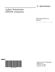
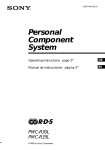
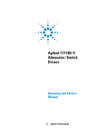
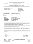
Agilent Technologies
8494/95/96G/H Attenuators
Operating and Service
Manual
Agilent Part Number: 08495-90025
Printed in USA
Print Date: August 2004
Supersedes: July 2002
Notice
The information contained in this document is subject to change without
notice.
Agilent Technologies makes no warranty of any kind with regard to this
material, including, but not limited to, the implied warranties of
merchantability and fitness for a particular purpose. Agilent Technologies
shall not be liable for errors contained herein or for incidental or
consequential damages in connection with the furnishing, performance, or
use of this material.
Agilent Technologies assumes no responsibility for the use or reliability of
its software on equipment that is not furnished by Agilent Technologies.
This document contains proprietary information which is protected by
copyright. All rights are reserved. No part of this document may be
photocopied, reproduced, or translated to another language without prior
written consent of Agilent Technologies.
RESTRICTED RIGHTS LEGEND
Use, duplication, or disclosure by the U.S. Government is subject to
restrictions as set forth in subparagraph (c)(1)(ii) of the Rights in Technical
Data and Computer Software clause at DFARS 252.227-7013 for DOD
agencies, and subparagraphs (c)(1) and (c)(2) of the Commercial Computer
Software Restricted Rights clause at FAR 52.227-19 for other agencies.
Agilent Technologies, Inc.
1400 Fountaingrove Parkway
Santa Rosa, CA 95403-1799, U.S.A.
© Copyright 2000–2002, 2004
Agilent Technologies, Inc.
ii 8494/95/96G/H Operating And Service Manual
What You’ll Find in This Manual…
•
•
•
•
•
•
Overview, page 1
Specifications, page 6
Installation, page 10
Operating Instructions, page 12
Replaceable Parts, page 15
Service, page 16
8494/95/96G/H Operating And Service Manual iii
Warranty
Custom systems are warranted by contractual agreement between Agilent
Technologies and the customer.
Certification
Agilent Technologies, Inc., certifies that this product met its published
specifications at the time of shipment from the factory. Agilent Technologies
further certifies that its calibration measurements are traceable to the
United States National Institute of Standards and Technology (NIST,
formerly NBS), to the extent allowed by the Institute’s calibration facility,
and to the calibration facilities of other International Standards
Organization members.
Documentation
Warranty
THE MATERIAL CONTAINED IN THIS DOCUMENT IS
PROVIDED "AS IS," AND IS SUBJECT TO BEING CHANGED,
WITHOUT NOTICE, IN FUTURE EDITIONS. FURTHER, TO
THE MAXIMUM EXTENT PERMITTED BY APPLICABLE LAW,
AGILENT DISCLAIMS ALL WARRANTIES, EITHER EXPRESS
OR IMPLIED WITH REGARD TO THIS MANUAL AND ANY
INFORMATION CONTAINED HEREIN, INCLUDING BUT NOT
LIMITED TO THE IMPLIED WARRANTIES OF
MERCHANTABILITY AND FITNESS FOR A PARTICULAR
PURPOSE. AGILENT SHALL NOT BE LIABLE FOR ERRORS
OR FOR INCIDENTAL OR CONSEQUENTIAL DAMAGES IN
CONNECTION WITH THE FURNISHING, USE, OR
PERFORMANCE OF THIS DOCUMENT OR ANY
INFORMATION CONTAINED HEREIN. SHOULD AGILENT
AND THE USER HAVE A SEPARATE WRITTEN AGREEMENT
WITH WARRANTY TERMS COVERING THE MATERIAL IN
THIS DOCUMENT THAT CONFLICT WITH THESE TERMS,
THE WARRANTY TERMS IN THE SEPARATE AGREEMENT
WILL CONTROL.
iv 8494/95/96G/H Operating And Service Manual
Service and Support
Product maintenance agreements and other customer assistance agreements
are available for Agilent Technologies products. Any adjustment,
maintenance, or repair of this product must be performed by qualified
personnel. Contact your customer engineer through your local Agilent
Technologies Service Center. You can find a list of local service
representatives on the Web at:
http://www.agilent.com/find/assist
Click on “Contact Us” and select your country.
Safety and Regulatory Information
Review this product and related documentation to familiarize yourself with
safety markings and instructions before you operate the instrument. This
product has been designed and tested in accordance with international
standards.
WARNING
The WARNING notice denotes a hazard. It calls attention to a procedure,
practice, or the like, that, if not correctly performed or adhered to, could result
in personal injury. Do not proceed beyond a WARNING notice until the
indicated conditions are fully understood and met.
CAUTION
The CAUTION notice denotes a hazard. It calls attention to an operating
procedure, practice, or the like, which, if not correctly performed or adhered
to, could result in damage to the product or loss of important data. Do not
proceed beyond a CAUTION notice until the indicated conditions are fully
understood and met.
8494/95/96G/H Operating And Service Manual v
Instrument Markings
!
When you see this symbol on your instrument, you should refer to the instrument’s
instruction manual for important information.
This symbol indicates hazardous voltages.
The laser radiation symbol is marked on products that have a laser output.
This symbol indicates that the instrument requires alternating current (ac) input.
The CE mark is a registered trademark of the European Community. If it is
accompanied by a year, it indicates the year the design was proven.
The CSA mark is a registered trademark of the Canadian Standards Association.
1SM1-A
This text indicates that the instrument is an Industrial Scientific and Medical Group 1
Class A product (CISPER 11, Clause 4).
This ISM device complies with Canadian ICES-001.
Cet appareil ISM est conforme a la norme NMB du Canada.
This symbol indicates that the power line switch is ON.
This symbol indicates that the power line switch is OFF or in STANDBY position.
Safety Earth
Ground
This is a Safety Class I product (provided with a protective earthing
terminal). An uninterruptible safety earth ground must be provided from the
main power source to the product input wiring terminals, power cord, or
supplied power cord set. Whenever it is likely that the protection has been
impaired, the product must be made inoperative and secured against any
unintended operation.
Before Applying
Power
Verify that the product is configured to match the available main power
source as described in the input power configuration instructions in this
manual. If this product is to be powered by autotransformer, make sure the
common terminal is connected to the neutral (grounded) side of the ac power
supply.
vi 8494/95/96G/H Operating And Service Manual
Overview
This manual contains operating instructions for the Agilent 8494G/H,
8495G/H, and 8496G/H attenuators. Included in the manual is information
required to install and test these attenuators.
Specification
Instruments Covered by
Manual
Instrument specifications are indicated in Specifications, page 6. These
specifications are the performance standards or limits against which the
instruments may be tested.
The instruments covered by this manual have a two-part serial number. The
first four digits and letter comprise the serial number prefix. The last five
digits form the sequential suffix that is unique to each instrument. The
contents of this manual apply to instruments with serial prefixes 2544A and
above.
An instrument manufactured after the printing of this manual may have a
serial prefix that is not listed above. This unlisted serial prefix indicates that
the instrument is different from those documented in this manual.
Description
The 8494G/H, 8495G/H, and 8496G/H are 50-ohm coaxial programmable
step-attenuators. Each attenuator is composed of three or four attenuator
sections connected in cascade. Each section consists of a precision, thin-film
attenuator card, a lossless thru-line, and a ganged pair of solenoid-actuated
slab line transmission lines. The slab lines are flexed by the solenoid
plungers to make contact with either the attenuator card or the thru-line. The
slab line contacts are gold plated leaf springs which ensure long life and
extremely high repeatability.
8494/95/96G/H Operating And Service Manual 1
Overview
NOTE
Solenoid (K4) and
associated circuitry
are not available in
models 8495G and
8495H.
Figure 1
Typical Four Section Attenuator Schematic Diagram
Table 1 and Table 2 on page 3 and Table 3 on page 4 show the typical
switching arrangement to increase the amount of attenuation in an 8494G/H,
8495G/H, or 8496G/H in a linear manner. To ensure specified performance,
it is recommended that the attenuator sections that are shown in the
following tables be used. With the attenuator programmed for 0 dB
attenuation, the resultant attenuation is the insertion loss (residual
attenuation). The 8494G/H has a minimum selectable step of 1 dB, while the
8495G/H and 8496G/H have a minimum selectable step of 10 dB. The
accuracy of the attenuators is within the limits given in Specifications,
page 6.
•
The 8494G/H are four-section attenuators with a maximum attenuation
of 11 dB.
•
The 8495G/H are three-section attenuators with a maximum attenuation
of 70 dB.
•
The 8496G/H are four-section attenuators with a maximum attenuation
of 110 dB.
2 8494/95/96G/H Operating And Service Manual
Overview
Table 1
8494G/H Attenuator Switching Order
8494G/H
Attenuator Sections
Atten
(dB)
1
1 dB
2
2 dB
3
4 dB
4
4 dB
0
1
X
2
X
3
X
X
4
X
5
X
6
7
X
X
X
X
X
X
8
9
X
X
X
X
X
X
X
X
X
X
10
11
Table 2
X
X
8495G/H Attenuator Switching Order
8495G/H
Attenuator Sections
Atten
(dB)
1
10 dB
2
20 dB
3
40 dB
0
10
X
20
30
X
X
X
40
50
X
X
60
70
X
X
X
X
X
X
8494/95/96G/H Operating And Service Manual 3
Overview
Table 3
8496G/H Attenuator Switching Order
8496G/H
Attenuator Sections
Atten
(dB)
1
10 dB
2
20 dB
3
40 dB
4
40 dB
0
10
X
20
30
X
X
X
40
50
X
X
60
70
X
X
X
X
X
X
80
90
X
X
X
X
X
X
X
X
X
X
100
110
X
X
Each solenoid requires a drive of 20 to 30 V with a switching current of
approximately 125 mA* at 24 V dc per section. The solenoid switching time
is less than 20 milliseconds including settling time. Once switched, the
solenoid plungers are held in place by permanent magnets and the solenoid
plungers automatically disconnect the selected coil drive and connect the
opposite coil drive (see Figure 1 and Figure 2). This simplifies the coil driver
circuit design and reduces the amount of heat dissipated by the solenoid
coils since the solenoid coils are energized only for the 20 milliseconds
switching time.
*
For serial number prefixes below 1722A, change 125 mA to 110 mA.
4 8494/95/96G/H Operating And Service Manual
Overview
Figure 2
CAUTION
Instrument Options
Typical Solenoid Coil Driver Circuits
Do not exceed the RF power rating of 1 W average or 100 W peak with a
maximum pulse width of 10 µs. Do not connect an attenuator RF input or
output connector to greater the ±7 Vdc. If the attenuator must be connected
to a device with a potential greater than ±7 Vdc, use a blocking capacitor.
Each instrument is specified with an option number which denotes the
configuration of the input and output connectors.
Option
Connector Description
001
Both connectors type-N female
002
Both connectors SMA female
0031
Both connectors 7 mm
1. Option 003 is not available on the 8495G.
8494/95/96G/H Operating And Service Manual 5
Specifications
Specifications
Frequency Range
and Attenuation
Attenuation Accuracy
8494G/H
8495G/H
8496G/H
Attenuation Selection
(dB)
Instrument
Frequency Range
Attenuation
8494G
dc to 4 GHz
0 dB to 11 dB in 1 dB steps
8494H
dc to 18 GHz
0 dB to 11 dB in 1 dB steps
8495G
dc to 4 GHz
0 dB to 70 dB in 10 dB steps
8495H
dc to 18 GHz
0 dB to 70 dB in 10 dB steps
8496G
dc to 4 GHz
0 dB to 110 dB in 10 dB steps
8496H
dc to 18 GHz
0 dB to 110 dB in 10 dB steps
(±dB): (Referenced from 0 dB)
8494G
8494H
8495G
8495H
8496G
8496H
dc–4
GHz
dc–12.4
GHz
12.4–18
GHz
dc–4
GHz
dc–12.4
GHz
12.4–18
GHz
dc–4
GHz
dc–12.4
GHz
12.4–18
GHz
1
10
0.2
0.3
0.7
0.2
0.5
0.6
0.2
0.5
0.6
2
20
0.2
0.3
0.7
0.4
0.7
0.8
0.4
0.7
0.8
3
30
0.3
0.4
0.7
0.5
0.9
1.2
0.5
0.9
1.2
4
40
0.3
0.4
0.7
0.7
1.2
1.6
0.7
1.2
1.6
5
50
0.3
0.5
0.7
0.8
1.5
2.0
0.8
1.5
2.0
6
60
0.3
0.5
0.8
1.0
1.8
2.4
1.0
1.8
2.4
7
70
0.4
0.6
0.8
1.2
2.1
2.8
1.2
2.1
2.8
8
80
0.4
0.6
0.8
-
-
-
1.3
2.4
3.2
9
90
0.4
0.6
0.8
-
-
-
1.5
2.7
3.6
10
100
0.4
0.6
0.9
-
-
-
1.6
3.0
4.0
11
110
0.5
0.7
0.9
-
-
-
1.8
3.3
4.4
6 8494/95/96G/H Operating And Service Manual
Specifications
Maximum SWR
Instrument
Frequency Range (GHz)
Maximum SWR
8495G
dc to 4
1.35
8495H
dc to 8
8 to 12.4
12.4 to 18
1.35
1.5
1.7
8494G,
8496G
dc to 4
1.5
8494H,
8496H
dc to 8
8 to 12.4
12.4 to 18
1.5
1.6
1.9
Maximum Residual
Attenuation
Attenuation Repeatability
RF Power Handling
Capability
Instrument
Maximum Residual Attenuation
8494G,
8494H
0.6 dB + 0.09 dB/GHz
8495G,
8495H
0.4 dB + 0.07 dB/GHz
8496G,
8496H
0.6 d8 + 0.09 dB/GHz
±0.01 dB typical after 5 million cycles
1 W average, 100 W peak with maximum pulse width of 10 microseconds
(all models)
Solenoid Drive
Solenoids Drive
Coil Voltage
Switching Current
All models
(approximately)
20 to 30 Vdc
125 mA1 at 24V
(190Ω, 65mH)
1. For serial number prefixes below 1722S, change 125mA to 110mA.
8494/95/96G/H Operating And Service Manual 7
Specifications
Solenoid Cable Connector
Section
Refer also to Figure 3.
Section 1
Section 2
Section 3
Section 4
Power
Solenoid Coil
Thru-Line
Atten
Card
Thru-Line
Atten
Card
Thru-Line
Atten
Card
Thru-Line
Atten
Card
V+
Cable Wire Color
Code1
PUR
YEL
BLK
GRN
ORN
BLU
BRN
WHT
RED
Connector Plug
Pin Number 2
5
6
7
8
9
10
11
12
1
8494G/H
0dB
1dB
0dB
2dB
0dB
4dB
0dB
4dB
–
8495G/H
0dB
10dB
0dB
20dB
0dB
40dB
–
–
–
8496G/H
0dB
10dB
0dB
20dB
0dB
40dB
0dB
40dB
–
Option 016
13
2
11
5
3
9
4
10
6
Flat Pack
Plug Pin Number3
1. Five-foot cable and mating plug assembly provided.
2. Pin 1 Common solenoid drive (+24 Vdc).
3. Pin 6 is common for all coils. Pins 1, 7, 8, 12 and 14 are not used.
Figure 3
Solenoid Cable Pin Configuration
8 8494/95/96G/H Operating And Service Manual
Specifications
Minimum Life
Switching speed
Environment Limits
>5 million cycles per section
Maximum 20 milliseconds including settling time.
The instrument should be stored in a clean, dry environment. The following
environmental limits apply to storage and shipment, and operation.
Characteristic
Storage and Shipping Value
Operating Value
Temperature
–40 to +75 °C
0 to +55 °C
Humidity
< 95% relative
< 95% relative
Altitude
< 7600 m (25000 ft)
< 4600 m (15000 ft)
Physical Characteristics
Instrument
Dimensions 1
(depth x width x height)
Weight 2
8494G/H
8496G/H
6.25 in x 2.875 in x 1.6875 in
159 mm x 73 mm x 43 mm
16 oz
8495G/H
5.125 in x 2.875 in x 1.6875 in
130 mm x 73 mm x 43 mm
12 oz
454 g
340 g
1. Dimensions are for general information only. If dimensions are required for building special
enclosures, contact your Agilent field engineer.
2. Weight and width of the instrument varies with the option selected due to the type of connectors.
8494/95/96G/H Operating And Service Manual 9
Installation
Installation
Initial Inspection
Inspect the shipping container for damage. If the shipping container or
cushioning material is damaged, it should be kept until the contents of the
shipment have been checked for completeness and the instrument has been
checked mechanically and electrically. A procedure for checking electrical
performance is given under “Operator’s Check” on page 12 (also see
“Performance Tests” on page 14). If the contents of the shipment are
incomplete, if there is mechanical damage or defect, or if the instrument
does not pass the electrical performance test, notify the nearest Agilent
Technologies office. If the shipping container is damaged, or the cushioning
material shows signs of stress, notify the carrier as well as the Agilent office.
Keep the shipping materials for the carrier's inspection. The office will
arrange for repair or replacement without waiting for claim settlement.
NOTE
Containers and materials identical to those used in factory packaging are
available through Agilent Technologies offices. If the instrument is being
returned to Agilent for servicing, attach a tag indicating the type of service
required, return address, model number, and full serial number. Also, mark
the container FRAGILE to assure careful handling. In any correspondence,
refer to the instrument by model number and full serial number.
Mating Connectors
Mating RF connectors used with the Option 001 must be type-N male
connectors, which comply with U.S. military standard MIL-C-39012 (See
Figure 7 on page 19). For Option 002, male SMA connectors must be used.
For Option 003, 7 mm mating connectors must be used (Figure 6 on page
18).
The solenoid drive cable connector plug is a Viking Industries, Inc., part
number TKP12-102-P-TS-100-AU (see Replaceable parts). The connector
plug and contacts without the cable can be ordered from a Viking distributor.
When ordering the complete cable assembly from Agilent, use the part
number listed in Table 5, “Replaceable Parts,” on page 15.
CAUTION
When installing the instrument, make sure that the connectors do not support
weight or bear torque. The preferred procedure is to set up all equipment in
position before connecting the instrument.
10 8494/95/96G/H Operating And Service Manual
Installation
Installation
Instructions
The attenuators may be installed with or without the base. The base is
removed by unscrewing the two fillister head screws from the bottom of the
base. The attenuator may be mounted without the base by inserting two 4-40
screws into the screw holes in the bottom of the attenuator. Removing the
base and mounting the attenuator does not affect the performance of the
attenuator.
The solenoid drive cable connector plug is connected to the attenuator by
aligning the plug (Pl) with the jack (Jl) on the attenuator, and then pushing
the plug over the jack. The plug is removed by grasping the ribbed sides of
the plug and squeezing them together while pulling back until the plug clears
the jack.
8494/95/96G/H Operating And Service Manual 11
Operating Instructions
Operating Instructions
CAUTION
Do not apply RF power greater than 1 W average, or 100 W peak with a
maximum pulse width of 10 microseconds. If these limits are exceeded, the
attenuators may be damaged.
CAUTION
Do not ground both solenoid drive pins at the same time. This causes rapid
cycling of the solenoid and could reduce the operating life of the attenuator.
The rapid cycling may produce a buzzing sound from the attenuator.
Either RF connector may be used as the input or output connector. Connect
the solenoid drive cable to the solenoid drive connector (J1). By applying the
proper voltage and grounds to the proper pins of J1, the attenuator will either
increase or decrease the amount of attenuation as selected.
Operator’s Check
Description
NOTE
The Operator's Check is supplied to allow the operator to make a quick
check of the instrument prior to use or if a failure is suspected.
The attenuator is driven from a 50-ohm signal source at 1 kHz. The output
level from the attenuator is detected by a narrow-bandwidth voltmeter. The
attenuator and detector range switches are stepped together and the
variations in level noted. This verifies that each attenuator section is being
properly switched and checks the low-frequency accuracy of the attenuator.
The SWR meter used in this check is calibrated for a square-law detector and
therefore the range changes and errors (read in dB) are twice that indicated
by the meter.
Figure 4
Operator’s Check Setup
12 8494/95/96G/H Operating And Service Manual
Operating Instructions
Procedure
1. Connect equipment as shown in Figure 4 on page 12 with the attenuator
set to 0 dB attenuation.
2. Set the test oscillator to 0.3 Vrms at 1 kHz.
3. Set SWR meter range to 2 dB (expanded) [or for the 8494G/H to 10 dB
(expanded)] and adjust its bandwidth to center of adjustment range. Fine
tune oscillator frequency to obtain maximum meter indication.
4. Set attenuator and SWR meter range switch as listed in Table 4 and
verify that SWR meter indicates within limits shown.
Table 4
SWR Meter Range
(dB)
Attenuator and SWR Settings
Attenuation (dB)
Meter Indication (dB)
Minimum
Actual
Maximum
8494G/H
8495G/H
8496G/H
8494G/H
8495G/H
8496G/H
8494G/H
8495G/H
8496G/H
8494G/H
8495G/H
8496G/H
8494G/H
8495G/H
8496G/H
10
2
0
0
0
-
-
Set to 0.0
Set to 0.5
-
-
10
6
1
10
10
0.40
1.40
-
-
0.60
1.60
10
12
2
20
20
0.90
0.30
-
-
1.10
0.70
10
16
3
30
30
1.35
1.25
-
-
1.65
1.75
10 1
22
4
40
40
1.85
0.15
-
-
2.15
0.85
12
26
5
50
50
0.35
1.10
-
-
0.65
1.90
12
32
6
60
60
0.85
0.00
-
-
1.15
1.00
12
36 1
7
70
70
1.30
0.90
-
-
1.70
2.10
12 1
42 1
8
-
80
1.80
–0.15
-
-
2.20
1.15
14
46 1
9
-
90
0.30
0.75
-
-
0.70
2.25
14
52 1
10
-
100
0.80
–0.30
-
-
1.20
1.30
14
56 1
11
-
110
1.75
0.60
-
-
1.75
2.40
1. Adjust range by 2 dB, if needed, to obtain a on-scale indication.
8494/95/96G/H Operating And Service Manual 13
Operating Instructions
Performance Tests
The instrument can be tested to the accuracy of the “Specifications” on
page 6, with an automatic network analyzer or equivalent equipment of
suitable accuracy. If an automatic network analyzer is available, test the
instrument using the procedures in the analyzer's operating manual.
Refer to the Agilent 11713A Attenuator/Switch Driver Operating and
Service Manual for programming instructions.
Adjustments
The attenuators have no internal adjustments and should not be opened. If
defective, return the attenuator to the nearest Agilent Technologies office for
repair.
14 8494/95/96G/H Operating And Service Manual
Replaceable Parts
Replaceable Parts
Table 5 lists the replaceable parts which are the only parts that can be
replaced without access to the interior of the instrument. If any parts not
listed below need replacement, return the instrument to Agilent
Technologies.
To order a part listed in the replaceable parts table below, quote the part
number, indicate the quantity required, and address the order to the nearest
Agilent Technologies office.
CAUTION
Due to special fixtures necessary for assembly, do not attempt to replace any
parts not listed in the table below. If the instrument is opened, the warranty is
void.
Table 5
Replaceable Parts
Description
Part Number
Option 003 7-mm center conductor contact
1250-0907
Option 003 7-mm connector outer shell assembly
1250-0909
Option 001 type-N female connector outer shell
1250-0914
Screws for both bases: 4-40 x 7/8 in. Fillister head
2220-0006
Cable, solenoid drive, 1.52 m (5 ft) long, connector plug on
one end and other end unterminated
8120-2178
Base for 8495G/H
5041-3887
Base for 8494G/H and 8496G/H
5041-3888
Connector plug and contacts only without cable
TKP12-12-102P-TS-100-AU1
Contact insertion/extraction tool
TIE-2001
1. Available from distributors of Viking Industries, Inc., Chatsworth CA 91311
8494/95/96G/H Operating And Service Manual 15
Service
Service
Troubleshooting
Troubleshooting consists of performing the “Operator’s Check” on page 12.
If the instrument does not perform within limits, return the instrument to
Agilent Technologies.
Repair
The only recommended field repair is replacing the outer connector shell for
the Option 001 and 003, or replacing the center contact in the 7 mm
connector. For any other repair, return the entire instrument to Agilent
Technologies.
Replacing the 7 mm
Connector Center
Conductor Contact
Figure 5
Making the Connection
The replacement procedure for the 7 mm connector center contact is covered
in Figure 6 on page 18. The disassembly and assembly instructions for the
7 mm connector are covered in Figure 5.
7 mm Connector
1. On one connector, retract the coupling sleeve by turning the coupling nut
counterclockwise until the sleeve and nut disengage.
2. On the other connector, fully extend the coupling sleeve by turning the
coupling nut clockwise. To engage coupling sleeve and coupling nut
when the sleeve is fully retracted, press back lightly on the nut while
turning it clockwise.
3. Push the connectors firmly together, and thread the coupling nut of the
connector with retracted sleeve over the extended sleeve.
16 8494/95/96G/H Operating And Service Manual
Service
4. Close the gap between coupling nut with the nut on the extended-sleeve
connector.
To disconnect:
1. Loosen the coupling nut of the connector showing the wider gold band.
CAUTION
Part the connectors carefully to prevent striking the inner conductor contact.
To care for the device:
1. Keep contacting surfaces smooth and clean. Irregularities and foreign
particles can degrade electrical performance.
2. Protect the contacting surfaces when the connector is not in use by
leaving the coupling sleeve extended.
3. Use lintless material and/or firm-bristles brush such as a tooth brush for
cleaning. If a cleaning fluid is needed, use isopropyl alcohol.
8494/95/96G/H Operating And Service Manual 17
Service
CAUTION
Do not use aromatic or chlorinated hydrocarbons, esters, ethers, terpenes,
higher alcohols, ketones, or ether-alcohols such as benzene, toluene,
turpentine, dioxane, gasoline, cellosolve acetate, or carbon tetrachloride.
Keep exposure of the connector parts to both the cleaning fluid and its
vapors as brief as possible.
Replacing Amphenol
7 mm Center Contact
CAUTION
Through wear or damage, the contact in the 7 mm center conductor may
need replacement. This contact is a small four-pronged contact which snaps
into a recess in the center conductor. With a magnifying glass, examine the
contact for the necessary outward spring action by carefully pushing it in.
Do not remove this contact for inspection. It may be damaged by removal.
The prongs of the contact should be free from burrs or wear. If the contact is
removed, do not reuse it. Order contact as Amphenol part number 131-129*
or Agilent part number 1250-0907.
Figure 6
7 mm Connector
If this contact needs replacement, proceed as follows:
1. Place the instrument so the connector faces down, if possible.
2. Tap the connector lightly. The contact should now protrude slightly.
Insert the centering pin of the Agilent collet remover with the jaws open.
(Part number of the contact extractor is 5060-0370.) If this tool is not
available, an ordinary draftsman’s mechanical pencil may be used (the
end of the jaw may have to be filed to get a good grasp at the very end).
*
Amphenol RF Division, Danbury, CN.
18 8494/95/96G/H Operating And Service Manual
Service
3. Allow the jaws of the tool used to close and pull straight back from the
connector without twisting. The contact should come with the tool. If
not, repeat the process. Do not reuse the contact.
4. Snap in a new contact by pushing it in place. Test the action of the new
contact by pushing it in. It should spring out again when released.
Type N Connector
Dimensions
Figure 7
For critical dimensions for the type-N connector, see below.
Type-N Connector
Replacing the
Connector Outer Shell
NOTE
The connector outer shell can be replaced only on the Option 001 (type-N
female) or the Option 003 (7 mm). The outer shell on the Option 002 (SMA)
cannot be replaced in the field. If these connectors are damaged, return the
instrument to Agilent Technologies for repair.
The connector outer shells on the 0ption 001 and 003 may be replaced as
follows:
1. With a 9/16-inch (1/2-inch for 7 mm) thin open-end wrench, unscrew the
outer connector body.
2. Replace the connector outer shell. See Table 5 on page 15 for
replaceable parts numbers.
3. Tighten the connector with the same wrench called out in step 1.
8494/95/96G/H Operating And Service Manual 19