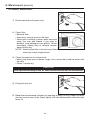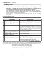
1
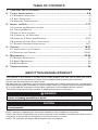
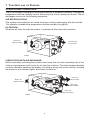
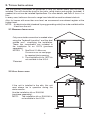
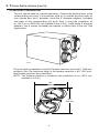
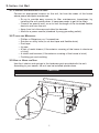
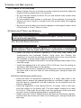
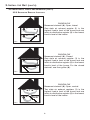
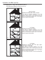
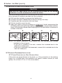
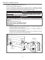
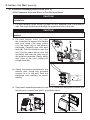
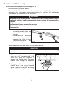
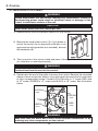
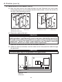
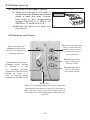
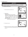
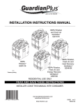
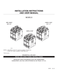
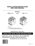
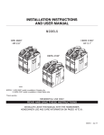
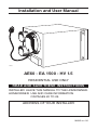
Installation and User Manual
VB0063
AE60 - EA 1500 - HV 1.5
RESIDENTIAL USE ONLY
READ AND SAVE THESE INSTRUCTIONS
INSTALLER: LEAVE THIS MANUAL TO THE HOMEOWNER.
HOMEOWNER: USE AND CARE INFORMATION
ON PAGES 20 TO 24.
ADDRESS OF YOUR INSTALLER
06095 REV. 05
! WARNING
TO REDUCE THE RISK OF FIRE, ELECTRIC SHOCK, OR PERSONAL INJURY
OBSERVE THE FOLLOWING:
1. This unit is intented for residential installation only.
2. Use this unit only in the manner intended by the manufacturer. If you have questions, contact
the manufacturer at the address or telephone number listed in the warranty.
3. Before replacing filters, servicing or cleaning unit, disconnect power cord from electrical outlet.
4. Installation must be done in accordance with all applicable codes and standards, including
fire-rated construction codes and standards.
5. This unit is not designed to provide combustion and/or dilution air for fuel-burning appliances.
6. When cutting or drilling into wall or ceiling, do not damage electrical wiring and other hidden
utilities.
7. Do not use this unit with any solid-state speed control device other than optional controls C34,
CMR or ACCGSC3.
8. This unit must be grounded. The power supply cord has a 3-prong grounding plug for your
personal safety. It must be plugged into a mating 3-prong grounding receptacle, grounded in
accordance with the national electrical code and local codes and ordinances. Do not remove the
ground prong. Do not use an extension cord.
9. Do not install in a cooking area or connect directly to any appliances.
10. Do not use to exhaust hazardous or explosive materials and vapors.
11. Do not run any air ducts directly above or closer than 2 ft (0.61 m) to any furnace or its supply
plenum, boiler, or other heat producing appliance. Do not connect the unit ducts to the furnace
ducts, neither return plenum or supply.
12. When performing installation, servicing or cleaning the unit, it is recommended to wear safety
glasses and gloves.
13. When applicable local regulations comprise more restrictive installation and/or certification
requirements, the aforementioned requirements prevail on those of this document and the
installer agrees to conform to these at his own expenses.
14. This product employs overload protection (fuse). A blown fuse indicates an overload or
shortcircuit situation. If the fuse blows, unplug the product from the outlet. Replace the fuse as
per the servicing instructions (follow product marking for proper fuse rating) and check the
product. If the replacement fuse blows, a short-circuit may be present and the product should be
discarded or returned to an authorized service facility for examination and/or repair.
15. Do not operate any fan with a damaged cord or plug. Discard fan or return to an authorized
service facility for examination and/or repair.
16. Do not run cord under carpeting. Do not cover cord with throw rugs, runners, or similar coverings.
Do not route cord under furniture or appliances. Arrange cord away from traffic area and where
it will not be tripped over.
CAUTION
1. To avoid premature clogged filters, turn OFF the unit during construction or renovation.
2. Please read specification label on product for further information and requirements.
3. Be sure to duct air outside – Do not intake/exhaust air into spaces within walls or ceiling or into
attics, crawl spaces, or garage.
4. Intended for residential installation only in accordance with the requirements of NFPA 90B.
5. The ductwork is intended to be installed in compliance with all local and national codes that are
applicable.
6. Do not use the AE60, EA 1500 or HV 1.5 unit when varnishing. Furthermore, if the unit is installed
in the attic, it is highly recommended to block the stale air intake and fresh air register. The varnish
vapors may damage the unit.
7. At least once in a year, the unit mechanical and electronic parts should be inspected by qualified
service personnel.
8. If the unit is installed in the attic, it should not be turned off during the winter time in order to
avoid condensation inside the unit and inside the ducts.
9. During snow/rain storm, operate the unit in recirculation mode to prevent water build up in the
ventilator.
2
TABLE OF CONTENTS
1. YOUR UNIT AND ITS PURPOSE..........................................................................4
2. TYPICAL INSTALLATIONS .............................................................................. 5-6
2.1 BASEMENT INSTALLATION ........................................................................................ 5
2.2 ATTIC INSTALLATION............................................................................................... 5
2.3 MOUNTING CONSIDERATIONS .................................................................................. 6
3. INSTALL THE UNIT .....................................................................................7-17
3.1 LOCATING AND MOUNTING THE UNIT ........................................................................ 7
3.2 TOOLS AND MATERIAL ........................................................................................... 7
3.3 HOW TO HANG THE UNIT ....................................................................................... 7
3.4 PLANNING OF THE DUCTWORK ................................................................................ 8
3.5 INSTALLING 6” DUCTS AND REGISTERS ................................................................ 8-10
3.6 INSULATED FLEXIBLE DUCTS INSTALLATION ...............................................................11
3.7 EXTERIOR OPENING(S) INSTALLATION ................................................................. 11-17
4. CONTROL ............................................................................................. 18-21
4.1 INSTALLATION OF THE CONTROL ........................................................................ 18-20
4.2 OPERATING THE CONTROL .............................................................................. 20-21
5. MAINTENANCE ....................................................................................... 22-24
5.1 BIANNUAL MAINTENANCE ..................................................................................... 22
5.2 ANNUAL MAINTENANCE ........................................................................................ 23
5.3 MASTER RESET ................................................................................................. 24
6. TROUBLESHOOTING ......................................................................................24
ABOUT THIS MANUAL/PRODUCT
The purpose of this manual is to help you to install properly your unit, and to show you how to
operate and do the maintenance. Please read completely before starting the installation.
Please note the illustrations are typical ones.
We welcome any suggestions you may have concerning this manual and/or the unit, and we would
appreciate hearing your comments on ways to better serve you. Please forward all correspondence
to us at the address indicated on the product registration card included with this manual.
This manual uses the following symbols to emphasize particular information:
! WARNING
Identifies an instruction which, if not followed, might cause serious personal
injuries including possibility of death.
CAUTION
Denotes an instruction which, if not followed, may severely damage the unit and/or
its components.
NOTE: Indicates supplementary information needed to fully complete an instruction.
Finally, we want to congratulate you on your purchase of this excellent unit which will allow you and
your family to enjoy fresh air throughout your home for years to come!
NOTE: The unit does not require balancing because of its design.
3
1. YOUR UNIT AND ITS PURPOSE
OPERATIONAL PRINCIPLES
The air exchanger is designed to eliminate problems of excessive humidity, to steady the
temperature and the humidity and to filter and purify the air inside your house. The air
exchanger carries out the following operations:
AIR RECIRCULATION:
The system recirculates the air inside the house, without exchanging with the outside.
This operation steadies the temperature and the humidity throughout.
FILTRATION:
When the air flows through the system, a mechanical filter traps dust particles.
STALE AIR
FILTERED AIR
FROM BUILDING
TO BUILDING
VF0035
CIRCULATION WITH AIR EXCHANGE:
While continually circulating the air within the house, the unit also evacuates part of this
stale air and replaces it with fresh dry air from the outdoors. The following extra benefits
are thus obtained: expelling the excess of humidity during the winter months, ventilate
the house on hot summer nights, elimination of stale air.
FRESH AIR
TO BUILDING
STALE AIR
FROM BUILDING
STALE AIR
TO OUTDOORS
FRESH AIR
FROM OUTDOORS
VF0034
4
2. TYPICAL INSTALLATIONS
Use the following illustrations as guidelines to help you decide where your unit will be
installed. The unit should be hung to the joists, using chains and springs (included). If
needed, this unit can be installed upside down. For more details, see Point 3. INSTALL THE
UNIT.
In every case, bathroom fan and a range hood should be used to exhaust stale air.
Also, for homes with more than one level, we recommend one exhaust register at the
highest level.
NOTE: An electrical outlet (standard 3-prong grounding outlet) has to be available within
3 feet from the unit.
2.1 BASEMENT INSTALLATION
Only one outside connection is needed when
using the Tandem® transition* and the dual
outside port*, simplifying the installation.
These two components are included in
the installation kit no. 15273 (purchase
separately).
NOTES: 1. See Point 2.3 MOUNTING
CONSIDERATIONS on next page
for required joists opening.
2. The installation kit no. 15273 is
not available in the U.S.A.
*Patented.
VH0053
2.2 ATTIC INSTALLATION
If the unit is installed in the attic, this unit
must always be in operation during the
winter season.
Use the installation kit no. EA20130
(purchase separately).
NOTE:
The installation kit no. EA20130 is
not available in the U.S.A.
VH0004
5
2. TYPICAL INSTALLATIONS (CONT’D)
2.3 MOUNTING CONSIDERATIONS
This unit can be used for a retrofit application. Connect the existing ducts to the
corresponding unit ports. If the previous stale air to outside duct and fresh air
from outside duct are 5’’ diameter, install the 5’’ diameter adapters (included)
over each of the corresponding unit ports. Also, if using the installation kit
no. 15273 or no. EA20130 (not available in the U.S.A.), install these 5’’ diameter
adapters. Use 4 screws (included) per adapter to attach them to the unit. See
figure below.
VJ0030
The joists opening needed to install the Tandem transition must be 9¾’’ (248 mm)
minimum. Also, the maximum heigh of the tandem transition is 8¾’’ (222 mm).
See Tandem transition end view below.
NOTE: The Tandem transition is included in the installation kit no. 15273 (not
available in U.S.A.).
9¾”
248 mm
8¾”
222 mm
VD0118A
6
3. INSTALL THE UNIT
3.1 LOCATING AND MOUNTING THE UNIT
Choose an appropriate location for the unit, far from the areas of the house
where peace and quiet are desired.
• So as to provide easy access for filter maintenance (sometimes, by
installing the unit upside down, it becomes easier to get to the filter).
• Close to an exterior wall, so as to limit the length of the insulated flexible
ducts to and from the unit.
• Away from hot chimneys and other fire hazards.
• Allow for a power source (standard 3-prong grounding outlet).
3.2 TOOLS AND MATERIALS
•
•
•
•
•
Phillips or Robertson no. 2 screwdriver
Scissors or utility knife (to cut duct tape and flexible ducts)
Duct tape
Jig saw
A pair of metal shears (if the exterior covering of the house is aluminum
or vinyl)
• A chisel and hammer (if the exterior covering of the house is brick)
• Caulking gun and caulking
3.3 HOW TO HANG THE UNIT
Use the 4 chains and springs in the hardware pack provided with the unit.
According to your needs, the unit can be installed upside down.
CAUTION
Make sure the unit is level.
VD0156
7
3. INSTALL THE UNIT (CONT’D)
3.4 PLANNING OF THE DUCTWORK
• Keep it simple. Plan for a minimum number of bends and joints. Keep the
length of the insulated ducts to a minimum.
• Do not use wall cavities as ducts. Do not use branch lines smaller than
4’’ (102 mm) diameter.
• Do not ventilate crawl spaces or cold room. Do not attempt to recover the
exhaust air from a dryer or a range hood, this would cause the clogging
of the unit.
• Be sure to plan at least one exhaust register on the highest lived-in level
of the house, if it has 2 floors or more.
3.5 INSTALLING 6” DUCTS AND REGISTERS
CAUTION
If ducts have to go through an unconditioned space, always use insulated
ducts (purchase separately).
3.5.1 STALE AIR EXHAUST DUCTWORK
! WARNING
Never install a stale air exhaust register in a room where a combustion
device operates, such as a gas water heater, a gas furnace or a fireplace.
• Install the stale air exhaust register(s) in the main area where the
contaminants are produced: kitchen, living room, etc. Position the
register(s) as far from the stairway as possible and in such a way that the
air circulates in all the lived-in spaces in the house.
• If a register is installed in the kitchen, it must be located at least 4 feet (1.2 m)
from the range.
• Install the register(s) 6 to 12 inches (152 to 305 mm) from the ceiling on
an interior wall OR install it in the ceiling.
• Attach one end of the 6’’ flexible duct to the stale air exhaust register, and
the other end to the unit stale air from building port, using tie wrap and
duct tape.
3.5.2 FRESH AIR DISTRIBUTION DUCTWORK
• Install the fresh air distribution register(s) in a large, open area in the
lowest level to ensure the greatest possible air circulation. Keep in mind
that the fresh air register(s) must be located as far as possible from the
stale air register(s).
• Install the register(s) in the ceiling OR 6 to 12 inches (152 to 305 mm)
from the ceiling on an interior wall. The duct length should be at least
15’ (4.6 m). (The cooler air will then cross the upper part of the room and
mix with room air before descending to occupant level.)
• Attach one end of the 6’’ flexible duct to the fresh air distribution register,
and the other end to the unit fresh air to building port, using tie wrap and
duct tape.
8
3. INSTALL THE UNIT (CONT’D)
3.5 INSTALLING 6” DUCTS AND REGISTERS (CONT’D)
3.5.3 SUGGESTED REGISTER LOCATIONS
1
A
BUNGALOW
Basement stairwell (A): Open, lateral.
One stale air exhaust register (1) in the
highest lived-in level of the house and one
fresh air distribution register (2) in the lowest
lived-in level of the house.
A
BUNGALOW
Basement stairwell (A): Closed.
One stale air exhaust register (1) in the
highest lived-in level of the house and one
fresh air distribution register (2) in the lowest
lived-in level of the house. For the closed
stairwell, use floor grilles (A).
2
VA0032
1
2
VA0033
BUNGALOW
Basement stairwell (A): Open, central.
Two stale air exhaust registers (1) in the
highest lived-in level of the house and one
fresh air distribution register (2) in the lowest
lived-in level of the house.
1
2
A
VA0034
9
3. INSTALL THE UNIT (CONT’D)
3.5 INSTALLING 6” DUCTS AND REGISTERS (CONT’D)
3.5.3 SUGGESTED REGISTER LOCATIONS (CONT’D)
1
MULTI-LEVEL
Basement stairwell (A): Open, central.
Two stale air exhaust registers (1) in the
upper lived-in levels of the house and one
fresh air distribution register (2) in the lowest
lived-in level of the house.
1
A
2
VA0035
COTTAGE
Basement stairwell (A): Open.
Two stale air exhaust registers (1) in the
upper lived-in levels of the house and one
fresh air distribution register (2) in the lowest
lived-in level of the house.
1
A
1
A
2
VA0036
1
A
B
B
COTTAGE
Basement stairwell (A): One part open,
some parts closed (B).
One stale air exhaust register (1) in the
highest lived-in level of the house and one
fresh air distribution register (2) in the lowest
lived-in level of the house.
For the closed stairwell, use floor grilles (B).
2
VA0037
10
3. INSTALL THE UNIT (CONT’D)
3.6 INSULATED FLEXIBLE DUCTS INSTALLATION
CAUTION
Make sure the vapor barrier on the insulated ducts does not tear during
installation to avoid condensation within the ducts.
Use the following procedure for connecting the insulated flexible ducts to the unit
ports (exhaust to outdoors and fresh air from outdoors).
a) Pull back the insulation to expose the flexible duct.
b) Connect the interior flexible duct to the port using a tie wrap.
c) Carefully seal the connection with duct tape.
d) Pull the insulation over the joint.
e) Apply duct tape to the joint making an airtight seal. Avoid compressing the
insulation when pulling the tape tightly around the joint; compressed insulation
loses its R value and causes water dripping due to condensation on the exterior
surface of the duct.
a)
b)
c)
d)
e)
VJ0010
NOTE: In a retrofit installation, there maybe only one insulated duct already
installed for the unit ports.
• If the unit is installed in the attic, connect this insulated duct to the
exhaust to outdoor port.
• If the unit is installed in the basement, connect this insulated duct to the
fresh air intake port.
3.7 EXTERIOR OPENING(S) INSTALLATION
3.7.1 TANDEM TRANSITION WITH DUAL EXTERIOR HOOD
If the joists are perpendicular to the ducts, or if the connection to the exterior
hood is in a limited area, the installation will need 2 exterior hoods (or soffit
grilles). Go to Point 3.7.2 or 3.7.4 for more details.
11
3. INSTALL THE UNIT (CONT’D)
3.7 EXTERIOR OPENING(S) INSTALLATION (CONT’D)
3.7.1 TANDEM TRANSITION WITH DUAL EXTERIOR HOOD (CONT’D)
1. For each duct, pull back the insulation to expose the interior flexible duct.
CAUTION
Always connect the exhaust air to outside duct on top section of the
Tandem transition.
2. Connect the interior flexible duct to the smaller part of the Tandem transition
(5’’ oval) using a tie wrap.
3. Pull the insulation over the joint. Pull the vapor barrier over the insulation.
4. Apply duct tape gently to the joint in order to make an airtight seal. See
figures below.
2
1
EXHAUST AIR
TO OUTDOORS DUCT
ON TOP SECTION
VJ0022
VJ0025
3
4
VJ0023
VJ0024
Dual exterior hood requires assembly. Using 2 no. 8 x 3/4” screws, assemble the
top metal screen and the plastic grille to the dual exterior hood. Then, slide the
bottom metal screen to the dual exterior hood. See illustration below.
VO0024
12
3. INSTALL THE UNIT (CONT’D)
3.7 EXTERIOR OPENING(S) INSTALLATION (CONT’D)
3.7.1 TANDEM TRANSITION WITH DUAL EXTERIOR HOOD (CONT’D)
The dual exterior hood must be installed at a minimum
distance of 18 inches (457 mm) from the ground.
See illustration at right.
18”
(457 mm)
VD0083A
! WARNING
Make sure this hood is at least 6 feet (1.8 m) away (or more, as per
applicable building codes or standards) from sources of contamination
such as:
• High efficiency furnace vent
• Any exhaust from a combustion source
• Gas meter exhaust, gas barbecue-grill
• Garbage bin
1
1. Using a jig saw, cut a 6’’ diameter
hole in the exterior wall and insert
the Tandem transition through this
hole.
VD0084
1) EXHAUST AIR TO OUTDOORS DUCT
CAUTION
The Tandem transition must be inserted in such way that the exhaust air
to outdoors duct will be located on the top.
13
3. INSTALL THE UNIT (CONT’D)
3.7 EXTERIOR OPENING(S) INSTALLATION (CONT’D)
3.7.1 TANDEM TRANSITION WITH DUAL EXTERIOR HOOD (CONT’D)
XMAS TREE PIN
2. Join the end of the Tandem transition
to the rear of the exterior backplate.
Secure with 2 Xmas tree pins and
seal properly with duct tape.
VD0085
CAUTION
The exterior backplate must be installed with the word “TOP” pointing
upward.
3. Lean the exterior backplate to the
exterior wall.
Using 4 no. 8 x 1½” screws, mount it
to the wall. Seal the outline with
caulking.
VD0086
4. Snap the assembled exterior hood
on its backplate and secure with
2 provided screws (no. 8 x 3/4” long).
VD0087
14
SCREW
3. INSTALL THE UNIT (CONT’D)
3.7 EXTERIOR OPENING(S) INSTALLATION (CONT’D)
3.7.2 LOCATING TWO EXTERIOR HOODS
If this unit installation needs to have 2 exterior hoods, an additional exterior
hood must be bought (sold separately, single exterior hood, part number 13940).
Choose an appropriate location for installing the exterior hoods.
CAUTION
Due to its particular design, the dual exterior hood must be used only for
exhaust hood when performing an installation using 2 exterior hoods.
Use the single exterior hood for supply air.
! WARNING
Make sure the single exterior hood is at least 6 feet (1.8 m) away (or more, as
per applicable building codes or standards) from sources of contamination
such as:
• High efficiency furnace vent
• Any exhaust from a combustion source
• Gas meter exhaust, gas barbecue-grill
• Garbage bin
• The dual exterior hood must be located at a minimum distance of
4 inches (102 mm) from the ground.
• The single exterior hood must be located at a minimum distance of
18 inches (457 mm) from the ground.
• There must be a minimum distance of 6 feet (1.8 m) between the hoods
to avoid cross-contamination. See figure below.
INTAKE
EXHAUST
OPTIONAL
LOCATION
HOOD
HOOD
6’
(1.8 M)
18”
(457 MM)
6’
(1.8 M)
4”
(102 MM)
4” (102 MM)
VD0094
15
3. INSTALL THE UNIT (CONT’D)
3.7 EXTERIOR OPENING(S) INSTALLATION (CONT’D)
3.7.3 CONNECTING INSULATED DUCTS TO TWO EXTERIOR HOODS
CAUTION
Make sure the insulated ductwork vapor barrier does not tear during
installation.
1. For each exterior hood, using a jig saw, cut a 6’’ diameter hole in the exterior
wall. Run each flexible duct through its respective hole in the wall.
CAUTION
The exterior backplate must be installed with the word “TOP” pointing
upward.
2. For each exterior hood, pull back
the insulation to expose the flexible
duct and, using a tie wrap, attach
it to the inner ring of the exterior
backplate. Carefully seal with duct
tape (A). Pull the insulation over the
joint. Pull the vapor barrier over the
insulation and over the outer ring of
the exterior backplate. Gently apply
duct tape to the joint making an
airtight seal (B).
B
A
VD0095
3. Attach the exterior backplate to the
exterior wall. Using four provided
screws, fix it to the wall. Seal the
backplate with caulking, as shown
beside.
VD0096
4. Snap each assembled exterior hood on its respective backplate location and
secure each of them with their 2 provided screws.
VD0087
SCREW
VD0097
16
SCREW
3. INSTALL THE UNIT (CONT’D)
3.7 EXTERIOR OPENING(S) INSTALLATION (CONT’D)
3.7.4 LOCATING TWO SOFFIT GRILLES
If this unit is installed in the attic, use the installation kit no. EA20130 (not available
in the U.S.A.). Choose an appropriate location for installing the soffit grilles
(included in the installation kit no. EA20130).
! WARNING
Make sure the air intake grille is at least 6 feet (1.8 m) away (or more, as per
applicable building codes or standards) from sources of contamination
such as:
• High efficiency furnace vent
• Any exhaust from a combustion source
• Gas meter exhaust, gas barbecue-grill
• Garbage bin
• Do not locate where
prevailing winds blow the
stale air towards the fresh
air vent.
• There must be a minimum
distance of 6 feet (1.8 m)
between the grilles to avoid
cross-contamination. See
illustration at right.
6’ (1.
8 M)
VD0160
3.7.5 CONNECTING INSULATED DUCTS TO TWO SOFFIT GRILLES
CAUTION
Make sure the insulated ductwork vapor barrier does not tear during
installation.
1. For each exterior hole, using a jig
saw, cut a 4¼’’ diameter hole in the
soffit. Pull back the insulation to
expose the flexible duct. Run each
flexible duct through its respective
hole.
2. Using provided screws, attach the
flexible duct to the ring of the soffit
grille. Carefully seal with duct tape.
Assemble the soffit grilles to the soffit.
17
VI0014
4. CONTROL
4.1 INSTALLATION OF THE CONTROL
! WARNING
Always disconnect the unit before making any connections. Failure in
disconnecting power could result in electrical shock or damage of the
control or electronic module of the unit.
CAUTION
Never install more than one control per unit.
1. Determine the more convenient location for the control.
2
2. Remove the cover plate control (1). If you prefer to
mount the control on an approved outlet box or an
approved mounting bracket (not included), discard
the backplate (2).
1
3. Take one end of the control cable and pass it through the control backplate
(or outlet box or mounting bracket).
! WARNING
To avoid risk of electrical shocks, never install another wire in the same
electrical box than the one for the control.
4. Splice back this end of the cable to access the 4 wires. Remove the insulated
sleeve of each wire ends. Make a loop with each bare end wire to hook them
to their corresponding screw. Connect YELLOW wire to “Y” screw, RED wire
to “R” screw, GREEN to “G” screw and BLACK to “B” screw. See illustration
below.
BLACK
WIRE
YELLOW
WIRE
RED
GREEN
WIRE
WIRE
! WARNING
Make sure that the wires don’t short circuit between themselves or by
touching any other components on the control.
18
4. CONTROL (CONT’D)
4.1 INSTALLATION OF THE CONTROL (CONT’D)
5. Run the other end of the cable through the wall. Reinstall the cover plate.
Using wall anchors (not included) and provided screws, mount the control on
the wall. See illustrations below.
1
3
2
1
4
2
3
5
4
VC0051
VC0052
1 WALL ANCHORS
2 CONTROL CABLE
3 CONTROL BACKPLATE
4 CONTROL
5 SCREWS
1 OUTLET BOX
2 CONTROL CABLE
3 CONTROL
4 SCREWS
6. Route the cable to the unit.
CAUTION
Keep control low voltage wiring at least 1 foot (305 mm) away from motors,
lightning ballast, light dimming circuit and power distribution panel. Do
not route control wiring along with house power wiring. Avoid poor wiring
connections. Failure to follow these practices can introduce electrical
interference, which can cause erratic control operations.
7. Remove the electrical box cover on the side of the unit.
8. Slide the sleeve (included) over the cable control and pass the cable through
the grommet.
CAUTION
The sleeve must stay in the grommet. See figure below.
1
2
3
VD0157
1 CONTROL CABLE
2 SLEEVE
3 GROMMET
19
4. CONTROL (CONT’D)
4.1 INSTALLATION OF THE CONTROL (CONT’D)
9. Splice back the end of the cable to
access the 4 wires.Remove the insulated
sleeve of each wire ends. Connect
each wires in their corresponding
terminal (YELLOW in “Y”, RED in “R”,
GREEN in “G” and BLACK in “B”).
10. Reinstall the electric box cover and
plug the unit.
G B
Y R
VE0083
4.2 OPERATING THE CONTROL
RECIRCULATION INDICATOR:
UNIT IS OPERATING ON
FRESH AIR INDICATOR:
LIGHTS UP WHEN SLIDE
NORMAL SPEED WITHOUT
SWITCH IS ON MINIMUM OR
EXCHANGING AIR WITH
MAXIMUM POSITION.
THE OUTDOORS.
MAXIMUM INDICATOR:
UNIT IS OPERATING
ON HIGH SPEED.
MAINTENANCE INDICATOR:
FLASHES EVERY SECOND
TO
TO
INDICATE
IT
PERFORM
IS
MINIMUM INDICATOR:
UNIT IS OPERATING
ON NORMAL SPEED.
TIME
BIANNUAL
MAINTENANCE. SEE SECTION 5.
LIGHTS
UP
WHEN
IT
IS
TIME TO PERFORM ANNUAL
MAINTENANCE. SEE SECTION 5.
VC0114
RESET HOLE:
ONCE THE FILTER MAINTENANCE IS DONE, RESET THE
MAINTENANCE INDICATOR BY CAREFULLY INSERTING A
SMALL ROD (E.G.: PAPER CLIP) IN THE RESET HOLE FOR
1 SECOND. THE FILTER MAINTENANCE INDICATOR WILL
TURN OFF.
20
4. CONTROL (CONT’D)
4.2 OPERATING THE CONTROL (CONT’D)
• “O”:
To stop the unit, slide the button on this position.
• MINIMUM:
For a day-to-day usage, slide the button on this position.
The unit then will operate on normal speed.
• MAXIMUM:
For a high speed operation, slide the button on this position.
Generally used when extreme conditions occur, e.g.: parties,
smokers, etc.
• RECIRCULATION: For a normal speed operation, without exchanging air with
the outdoors, slide the button on this position. This mode is
recommended in high humidity days (rain, heat wave).
Also, use it when the outside temperature is extremely cold
and/or the inside air is too dry. It can be used also to
recirculate the heat coming from a wood stove throughout
the house, or the fresh air from a cooling system.
21
5. MAINTENANCE
! WARNING
Risk of electrical shocks. Before performing any maintenance or servicing,
always disconnect the unit from its power source. It is recommended to wear
safety glasses and gloves when performing maintenance or servicing.
5.1 BIANNUAL MAINTENANCE
1. Disconnect the unit power cord.
VD0005
2. Clean filter
• Remove filter.
• Vacuum to remove most of the dust.
• Wash with a mixture of warm water and mild
soap. You may add bleach if you wish to
disinfect (one tablespoon per gallon). Rinse
thoroughly. Shake filter to remove excess
water and let dry.
NOTE: Washing the filter in the top tray of the dishwasher is possible, but the
aluminum frame might tarnish.
VO0017
3. Plug back the unit
VD0006
4. Reset the maintenance indicator by inserting a small rod (e.g.: paper clip end)
into the control reset hole. Press lightly until the Maintenance indicator light
turns off.
22
5. MAINTENANCE (CONT’D)
5.2 ANNUAL MAINTENANCE
1. Disconnect the unit power cord.
VD0005
2. Clean filter
• Remove filter.
• Vacuum to remove most of the dust.
• Wash with a mixture of warm water and mild
soap. You may add bleach if you wish to
disinfect (one tablespoon per gallon). Rinse
thoroughly. Shake filter to remove excess
water and let dry.
NOTE: Washing the filter in the top tray of the dishwasher is possible, but the
aluminum frame might tarnish.
VO0017
3. Check the exterior air intake hood:
• Make sure there are no leaves, twigs, ice or snow that could be drawn into
the vent.
• Clean if necessary.
CAUTION
Even a partial blocking of this air vent could cause the unit to malfunction.
4. Plug back the unit.
VD0006
5. Reset the maintenance indicator by inserting a small rod (e.g.: paper clip end)
into the control reset hole. Press lightly until the Maintenance indicator light
turns off.
23
5. MAINTENANCE (CONT’D)
5.3 MASTER RESET
Use the master reset only if you perform the annual maintenance before the
annual maintenance indicator is on. By inserting a small rod (e.g.: paper clip
end) during 5 seconds and more into the control reset hole, a master reset will
be done and both biannual and annual maintenance filter are reset.
If the control is on “O” position, fresh air light indicator will flash for 1 second.
If the control is on Minimum or Maximum position, the unit motor and the fresh
air light indicator will turn off for 3 seconds.
If the control is on Recirculation position, the unit motor will turn off during
3 seconds.
6. TROUBLESHOOTING
PROBLEMS
SOLUTIONS
1 Unit does not start on
• Check breaker or fuse in main distribution panel.
Minimum or Maximum position. • Check if there is 120V at the electrical outlet.
2 Unit does not run on Minimum,
but runs on Maximum.
• Check control wiring and control connections.
3 Unit does not work.
• The fuse may be blown. Unplug the unit. Unscrew
the electrical enclosure. Check if the fuse is
blown on the electronic control board (the
strand is broken). If it is blown, replace the fuse
with the exact same type.
4 Unit is not operating as per the
selected mode.
• Check control wiring.
5 Control indicators do not work
properly or not at all.
• Check control wiring.
6 Air is too dry.
• Avoid operating the unit on Maximum mode.
• Use the Recirculation mode.
7 Persistant condensation.
• Turn on the central heating system.
• Store the firewood outside the house.
• Do not completely close curtains, blinds, etc.
If the problem is still not solved, call your installer or the nearest approved Service Center.
You can also reach the Customer Service Department at the following telephone numbers:
Exclusively for model AE60: 1-800-637-1453.
Exclusively for model EA1500: 1-800-567-3855.
Exclusively for model HV 1.5: 1-866-737-7770.
24