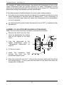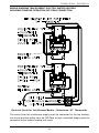
1
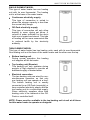
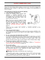
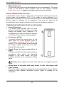
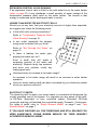
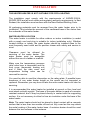
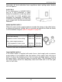
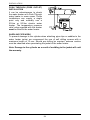
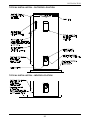
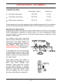
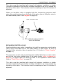
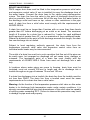
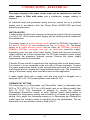
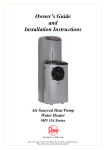
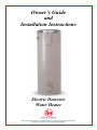
Owner’s Guide and Installation Instructions Electric Domestic Water Heater This water heater must be installed and serviced by an authorised person. Please leave this guide with the householder. Notice to Victorian Customers from the Victorian Plumbing Industry Commission. This water heater must be installed by a licensed person as required by the Victorian Building Act 1993. Only a licensed person will give you a Compliance Certificate, showing that the work complies with all the relevant Standards. Only a licensed person will have insurance protecting their workmanship for 6 years. Make sure you use a licensed person to install this water heater and ask for your Compliance Certificate. PATENTS This water heater may be protected by one or more patents or registered designs in the name of Rheem Australia Pty Ltd. ® TRADEMARKS Registered trademark of Rheem Australia Pty Ltd. TM Trademark of Rheem Australia Pty Ltd. Note: Every care has been taken to ensure the accuracy in preparation of this publication. No liability can be accepted for any consequences, which may arise as a result of its application. CONTENTS HOUSEHOLDER - We recommend you read pages 4 to 17. The other pages are intended for the installer but may be of interest About Your Water Heater ............................................................ 4 Regular Care ................................................................................ 9 Water Supplies ........................................................................... 11 Save A Service Call ................................................................... 15 Installation .................................................................................. 18 Connections – Plumbing .......................................................... 27 Connections – Electrical ........................................................... 31 Commissioning .......................................................................... 34 Draining The Water Heater ....................................................... 37 Warranty ..................................................................................... 39 3 ABOUT YOUR WATER HEATER MODEL TYPE The Rheem® water heater you have chosen will be either a Rheemglas®, Optima™ or RheemPlus™ model. The Optima model has a temperature adjusting knob on the lower front of the water heater. Rheemglas and Optima models are available with either a single heating unit or with twin heating units and the RheemPlus models are available with a single heating unit only (refer to “Single Element Model” on page 7 and “Twin Element Model” on page 7). The water heater can be installed indoor or outdoor. Optima models have an extended warranty (refer to the warranty on page 40). Water is stored in a vitreous enamel lined steel cylinder and heated by the electric immersion heating unit. The thermostat controls the temperature. Automatic safety controls are fitted to the water heater to provide safe and efficient operation. MAINS PRESSURE The water heater is designed to operate at mains pressure by connecting directly to the mains water supply. If the mains supply pressure in your area exceeds that shown on page 19, a pressure limiting valve must be fitted. The supply pressure should be greater than 350 kPa for true mains pressure operation to be achieved. HOW HOT SHOULD THE WATER BE? The water heater features an adjustable thermostat, which allows you to choose the most suitable temperature for your hot water needs. Refer to “Temperature Adjustment” on page 5. A RheemPlus water heater is temperature limited to deliver water not exceeding 50°C. To meet the requirements of the National Plumbing Standard the temperature of the stored water must not be below 60°C. If this water heater is installed as part of a solar water heating system, we recommend the thermostat is set at 60°C to maximise solar contribution. 4 maximum thermostat setting Optima and 050 models maximum thermostat setting Rheemglas and RheemPlus (025, 080 to 400 models) minimum thermostat setting and minimum recommended stored water temperature. top heating unit thermostat setting on a twin element model (not adjustable) RheemPlus maximum delivery temperature. maximum recommended supply temperature to bathrooms and ensuites ABOUT YOUR WATER HEATER HOTTER WATER INCREASES THE RISK OF SCALD INJURY This water heater can deliver water at temperatures which can cause scalding. Check the water temperature before use, such as when entering a shower or filling a bath or basin, to ensure it is suitable for the application and will not cause scald injury. We recommend and it may also be required by regulations that an approved temperature limiting device be fitted into the hot water pipe work to the bathroom and ensuite when a Rheemglas or Optima water heater is installed. This will keep the water temperature below 50°C at the bathroom and ensuite. The risk of scald injury will be reduced and still allow hotter water to the kitchen and laundry. A RheemPlus water heater will not deliver temperatures exceeding 50°C, in accordance with AS 3498. There is no statutory requirement to fit a temperature limiting device if this water heater is installed in other than an early childhood centre, school, nursing home or a facility for young, aged, sick or disabled people. THERMOSTAT The thermostat automatically controls the electricity supply to the heating unit so a constant temperature is maintained. The thermostat and its protective over temperature cut out is mounted inside the front cover of the water heater. There is no need to switch the water heater off when it is not in use, except when you are on an extended holiday. The thermostat is fully automatic and power is only used when heating is required. TEMPERATURE ADJUSTMENT An Optima water heater features a user adjustable thermostat, which allows you to choose the most suitable temperature for your hot water needs. To adjust the temperature, push in the child resistant knob and turn anticlockwise to decrease or clockwise to increase the temperature setting. The Optima has a minimum temperature setting of 60°C and a maximum temperature setting of 75°C. A Rheemglas or RheemPlus water heater features a tradesperson adjustable thermostat. This requires a licensed tradesperson to make any temperature adjustments. The thermostat has a maximum temperature setting of 70°C (75°C for 050 models) and a minimum temperature setting is 60°C. We advise you have your electrician adjust the thermostat to the lowest temperature setting that meets your needs, especially if there are young children or elderly people in your home. Refer to “Hotter Water Increases The Risk of Scald Injury” on page 5. 5 ABOUT YOUR WATER HEATER A RheemPlus water heater is temperature limited to 50°C at the hot water outlet. Increasing the thermostat setting will not increase the outlet temperature but will provide more hot water capacity. WARNING This water heater is only intended to be operated by persons who have the experience or the knowledge and the capabilities to do so. This water heater is not intended to be operated by persons with reduced physical, sensory or mental capabilities i.e. the infirm, or by children. Children should be supervised to ensure they do not interfere with the water heater. This water heater uses 240 V AC power for the electrically operated components. The removal of the front cover(s) will expose 240 V wiring. It must only be removed by an authorised or qualified person. Take care not to touch the power plug on a water heater fitted with a power supply cord and plug with wet hands. SAFETY This water heater is supplied with a thermostat, an over-temperature cut-out, and a combination temperature pressure relief valve. In addition, a RheemPlus water heater has a temperature limiting valve. These devices must not be tampered with or removed. The water heater must not be operated unless each of these devices is fitted and is in working order. The operation of the over-temperature cut-out on the thermostat indicates a possibly dangerous situation. If the over-temperature cut-out operates, it must not be reset and the water heater must be serviced by an authorised or qualified person. If the power supply cord, plug or electrical conduit to the water heater is damaged, it must be replaced by an authorised person in order to avoid a hazard. The power supply cord and plug must be replaced with a genuine replacement part available from Rheem. Phone Rheem Service or their nearest Accredited Service Agent to arrange for an inspection. Warning: For continued safety of this water heater it must be installed, operated and maintained in accordance with the Owner‟s Guide and Installation Instructions. The warranty can become void if relief valves or other safety devices are tampered with or if the installation is not in accordance with these instructions. 6 ABOUT YOUR WATER HEATER SINGLE ELEMENT MODEL This type of water heater has one heating unit with its own thermostat. The heating unit is at the base of the water heater. Continuous electricity supply This type of connection is suited to where the storage capacity is less than the normal daily usage. Off-Peak electricity supply This type of connection will only allow heating to occur during set hours. A volume of water sufficient for the day‟s total use is heated and stored. This type of heating will be more economical due to reduced tariffs by the electricity authority. TWIN ELEMENT MODEL This type of water heater has two heating units, each with its own thermostat. One heating unit is at the base of the water heater and the other near the top. Bottom heating unit During normal operation this heating unit supplies all the hot water. Top heating unit (Booster) This heating unit only operates during periods of high demand to provide an additional supply of heated water. Electrical connection The two heating units are wired for nonsimultaneous operation, so that only one heating unit can operate at a time. The bottom heating unit is usually connected to an Off-Peak (overnight) or time controlled electricity supply and the top heating unit to a continuous supply. Some electricity suppliers allow both heating units to be metered at the OffPeak or controlled tariff. NOTE: Power must be available to the top heating unit circuit at all times for this water heater to operate as designed. 7 ABOUT YOUR WATER HEATER TO TURN OFF THE WATER HEATER If you plan to be away from home for only a few nights, we suggest you leave the water heater switched on. If it is necessary to turn off the water heater: Switch off the electrical supply at the isolating switch to the water heater. Unplug the power supply cord from the power outlet (power supply cord model only). Close the cold water isolation valve at the inlet to the water heater. TO TURN ON THE WATER HEATER Open the cold water isolation valve fully on the cold water line to the water heater. Plug in the power supply cord at the power outlet (power supply cord model only). Switch on the electrical supply at the isolating switch to the water heater. GOING ON HOLIDAY? If you plan to be away from home for one or two nights, we suggest you leave the water heater switched on. However, if you plan to stay away more than a few nights, conserve energy by switching the water heater off at either the switchboard or isolating switch. HOW DO I KNOW IF THE WATER HEATER IS INSTALLED CORRECTLY? Installation requirements are shown on pages 18 to 25. The water heater must be installed by an authorised person and the installation must comply with National Standards AS/NZS 3500.4, AS/NZS 3000 and all local codes and regulatory authority requirements. In New Zealand the installation must conform with the New Zealand Building Code. DOES THE WATER CHEMISTRY AFFECT THE WATER HEATER? The water heater is suitable for most public water supplies, however some water chemistries may have detrimental effects on the cylinder and fittings. If you are in a known harsh water area you must read page 11. If you are not sure, have your water chemistry checked against the conditions described on page 11. HOW LONG WILL THE WATER HEATER LAST? There are a number of factors that will affect the length of service the water heater will provide. These include the water chemistry, the water pressure, the water temperature (inlet and outlet) and the water usage pattern. However, your water heater is supported by a comprehensive warranty (refer to page 40). 8 REGULAR CARE TEMPERATURE PRESSURE RELIEF VALVE This valve is near the top of the water heater and is essential for its safe operation. It is possible for the valve to release a little water through the drain line during each heating period. This occurs as the water is heated and expands by approximately 1/50 of its volume. Continuous leakage of water from the valve and its drain line may indicate a problem with the water heater (refer to “Temperature Pressure Relief Valve Running” on page 16). Warning: Never block the outlet of this valve or its drain line for any reason. Operate the easing lever on the temperature pressure relief valve once every six months. It is very important you raise and lower the lever gently. water heater DANGER: Failure to do this may result in the water heater cylinder failing, or under certain circumstances, exploding. If water does not flow freely from the drain line when the lever is lifted, then the water heater should be checked by Rheem Service or their nearest Accredited Service Agent. lift until water flows from the drain line – lower gently drain line The temperature pressure relief valve should be checked for performance or replaced at intervals not exceeding 5 years, or more frequently in areas where there is a high incidence of water deposits (refer to “Water Supplies” on page 11). 9 REGULAR CARE TEMPERATURE LIMITING VALVE A RheemPlus water heater is fitted with a temperature limiting valve at the hot water outlet. The valve is set to deliver water not exceeding 50°C. The valve should be checked for performance every twelve months. This can be performed by measuring the water temperature from a hot tap with a thermometer. If the water is being delivered at a temperature exceeding 50°C, phone Rheem Service or their nearest Accredited Service Agent to arrange for an inspection. The valve should be replaced at intervals not exceeding 5 years, or more frequently in areas where there is a high incidence of water deposits (refer to “Water Supplies” on page 11). Failure to do this may result in water at a temperature up to 70°C being delivered at the hot tap, increasing the risk of scald injury. EXPANSION CONTROL VALVE In many areas, including South Australia, Western Australia and scaling water areas, an expansion control valve is fitted to the cold water line to the water heater. The expansion control valve may discharge a small quantity of water from its drain line during the heating period instead of the temperature pressure relief valve on the water heater. Operate the easing lever on the expansion control valve once every six months. It is very important you raise and lower the lever gently. The expansion control valve should be checked for performance or replaced at intervals not exceeding 5 years, or more frequently in areas where there is a high incidence of water deposits. 10 WATER SUPPLIES This water heater must be installed in accordance with this advice to be covered by the warranty. This water heater is manufactured to suit the water conditions of most public reticulated water supplies. However, there are some known water chemistries which can have detrimental effects on the water heater and its operation and / or life expectancy. If you are unsure of your water chemistry, you may be able to obtain information from your local water supply authority. This water heater should only be connected to a water supply which complies with these guidelines for the water heater warranty to apply. ANODE The vitreous enamel lined cylinder of the water heater is only covered by warranty when the total dissolved solids (TDS) content in the water is less than 2500 mg/L and when the correct colour coded anode is installed. The use of an incorrect colour coded anode will void the cylinder warranty and may shorten the life of the water heater cylinder. The correct colour coded anode must be selected and fitted to the water heater in accordance with the following advice and the Anode Selection chart on page 12 for warranty to apply to the water heater cylinder. Total Dissolved Solids Anode colour code 0 – 40 mg/L Green 40 – 150 mg/L Green or Black 150 – 400 mg/L Black 400 – 600 mg/L Black or Blue 600 – 2500 mg/L Blue 2500 mg/L + Blue (no cylinder warranty) The changing of anodes must be carried out by a plumber or authorised service person. Note: Some water analysis reports may state the conductivity of the water rather than the level of total dissolved solids. Conductivity, measured in microsiemens per centimetre (µS / cm), is directly proportional to the TDS content of the water. TDS, in mg / L, is approximately 70% of the conductivity in µS / cm. 11 WATER SUPPLIES TOTAL DISSOLVED SOLIDS & CONDUCTIVITY (vitreous enamel lined water heater cylinder) no warranty applies warranty applies to a vitreous enamel lined water heater cylinder if the correct coloured anode is used for the TDS / conductivity level of water 0 40 150 600 Black Green 0 60 400 215 570 TOTAL DISSOLVED SOLIDS (TDS) - mg/L 2500 Blue 860 CONDUCTIVITY - µS/cm to a vitreous enamel lined water heater cylinder Blue 3570 ANODE SELECTION ANODE INSPECTION The anode installed in your water heater will slowly dissipate whilst protecting the cylinder. The life of the water heater cylinder may be extended by arranging for an authorised person to inspect the anode and replace if required. The suggested time after installation when the anode should be inspected is: Rheemglas RheemPlus Optima 8 years 8 years 10 years For water supplies which are either softened, desalinated or where the water supply may alternate between a water tank and a reticulated public supply or another supply, it is recommended the anode be inspected 3 years earlier than shown (refer to “Anode” on page 11). CAUTION If the water supply has a TDS greater than 150 mg/L and a green anode has not been changed to a black anode, or if the TDS is greater than 600 mg/L and the anode has not been changed to a blue anode, there is the possibility the anode may become overactive and hydrogen gas could accumulate in the top of the water heater during long periods of no use. If, under these conditions, the water heater has not been used for two or more weeks the following procedure should be carried out before using any electrical appliances (automatic washing machines and dishwashers) which are connected to the hot water supply. The hydrogen, which is highly flammable, should be vented safely by opening a hot tap and allowing the water to flow. There should be no smoking or naked flame near the tap whilst it is turned on. Any hydrogen gas will be dissipated. This is indicated by an unusual spurting of the water from the tap. Once the water runs freely, any hydrogen in the system will have been released. 12 WATER SUPPLIES SATURATION INDEX The saturation index is used as a measure of the water‟s corrosive or scaling properties. In a corrosive water supply, the water can attack copper parts and cause them to fail. Where the saturation index is less than –1.0, the water is very corrosive and warranty does not apply to a copper sheathed heating unit. A corrosion resistant heating unit must be used for warranty to apply to the heating unit. In a scaling water supply calcium carbonate is deposited out of the water onto any hot metallic surface. Where the saturation index exceeds +0.40, the water is very scaling. An expansion control valve must be fitted on the cold water line after the non-return valve to protect and for warranty to apply to the temperature pressure relief valve and water heater cylinder. Where the saturation index exceeds +0.80, warranty does not apply to a standard watts density heating unit. A low watts density heating unit must be used for warranty to apply to the heating unit. Water which is scaling may be treated with a water softening device to reduce the saturation index of the water. Refer to the Saturation Index chart on page 13. Refer to the cold water connection detail on page 27 for the position of the expansion control valve. Contact Rheem Service or their nearest Accredited Service Agent if a replacement heating unit is required. WITHIN WARRANTY SPECIFICATION -1.0 very corrosive 0 +0.4 no warranty applies to a: -standard watts density heating unit no warranty applies to a: temperature pressure relief valve or a water heater cylinder unless an expansion control valve is fitted. no warranty applies to a: -copper sheathed heating unit SATURATION INDEX (SI) ELECTRIC WATER HEATERS +0.8 SATURATION INDEX (calculated @ 80°C water temperature) scaling very scaling corrosive 13 WATER SUPPLIES CHANGE OF WATER SUPPLY The changing or alternating from one water supply to another can have a detrimental effect on the operation and / or life expectation of a water heater cylinder, a temperature pressure relief valve and a heating unit. Where there is a changeover from one water supply to another, e.g. a rainwater tank supply, bore water supply, desalinated water supply, public reticulated water supply or water brought in from another supply, then water chemistry information should be sought from the supplier or it should be tested to ensure the water supply meets the requirements given in these guidelines for warranty to apply. SUMMARY OF WATER CHEMISTRY ADVICE AFFECTING WARRANTY The warranty of this water heater does not apply on the components listed below if the water heater is connected at any time to a water supply with water chemistry of: Water Chemistry Component Total Dissolved Solids (TDS) > 2500 mg/L water heater cylinder Total Dissolved Solids (TDS) not suitable for anode type water heater cylinder Saturation Index (SI) < -1.0 copper sheathed heating unit Saturation Index (SI) > +0.4 (if expansion control valve is not fitted) water heater cylinder temperature pressure relief valve Saturation Index (SI) > +0.8 standard watts density heating unit 14 SAVE A SERVICE CALL Check the items below before making a service call. You will be charged for attending to any condition or fault that is not related to the manufacture or failure of a part. NOT ENOUGH HOT WATER (OR NO HOT WATER) Is the electricity switched on? Inspect the isolating switch marked “HOT WATER” or “WATER HEATER” at the switchboard and the isolating switch (if one is installed) near the water heater and ensure they are turned on. Note: Check the electricity supply to which the water heater is connected. If on an OffPeak or time controlled electricity supply, remember heating hours are restricted (refer to “Off-Peak Electricity Supply” on page 7). Check the fuse marked “HOT WATER” or “WATER HEATER” at the switchboard. Twin element water heaters A twin element non-simultaneous model must have power available to the top heating unit circuit at all times for the water heater to operate as designed. Are you using more hot water than you think? Is one outlet (especially the shower) using more hot water than you think? Very often it is not realised the amount of hot water used, particularly when showering. Carefully review the family‟s hot water usage. Have your plumber fit a flow control valve to each shower outlet to reduce water usage. Temperature pressure relief valve running Is the relief valve discharging too much water? (Refer to “Temperature Pressure Relief Valve Running” on page 16). Thermostat setting Ensure the thermostat setting is appropriate. You may choose (Optima model) or have your electrician (Rheemglas and RheemPlus model) adjust the thermostat upwards to gain additional hot water capacity. Refer to “Temperature Adjustment” on page 5. Warning: Hotter water increases the risk of scald injury. A RheemPlus water heater is temperature limited to 50°C at the hot water outlet. Increasing the thermostat setting will not increase the outlet temperature but will provide more hot water capacity. 15 SAVE A SERVICE CALL Water heater size Do you have the correct size water heater for your requirements? The sizing guide in the Rheem sales literature and on the Rheem website (www.rheem.com.au) suggests average sizes that may be needed. WATER TEMPERATURE TOO HIGH A RheemPlus water heater is fitted with a temperature limiting valve set to deliver water not exceeding 50°C. If the water is being delivered at a temperature exceeding 50°C, phone Rheem Service or their nearest Accredited Service Agent to arrange for an inspection. Care must be taken by all householders when using hot water until the valve is serviced or replaced. TEMPERATURE PRESSURE RELIEF VALVE RUNNING Normal Operation It is normal and desirable that this valve allows a small quantity of water to escape during the heating cycle. However, if it discharges more than a bucket full of water in 24 hours, there may be another problem. Continuous dribble Try gently raising the easing lever on the relief valve for a few seconds (refer to “Temperature Pressure Relief Valve” on page 9). This may dislodge a small particle of foreign matter and clear the fault. Release the lever gently. Steady flows for long period (often at night) This may indicate the mains water pressure sometimes rises above the designed pressure of the water heater. Ask your installing plumber to fit a pressure limiting valve. Warning: Never replace the relief valve with one of a higher pressure rating. Heavy flows of hot water until water heater is cold - then stops until water reheats The water heater must be switched off at the switchboard. Phone Rheem Service or their nearest Accredited Service Agent to arrange for an inspection. 16 SAVE A SERVICE CALL EXPANSION CONTROL VALVE RUNNING If an expansion control valve is fitted in the cold water line to the water heater (refer to page 27) it may discharge a small quantity of water instead of the temperature pressure relief valve on the water heater. The benefit is that energy is conserved as the discharged water is cooler. HIGHER THAN EXPECTED ELECTRICITY BILLS Should you at any time, feel your electricity account is higher than expected, we suggest you check the following points: Is the relief valve running excessively? Refer to “Temperature Pressure Relief Valve Running” on page 16. Is one outlet (especially the shower) using more hot water than you think? Refer to “Not Enough Hot Water” on page 15. Is there a leaking hot water pipe, dripping hot water tap, etc? Even a small leak will waste a surprising quantity of hot water and electricity. Replace faulty tap washers, and have your plumber rectify any leaking pipe work. Has there been an increase in hot water usage? An increase in hot water usage will result in an increase in water heater operation. Has your water heating tariff rate been increased by your electricity retailer since your previous account? ELECTRICITY TARIFFS The electricity tariff to which your water heater is connected will determine the overall operating cost of the system. It is important you are aware of this tariff, i.e. Off-Peak (overnight) or time controlled supply, Extended Off-Peak (overnight and day) or Extended time controlled supply, Domestic / Continuous. For types of tariffs, refer to “Single Element Model” on page 7 and “Twin Element Model” on page 7. IF YOU HAVE CHECKED ALL THE FOREGOING AND STILL BELIEVE YOU NEED ASSISTANCE, PHONE RHEEM SERVICE OR THEIR NEAREST ACCREDITED SERVICE AGENT. 17 INSTALLATION THIS WATER HEATER IS NOT SUITABLE FOR POOL HEATING The installation must comply with the requirements of AS/NZS 3500.4, AS/NZS 3000 and all local codes and regulatory authority requirements. In New Zealand, the installation must conform with the New Zealand Building Code. All packaging materials must be removed from the water heater prior to its installation. This includes the removal of the cardboard base of the carton from the underside of the water heater. WATER HEATER LOCATION This water heater is suitable for either outdoor or indoor installation (a model with a supply cord and plug is suitable for indoor installation only). Whether located outdoor or indoor, the water heater should be installed close to the most frequently used outlet and its position chosen with safety and service in mind. Clearance must be allowed for servicing of the water heater. The water heater must be accessible without the use of a ladder or scaffold. Make sure the temperature pressure relief valve lever is accessible and the front cover, thermostat, heating unit and if fitted, the side cover and temperature limiting valve can be removed for service. You must be able to read the information on the rating plate. If possible leave headroom of one water heater height so the anode can be inspected or replaced. Remember you may have to take the entire water heater out later for servicing. It is recommended the water heater be installed at ground or floor level and must stand vertically upright. The base of the water heater is made of corrosion resistant material, and it may be placed directly in contact with the supporting surface. It is not necessary to allow for free air circulation under the base of the water heater. Note: The water heater should not be placed in direct contact with a concrete surface that is less than two months old and not fully cured as this may attack the metal coating of the water heater base. A moisture barrier should be used between the two surfaces in this instance. 18 INSTALLATION Remember all local authorities have regulations about putting water heaters into roof spaces. SAFE TRAY It is a requirement of AS/NZS 3500.4 that for a new installation, a water heater be installed in a safe tray where in the event of a leak, property may otherwise be damaged. Construction, installation and draining of a safe tray must comply with the abovementioned Standard. MAINS WATER SUPPLY Where the mains water supply pressure exceeds that shown in the table below, an approved pressure limiting valve is required and should be fitted as shown in the installation diagram (refer to diagram on page 27). Model 025 to 160 250 to 400 Relief valve setting 1400 kPa 1000 kPa Expansion control valve setting* 1200 kPa 850 kPa With expansion control valve 950 kPa 650 kPa Without expansion control valve 1120 kPa 800 kPa Max. mains supply pressure * Expansion control valve not supplied with water heater TANK WATER SUPPLY If the water heater is supplied with water from a tank supply and a pressure pump system is not installed, then the bottom of the supply tank must be at least 1 m above the highest point of the hot water plumbing system, including the water heater. Care must be taken to avoid air locks. The cold water line to the water heater should be adequately sized and fitted with a full flow gate valve or ball valve. 19 INSTALLATION HOT WATER DELIVERY This water heater can deliver water at temperatures which can cause scalding. It is necessary and we recommend that a temperature limiting device be fitted between a Rheemglas or Optima water heater and the hot water outlets in any ablution area such as a bathroom or ensuite, to reduce the risk of scalding. The installing plumber may have a legal obligation to ensure the installation of this water heater meets the delivery water temperature requirements of AS/NZS 3500.4 so that scalding water temperatures are not delivered to a bathroom, ensuite or other ablution area. Where a temperature limiting device is installed adjacent to the water heater, the cold water line to the temperature limiting device can be branched off the cold water line either before or after the isolation valve, pressure limiting valve and non return valve to the water heater. If an expansion control valve is required, it must always be installed after the non return valve and be the last valve prior to the water heater. If a pressure limiting valve is installed on the cold water line to the water heater and the cold water line to a temperature limiting device branches off before this valve or from another cold water line in the premises, then a pressure limiting valve of an equal pressure setting may be required prior to the temperature limiting device. Two Temperature Zones Using a Temperature Limiting Device LEGEND 20 INSTALLATION A RheemPlus water heater will not deliver temperatures exceeding 50°C, in accordance with AS 3498. There is no statutory requirement to fit a temperature limiting device if this water heater is installed in other than an early childhood centre, school, nursing home or a facility for young, aged, sick or disabled people. CIRCULATED HOT WATER FLOW AND RETURN SYSTEM A RheemPlus water heater cannot be installed as part of a circulated hot water flow and return system in a building. If a Rheem water heater is to be installed as part of a circulated hot water flow and return system, a storage water heater able to provide a hot water outlet temperature of at least 60°C must be used. Note: The thermostat must always be set to at least 60°C. Refer to the diagram on page 22. Temperature Limiting Device A temperature limiting device cannot be installed in circulated hot water flow and return pipe work. The tempered water from a temperature limiting device cannot be circulated. Where a circulated hot water flow and return system is required in a building, a temperature limiting device can only be installed on a dead leg, branching off the circulated hot water flow and return pipe. If circulated tempered water were to be returned back to the water heater, depending on the location of the return line connection on the water supply line to the water heater, then either: water will be supplied to the cold water inlet of the temperature limiting device at a temperature exceeding the maximum recommended water supply temperature, or when the hot taps are closed no water will be supplied to the cold water inlet of the temperature limiting device whilst hot water will continue to be supplied to the hot water inlet of the temperature limiting device. These conditions may result in either water at a temperature exceeding the requirements of AS/NZS 3500.4 being delivered to the hot water outlets in the ablution areas, or the device closing completely and not delivering water at all, or the device failing. Under either condition, the operation and performance of the device cannot be guaranteed. 21 INSTALLATION Circulated Hot Water Flow and Return Continuous Electric Water Heater Off-Peak or Time Controlled Electricity Supply A single or twin element electric water heater connected to an Off-Peak LEGEND should not be installed as part of a circulated hot water flow electricity supply and return system in a building. The benefits of the Off-Peak electricity supply will be significantly reduced. If a circulated flow and return system is required, it is necessary to bypass the Off-Peak electric water heater and install a secondary water heater connected to the hot water flow and return line and supplied from the Off-Peak electric water heater. Refer to the diagram on page 22. Circulated Hot Water Flow and Return System Off-Peak Electric Water Heater LEGEND 22 INSTALLATION REDUCING HEAT LOSSES The cold water line to and the hot water line from the water heater must be insulated in accordance with the requirements of AS/NZS 3500.4. The insulation must be weatherproof and UV resistant if exposed. ANODE The vitreous enamel lined cylinder of the water heater is only covered by warranty when the total dissolved solids (TDS) content in the water is less than 2500 mg/L and when the correct colour coded anode is installed. The use of an incorrect colour coded anode will void the cylinder warranty and may shorten the life of the water heater cylinder. The correct colour coded anode for the water supply being used must be selected and fitted to the water heater for warranty to apply to the water heater cylinder (refer to “Water Supplies” on page 11 and the Anode Selection chart on page 12). The black anode is typically fitted as standard. Total Dissolved Solids Anode colour code 0 – 40 mg/L Green 40 – 150 mg/L Green or Black 150 – 400 mg/L Black 400 – 600 mg/L Black or Blue 600 – 2500 mg/L Blue 2500 mg/L + Blue (no cylinder warranty) If the water supply has a TDS greater than 150 mg/L and a green anode has not been changed to a black anode, or if the TDS is greater than 600 mg/L and the anode has not been changed to a blue anode, there is the possibility the anode may become overactive and hydrogen gas could accumulate in the top of the water heater during long periods of no use. In areas where this is likely to occur, the installer should instruct the householder on how to dissipate the gas safely (refer to “Caution” on page 12). 23 INSTALLATION PUSH THROUGH (FREE OUTLET) INSTALLATION It can be advantageous to plumb the water heater as a Push Through water heater in some cases. These installations can supply a single point only and normally use a 25 litre or 50 litre electric water heater. The temperature pressure relief valve supplied with this heater must be fitted to the water heater. SADDLING PIPE WORK To prevent damage to the cylinder when attaching pipe clips or saddles to the water heater jacket, we recommend the use of self drilling screws with a maximum length of 13 mm. Should pre drilling be required, extreme caution must be observed when penetrating the jacket of the water heater. Note: Damage to the cylinder as a result of saddling to the jacket will void the warranty. 24 INSTALLATION TYPICAL INSTALLATION – OUTDOOR LOCATION OUTDOOR LOCATIONS TYPICAL INSTALLATION – INDOOR LOCATION OUTDOOR LOCATIONS INDOOR LOCATIONS INDOOR LOCATIONS 25 INSTALLATION DIMENSIONS AND TECHNICAL DATA Rheemglas and Optima Rheemglas Single Element Rheemglas Twin Element Optima Single Element Optima Twin Element RheemPlus Single Element RheemPlus 111 025 191 050 111 080 111 125 111 160 111 250 111 315 162 160 162 250 162 315 411 250 411 315 462 250 462 315 121 125 121 160 121 250 121 315 111 400 162 400 411 400 462 400 - Hot Water Delivery Litres 18 50 80 125 160 250 315 Boost Capacity Litres - - - - 45 50 50 90 A mm 390 695 940 1340 1610 1395 1640 1840 690 Dimensions Approx. Weight empty 400 B mm 385 393 480 480 480 640 640 C mm 420 429 515 515 515 700 700 755 D mm 130 397 702 1102 1332 1117 1317 1479 E mm 116 142 64 64 104 73 113 121 F mm 75 80 84 84 84 128 128 129 G mm - - - - 1085 1005 1255 1346 H deg 26 26 23 23 23 32 32 30 J deg 65 59 58 58 58 88 88 83 K mm - - - 545 545 705 705 - L mm - - - 183 183 262 262 - kg 18 29 35 49 57 74 99 118 111, 411, 162, 462 and 121 models have left hand connections. 191 models have left and right hand connections and are available in 050 litre delivery capacity only. Rheemglas single element models with right hand connections only are available in 80 and 125 litre delivery capacities and have a 171 prefix. Technical data is subject to change. 26 CONNECTIONS – PLUMBING CONNECTION SIZES Rheemglas, Optima RheemPlus Hot water connection: RP ¾/20 G¾B Cold water connection: RP ¾/20 G¾B Relief valve connection: RP ½/15 RP ½/15 All plumbing work must be carried out by a qualified person and in accordance with the Plumbing Standard AS/NZS 3500.4 and local authority requirements. WATER INLET AND OUTLET All pipe work must be cleared of foreign matter before connection and purged before attempting to operate the water heater. All olive compression fittings must use brass or copper olives. Use thread sealing tape or approved thread sealant on all fittings. An isolation valve and non-return valve must be installed on the cold water line to the water heater. An acceptable arrangement is shown in the diagram. Refer also to “Hot Water Delivery” on page 20 and to “Mains Water Supply” on page 19. A disconnection union must always be provided at the cold water inlet and hot water outlet on the water heater to allow for disconnection of the water heater. This water heater has either a plastic dip tube or fitting liner in the inlet and outlet fittings (see diagram). These must be in place for the water heater to function properly. Do not remove or damage them by using heat nearby. They will be pushed into the correct position as the fitting is screwed in. 27 CONNECTIONS – PLUMBING LEFT AND RIGHT HAND SIDE WATER CONNECTIONS The cold water supply, hot water supply and temperature pressure relief valve can be connected to either side of a water heater with both left and right hand side water connections. A kit is supplied with the water heater to plug off the unused cold, hot and temperature pressure relief valve fittings. The kit contains: Model 050 2 x ¾” brass plugs 1 x ½” brass plug 2 x large plastic insulation caps 1 x small plastic insulation cap Plugging Off Unused Connections – 050 model Apply approved sealing tape or compound to the thread of each plug. Fit a ¾” plug to each of the unused cold water and hot water fittings and the ½” plug to the unused TPR valve fitting. Tighten the plugs. Fit a plastic insulation cap over each plug. PIPE SIZES To achieve true mains pressure operation, the cold water line to the water heater should be the same size or bigger than the hot water line from the water heater. The pipe sizing for hot water supply systems should be carried out by persons competent to do so, choosing the most suitable pipe size for each individual application. Reference to the technical specifications of the water heater and local regulatory authority requirements must be made. TEMPERATURE PRESSURE RELIEF VALVE The temperature pressure relief valve is shipped either under the top flap of the water heater carton or behind the front cover or in a plastic bag attached to the water heater. The temperature pressure relief valve must be fitted before the water heater is operated. Before fitting the relief valve, make sure the probe has not been bent. Seal the thread with Teflon tape - never hemp. Make sure the tape does not hang over the end of the thread. Screw the valve into the correct opening (refer to the installation diagram page 25) leaving the valve outlet pointing downwards. Do not use a wrench the valve body - use the spanner flats provided. A copper drain line must fitted to the temperature pressure relief valve (refer to "Relief Valve Drain" page 30). 28 on on be on CONNECTIONS – PLUMBING The valve must be insulated with closed cell polymer insulation or similar (minimum thickness 9 mm) and the insulation installed so as not to impede the operation of the valve. The insulation must be weatherproof and UV resistant if exposed. Where an insulation collar is supplied with the temperature pressure relief valve, this must be placed over the body of the valve, prior to fitting the valve to the water heater (refer to the diagram on page 29). USE TEFLON TAPE This model wate with dual handed A kit is supplied fittings. The kit c parts: 2 x R ¾ /20 bras 1 x R ½ /15 bras 2 x large plastic 1 x small plastic FIT SUPPLIED INSULATION TO VALVE AS SHOWN Plugging Off Unu Apply approved compound to the 1. Fit a ¾” plug t EXPANSION CONTROL VALVE cold water and h Local regulations may make it mandatory to install an expansion control½” valve plug to the un (ECV) in the cold water line to the water heater. In other areas, an ECV is the plug Tighten required if the saturation index is greater than +0.4 (refer to “Water Supplies” on page 11). FITTING OF RELIEF VALVE 2. Fit a plastic in THE TEMPERATURE PRESSURE RELIEF VALVE MUST plug. FITTED TOmust THE WATER AS SHOWN The expansion BE control valve always HEATER be installed after theABOVE. non return valve and be the last valve installed prior to the water heater (refer to diagram on page 27). A copper drain line must be fitted to the expansion control valve (refer to "Relief Valve Drain" on page 30). The valve must be insulated with closed cell polymer insulation or similar (minimum thickness 9 mm) and the insulation installed so as not to impede the operation of the valve. The insulation must be weatherproof and UV resistant if exposed. 29 CONNECTIONS – PLUMBING RELIEF VALVE DRAIN DN15 copper drain lines must be fitted to the temperature pressure relief valve and expansion control valve (if one is installed) to carry the discharge clear of the water heater. Connect the drain lines to the valves using disconnection unions. The drain line from the valve to the point of discharge should be as short as possible, have a continuous fall all the way from the water heater to the discharge outlet and have no tap, valves or other restrictions in the pipe work. A drain line from a relief valve must comply with the requirements of AS/NZS 3500.4. A drain line must be no longer than 9 metres with no more than three bends greater than 45° before discharging at an outlet or air break. The maximum length of 9 metres for a drain line is reduced by 1 metre for each additional bend required of greater than 45°, up to a maximum of three additional bends. Where the distance to the point of final discharge exceeds this length, the drain line can discharge into a tundish. Subject to local regulatory authority approval, the drain lines from the temperature pressure relief valve and expansion control valve from an individual water heater may be interconnected. The outlet of a drain line must be in such a position that flow out of the pipe can be easily seen, but arranged so discharge will not cause injury, damage or nuisance. The termination point of a drain line must comply with the requirements of AS/NZS 3500.4. Drain lines must not discharge into a safe tray. In locations where water pipes are prone to freezing, drain lines must be insulated, must not exceed 300 mm in length and are to discharge into a tundish through an air gap of between 75 mm and 150 mm. If a drain line discharges into a tundish, the drain line from the tundish must be not less than DN20. The drain line from a tundish must meet the same requirements as for a drain line from a relief valve. Warning: As the function of the temperature pressure relief valve on this water heater is to discharge high temperature water under certain conditions, it is strongly recommended the pipe work downstream of the relief valve be capable of carrying water exceeding 93°C. Failure to observe this precaution may result in damage to pipe work and property. 30 CONNECTIONS – ELECTRICAL The power supply to the water heater must not be switched on until the water heater is filled with water and a satisfactory megger reading is obtained. All electrical work and permanent wiring must be carried out by a qualified person and in accordance with the Wiring Rules AS/NZS 3000 and local authority requirements. WATER HEATER A water heater not fitted with a supply cord and plug must be directly connected to a 240 V AC, 50 Hz mains power supply with an isolating switch installed at the switchboard. The power supply to a twin element model should be Off-Peak (overnight) to the bottom heating unit and continuous to the top heating unit. The power supply to a single element model can be either an Off-Peak (overnight), Extended Off-Peak (overnight and day) or continuous electricity supply, depending upon the size of the water heater. Check with the local electricity supply authority as to their requirements. An Off-Peak (overnight) power supply will provide the maximum financial savings. Discuss the power supply requirements with the householder. A flexible 20 mm conduit is required for the electrical cable to the water heater. The conduit is to be connected to the unit with a 20 mm terminator. Connect the power supply wires directly to the terminal block and earth tab connection, ensuring there are no excess wire loops inside the front cover. The temperature rating of the power supply wires insulation must suit this application. A water heater fitted with a supply cord and plug must be plugged into a switched 240 V AC, 50 Hz mains power outlet rated at 10 A. THERMOSTAT SETTING The thermostat on a Rheemglas and RheemPlus model is adjustable from 60°C to 70°C (60°C to 75°C on a 050 model) and on an Optima model from 60°C to 75°C. The thermostat is adjusted by turning the adjuster (Rheemglas / RheemPlus model) or knob (Optima model) anticlockwise to decrease the temperature setting and clockwise to increase the temperature setting. Only adjust the thermostat setting on a Rheemglas and RheemPlus model when the isolating switch is switched off at the switchboard. The top thermostat on a twin element model is fixed at 60°C. 31 CONNECTIONS – ELECTRICAL For reasons of safety and economy, we advise the thermostat be set at the lowest temperature that will provide sufficient hot water. Dishwasher running costs can be adversely affected if the thermostat is set below 65°C. Discuss the thermostat setting requirements with the householder. If this water heater is installed as part of a solar water heating system: the solar control system must be of a design to limit solar contribution so the water temperature in the tank does not exceed 80°C. This is necessary to ensure the solar input does not cause the thermostat‟s over-temperature cut-out to operate. we recommend the water heater thermostat is set at 60°C to maximise solar contribution. ASSEMBLY OF ADJUSTER MECHANISM ON OPTIMA MODEL When the front cover has been removed, reassemble as follows: Remove the knob from the front cover by depressing the locking tabs on the inside of the front cover. Turn the thermostat to the lowest temperature (refer to “Temperature Adjustment” on page 5). Fit the front cover. Insert the connector shaft through the hole into the thermostat adaptor slots. Align the knob slots over the „T‟ drive on the connector shaft, with the dial at the lowest setting – a firm push with the hand on the knob front face will engage the locking tabs. 32 CONNECTIONS – ELECTRICAL WIRING DIAGRAM TWIN ELEMENT ELECTRIC WATER HEATERS NON-SIMULTANEOUS OPERATION OFF-PEAK CONNECTION Electrical Circuit for Twin Element Models – Robertshaw “ST” Thermostats The active from the continuous supply must be connected to the top heating unit circuit and the active from the Off-Peak or time controlled supply must be connected to the bottom heating unit circuit. 33 COMMISSIONING TO FILL AND TURN ON THE WATER HEATER The power supply to the water heater must not be switched on until the water heater is filled with water and a satisfactory megger reading is obtained. Open all of the hot water taps in the house (don‟t forget the shower). Open the cold water isolation valve fully on the cold water line to the water heater. Air will be forced out of the taps. Close each tap as water flows freely from it. Check the pipe work for leaks. Plug in the power supply cord at the power outlet (power supply cord model only). Switch on the electrical supply at the isolating switch to the water heater. If it is necessary to adjust the outlet temperature of the 384 or 854 RheemPlus model, refer to “Outlet Temperature Compensation Adjustment – RheemPlus” on page 35. Explain to the householder or a responsible officer the functions and operation of the water heater. Upon completion of the installation and commissioning of the water heater, leave this guide with the householder or a responsible officer. TO TURN OFF THE WATER HEATER If it is necessary to turn off the water heater on completion of the installation, such as on a building site or where the premises is vacant, then; Switch off the electrical supply at the isolating switch to the water heater. Unplug the power supply cord from the power outlet (power supply cord model only). Close the cold water isolation valve at the inlet to the water heater. 34 COMMISSIONING OUTLET TEMPERATURE COMPENSATION ADJUSTMENT – RHEEMPLUS The maximum outlet temperature of a RheemPlus water heater may be adjusted to compensate for temperature losses in the pipe work between the water heater outlet and sanitary fixtures. Warning: After adjustment of the temperature limiting valve, the water temperature MUST NOT exceed 50°C from the first tap in the hot water pipe work after the water heater used for personal hygiene purposes, such as in a bathroom or ensuite. To adjust the maximum outlet temperature: Ensure the temperature of the water in the water heater is up to the thermostat setting on the water heater. The temperature of the water can be measured at the temperature pressure relief valve drain discharge point. Do not measure this temperature from a hot tap Operate the easing lever on the temperature pressure relief valve and place the thermometer in the flow of water from the relief valve drain line. Remove the upper plastic casing and insulation covering the pipe work on the side of the water heater, by removing the three (3) retaining screws, to expose the temperature limiting valve. Locate the first hot tap in the hot water pipe work after the water heater used for personal hygiene purposes. Turn on the hot tap fully to achieve maximum flow. RHEEMPLUS CASING REMOVAL Using a thermometer, measure the temperature of the water from the tap, until the temperature stops increasing. If the water temperature is below 50°C the maximum outlet temperature of the water heater can be adjusted upwards. 35 COMMISSIONING Turn the adjusting knob on the temperature limiting valve counter-clockwise (down away from the water heater), using a 6 mm Allen key. Turning the adjusting knob counter clockwise (down away from the water heater) increases the outlet water temperature, turning it clockwise (up towards the water heater) decreases the outlet water temperature. Repeat the water temperature measurement from the same hot tap. RHEEMPLUS TEMPERATURE ADJUSTMENT Further adjust the temperature limiting valve as required, turning the adjusting knob either counter clockwise (down away from the water heater) or clockwise (up towards the water heater) to increase or decrease the outlet water temperature, until an acceptable water temperature not exceeding 50°C is measured at the same hot tap. Turn off the hot tap. Replace the insulation and plastic casing to cover the temperature limiting valve and pipe work on the side of the water heater and secure using the three (3) retaining screws. 36 DRAINING THE WATER HEATER To drain the water heater: Turn off the water heater (refer to “To Turn Off The Water Heater” on page 34). Close all hot water taps. Operate the relief valve release lever - do not let the lever snap back or you will damage the valve seat. Operating the lever will release the pressure in the water heater. Undo the union at the cold water inlet to the water heater and attach a hose to the water heater side of the union. Let the other end of the hose go to a drain. Operate the relief valve again. This will let air into the water heater and allow the water to drain through the hose. 37 This page is intentionally blank. 38 RHEEM ELECTRIC DOMESTIC MAINS PRESSURE WATER HEATER WARRANTY - AUSTRALIA ONLY WARRANTY CONDITIONS 1. This warranty is applicable only to water heaters manufactured from 1st July 2010. 2. The water heater must be installed in accordance with the water heater installation instructions, supplied with the water heater, and in accordance with all relevant statutory and local requirements of the State in which the water heater is installed. 3. Where a failed component or water heater is replaced under warranty, the balance of the original warranty period will remain effective. The replaced component or water heater does not carry a new warranty. 4. Where the water heater is installed outside the boundaries of a metropolitan area as defined by Rheem or further than 25 km from a regional Rheem branch office, or an Accredited Service Agent, the cost of transport, insurance and travelling costs between the nearest Rheem Accredited Service Agent’s premises and the installed site shall be the owner’s responsibility. 5. Where the water heater is installed in a position that does not allow safe, ready access, the cost of accessing the site safely, including the cost of additional materials handling and / or safety equipment, shall be the owner’s responsibility. 6. The warranty only applies to the water heater and original or genuine (company) component replacement parts and therefore does not cover any plumbing or electrical parts supplied by the installer and not an integral part of the water heater, e.g. pressure limiting valve; isolation valves; nonreturn valves; electrical switches; pumps or fuse. 7. The water heater must be sized to supply the hot water demand in accordance with the guidelines in the water heater literature. WARRANTY EXCLUSIONS 1. REPAIR AND REPLACEMENT WORK WILL BE CARRIED OUT AS SET OUT IN THE WATER HEATER WARRANTY, HOWEVER THE FOLLOWING EXCLUSIONS MAY CAUSE THE WATER HEATER WARRANTY TO BECOME VOID AND MAY INCUR A SERVICE CHARGE AND / OR COST OF PARTS. a) Accidental damage to the water heater or any component, including: Acts of God; failure due to misuse; incorrect installation; attempts to repair the water heater other than by a Rheem Accredited Service Agent or Rheem Service. b) Where it is found there is nothing wrong with the water heater; where the complaint is related to excessive discharge from the temperature and / or pressure relief valve due to high water pressure; where there is no flow of hot water due to faulty plumbing; where water leaks are related to plumbing and not the water heater or water heater components; where there is a failure of electricity or water supplies; where the supply of electricity or water does not comply with relevant codes or acts. c) Where the water heater or water heater component has failed directly or indirectly as a result of: excessive water pressure; excessive temperature and / or thermal input; blocked overflow / vent drain; corrosive atmosphere; ice formation in the pipe work to or from the water heater. d) Where the water heater is located in a position that does not comply with the water heater installation instructions or relevant statutory requirements, causing the need for major dismantling or removal of cupboards, doors or walls, or use of special equipment to bring the water heater to floor or ground level or to a serviceable position. e) Where the water heater has been connected at any time to a water supply that does not comply with the water supply guidelines as outlined in the Owner’s Guide and Installation Instructions. 2. SUBJECT TO ANY STATUTORY PROVISIONS TO THE CONTRARY, THIS WARRANTY EXCLUDES ANY AND ALL CLAIMS FOR DAMAGE TO FURNITURE, CARPETS, WALLS, FOUNDATIONS OR ANY OTHER CONSEQUENTIAL LOSS EITHER DIRECTLY OR INDIRECTLY DUE TO LEAKAGE FROM THE WATER HEATER, OR DUE TO LEAKAGE FROM FITTINGS AND / OR PIPE WORK OF METAL, PLASTIC OR OTHER MATERIALS CAUSED BY WATER TEMPERATURE, WORKMANSHIP OR OTHER MODES OF FAILURE. 39 RHEEM ELECTRIC DOMESTIC MAINS PRESSURE WATER HEATER WARRANTY - AUSTRALIA ONLY WARRANTY Rheem will repair or replace, at Rheem’s sole discretion and subject to the warranty conditions and exclusions, any component or the water heater if it fails within the warranty period below. Installation Model Period All Components (from date of installation) Year All installations All models 1 Cylinder (from date of installation) Years Rheemglas 2 & 3 RheemPlus Years Water heater 4&5 installed in a “single-family Years domestic dwelling” 2 to 5 Optima Years 6 to 10 Water heater Rheemglas Years installed in RheemPlus 2 & 3 any other than a Years “single-family Optima 2 to 5 domestic dwelling” Warranty New component or water heater, free of charge, including labour.* New water heater, free of charge, including labour.* New water heater, free of charge, with installation and labour costs being the responsibility of the owner. New water heater, free of charge, including labour.* New water heater, free of charge, with installation and labour costs being the responsibility of the owner. New water heater, free of charge, with installation and labour costs being the responsibility of the owner. New water heater, free of charge, with installation and labour costs being the responsibility of the owner. Note * Refer to items 4 and 5 of warranty conditions. Rheem reserves the right to transfer fully functional components from the defective water heater to the replacement water heater if required. In addition to this warranty, the Trade Practices Act 1974 and similar laws in each state and territory provide the owner under certain circumstances with certain minimum statutory rights in relation to your Rheem water heater. This warranty must be read subject to that legislation and nothing in this warranty has the effect of excluding, restricting or modifying those rights. FOR SERVICE TELEPHONE 131 031 AUSTRALIA 0800 657 335 NEW ZEALAND or refer local Yellow Pages RHEEM AUSTRALIA PTY LTD A.B.N. 21 098 823 511 www.rheem.com.au Revision Date: 2010 July 121996E 40