1
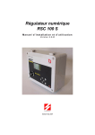
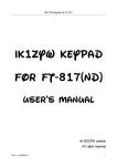
HF/VHF/UHF
ALL MODE TRANSCEIVER
FT-817ND
OPERATING MANUAL
VERTEX STANDARD CO., LTD.
4-8-8 Nakameguro, Meguro-Ku, Tokyo 153-8644, Japan
VERTEX STANDARD
US Headquarters
10900 Walker Street, Cypress, CA 90630, U.S.A.
YAESU EUROPE B.V.
P.O. Box 75525, 1118 ZN Schiphol, The Netherlands
YAESU UK LTD.
Unit 12, Sun Valley Business Park, Winnall Close
Winchester, Hampshire, SO23 0LB, U.K.
VERTEX STANDARD HK LTD.
Unit 5, 20/F., Seaview Centre, 139-141 Hoi Bun Road,
Kwun Tong, Kowloon, Hong Kong
Contents
Introduction .................................................... 1
Specifications .................................................. 2
Accessories & Options ................................... 4
Plug Pinout ...................................................... 5
Installation ...................................................... 6
Connecting the Supplied YHA-63 Antenna ......... 6
Connecting the Microphone ................................. 7
Shoulder Strap Installation ................................... 7
Rubber Foot Installation ....................................... 7
Alkaline Battery Installation and Use .................. 8
External Power Connections ................................ 9
FNB-85 Ni-Cd Battery Pack Installation and Use .. 10
Front Panel Control & Switches ................. 12
Side Panel Switch & Connectors ................ 16
Rear Panel Connectors ................................ 17
Operation ...................................................... 18
Turning the Transceiver On and Off .................. 18
Supply Voltage Display ...................................... 18
Operating Band Selection .................................. 19
Mode Selection ................................................... 19
Adjusting the Audio Volume Level .................... 19
Menu Quick Start ............................................... 20
Adjusting the RF Gain and Squelch ................... 20
Setting the Operating Frequency ........................ 21
Stacked VFO System ......................................... 21
Operation on 5 MHz Band
(U.S. Version Only) ............................................ 22
Receiver Accessories ..................................... 23
Clarifier (Receiver incremental Tuning) ............ 23
IF SHIFT ............................................................ 24
AGC (Automatic Gain Control) ......................... 25
Noise Blanker ..................................................... 25
IPO (Intercept Point Optimization) .................... 25
ATT (Front End Attenuator) ............................... 26
AM/FM DIAL .................................................... 26
Automatic Power-Off Feature ............................ 27
Transmitter Operation ................................. 28
SSB Transmission .............................................. 28
Basic Setup/Operation ................................... 28
Adjusting the transmitter Power Output ... 28
VOX Operation ............................................. 29
CW Transmission ............................................... 30
Operation using Straight Key/
External Keying Device ................................ 30
Operation using
the Built-in Electronic Keyer ........................ 32
FM Transmission ................................................ 33
Basic Setup/Operation ................................... 33
Repeater Operation ........................................ 33
Tone Search Scanning ............................... 35
DCS Operation .............................................. 36
DCS Search Scanning ............................... 36
ARTSTM (Auto Range Transpond System)
Operation ....................................................... 37
CW Identifier Setup ....................................... 37
Digital Mode Operation (SSB-Based AFSK) .... 38
RTTY (Radio TeleType) Operation ............... 38
PSK31 Operation ........................................... 39
“USER” Defined Digital Modes ................... 40
Packet (1200/9600 bps FM) Operation .............. 41
AM Transmission ............................................... 42
Split Frequency Operation ................................. 42
Time-Out Timer .................................................. 43
WeatherFax Monitoring ..................................... 43
Memory Operation ...................................... 44
QMB Channel ..................................................... 44
Memory Operation on
“Regular” Memory Channels ............................. 45
Normal Memory Storage .............................. 45
Split-Frequency Memory Storage ................. 45
Memory Channel Recall ................................ 46
Masking Memory .......................................... 47
Memory Operation on
“HOME” Channel Memories ............................. 48
Labeling Memories ............................................ 49
Spectrum Scope Monitor Operation .......... 50
Smart SearchTM Operation .......................... 51
Scanning Operation ..................................... 52
Scanning Operation ............................................ 52
Scan Skip Programming (Memory Mode Only) .... 52
Scan-Resume Choices .............................. 52
Programmable Memory Scan (PMS) Operation . 54
Dual Watch Operation ................................. 56
Operation on Alaska Emergency Frequency:
5167.5 kHz (U.S. Version Only) ........................ 57
Menu Operation ........................................... 58
Clonning ........................................................ 69
CAT System Programming ....................... 70
Installation of Optional Accessories ........... 74
Option Filters YF-122S/YF-122C ................... 74
High-Stability Reference Oscillator TCXO-9 ... 75
Power-on Microprocessor Reset Procedure ..... 76
Appendix ....................................................... 77
Setup of Memories for Low Earth Orbit (LEO)
FM Satellite Operation ....................................... 77
BAND DATA Format ......................................... 80
INTRODUCTION
The FT-817ND is a compact, innovative multiband, multimode portable transceiver for the
amateur radio MF/HF/VHF/UHF bands. Providing coverage of the 160-10 meter bands
(include the 60 m band: USA version) plus the 6 m, 2 m, and 70 cm bands, the FT-817ND
includes operation on the SSB, CW, AM, FM, and Digital modes, yielding the most comprehensive performance package available for portable operation.
Designed for use either from an external DC power source or internal batteries, the FT817ND provides five watts of power output from a 13.8-Volt external power supply. When
using the FNB-85 Ni-MH Battery Pack or 8 “AA” Alkaline Cells (not supplied), the FT817ND automatically switches to 2.5 Watts of output power. Via the Menu system, “High”
power may be selected during battery operation, providing as much as 5 Watts of output,
depending on the operating frequency.
The multi-function Liquid-Crystal Display includes Blue, Amber, and Violet backlighting,
which may be disabled for battery conservation. The display includes bar-graph indication
of power output, ALC voltage, SWR, and modulation level. Also include are a number of
operating status icons, as well as the function displays for the three operating function keys
(
,
, and
).
Among the advanced features of the FT-817ND are many incorporated only in large basestation transceivers. These include Dual VFOs; Split-Frequency operation; IF Shift; Clarifier (“R.I.T.”); IF Noise Blanker; AGC Fast/Slow/Auto/Off selection; RF Gain and Squelch
control; IPO (Intercept Point Optimization) and a receiver front-end Attenuator; AM Aircraft reception; AM and FM Broadcast reception; VOX; Built-in Electronic Keyer; Adjustable CW Pitch; Automatic FM Repeater Shift (ARS); Built-in CTCSS Encoder/Decoders;
ARTS™ (Auto-Range Transponder System); Smart Search™ Automatic Memory Loading
System; Spectrum Scope; 200 Memories plus Home Channels and Band-limiting Memories; Alpha-Numeric Labeling of Memories; Automatic Power-Off (APO) and Time-Out
Timer (TOT) functions; Computer Interface capability; and Cloning capability.
We urge you to read this manual in its entirety, so as to gain a full understanding of the
amazing capability of the exciting FT-817ND Portable Transceiver.
FT-817ND Operating Manual
1
SPECIFICATIONS
GENERAL
Receive: 100 kHz-30 MHz
50 MHz-54 MHz
76 MHz-108 MHz (WFM only)
87.5 MHz-108 MHz (EU)
108 MHz-154 MHz (USA)
144 MHz-148 (146) MHz (Other markets)
430 (420) MHz-450 (440) MHz
Transmit: 160-6 Meters (USA: includes 60 meters)
2 Meters
70 Centimeters (Amateur bands only)
5.1675 MHz Alaska Emergency Frequency (USA only)
Emission Modes:
A1 (CW), A3 (AM), A3J (LSB/USB), F3 (FM),
F1 (9600 bps packet), F2 (1200 bps packet)
Synthesizer Steps (Min.): 10 Hz (CW/SSB), 100 Hz (AM/FM)
Antenna Impedance:
50 Ohms, Unbalanced (Front: Type BNC, Rear: Type M)
Operating Temp. Range: –10 °C to +60 °C (+14 °F to +140 °F)
Frequency Stability:
±4 ppm from 1 min. to 60 min after power on.
@25 °C: 1 ppm/hour
±0.5 ppm/1 hour @25 °C, after warmup (with optional TCXO-9)
Supply Voltage:
Normal: 13.8 VDC ± 15 %, Negative Ground
Operating: 8.0-16.0 V, Negative Ground
FBA-28 (w/8 “AA” Alkaline Cells): 12.0 V
FNB-85 (Ni-MH Battery Pack): 9.6 V
Current Consumption:
Squelched: 250 mA (Approx.)
Receive: 450 mA
Transmit: 2.0 A
Case Size (W x H x D):
135 x 38 x 165 mm (5.31” x 1.5” x 6.50”)
Weight (Approx.):
1.17 kg (2.58 lb) w/Alkaline battery, antenna, w/o Microphone
Frequency Range:
TRANSMITTER
5 W (SSB/CW/FM), 1.5 W (AM Carrier) @13.8 V
SSB: Balanced Modulator
AM: Early Stage (Low Level)
FM: Variable Reactance
FM Maximum Deviation: ±5 kHz (FM-N: ±2.5 kHz)
Spurious Radiation:
–50 dB (1.8-29.7 MHz)
–60 dB (50/144/430 MHz)
Carrier Suppression:
>40 dB
Opp. Sideband Supp.:
>50 dB
SSB Frequency Response: 400 Hz-2600 Hz (–6 dB)
Microphone Impedance: 200-10k Ohms (Nominal: 600 Ohms)
RF Power Output:
Modulation Types:
2
FT-817ND Operating Manual
SPECIFICATIONS
RECEIVER
Circuit Type:
Double-Conversion Superheterodyne
Intermediate Frequencies: 1st: 68.33 MHz (SSB/CW/AM/FM); 10.7 MHz (WFM)
2nd: 455 kHz
SSB/CW
AM
FM
Sensitivity:
100 kHz-500 kHz –
–
–
500 kHz-1.8 MHz –
32 µV
–
1.8 MHz-28 MHz 0.25 µV
2 µV
–
28 MHz-30 MHz
0.25 µV
2 µV
0.5 µV
50 MHz-54 MHz
0.2 µV
2 µV
0.32 µV
144/430 MHz
0.125 µV
–
0.2 µV
(IPO, ATT off, SSB/CW/AM = 10 dB S/N, FM = 12 dB SINAD)
Squelch Sensitivity:
SSB/CW/AM
FM
1.8 MHz-28 MHz 2.5 µV
–
28 MHz-30 MHz
2.5 µV
0.32 µV
50 MHz-54 MHz
1 µV
0.2 µV
144/430 MHz
0.5 µV
0.16 µV
(IPO, ATT off)
Image Rejection:
HF/50 MHz: 70 dB
144/430 MHz: 60 dB
IF Rejection:
60 dB
Selectivity (–6/–60 dB):
SSB/CW: 2.2 kHz/4.5 kHz
AM: 6 kHz/20 kHz
FM: 15 kHz/30 kHz
FM-N: 9 kHz/25 kHz
SSB (optional YF-122S installed): 2.3 kHz/4.7 kHz (–66 dB)
CW (optional YF-122C installed): 500 Hz/2.0 kHz
CW (optional YF-122CN installed): 300 Hz/1.0 kHz
AF Output:
1.0 W (8 Ohms, 10% THD or less)
AF Output Impedance: 4-16 Ohms
Specifications are subject to change without notice, and are guaranteed within amateur
bands only.
Frequency ranges vary according to transceiver version; check with your dealer.
FT-817ND Operating Manual
3
ACCESSORIES & OPTIONS
SUPPLIED ACCESSORIES
MH-31A8J
FNB-85
NC-72B/C/U
FBA-28
YHA-63
E-DC-6
Shoulder Strap
Ferrite Core
Rubber Foot
Hand Microphone
Ni-MH Battery Pack (9.6 V, 1400 mAh)
Battery Charger
Battery Case (holds 8 “AA” size Alkaline cells [not supplied])
Whip Antenna for (50/144/430 MHz)
DC Cable
FNB-85
FNB-72
NC-72B/C/U YF-122S
YF-122C
YF-122CN
TCXO-9
MH-36E8J
CT-62
CT-39A
Ni-MH Battery Pack (9.6 V, 1400 mAh)
Ni-Cd Battery Pack (9.6 V, 1000 mAh)
Battery Charger
Collins SSB Filter (2.3 kHz/4.7 kHz: –6 dB/–66 dB)
Collins CW Filter (500 Hz/2 kHz: –6 dB/–60 dB)
Collins CW Filter (300 Hz/1 kHz: –6 dB/–60 dB)
TCXO Unit (±0.5 ppm)
DTMF Microphone
CAT Interface Cable
Packet Cable
Available Options
: “B” suffix is for use with 120 VAC, “C” suffix is for use with 230-240 VAC, and “U”
suffix is for use with 230 VAC.
4
FT-817ND Operating Manual
PLUG PINOUT
FT-817ND Operating Manual
5
INSTALLATION
CONNECTING THE SUPPLIED YHA-63 ANTENNA
Your FT-817ND is supplied with a three-section antenna, model YHA-63 which is designed
for optimum performance on the 50 MHz, 144 MHz, and 430 MHz. It also works well on
the FM broadcast and other VHF bands. This antenna is intended for connection to the front
panel’s BNC-type antenna connector.
For HF and/or 50 MHz operation, most hikers carry their own dipole or collapsible vertical
antenna, fed by a small-diameter coaxial cable terminated in a type “M” (PL-259) plug, and
these kinds of antennas may be connected to the rear panel’s antenna connector.
The YHA-63 should be connected to the top panel’s “BNC” connector, using the following
guidelines:
For 144/430 MHz operation (only), connect the shorter cap section to the screw post on
the top of the main antenna shaft, then screw the assembled YHA-63 onto the BNC
connector, twisting it 1/4 turn clockwise to secure the antenna.
For 50 MHz operation, unscrew the
short cap section, and replace it with
the long cap section. The long cap
section will provide good results on
144/430 MHz, as well, but those
owners not using 50 MHz may prefer the shorter total length of the
YHA-63 when using the short cap
on 144/430 MHz.
For shortwave listening using a random-length wire antenna for reception only, you may wish to consider
connection of the wire between the
main YHA-63 shaft and the cap,
using a “spade lug” or similar lug
on the end of the wire to provide a
secure connection between the cap
and the rest of the antenna.
Menu #07 (“ANTENNA”) allows
you to define which connector
(“Front” or “Rear”) is used on a
particular band. See page 60 for details.
6
FT-817ND Operating Manual
INSTALLATION
CONNECTING THE MICROPHONE
To connect the microphone, plug its connector (latch side UP) into the MIC jack on the
right side of the transceiver. Press it
gently inward until you hear the
“click” of the latch.
To disconnect the microphone, press
gently on the “PUSH ” label on
top of the microphone connector’s rubber boot.
While pressing on this spot, gently pull the connector outward from the body of the transceiver.
Note: During “Digital” or “Packet” operation, it is not necessary to disconnect the microphone, as activation of the PTT line from the DATA connector automatically cuts off the
audio input from the MIC jack.
SHOULDER STRAP INSTALLATION
The convenient Shoulder Strap is designed for maximum comfort and security for your FT817ND transceiver.
Refer to the illustration, and connect the
shoulder strap to the attachment tabs just
behind the front panel of the FT-817ND.
Be sure to have the shoulder strap aligned
correctly, without twists in the straps.
A convenient microphone hanger is located
on one end of the padded top section of
the Shoulder Strap. When not in use, the
microphone may be affixed here, freeing
both of your hands for other tasks.
RUBBER FOOT INSTALLATION
Four Rubber Feet are provided with your FT817ND, for ease of use when operating from a
base station or camp table.
Refer to the illustration, and affix the Rubber
Feet in the appropriate locations.
FT-817ND Operating Manual
7
INSTALLATION
LKALINE
BATTERY INSTALLATION AND USE
The FT-817ND is supplied with the FBA-28 holder for Alkaline “AA” cells. A fresh set of
Alkaline cells should provide approximately 5.5 hours of reception under typical conditions.
1. To install or replace the AA cells, first remove the battery cover from the bottom side of
the transceiver. Slide the battery cover latch forward, as shown in the illustration, then
fold the battery cover upward and set it aside temporarily.
2. Install the Alkaline AA cells as shown in the illustration, paying particular attention to
the correct polarity of the batteries.
3. When all batteries have been successfully installed, replace the battery cover.
Important Notes
When the transceiver is to be stored for a long period of time without use (longer
than ten days), remove the batteries from the FBA-28 holder, to avoid the possibility of battery leaking causing damage to the transceiver. Inspect the FBA-28
battery holder occasionally for signs of corrosion or battery leakage, and remove
the batteries immediately if any such damage is observed.
The FBA-28 battery holder is designed for use solely with Alkaline type “AA”
cells. Do not attempt to use Ni-Cd or other rechargeable cells in the FBA-28,
because it does not contain the protection circuitry required when using rechargeable cells.
When replacing batteries, replace all eight AA cells simultaneously with fresh
batteries.
When the battery voltage is approaching the value which indicates depletion is
near, the small “
” will blink, indicating it is time to replace the batteries.
8
FT-817ND Operating Manual
INSTALLATION
EXTERNAL POWER CONNECTIONS
The FT-817ND may be connected to an external 13.8 Volt DC power source providing at
least 3 Amps of continuous-duty current.. The supplied E-DC-6 DC cable may be used for
DC connections.
While connected to an external DC source, if you have installed the supplied FNB-85 NiMH Battery Pack, the E-DC-6 connection to the external DC power source will allow operation of the FT-817ND while charging of the FNB-85 is in progress.
When making DC power connections, be absolutely certain to follow the markings on the EDC-6 so as to ensure proper polarity of the connection to the power supply. Connect the RED
AND BLACK wire to the Positive (+) power supply terminal, and connect the SOLID BLACK wire
to the Negative (-) power supply terminal.
FT-817ND
Notice
Be extremely careful when making power supply connections. Use only a 13.8 Volt
DC Supply, and carefully observe the proper electrical polarity. Serious damage may
result if these precautions are not observed.
The Limited Warranty on this product does not cover damage caused by improper
power supply connections, or improper power supply voltage.
FT-817ND Operating Manual
9
INSTALLATION
FNB-85 NI-MH BATTERY PACK INSTALLATION AND USE
The supplied FNB-85 Ni-MH Battery Pack provides 9.6 Volts of DC power for your FT817ND, with a maximum capacity of 1400 mAh.
Installation
1. To install the FNB-85 Ni-MH Battery Pack, first remove the battery compartment cover,
as described previously.
2. Lift out the FBA-28 battery holder, and disconnect the short cable connected to the
FBA-28, as shown in the illustration.
3. Connect the short cable to the mating connector on the FNB-85, and install the FNB-85
in the battery compartment.
4. Replace the battery compartment cover.
FNB-85
FBA-28
10
FT-817ND Operating Manual
INSTALLATION
FNB-85 NI-MH BATTERY PACK INSTALLATION AND USE
Charging
Charging of the FNB-85 requires the use of either the supplied NC-72B/C* charger, or an
external 13.8 Volt (±15%) DC source. If the NC-72B/C is used, the FT-817ND must be
turned off during charging; if an external 13.8 Volt DC source is used (connected via the
supplied E-DC-6 cable), then you may operate the FT-817ND while charging is in progress.
1. Turn the FT-817ND off (see page 18), then connect the supplied NC-72B/C DC connector to the INPUT: 13.8V jack on the rear panel of the FT-817ND.
2. Plug the NC-72B/C into the nearest AC wall outlet.
3. Press the FT-817ND’s
switch for one second to turn the transceiver on.
4. Press the
key momentarily.
5. Rotate the
knob so that the function row containing “[CHG, VLT, DSP]” appears
on the display.
6. Press the
key to select the [CHG] option (the display will immediately revert to the
regular frequency display).
7. Turn the FT-817ND off. You will now observe that the LED just
above the main tuning dial is glowing Orange, and the display
will indicate “CHG TIME RMN” and “7:59” to indicate the time
remaining before a full charge is achieved on the FNB-85.
Important Notice
For Charging the optional FNB-72 Ni-Cd Battery Pack
If you wish to charge the optional FNB-72 Ni-Cd Battery Pack using the supplied
NC-72B/C Battery Charger, you must set the Battery Charging Time to “6 Hours”
via Menu #11, to prevent over charging the battery. See page 61 for detail.
FT-817ND Operating Manual
11
FRONT PANEL CONTROL & SWITCHES
PWR Switch
Press and hold in the
switch for one second to turn to the transceiver on or off.
AF Knob
The (inner)
knob adjusts the receiver audio volume level presented to the internal
or external speaker. Clockwise rotation increases the volume level.
SQL/RF Knob
In the USA version, this (outer)
knob adjusts the gain of the receiver’s RF and
IF stages. Using Menu Selection 45, this control may be changed to function as a Squelch
control, which may be used to silence background noise when no signal is present. In
the other versions, its default setting is set to “Squelch.”
LOCK Key
Pressing this key locks the front panel keys so as to prevent accidental frequency change.
V/M Key
Pressing this key switches frequency control between the VFO and Memory Systems.
TRANSMIT/BUSY Indicator
This LED glows green when the squelch opens, and turns red during transmit. It also
glows orange during charging of the FNB-85 (Ni-MH) / FNB-72 (Ni-Cd) battery pack.
MAIN Dial
This is the main tuning dial for the transceiver. It is used both for frequency tuning as
well as “Menu” setting in the transceiver.
F Key
Pressing this key momentarily changes the display to show the operating functions available via the
,
,
keys.
Press and hold this key for one second to activate the “Menu” mode.
12
FT-817ND Operating Manual
FRONT PANEL CONTROL & SWITCHES
FUNC Keys
These three keys select many of the most important operating features of the transceiver. When pressing the
key, the current function of that key appears above each
of the
,
,
keys (along the bottom of the LCD); rotating the
knob
scrolls the display through eleven rows of functions available for use via the
,
,
keys.
The available features are shown in chart on the next page.
BAND(DWN)/BAND(UP) Key
Pressing either of these keys momentarily will cause the frequency to be moved up or
down by one frequency band. The selections available are:
Recalling the 5 MHz band (U.S. model) requires different procedure. See page 22 for
details.
MODE()/MODE() Key
Pressing either of these keys momentarily will change the operating mode. The selections available are:
HOME Key
Pressing this key momentarily recalls a favorite “HOME” frequency memory.
SEL Knob
This detented rotary switch is used for tuning, memory selection, and function selection
for the
,
,
keys of the transceiver.
CLAR Key
Press this key momentarily to activate the Receiver Clarifier feature. When this feature
is activated, the
knob may be used to set a tuning offset of up to ±9.99 kHz. The
transmitter’s frequency is not affected by the setting of the Clarifier.
Press and hold this key for 1/2 second to activate the IF Shift feature, which allows you
to use the
knob to adjust the center frequency of the IF filter’s passband response.
ANT Jack
Connect the supplied 50/144/430 MHz rubber flex antenna (or another antenna presenting a 50Ω impedance) to this BNC connector.
In its default setting, this jack does not function on the HF bands. If you want to enable
this jack on the HF bands, recall and change the setting of Menu #07.
FT-817ND Operating Manual
13
FRONT PANEL CONTROL & SWITCHES
Key
1
A/B
key to switch
Press the
between VFO-A and VFO-B
on the display.
2
MW
key
Press and hold in the
for 1/2 second to transfer the
contents of the VFO into a
Memory register.
STO
Press the
key to store
the contents of the VFO into
the QMB (Quick Memory
Bank) register.
RPT
Press the
key to select
the direction of the uplink frequency shift (“–,” “+,” or Simplex) during FM repeater operation.
Press and hold in the
key
for 1/2 second to recall Menu
#42 (for setting the shift frequency offset).
SCN
Press the
key to initiate
scanning (in the direction of
higher frequencies).
SSM
Press the
key to activate
the Spectrum Scope Monitor
feature.
Press and hold in the
key
for 1/2 second to recall Menu
#43 (for selecting the SSM
sweep mode).
IPO
Press the
key to bypass
the receiver preamplifier,
thereby activating Intercept
Point Optimization for improved overload characteristics.
The IPO feature does not
function on 144/430 MHz.
3
4
5
6
7
14
Key
A=B
key
Press and hold in the
for ½ second to copy the contents of VFO-A into the VFOB register, so that the two
VFOs’ contents will be identical.
MC
key to desigPress the
nate the current Memory
channel to be “skipped” during scanning.
RCL
Press the
key to recall
the QMB Memory.
SPL
key to activate
Press the
Split frequency operation between VFO-A and VFO-B.
TAG
key to select
Press the
the display type (Frequency
or Alpha-numeric Tag) during
Memory operation.
PMS
Press the
key to activate
the Programmable Memory
Scan feature.
REV
Press the
key to reverse
the transmit and receive frequencies while working
through a repeater.
TON
Press the
key to activate
CTCSS or DCS operation.
Press and hold in the
key
for 1/2 second to recall Menu
#48 (for selecting the CTCSS
tone frequency).
PRI
Press the
key to activate
the Priority Scan feature.
DW
Press the
key to activate
the Dual Watch system.
SCH
Press the
key to activate
Smart SearchTM operation.
ART
Press the
key to initiate
the Auto-Range Transponder
mode.
Press and hold in the
key
for 1/2 second to recall Menu
#09 (for selecting the ARTS
“Beep” option).
NAR
Press the
key to activate
the “Narrow” filter mode in the
CW (optional YF-122C or YF122CN required) or SSB (optional YF-122S required)
mode. On the FM mode, it
also selects the low-deviation
mode required for HF FM operation on 29 MHz.
Press and hold in the
key
for 1/2 second to recall Menu
#38 (to Enable/Disable the
optional filter during installation).
ATT
Press the
key to engage
the receiver front-end attenuator, which will reduce all signals and noise by approximately 10 dB.
The ATT feature does not
function on 144/430 MHz.
FT-817ND Operating Manual
FRONT PANEL CONTROL & SWITCHES
Key
8
NB
key to activate
Press the
t h e r e c e i v e r ’s I F N o i s e
Blanker.
9
PWR
key to select
Press the
the transmitter power output
level (LOW 1, LOW 2, LOW 3, or
HIGH).
10
VOX
Press the
key to enable
the VOX (voice-operated
transmitter switching system)
in the SSB, AM, and FM
modes.
Press and hold in the
key
for 1/2 second to recall Menu
#51 (for setting the VOX Gain
level).
CHG
Press the
key to initiate
Battery Charging.
Press and hold in the
key
for 1/2 second to recall Menu
#11 (for selecting the Charging period).
TCH
Press the
key to initiate
Tone Search.
11
12
Key
AGC
key to select
Press the
the recovery time (FAST, SLOW,
AUTO, or OFF) for the
receiver’s AGC system.
MTR
key to select
Press the
the display function of the
meter in the transmit mode
(Power, ALC, SWR, or MOD
indication).
BK
Press the
key to activate
CW “Semi” Break-in operation.
Press and hold in the
key
for 1/2 second to recall Menu
#17 (for setting the CW Delay time). At a setting of 10
ms, operation emulates full
QSK performance.
VLT
Press the
key to display
the current battery voltage.
DCH
Press the
key to initiate
DCS Search.
Key
–
No function
–
No function
KYR
Press the
key to activate
the built-in Electronic Keyer.
Press and hold in the
key
for 1/2 second to recall Menu
#21 (for setting the Keyer
speed).
DSP
Press the
key to switch
the display between the Large
Character and Small Character modes.
–
No function
*The Operating Function number in this column does not appear on the LCD.
Display Icons
FT-817ND Operating Manual
15
SIDE PANEL SWITCH & CONNECTORS
MIC Jack
Connect the supplied MH-31A8J Hand Microphone to this jack.
SP/PH Jack
This 3.5-mm, 2-pin jack provides variable audio output for an external speaker (4 Ω ~
16 Ω impedance) or earphones. The audio level varies according to the setting of the
front panel’s
knob.
When you insert an earphone plug into this jack, the SP-PH slide switch (located to the right side of this jack) MUST BE set to the “PH” position, to prevent the possibility of injury to your ears.
SP-PH Switch
If you use earphones with this transceiver, move this switch to the “PH” position before
inserting the earphone plug into the SP/PH Jack, to prevent injury your ears.
16
FT-817ND Operating Manual
REAR PANEL CONNECTORS
INPUT:13.8V
Jack (
)
This is the DC power supply connection for the transceiver, used when operating the
transceiver with an external power supply. Use the supplied DC cable to connect this
jack to the car battery or base station DC power supply, which must be capable of
supplying at least 3A @ 8 ~ 16 VDC. This jack is also used for battery charging (when
using the supplied FNB-85 battery pack).
GND Terminal
For best performance and safety, this Ground lug may be connected to a good earth
ground using a short, heavy, braided cable.
KEY Jack
This 3.5-mm, 3-pin jack is used for connection to a CW keyer paddle or a straight key.
DATA Jack
This 6-pin, mini-DIN jack accepts AFSK input from a Terminal Node Controller (TNC);
it also provides fixed-level Receiver Audio Output, Push-To-Talk (PTT), Squelch Status, and ground lines.
ACC Jack
This 8-pin, mini-DIN jack provides a closure to ground during transmission, ALC, a
transmitter-inhibit pin, and “band data” for connection to an external amplifier. It is also
used for Transceiver-to Transceiver Cloning and for control of this transceiver using a
personal computer.
ANT Jack
Connect your HF and/or 50 MHz antenna’s 50 Ω coaxial cable to this M-type (“SO239”) connector.
In its default setting, this jack does not function on 50/144/430 MHz bands. If you want to
enable this jack on 50/144/430 MHz bands, recall and change the settings of Menu #07.
FT-817ND Operating Manual
17
OPERATION
Hi! I’m R.F. Radio, and I’m here to guide you through the fine points of the setup
and use of your new FT-817ND. I know your anxious to get on the air, but I
encourage you to read the “Operation” section of this manual as thoroughly as possible,
so you’ll get the most out of this fantastic new rig. Now. . .let’s get operating!
TURNING THE TRANSCEIVER ON AND OFF
1. To turn the transceiver on, press and hold in
the
switch for one second.
2. To turn the transceiver off, again press and
hold in the
switch for one second.
The one-second delay helps you avoid accidental switching on (or off) of DC power.
SUPPLY VOLTAGE DISPLAY
When you turn on the transceiver, the DC supply voltage is indicated
in the upper right corner of the LCD for two seconds. After this interval, the display will resume its normal indication of the operating
mode (VFOa, VFOb, or Memory Channel Number).
To view the supply voltage at any time during operation:
key momentarily, then rotate the
knob to select Operating Function
1. Press the
Row 11* [CHG, VLT, DSP] on the display.
(VLT) key momentarily to display the supply voltage in the upper right
2. Press the
corner of the LCD.
(VLT) key.
3. To cancel the supply voltage display, again press the
Remember, the Operating Row Number does not appear on the display.
18
FT-817ND Operating Manual
OPERATION
OPERATING BAND SELECTION
This transceiver covers an incredibly wide frequency range, over which a number of different
operating modes are used. Therefore, this
transceiver’s frequency coverage has been divided
into different operating bands, each of with has
its own pre-set channel steps and operating modes.
You can change the channel steps and operating mode once you get started, of course, per
the next section.
To change the frequency band, press either the
the next lower or higher operating band, respectively.
or
key to move to
1) Recalling the 5 MHz band (U.S. model) requires different procedure. See page
22 for details.
2) VFOa and VFOb are independent VFOs, so they may be set to different bands. See the
“Stacked VFO System” discussion on page 21 for details.
MODE SELECTION
Press either the
or
key to
move among the eight settings for the operating
modes, respectively.
You can also set VFOa and VFOb to different modes in the same band, allowing
you to have a “Phone” VFO and a “CW” VFO, for example.
ADJUSTING THE AUDIO VOLUME LEVEL
Rotate the
tening level.
knob to set a comfortable lis-
When operating in the “DIG” or “PKT” modes,
you may set the
knob to any comfortable
setting, or even all the way off, because the output from the DATA jack is a fixed-level audio signal.
Start with the
knob set fully counter-clockwise, especially when using FM
(the background noise on FM can be surprisingly loud)!
FT-817ND Operating Manual
19
OPERATION
MENU QUICK START
Many aspects of this transceiver’s configuration may be customized using the convenient
“Menu” system, which allow you to configure many “set and forget” settings just the way
you want to. A full discussion of the Menu system beings on page 58; for now, here is a brief
discussion on how to change Menu settings:
key for one second to enter the Menu mode.
1. Press and hold in the
2. Rotate the
knob to recall the Menu item to be changed (for example, Menu #01,
which Enables or Disables the Automatic Repeater Shift on the 144 MHz band).
knob to set this feature (in this example, the default setting is “EN3. Rotate the
ABLE,” so rotate the
knob to set this feature to “DISABLE.”
key for one second to save the new setting and exit to normal
4. Press and hold in the
operation.
key to change an operating function,
If you have momentarily pressed the
press the
key momentarily again (to clear the function indications for the
,
,
keys) before engaging the Menu.
ADJUSTING THE RF GAIN AND SQUELCH
The
control is configured differently,
depending on the country to which the FT-817ND
has been exported. In the U.S. version, the default function of this control is “RF Gain.” The
control is set via
configuration of the
Menu #45; see page 67 for details.
If your transceiver is configured for “RF Gain” use, rotating this control fully clockwise in
the SSB/CW/Digital modes will provide best sensitivity. To reduce the receiver’s RF Gain
somewhat, rotate this control counter-clockwise slightly. You will observe an increasing
number of bars on the S-meter as you rotate the
control counter-clockwise; this
indicates increasing AGC voltage, which is causing the front-end gain to be reduced. In the
FM and Packet modes, this control will automatically be set to an “Auto-Squelch” mode,
wherein the FM/Packet squelch threshold is pre-set at the factory; the
control still
acts as an “RF Gain” control, however, and it normally should be set fully clockwise.
If this control is configured for “SQL” operation, the FT-817ND’s RF Gain will be set for
maximum sensitivity in all modes, and the
control will function solely as a Squelch
control. In this case, rotate the
control to the point where the background noise is
just silenced; this will provide the best sensitivity to weak signals, while keeping the receiver quiet when no signal is received. The LED just above the Main Dial will glow Green
when the squelch is opened by an incoming signal or noise.
Battery consumption is significantly reduced if the receiver is squelched, as the
audio amplifier stage is shut off when the receiver is muted.
20
FT-817ND Operating Manual
OPERATION
SETTING THE OPERATING FREQUENCY
1. In the “SSB/CW/DIG” modes, rotate the
knob to set the frequency. Clockwise
rotation of the
knob increases the operating frequency.
2. In the “AM/FM/PKT” modes, rotate the
knob to set the frequency. Clockwise rotation of the
knob increases the operating
frequency.
3. You may also use the
knob to adjust the operating frequency in the “SSB/CW/
DIG” modes. The
knob provides faster tuning, ideal for making quick changes in
frequency when you want to move across the band in a hurry. You can then use the
knob to make fine frequency adjustments.
4. If you press the
knob momentarily, then rotate the
knob, you can now change
the operating frequency in 1 MHz steps, allowing very quick frequency excursions. This
can be particularly helpful on the VHF and UHF bands.
5. In step 2 above, it was mentioned that tuning in the “AM/FM/PKT” modes is accomplished using the
knob. By default, the
knob is disabled in these modes; if
you wish to enable the
knob in these modes, use Menu #04; see page 60.
6. The synthesizer steps for the
knob may be adjusted independently by mode. Use
Menu #06 for AM, #30 for FM, and #47 for SSB/CW/Digital. See pages 60, 64, and 67
for details.
The main
of the
knob synthesizer’s tuning rate (the number of steps per rotation
knob) can be adjusted using Menu #33. See page 65 for details.
STACKED VFO SYSTEM
1. Press the
key momentarily, then rotate the
knob, as needed, until Operating
Function Row 1 [A/B, A=B, SPL] appears on the display.
(A/B) key to toggle between the “A” and “B” VFOs. There are two
2. Now press the
such VFOs provided on each Amateur band, so you may set VFO-A to the CW sub-band,
and VFO-B to the SSB sub-band, if you like. The operating mode will be preserved,
along with the frequency information, on each VFO.
FT-817ND Operating Manual
21
OPERATION
OPERATION ON 5 MHZ BAND (U.S. VERSION ONLY)
The FT-817ND includes the capability for transmission and reception on the five spot frequencies assigned to the Amateur Service in the United States. To operate on the 5 MHz
band:
key once to enter the “Memory”
1. Press the
mode (a memory channel number “M-nnn”
will appear on the display in the space previously occupied by “VFOa” or “VFOb”).
2. Memory channels “M-601” through “M-605”
are pre-programmed, at the factory, with the
SEL
permitted frequencies in the 5 MHz band, and the USB mode is
automatically selected on these channels.
If you have partitioned your memory channels into Memory
Groups via Menu #34, the memory channel numbers for 60meter operation will be displayed as “l - 001” ~ “l - 005.” See
page 46 for details regarding Memory Group operation, and
page 65 for details regarding Menu #34.
3. To exit from 60-meter operatin and return to the VFO mode,
just press the
key (the memory channel number will be
replaced by “VFOa” or “VFOb”).
V/M
F
VM
SE L
LOCK
AF
PWR
SQL/RF
CLAR
The frequencies and operating mode for 5 MHz band operation are both fixed, and may not be changed.
22
[Memory Group “OFF”]
[Memory Group “ON”]
CH No.
M - 601
M - 602
M - 603
M - 604
M - 605
FREQUENCY
5.332 MHz
5.348 MHz
5.368 MHz
5.373 MHz
5.405 MHz
FT-817ND Operating Manual
RECEIVER ACCESSORIES
CLARIFIER (RECEIVER INCREMENTAL TUNING)
The Clarifier (RIT) allows you to set an offset of up to ±9.99 kHz of the receive frequency
relative to your transmit frequency. To achieve a wider offset than this, you may use the
“Split” operating mode, described later.
switch momentarily to activate
1. Press the
the Clarifier function.
2. Turn the
knob, which allows the receiver frequency to be varied over a range of
9.99 kHz.
3. When the receiving frequency is higher than
transmit frequency, the “ ” icon will appear at the right of the
frequency display. Similarly, when the receiving frequency is
lower than transmit frequency, the “ ” icon will appear at the
right of the frequency display.
4. When the receiving frequency is equal to transmit frequency
(Clarifier offset is zero) while the Clarifier is activated, the “ ”
icon will appear at the right of the frequency display.
5. To turn the Clarifier off, again press the
switch momentarily. When you turn the Clarifier back on, the offset previously
stored will still be applied.
6. To reset the Clarifier offset to zero, turn the Clarifier off, then
turn the
knob by any amount. The Clarifier will reset to
zero after the first “step” of the
knob.
If you leave the Clarifier on, moving the
cancelled.
FT-817ND Operating Manual
[TX<RX]
[TX>RX]
[TX=RX]
knob will not cause the offset to be
23
RECEIVER ACCESSORIES
IF SHIFT
The receiver’s IF SHIFT feature is an effective interference-reduction tool, which allows
you to shift the passband response higher or lower without changing the pitch of the incoming signal.
switch for one second to acti1. Press the
vate the IF SHIFT feature. A “ ”, “ ,” or
“ ” icon will appear at the right of the frequency display to indicate the IF SHIFT’s
current position.
2. Rotate the
knob, as needed, to reduce
or eliminate the interference.
3. To turn the IF SHIFT feature off, again press the
switch for
one second. The last setting of the IF SHIFT control will be
retained until you change it again.
4. If you wish to make a more permanent shift in the receiver’s IF
passband, use Menu #54 (LSB) or #55 (USB) in the “Extended
Menu.” This allows you to set up a higher or lower listening
pitch, if you prefer such as compared to the default passband
response. See page 68.
Engaging of the IF Shift feature does not disable the setting of the Clarifier control. With the IF Shift activated,
press the
switch momentarily to switch to Clarifier operation.
24
FT-817ND Operating Manual
RECEIVER ACCESSORIES
AGC (AUTOMATIC GAIN CONTROL)
The receiver recovery time constant of the AGC system may be modified to match your
operating needs.
key momentarily, then rotate the
knob, as needed, until Operating
1. Press the
Function Row 8 [NB, AGC] appears on the display.
(AGC) key to toggle the AGC recovery time constant among the following
2. Press the
selections:
“AGCauto” “AGCfast” “AGCslow” “AGCoff” “AGCauto” ……
where “AGCauto” represents “AGCfast” on CW and DIG(AFSK), and “AGCslow” on
the voice modes.
If “AGCoff” selected, the S-meter (which monitors AGC voltage) will cease to function.
NOISE BLANKER
The IF Noise Blanker may be useful in reducing or eliminating some types of impulse noise,
especially noise generated by automotive ignition systems.
1. Press the
key momentarily, then rotate the
knob, as needed, until Operating
Function Row 8 [NB, AGC] appears on the display.
(NB) key to activate the Noise Blanker. The “” icon will appear at the
2. Press the
right of the “NB” indication.
(NB) key again to turn the Noise Blanker off.
3. Press the
IPO (INTERCEPT POINT OPTIMIZATION)
The IPO feature bypasses the receiver RF preamplifier, thereby eliminating the preamp’s
gain. This feature is not available on the 144 MHz and 430 MHz.
1. Press the
key momentarily, then rotate the
knob, as needed, until Operating
Function Row 7 [IPO, ATT, NAR] appears on the display.
(IPO) key to bypass the receiver input preamplifier. The “” icon will
2. Press the
appear at the right of the “IPO” indication.
(IPO) key once more to re-activate the preamp.
3. Press the
On the bands below 14 MHz, the input preamplifier is rarely necessary, and activation of the IPO feature will provide substantial protection against intermodulation
and other problems associated with strong signal input to the receiver. Rule of thumb: so
long as the S-meter is moving on background noise, additional front-end gain is not
necessary.
FT-817ND Operating Manual
25
RECEIVER ACCESSORIES
ATT (FRONT END ATTENUATOR)
The Attenuator will reduce all signals (and noise) by 10 dB, and it may be used to make
reception more pleasant under extremely noisy conditions. This feature is not available on
the 144 MHz and 430 MHz.
key momentarily, then rotate the
knob, as needed, until Operating
1. Press the
[
]
Function Row 7 IPO, ATT, NAR appears on the display.
(ATT) key to activate the Attenuator. The “” icon will appear at the right
2. Press the
of the “ATT” indication.
(ATT) key once more to switch the Attenuator out of the receiver front end
3. Press the
circuit.
AM/FM DIAL
In the AM and FM modes, the
knob is locked out (via the setting of Menu #04) so as
to allow “channelized” tuning on these modes. To adjust the operating frequency, rotate the
knob.
knob for tuning in the AM and FM modes, change the setting
If you wish to enable the
of Menu #04. See page 60 for details.
The “channelized” mode of tuning on AM and FM automatically rounds off the
frequency to the next “logical” step when you rotate the
knob one “click” in
either direction. This eliminates the inconvenience of having to preset the frequency to
an “even” channel.
26
FT-817ND Operating Manual
RECEIVER ACCESSORIES
AUTOMATIC POWER-OFF FEATURE
The APO feature helps conserve battery life by automatically turning the transceiver off
after a user-defined period of time within which there has been no dial or key activity. The
available selections for the time before power-off are 1 ~ 6 hours, as well as “APO Off.” The
default condition for the APO is OFF, and here is the procedure for activating it:
key for one second to enter the Menu mode.
1. Press and hold the
2. Rotate the
knob to recall Menu #08 (APO TIME).
3. Rotate the
knob to select the desired time period after which the radio will automatically shut down.
4. Press and hold the
key for one second to save the new setting and exit to normal
operation.
Once you have programmed a time interval, the APO countdown timer will start whenever
some front panel action (tuning, transmission, etc.) is completed.
When the APO is activated, the “ ” icon will appear at the center bottom on the LCD. If
there is no action by you within the time interval programmed, the microprocessor will shut
down the radio automatically.
Just press and hold in the
APO shutdown, as usual.
switch for one second to turn the transceiver back on after an
FT-817ND Operating Manual
27
TRANSMITTER OPERATION
SSB TRANSMISSION
Basic Setup/Operation
1. Press the
/
key so as to select either SSB (LSB/USB) mode. If you
are operating on the 7 MHz or lower bands, select the LSB mode. If you are operating on
the 14 MHz or higher bands, select the USB mode.
2. Press the
key momentarily, then rotate the
knob, as needed, until Operating
(MTR) key to
Function Row 9 [PWR, MTR] appears on the display, then press the
select the “ALC” meter function (“alc” will appear at the right side of the “MTR” icon).
3. Press the microphone’s PTT switch, and speak into the microphone in a normal voice
while watching the meter. The ideal audio input level to the transmitter from the microphone will cause a few “segments” of indication on the ALC meter. Release the PTT
switch to return to receive mode.
4. If the ALC meter is too high, or too low, you may need to reset the Microphone Gain:
key for one second to enter the Menu mode.
Press and hold in the
knob to recall Menu #46 (SSB MIC).
Rotate the
Close the PTT switch, and while speaking into the microphone rotate the
knob until the proper ALC indication is achieved on voice peaks.
When done, press and hold in the key to save the new setting for the Microphone Gain.
The [TONE] switch on the back of the MH-31A8J microphone provides adjustment of the microphone’s frequency response. Setting this switch to the “2” position will roll off some of the bass response, resulting in improved “talk power” in many
instances. The “1” position is primarily used in countries like Japan, where vowel sounds
are of critical importance in conveying information; in Western languages, consonant
sounds (which are rich in high-frequency components) are frequently more important.
Adjusting the Transmitter Power Output
Four power levels are available on the FT-817ND: 5 Watts, 2.5 Watts, 1 Watt, and
0.5 Watt. When using Alkaline batteries or the supplied FNB-85 Ni-MH Battery
Pack, the microprocessor, detecting internal battery use, automatically sets the power
level to 2.5 Watts, which appears on the display as “ ”. If you set the power to five
watts, the power level icon is the same as for 2.5 Watt operation, but at 5 Watts the
icon is blinking. For 0.5 Watt, there is one “bar” to the right of the “L” in the power
icon, and for 1 Watt there are two “bars” displayed.
The power level is easy to change:
1. Press the
key momentarily, then rotate the
knob to select Operating
Function Row 9 [PWR, MTR].
(PWR) key, as needed, to set the desired power level. The icon will
2. Press the
change, based on the power level you have set.
28
FT-817ND Operating Manual
TRANSMITTER OPERATION
SSB TRANSMISSION
VOX Operation
The VOX system provides automatic transmit/receive switching based on voice input to the
microphone. With the VOX system enabled, you do not need to press the PTT switch in
order to transmit.
1. Press the
key momentarily, then rotate the
knob, as needed, until Operating
Function Row 10 [VOX, BK, KYR] appears on the display.
(VOX) key to activate the VOX circuitry. The “” icon will appear at the
2. Press the
right of the “VOX” indication.
3. Without pressing the PTT switch, speak into the microphone in a normal voice level.
When you start speaking, the transmitter should be activated automatically. When you
finish speaking, the transceiver should return to the receive mode (after a short delay).
(VOX) key. The “”
4. To cancel VOX and return to PTT operation., again press the
icon will disappear.
5. The VOX Gain may be adjusted, so as to prevent accidental transmitter activation in a
noisy environment. To adjust the VOX Gain:
(VOX)
While still in Operating Row 10 [VOX, BK, KYR], press and hold in the
key for one second. This is a “hot key” feature which will instantly recall Menu #51
(VOX GAIN).
knob to the point where the
While speaking into the microphone, rotate the
transmitter is quickly activated by your voice, without causing background noise to
activate the transmitter.
key for one
When you have selected the optimum setting, press and hold the
second to save the new settings and return to normal operation.
6. The “Hang-Time” of the VOX system (the transmit-receive delay after the cessation of
speech) may also be adjusted via the Menu. The default delay is 1/2 second. To set a
different delay time:
key for one second to activate the Menu mode.
Press and hold in the
knob to select Menu #50 (VOX DELAY).
Rotate the
knob while saying a brief syllable like “Ah” so as to set the desired
Rotate the
delay time.
When your adjustments are complete, press and hold in the key for one second to
save the new setting and return to normal operation.
The delay time for return to the receive mode is set independently on CW and voice
modes; for CW, use Menu #17 (see next section).
FT-817ND Operating Manual
29
TRANSMITTER OPERATION
CW TRANSMISSION
Operation using Straight Key/External Keying Device
When using a straight key, an external electronic keyer, or a computer-generated keying
device, please follow the instructions in this section.
1. Insert your key’s (three-conductor) plug into the rear-panel KEY jack.
2. Press the
/
key, as needed, to select one of the CW (CW/CWR)
modes.
The “CW” mode utilizes USB-side carrier injection, while the CWR (Reverse)
mode utilizes LSB-side injection.
3. Press the
key momentarily, then then rotate the
knob, as needed, until Operating Function Row 10 [VOX, BK, KYR] appears on the display.
(BK) key, as needed, to activate “Semi Break-In” operation. The “” icon
4. Press the
will appear at the right of the “BK” indication.
5. The CW hang time can be adjusted using Menu #17 (CW DELAY). To adjust the CW
hang time:
key for one second to enter the Menu mode.
Press and hold in the
knob to select Menu #17 (CW DELAY).
Rotate the
knob to select a longer or shorter delay time (default: 250 ms). This
Rotate the
transceiver was not expressly designed for “full QSK” operation, the minimum (10
ms) setting of this Menu item (CW DELAY) will be very close to full break-in performance.
key for one second to save the new setting and
When done, press and hold in the
exit to normal operation.
If you are already in Operating Function Row 10 [VOX, BK, KYR], pressing
(BK) key for one second will instantly select Menu #17
and holding in the
(CW DELAY).
(BK) key to make the
6. To practice your CW sending (without transmitting), press the
“” icon disappear. Now, pressing the key will cause the CW sidetone to be heard, but
your radio will not be transmitting a signal on the air.
7. You can adjust the CW sidetone volume level via Menu #44 (SIDETONE). To adjust the
CW sidetone volume level:
key for one second to enter the Menu mode.
Press and hold in the
knob to select Menu #44 (SIDETONE).
Rotate the
knob to select a new level; on the arbitrary scale of “0” ~ “100,” the
Rotate the
default value is “50.”
key for one second to save the new setting and
When done, press and hold in the
exit to normal operation.
30
FT-817ND Operating Manual
TRANSMITTER OPERATION
CW TRANSMISSION
8. You also can adjust the CW sidetone pitch using Menu #20 (CW PITCH). This adjustment also controls the BFO offset (actual pitch of your transmitted signal relative to your
current receive frequency). To adjust the CW sidetone pitch:
key for one second to enter the Menu mode.
Press and hold in the
knob to select Menu #20 (CW PITCH).
Rotate the
knob to select a new pitch tone/BFO offset. The available offset
Rotate the
range is 300 ~ 1000 Hz (default value is “700 Hz”).
key for one second to save the new setting and
When done, press and hold in the
exit to normal operation.
Because the CW Pitch corresponds to the actual pitch of your transmitted signal,
the sidetone may be used in a “CW Spot” capacity. Just tune the pitch of the received signal to the same pitch as that of your transceiver’s sidetone, and you will be
perfectly “zero beat” with the other station.
The FT-817ND can generate a “CW Spot” tone; just press and hold in the
key while
in the CW mode.
FT-817ND Operating Manual
31
TRANSMITTER OPERATION
CW TRANSMISSION
Operation using Built-in Electronic Keyer
The built-in Electronic Keyer provides a convenient method of generating CW. The Electronic Keyer includes weight and speed adjustments.
1. Connect your keyer paddle’s cable to the KEY jack on the rear panel of the transceiver.
2. Press the
/
key, as needed, to select the CW (CW/CWR) mode.
3. Press the
key momentarily, then rotate the
knob, as needed, until Operating
Function Row 10 [VOX, BK, KYR] appears on the display.
(KYR) key to activate the Electronic Keyer. The “” icon will appear at
4. Press the
the right of the “KYR” indication.
5. The Keyer speed may be adjusted using Menu #21 (CW SPEED). To adjust the Keyer
speed:
key for one second to enter the Menu mode.
Press and hold in the
knob to select Menu #21 (CW SPEED).
Rotate the
knob if you wish to select display of “cpm” (characters per minute)
Press the
instead of “wpm” (words per minute). The “cpm” selection is based on the international “PARIS” standard, which stipulates five characters per word.
knob, while sending, to set the desired sending speed.
Rotate the
key for one second to save the new setting and
When done, press and hold in the
exit to normal operation.
If you are already using Operating Function Row 10 [VOX, BK, KYR], press
and hold in the [C](KYR) key to switch instantly to Menu #21 (CW SPEED).
6. The Dot:Dash weighting ratio may be adjusted via Menu #22 (CW WEIGHT). To adjust
the Dot:Dash weighting ratio:
key for one second to enter
Press and hold in the
the Menu mode.
knob to select Menu #22 (CW
Rotate the
WEIGHT).
knob to set the desired weight.
Rotate the
key for one sec When done, press and hold in the
ond to save the new setting and exit to normal operation.
7. You may select “normal” or “reverse” paddle polarity via Menu #19 (CW PADDLE).
The default setting for this feature is “normal,” whereby the “Tip” connection on the
Key Plug is “Dot” and the “Ring” connection is “Dash.” To change the paddle polarity:
key for one second to enter the Menu mode.
Press and hold in the
knob to select Menu #19 (CW PADDLE).
Rotate the
knob to select the new setting.
Rotate the
key for one second to save the new setting and
When done, press and hold in the
exit to normal operation.
32
FT-817ND Operating Manual
TRANSMITTER OPERATION
FM TRANSMISSION
Basic Setup/Operation
1.
2.
3.
4.
Press the
/
key so as to select the FM mode.
Press the microphone’s PTT switch, and speak into the microphone in a normal voice.
Release the PTT switch to return to the receive mode.
If you get reports that your modulation level is too high or too low, you may need to
adjust the FM-mode microphone gain. The procedure is similar to that used on SSB:
key momentarily, then rotate the
knob, as needed, until Operat Press the
(MTR)
ing Function Row 9 [PWR, MTR] appears on the display, then press the
key to select the “Deviation” meter function (“mod” will appear at the right side of
the “MTR” icon).
key for one second to enter the Menu mode.
Press and hold in the
Rotate
the
knob
to
recall Menu #29 (FM MIC).
Increase or decrease the setting of the FM Mic Gain, depending on the level correction required, then press and hold the
key to save the new setting.
Close the PTT switch, and while speaking into the microphone observe the meter
indication; the proper setting of the FM Mic Gain will produce five “bars” of indication on voice peaks, slightly less on lower levels of speech input.
key to save the new setting for the FM-mode
When done, press and hold in the
microphone gain.
5. The VOX feature is operational during FM transmission. From Operating Function Row
(VOX) key to activate/deactivate VOX.
10 [VOX, BK, KYR], press the
Repeater Operation
1. Press the
key momentarily, then rotate the
knob, as needed, until Operating
Function Row 4 [RPT, REV, TON] appears on the display.
(RPT) key to activate repeater operation. One press of the
(RPT) key
2. Press the
will have set the transceiver for “Minus Shift” operation. In this situation, you will observe the “–” indicator on the display. The transmitter frequency will be shifted down by
a default value so as to access the repeater input frequency. If your repeater uses a posi(RPT) key again; the “+” indicator will
tive shift (instead of negative), press the
replace the “–” indicator on the display.
3. If the default repeater shift is not appropriate for your area, it may be set independently
for each band. To change the repeater shifts:
(RPT) key for one second. This instantly recalls Menu #42
Press and hold the
(RPT SHFT).
knob to select the desired shift frequency.
Rotate the
key for one second to save the new setting and
When done, press and hold in the
exit to normal operation.
FT-817ND Operating Manual
33
TRANSMITTER OPERATION
FM TRANSMISSION
(TON) key to activate the CTCSS tone encoder, which provides a subaudible
4. Press the
(TON) key will activate the CTCSS tone
repeater access tone. One press of the
encoder. In this situation, you will observe the “ ” indicator on the display. If you press
(TON) key repeatedly, you will observe “
the
” (CTCSS Encode/Decode),
followed by “
” (Digital Coded Squelch, Encode/Decode). One additional press
will disable all repeater-access tone systems. See the next section for a discussion of
DCS operation.
5. If the default repeater access tone are not appropriate for your area, it also may be set
independently for each band. To change the repeater access tone:
(TON) key for one second. This instantly recalls Menu #48
Press and hold the
(TONE FREQ).
knob to select the desired CTCSS frequency.
Rotate the
key for one second so save the new setting and
When done, press and hold the
exit to normal operation.
6. Set the transceiver’s receiver to the repeater output (downlink) frequency.
7. Close the PTT switch and speak into the microphone. You will observe that the transmit(RPT) key.
ted frequency has shifted according to the setting of the
8. Release the PTT switch to return to the Receive mode.
9. With repeater shift activated, you can temporarily reverse the transmit and receive fre(REV) key. The “ ” icon will blink while “Reverse” shift
quencies by pressing the
(REV) key again to revert to the “Normal” shift direction.
is activated. Press the
10. When you are finished with repeater operation, you may wish to set the repeater shift to
(RPT) key, and disable the CTCSS or DCS tone by presssimplex by pressing the
(
)
ing the
TON key.
11. On many transceiver versions, the Automatic Repeater Shift (ARS) feature is enabled at
the factory. This feature automatically activates the appropriate repeater shift when you
are operating inside the designated 144 MHz or 430 MHz FM repeater sub-bands in
your country. If you wish to change the settings for the ARS, use Menu #01 (144 ARS)
or Menu #02 (430 ARS) (see page 60).
If your local repeaters need a 1750-Hz burst tone for access (typically in Europe),
press and hold in the front panel’s
key to transmit the burst tone.
34
FT-817ND Operating Manual
TRANSMITTER OPERATION
FM TRANSMISSION
Tone Search Scanning
In operating situations where you don’t know the CTCSS tone being used by another
station, you can command the radio to listen to the incoming signal and scan in search
of the tone being used.
To scan for the CTCSS tone in use:
1. Press the
key momentarily, then rotate the
knob, as needed, until Operating Function Row 12 [TCH, DCH] appears on the display.
(TCH) key to activate CTCSS Encoder/Decoder; (the “
2. Press the
”
icon will appear on the display) and start scanning for the incoming CTCSS tone.
3. When the radio detects the correct tone, it will halt on that tone, and audio will be
allowed to pass.
(TCH) key for one second; the CTCSS tone detected
4. Press and hold in the
will be stored as the “current” tone, so it may be used for memory storage purposes, and you may now exit to normal operation.
FT-817ND Operating Manual
35
TRANSMITTER OPERATION
FM TRANSMISSION
DCS Operation
Another form of tone access control is Digital Code Squelch, or DCS. It is a newer, more
advanced tone system that is less susceptible to false triggering than CTCSS. A DCS Encoder/Decoder is built into your transceiver, and operation is very similar to that described
above for CTCSS.
1. Set the desired DCS code via Menu #23 (DCS CODE).
2. Press the
key momentarily, then rotate the
knob, as needed, until Operating
Function Row 4 [RPT, REV, TON] appears on the display.
(TON) key three times to activate the DCS Encoder/Decoder (the “
3. Press the
”
icon will appear on the display). The receiver will remain muted until a matching DCS
code is received on an incoming signal.
(TON) key once to cancel DCS operation (the “
4. Press the
” icon will disappear).
DSC Search Scanning
In operating situations where you don’t know the DCS code being used by another
station, you can command the radio to listen to the incoming signal and scan in search
of the code being used.
To scan for the DCS code in use:
1. Press the
key momentarily, then rotate the
knob, as needed, until Oper[
]
ating Function Row 12 TCH, DCH appears on the display.
(DCH) key to activate DCS Encoder/Decoder; (the “
2. Press the
” icon
will appear on the display) and start scanning for the incoming DCS code.
3. When the radio detects the correct code, it will halt on that code, and audio will
be allowed to pass.
4. Press and hold in the
(DCH) key for one second; the DCS code detected will
be stored as the “current” code, so it may be used for memory storage purposes,
and you may now exit to normal operation.
36
FT-817ND Operating Manual
TRANSMITTER OPERATION
FM TRANSMISSION
ARTS
TM
(AUTO RANGE TRANSPOND SYSTEM) Operation
The ARTSTM system uses DCS signaling to inform you when you and another ARTS™-equipped
station are within communications range. This can be especially valuable during search-andrescue operations, as a base station can quickly use ARTS™ to alert a field unit that it is out of
range; the field unit can then move to a better location to re-establish communications.
1. Press the
key momentarily, then rotate the
knob, as needed, until Operating
Function Row 6 [SSM, SCH, ART] appears on the display.
(ART) key to activate ARTS™ operation.
2. Press the
3. Your display will change to “out range” to indicate the beginning of ARTS™ operation. Every 25 seconds, your radio will
transmit a “polling” call to the other station. When that station
responds with its return ARTS™ polling signal, your display
will change to “in range” to confirm reception of the response.
( ART ) key again (the “out range” or
4. To cancel ARTS operation, press the
“in range” indication will disappear from the LCD).
The ARTS™ feature offers a choice of beep options to alert you to the current
status of ARTS™ operation. Use MENU #09 (ARTS BEEP) on page 61 to select the
beep option that is best for your operating needs.
CW Identifier Setup
The ARTS™ feature includes a CW identifier. When it is activated, the radio will send “DE
(your callsign) K” in Morse code every ten minutes during ARTS™ operation.
To program the CW IDe