1
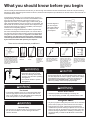
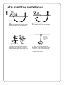
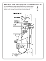
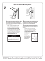
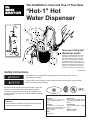
The Installation, Care and Use of Your New
®
“Hot-1” Hot
Water Dispenser
How your hot water
dispenser works
Water is electrically heated to a brewing/cooking hot 190°F (88° C)* by a
compact tank that mounts under the
sink. A thermostat maintains it at this
approximate temperature. When you
push the valve lever, cold water enters
the bottom of the tank and forces hot
water out of the faucet. The system is
vented so the tank is not pressurized.
Valve lever design may vary
*approximate
Safety Instructions
Warnings alert you to hazards or unsafe practices which could result in severe
personal injury or death.
Cautions alert you to hazards or unsafe practices which could result in minor personal
injury or product/property damage.
Please be certain that the person who installs or uses this
appliance carefully reads and understands the Safety
Instructions contained in this manual. This appliance produces extremely hot water. Do not allow children to operate
this appliance.
Important
Do not install this appliance in public areas where there
is unsupervised access to this appliance.
Specifications
Capacity
1/3 gallon (1.3L), up to 40 cups
of 190°F*(88°C) water per
hour.
Thermostat
Snap-action adjustable, factory
preset at approximately 190°F
(88°C).
Electrical
115 volts A.C., 4.3 amps, 500
watts. Energy consumption .95
KWH/day. Three-wire cord &
plug provided.
Construction
Copper tank and valve. Copper
tubing.
Shipping weight
4 lbs. (1.8 kg.)
Valve
Self-closing
P/N42898 04/03
What you should know before you begin
This unit usually mounts behind the sink. Be sure you have enough room between the sink and the wall to mount the unit (see mounting
dimensions). When determining hole location for the unit, ensure that the dispenser spout will drain into the sink and the valve lever will not
hit the back wall or counter.
Connecting the dispenser to your cold water supply requires no
special plumbing. All details are covered in the installation instructions. Be sure that all plumbing connections conform to your
applicable local codes. If your water supply contains sand, grit or
other suspended particles, the use of a filter is recommended. The
filter should not result in the water pressure to the dispenser dropping below 20 pounds per square inch (138kPa). This could prevent the unit from aspirating properly.
A standard 115-volt grounded electrical outlet is required under
the sink for the dispenser’s electrical power. The current drain is
4.3 amps only when the tank is heating. Assure that all electrical
wiring and connections conform to applicable codes. Note: The
wall outlet to your dispenser must have power supplied to it
continuously and must be fused. It should not be controlled
by the same wall switch that operates your disposer.
These are the tools and materials you will need
Cold water line within 16" (40
cm) of the dispenser. A shutoff valve and/or T-fitting(s) to
connect the dispenser to the
cold water line (see step 3 for
examples of connections that
can be used).
Screwdrivers.
Phillips and
flat blade
1/2" - 9/16"
Open end
wrench
115-volt
grounded outlet within 30
inches (76
cm) of the dispenser
Use this diagram if
you are using the
same wall outlet for
the dispenser and
your disposer.
These are the tools you may need
Hand drill. If you have a
galvanized water supply
pipe, you may need a
non-electric drill to make
a small hole.
Basin wrench. If you
intend to use the hand
sprayer hole in your sink
for your dispenser, you
may need a basin
wrench and a 1/8" plug
or a 1/4" cap (not supplied) for the faucet spray
hose line. See step 1 of
installation instructions
for details.
Chassis punch. If you
need to punch a mounting hole in your stainless
steel sink you may need
a 1-3/8" (35 mm) chassis
punch.
Personal Injury
• Dispenses 190°F (88° C) water
which can instantly cause scalds
or burns. Use care when operating
this appliance.
• Do not allow children to operate
this appliance.
Fire Hazard
• To minimize possibility of fire, do not store flammable items
such as rags, paper or aerosol cans near the tank. Do not
store or use gasoline or other flammable vapors and liquids
in the vicinity of this or any other appliance.
A hot water dispenser, like any water heater, has limited life
and will eventually fail. To avoid possible property damage, a
hot water dispenser should be regularly examined for leakage
and replaced when necessary. A drain pan plumbed to an
appropriate drain should be used in those applications
where any leakage could cause property damage.
Electric Shock Hazard
• Disconnect power before installing or servicing unit
• Use only a properly grounded and polarized electric outlet.
Important
• Any time you plan on being away from home for an extended
period of time, unplug the unit’s electrical cord. See step 6.
Personal Injury
• This tank is a non-pressure tank. Do not modify this system.
Do not close vent tube or connect other type faucets or
valves to the tank.
• This unit does not contain a drain plug and should not be
installed where periodic draining is required such as summer
homes. The unit can be drained only by removing it from the
sink and turning it upside down. If draining is necessary, we
recommend that you install an ISE Model H-770 hot water
dispenser.
Let’s start the installation
1
If you have a spray unit like this one
A
on your kitchen sink, the hole is perfect for mounting your Hot-I Dispenser.
PLUG
OR
CAP
FIRST, BE SURE FAUCET IS
B
TURNED OFF. Then unscrew the
spray hose from the bottom of the faucet.
Use a basin
wrench if you
don’t have room
for an ordinary
wrench.
Now pull the spray head and hose
C
entirely out of the hole. Then plug
the faucet tube opening with either a 1/8
Next, remove the nut from the
D
bottom of the washer that is in the
spray hole. If you don’t have enough
inch plug or 1/4 inch cap (not supplied).
room for an ordinary wrench, you may
need the basin wrench.
What if you don’t use a spray hole or don’t want to use it?
You can cut a mounting hole through a stainless steel sink with a 1-3/8" (35mm) chassis
punch such as the one shown at right. Rent or purchase one at your hardware or electrical
supply store. Or, mount the Hot Water Dispenser’s head in a 1-3/8" (35 mm) hole drilled
through your sink countertop with an expandable wood bit. Don’t attempt to drill a hole
through a cast iron or porcelain covered sink unless you have the proper tools.
2 1 2"
4"
(6.4cm)
(10.2cm)
2 9 16"
(6.5cm)
Now we install the dispenser
2
‘B’
‘A’
Spout & spout holder
should not be loose
after mounting.
First tighten
mounting nut
‘B’ and then
tighten wing
nut ‘C’
securely.
‘C’
the unit through the 1-3/8" dia. (35
While holding the dispenser in place with
A Mount
mm) hole in the sink (see note below). Make B spout removed, slip the rubber gasket and
sure the valve lever is in the up position and
feed the spout end of the dispenser through the
sink mounting hole.
Note: To fit the unit through the sink
hole, it will be necessary to remove
the spout. To remove, loosen the set
screw in spout holder approximately
two full turns and pull out spout. After
mounting dispenser in sink, reassemble
the spout making sure the rubber seal
on spout is in place (see sketch below).
Push spout into dispenser as far as it
will go and retighten set screw
approximately two turns.
Personal Injury
Failure to tighten set screw allows easy
removal of spout. Operation of unit with
spout removed could cause injury from
hot water spray.
mounting nut over the valve lever and hand
tighten the nut on the threaded barrel.
the spout so that the water will run
C Align
into the sink and secure the dispenser by
tightening the wing nut from the underside of
the sink.
Important: First ensure mounting
nut B is fully engaged and tightened.
Then tighten wing nut C securely.
The spout and spout holder should
not be loose after tightening
mounting nut B
and wing nut C.
Note: The
dispenser must
be mounted in the
upright (vertical)
position only.
DO NOT plug in the electrical supply cord until the tank is full of water
Next, Let’s make the water connection
3
The recommended
connection can be made
using a shutoff valve.
This is a more complex installation and
should only be
attempted by an
experienced installer with the
proper knowledge and tools.
Electric Shock Hazard
• Never use an electric drill to drill into water
pipes. It can result in an electric shock. Use a
non-electric hand drill.
Attach the valve to a cold water supply
line.
Kitchen
Faucet
Product Damage
• Do not use paste-type pipe sealants on
water line connections.
Doing so may result in clogging of water
passages.
Where plumbing codes
permit, a saddle valve
(not supplied) can be
used to supply water to
the dispenser.
If the saddle valve is to
be used on copper pipe
it is not necessary to predrill any holes. Simply follow the directions
for “self-piercing attachment” included with
the valve.
Note: Saddle valves are susceptible to
dclogging.
Tee fitting
(not supplied)
If the cold water line to
your faucet already has
a shutoff valve, a tee fitting could be added to
supply the hot water
dispenser. Connect the
16" (40.6 cm) long, 1/4"
diameter copper tube
on the dispenser to the
tee fitting as shown.
Add Tee
Fitting
1
/4" Dia.
Tube
Cold water
supply line
DO NOT plug in the electrical supply cord until the tank is full of water
Now let’s connect the water to dispenser
4
Before you start, open
the valve and let a small
amount of water run through it
into a pan. This will flush the
line of sediment.
A
Bend and position the 1/4"
copper line coming from
the dispenser so that it fits into
the shutoff valve. With one
hand, support the copper line
as it comes out of the tank and
bend the tube with the other
hand. Bend the tube carefully.
Do not to kink it.
B
When connecting to a
compression type fitting
tee or valve, remove the nut
and ferrule (a rounded brass
fitting) from the valve. Then,
place the nut followed by the
ferrule over the end of the
tube coming from the dispenser.
C
Push the tube end all the
way into the valve or tee
fitting. Hold the tube end in
position and push the ferrule
down as far as it will go. Now,
tighten the nut over the ferrule
with your fingers. Make sure
the tube end is going straigh
into the hole. Then tighten the
nut firmly with a 1/2" wrench.
D
Flow restriction
• Make sure the bends in tubing are smooth and not kinked.
• Don’t use paste-type sealants on water line connections.
• Tighten compression fittings snug but don’t overtighten.
FILL THE TANK
5
Valve
Lever
First, open the shutoff
valve all the way and
see if your connection is
watertight. If it isn't, redo your
connection.
Important: Never place a
restriction on the delivery
of water from the spout.
Such a restriction prevents
draining the expansion
chamber and could damage the tank.
A
Place the valve lever in
the down position.
Press down on the valve
lever and fill the tank until
water freely runs out of the
spout. Release the valve
lever and the faucet should
turn off. Operate the valve
lever several times letting
the water run to flush out the
lines.
B
DO NOT PLUG IN YET!
6
Fire/Product Damage
• Do not remove or alter the thermal
safety fuse.
• If you suspect the thermal fuse is
open, contact your ISE Authorized
Service Center
Product Damage
• Do not connect electric power until
tank is filled with water.
Failure to do so may damage heating element or thermal safety fuse
and will void your warranty.
Until you have read and
understood the following:
Once the electrical cord is plugged in, it will
take ten to 15 minutes for the water to reach
its 190°F (88°C)* temperature.
(See adjusting temperature procedure).
Your dispenser should now be operating
properly.
When the 190°F (88°C)* temperature is
being reached, you can expect a gurgling or
hissing sound within the tank. This is normal. You might also experience steaming
and/or spitting hot water to come out of the
faucet without turning it on. This also is a
normal function on any initial start up.
Note: The dispenser perks like a coffee
percolator just before the electric thermostat
shuts it off. The rumble is caused by gas
bubbles being driven off by the boiling
water. This is part of the regular operation of
the dispenser.
Now, carefully turn on the faucet for about
20 seconds to draw off that steaming water
and allow the water in the tank to reheat.
Repeat this step one or two more times. This
allows the functional parts of the dispenser
to heat up evenly and work in balance, preventing the steaming and spitting condition.
If steam is still emitted from the faucet, a
thermostat adjustment may be necessary to
slightly decrease the water temperature.
High altitudes: High elevations (Denver,
Colorado, etc.) may require the thermostat
to be lowered to keep the water from boiling
(see adjusting temperature procedure).
*APPROXIMATE
Service/Maintenance Instructions
Adjusting Temperature
What if water is dripping from the spout?
If water drips from the spout, draw 2 or
3 cupfuls while unit is heating. This will
drain any water out of the unit’s expansion chamber. If water still drips prior
to the automatic thermostat shutting
off (you can hear it), turn thermostat
to a slightly lower temperature setting.
If the water pressure occasionally drops below 20
pounds per square inch (138kPa), the expansion
chamber of the tank may not be draining properly.
In such a case, water may drip out of the spout until the incoming water is hot enough to turn off the thermostat. As soon as
adequate water pressure is restored, the next drawing of water
will clear the expansion chamber. Occasional drops in water
pressure will not harm the operation of your unit.
Electric shock hazard
• To prevent electrical shock, disconnect power before removing access cover to service the thermostat.
Scalding hazard
• Do not allow water to boil. May result in severe burns.
Fire/product damage
• Do not remove or alter the thermal safety fuse.
• If you suspect the thermal fuse is open contact your ISE
Authorized Service Center.
Note: Use only mild cleaners to clean the dispenser spout
and plastic components. Use of cleaning agents containing
acids, alkalines and organic solvents will result in deterioration of plastic components.
What to do if something goes wrong
1. If the dispenser’s flow of water slows or stops, make sure
the shutoff valve is not plugged or turned off. To unplug the
valve, turn it all the way off and then open it all the way. This
may dislodge any foreign material. If this does not work, then
unplug the power cord and contact your service center.
2. Be sure dispenser is plugged firmly into a properly grounded
outlet.
Check that fuses and circuit breakers are working. Reread
instruction booklet to assure that you are using correct
operating procedure. Many unnecessary service calls
result in the service agent doing what the owner can do
for himself or herself.
3. Contact your local authorized service center. For the location of your nearest factory authorized service center call
1-800-558-5700 USA (1-800-367-9811 Canada).
4. Write to us if a satisfactory solution is not reached in the
steps above. Our address is shown below.
The thermostat is preset at the factory at approximately 190° F.
If you wish to adjust the water temperature, turn the thermostat
adjustment screw clockwise to increase the temperature and
counterclockwise to decrease it (see illustration above). The
cover must always be in place for the thermostat to respond
properly. Wait for water to heat up or to cool down. Then, draw
some water. If temperature still is not to your liking, repeat the
procedure. Do not allow water to boil.
Full One-Year Warranty
Beginning from the date of installation through one year of use
in your home, we will repair or replace at no charge defects in
material or workmanship which appear in the dispenser. If your
dispenser is replaced rather than repaired, the warranty on the
new unit shall be for the duration of the remaining portion of the
original dispenser’s warranty. Please call the nearest Factory
Authorized Service Center when service is needed.
For the location of your nearest factory authorized service
center, call this toll free number: 1-800-558-5700 USA
(1-800-367-9811 Canada).
Manufactured by IN-SINK-ERATOR
The Emerson logo is a trademark and servicemark of Emerson Electric Co.
In Sink Erator is a division of Emerson Electric Co.
4700 21st STREET, RACINE, WI 53406-5093
ASSEMBLED IN MEXICO
This full one-year warranty applies only if the unit is installed
in accordance with these installation instructions, is used on
circuits and currents specified, and has had normal use and
service.
The foregoing warranty does not apply to damage or inoperation
resulting from accident, alteration, misuse, abuse, improper
installation, installation not in accordance with these instructions
or local electrical and/or plumbing codes or shows evidence
of having been started up “dry”. We do not assume any
responsibility for consequential damage.