1
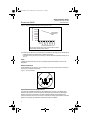
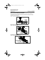
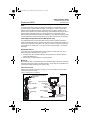
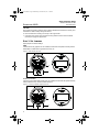
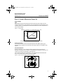
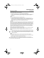
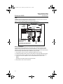
4004_RevDB.fm Page 1 Wednesday, November 23, 2011 3:06 PM Quick Installation Guide 00825-0100-4004, Rev DB December 2011 Rosemount 8800D Rosemount 8800D Series Vortex Flowmeter Start Step 1: Mount the Flowmeter Step 2: Consider Housing Rotation Step 3: Set Jumpers Step 4: Connect Wiring and Power Up Step 5: Verify Configuration Product Certifications End www.rosemount.com English 4004_RevDB.fm Page 2 Wednesday, November 23, 2011 3:06 PM Quick Installation Guide 00825-0100-4004, Rev DB December 2011 Rosemount 8800D © 2011Rosemount Inc. All rights reserved. All marks property of owner. Rosemount and the Rosemount logotype are registered trademarks of Rosemount, Inc. The Emerson logo is a trademark and servicemark of Emerson Electric Co. Rosemount Inc. Emerson Process Management 8200 Market Boulevard Chanhassen, MN USA 55317 T (US) 800-522-6277 T (Intnl) (303) 527-5200 F (952) 906-8889 Neonstraat 1 6718 WX Ede The Netherlands T +31 (0)318 495555 F +31(0) 318 495556 Emerson Process Management Asia Pacific Private Limited 1 Pandan Crescent Singapore 128461 T (65) 6777 8211 F (65) 6777 0947 / (65) 6777 0743 IMPORTANT NOTICE This installation guide provides basic guidelines for the Rosemount® 8800D Vortex Flowmeter. It does not provide instructions for detailed configuration, diagnostics, maintenance, service, troubleshooting, Explosion-proof, Flameproof, or Intrinsically Safe (I.S.) installations. Refer to the Rosemount 8800D reference manual (document number 00809-0100-4004) for more instruction. The manuals and this QIG are also available electronically on www.rosemount.com. WARNING Explosions could result in death or serious injury: Installation of this transmitter in an explosive environment must be in accordance with the appropriate local, national, and international standards, codes, and practices. Please review the approvals section of the Rosemount 8800D reference manual for any restrictions associated with a safe installation. • Before connecting a handheld communicator in an explosive atmosphere, make sure the instruments in the loop are installed in accordance with intrinsically safe or non-incendive field wiring practices. • Verify the operating atmosphere of the flowmeter is consistent with the appropriate product certifications. In an Explosion-proof/Flameproof installation, do not remove the flowmeter covers when power is applied to the unit. Electrical shock can result in death or serious injury • Avoid contact with the leads and terminals. High voltage that may be present on leads can cause electrical shock. 2 4004_RevDB.fm Page 3 Wednesday, November 23, 2011 3:06 PM Quick Installation Guide 00825-0100-4004, Rev DB December 2011 Rosemount 8800D STEP 1: MOUNT THE FLOWMETER Design process piping so the meter body will remain full, with no entrapped air. The vortex flowmeter can be installed in any orientation without affecting accuracy. However, the following are guidelines for certain installations. Vertical Mounting If the vortex flowmeter will be installed in a vertical orientation: • Install upward or downward flow for gas or steam. • Install upward flow for liquids. Figure 1. Vertical Installation Gas Flow Liquid or Gas Flow Horizontal Mounting Figure 2. Horizontal Installation The meter body installed with the electronics to the side of the pipe The meter body installed with the electronics above the pipe Acceptable Preferred For steam and fluids with small solids content, it is recommended to have the flowmeter installed with the electronics to the side of the pipe. This will minimize potential measurement errors by allowing the condensate or solids to flow under the shedder bar without interrupting the vortex shedding. High Temperature Mounting The maximum temperature for integral electronics is dependent on the ambient temperature where the flowmeter is installed. The electronics must not exceed 185 °F (85 °C). Figure 3 shows combinations of ambient and process temperatures needed to maintain a housing temperature of less than 185 °F (85 °C). 3 4004_RevDB.fm Page 4 Wednesday, November 23, 2011 3:06 PM Quick Installation Guide 00825-0100-4004, Rev DB December 2011 Rosemount 8800D 200 (93) 180 (82) 160 (71) 185 °F Housing Temperature Limit 140 (60) 120 (49) 100 (38) 900 (482) 1000 (538) 800 (427) 700 (371) 600 (316) 400 (204) 200 (93) 300 (149) 60 (16) 500 (260) 80 (27) 0 100 (38) Ambient Temperature °F (°C) Figure 3. Rosemount 8800D Ambient/Process Temperature Limits Process Temperature °F (°C) Meter and pipe insulated with 3 inches of ceramic fiber insulation. Horizontal Pipe and Vertical meter position. The following orientations are recommended for applications with high process temperatures. • Install with electronics head beside or below process pipe. • Insulation around pipe may be necessary to maintain ambient temperature below 185 °F (85 °C). NOTE Insulate pipe and meter body only. Do not insulate support tube bracket so heat can be dissipated. Steam Installations Avoid installation shown Figure 4. Such conditions may cause a water-hammer condition at start-up due to trapped condensation. Figure 4. Improper Installation Upstream/Downstream Requirements The Rosemount 8800D Flowmeter may be installed with a minimum of ten straight pipe diameters (D) upstream and five straight pipe diameters (D) downstream by following the K-factor corrections as described in the 8800 Installation Effects Technical Data Sheet (00816-0100-3250). No K-factor correction is required if 35 straight pipe diameters upstream (35D) and 10 straight pipe diameters downstream (10D) are available. 4 4004_RevDB.fm Page 5 Wednesday, November 23, 2011 3:06 PM Quick Installation Guide 00825-0100-4004, Rev DB December 2011 Rosemount 8800D External Pressure/Temperature Transmitters When using pressure and temperature transmitters in conjunction with the 8800D for compensated mass flows, install the transmitters downstream of the Rosemount 8800D flowmeter as shown in Figure 5. Figure 5. Upstream/Downstream Piping P T 4 Downstream 6 Downstream Wafer Style Installation Figure 6. Wafer Style Installation Alignment Ring Alignment Ring Installation Studs and Nuts (Supplied by Customer) Gaskets (Supplied by Customer) Flow Flanged-Style Installation Figure 7. Flanged-Style Flowmeter Installation Installation Bolts and Nuts (Supplied by Customer) Gaskets (Supplied by Customer) Flow 5 4004_RevDB.fm Page 6 Wednesday, November 23, 2011 3:06 PM Quick Installation Guide 00825-0100-4004, Rev DB December 2011 Rosemount 8800D NOTE The required bolt load for sealing the gasket joint is affected by several factors, including operating pressure, gasket material, thickness, and condition. A number of factors also affect the actual bolt load resulting from a measured torque, including condition of bolt threads, friction between the nut head and the flange, and parallelism of the flanges. Due to these application-dependent factors, the required torque for each application may be different. Follow the guidelines outlined in the ASME PCC-1 for proper bolt tightening. Make sure the flowmeter is centered between flanges of the same nominal size as the flowmeter. Insert Integral Temperature Sensor (MTA Option Only) The Temperature Sensor is coiled and attached to the electronics bracket. Remove the plastic band holding the sensor to the electronics bracket and insert temperature sensor into into the hole at the bottom of the meter body. There is no need to remove the opposite end from the electronics. Tighten with 1/2 inch open-end wrench approximately 1 1/4 turns past finger-tight. Remote Electronics If you order one of the remote electronics options (options R10, R20, R30, R33, R50, or RXX), the flowmeter assembly ships in two parts: 1. The meter body with an adapter installed in the support tube and an interconnecting coaxial cable attached to it. 2. The electronics housing installed on a mounting bracket. Mounting Mount the meter body in the process flow line as described earlier in this section. Mount the bracket and electronics housing in the desired location. The housing can be repositioned on the bracket to facilitate field wiring and conduit routing. Cable Connections Refer to Figure 8 and the instructions on page 7 to connect the loose end of the coaxial cable to the electronics housing. Figure 8. Remote Electronics Installation 1/2 NPT Conduit Adapter or Cable Gland (Supplied by Customer) Electronics Housing Coaxial Cable Meter Adapter Union Washer Nut Sensor Cable Nut Support Tube Meter Body Ground Connection Housing Base Screw Housing Adapter Housing Adapter Screws NOTE Consult factory for SST installation 6 Coaxial Cable Nut Conduit Adapter (optional - supplied by customer) 4004_RevDB.fm Page 7 Wednesday, November 23, 2011 3:06 PM Quick Installation Guide 00825-0100-4004, Rev DB December 2011 Rosemount 8800D 1. If you plan to run the coaxial cable in conduit, carefully cut the conduit to the desired length to provide for proper assembly at the housing. A junction box may be placed in the conduit run to provide a space for extra coaxial cable length. CAUTION The coaxial remote cable cannot be field terminated or cut to length. Coil any extra coaxial cable with no less than a 2-in. (51 mm) radius. 2. Slide the conduit adapter or cable gland over the loose end of the coaxial cable and fasten it to the adapter on the meter body support tube. 3. If using conduit, route the coaxial cable through the conduit. 4. Place a conduit adapter or cable gland over the end of the coaxial cable. 5. Remove the housing adapter from the electronics housing. 6. Slide the housing adapter over the coaxial cable. 7. Remove one of the four housing base screws. 8. Attach and securely tighten the coaxial cable nut to the connection on the electronics housing. 9. Attach the coaxial cable ground wire to the housing via the housing base ground screw. 10. Align the housing adapter with the housing and attach with three screws. 11. Tighten the conduit adapter or cable gland to the housing adapter. CAUTION To prevent moisture from entering the coaxial cable connections, install the interconnecting coaxial cable in a single dedicated conduit run or use sealed cable glands at both ends of the cable. NOTE Refer to the User Manual for details for the CPA option. STEP 2: CONSIDER HOUSING ROTATION The entire electronics housing may be rotated in 90° increments for easy viewing. Use the following steps to change the housing orientation: 1. Loosen the three housing rotation set screws at the base of the electronics housing with a 5/32" hex wrench by turning the screws clockwise (inward) until they clear the support tube. 2. Slowly pull the electronics housing out of the support tube. CAUTION Do not pull the housing more than 1.5-in. (40 mm) from the top of the support tube until the sensor cable is disconnected. Damage to the sensor may occur if this sensor cable is stressed. 3. Unscrew the sensor cable from the housing with a 5/16-in. open end wrench. 4. Rotate the housing to the desired orientation. 5. Hold it in this orientation while you screw the sensor cable onto the base of the housing. 7 4004_RevDB.fm Page 8 Wednesday, November 23, 2011 3:06 PM Quick Installation Guide 00825-0100-4004, Rev DB December 2011 Rosemount 8800D CAUTION Do not rotate the housing while the sensor cable is attached to the base of the housing. This will stress the cable and may damage the sensor. 6. Place the electronics housing into the top of the support tube. 7. Use a 5/32” hex wrench to turn the three housing rotation screws counter-clockwise (outward) to engage the support tube. STEP 3: SET JUMPERS Adjust jumpers to desired settings. HART If alarm and security jumpers are not installed, the flowmeter will operate normally with the default alarm condition alarm high and the security off. Figure 9. HART Jumpers and LCD LO HI ALARM SECURITY OFF ON FOUNDATION fieldbus If security and simulate enable jumpers are not installed, the flowmeter will operate normally with the default security off and simulate enable off. Figure 10. FOUNDATION fieldbus Jumpers and LCD ON OFF SIMULATE ENABLE SECURITY ON 8 OFF 4004_RevDB.fm Page 9 Wednesday, November 23, 2011 3:06 PM Quick Installation Guide 00825-0100-4004, Rev DB December 2011 Rosemount 8800D STEP 4: CONNECT WIRING AND POWER UP Power Supply HART The dc power supply should provide power with less than two percent ripple. The total resistance load is the sum of the resistance of the signal leads and the load resistance of the controller, indicator, and related pieces. Note that the resistance of intrinsic safety barriers, if used, must be included. Figure 11. Load Limitation Maximum Loop Resistance = 41.7 (Power Supply Voltage - 10.8) Load (Ohms) 1250 1000 Operating Region 500 0 42 10.8 Power Supply (Volts) The Field Communicator requires a minimum loop resistance of 250 FOUNDATION Fieldbus The flowmeter requires 9-32 Vdc at the power terminals. Each fieldbus power supply requires a power conditioner to decouple the power supply output from the fieldbus wiring segment. Conduit Installation Prevent condensation in any conduit from flowing into the housing by mounting the flowmeter at a high point in the conduit run. If the flowmeter is mounted at a low point in the conduit run, the terminal compartment could fill with fluid. If the conduit originates above the flowmeter, route conduit below the flowmeter before entry. In some cases a drain seal may need to be installed. Figure 12. Proper Conduit Installation with Rosemount 8800D Conduit Line Conduit Line 9 4004_RevDB.fm Page 10 Wednesday, November 23, 2011 3:06 PM Quick Installation Guide Rosemount 8800D 00825-0100-4004, Rev DB December 2011 Use the following steps to wire the flowmeter: 1. Remove the housing cover on the side marked FIELD TERMINALS. 2. Connect the positive lead to the “+” terminal and the negative lead to the “-” terminal as shown in Figure 13 for HART installations and Figure 14 for FOUNDATION fieldbus installations. NOTE FOUNDATION fieldbus terminals are not polarity sensitive. 3. For HART installations utilizing the pulse output, connect the positive lead to the “+” terminal of the pulse output and the negative lead to the “-” terminal of the pulse output as shown in Figure 13. A separate 5 to 30 Vdc power supply is required for the pulse output. Maximum switching current for the pulse output is 120 mA. CAUTION Do not connect the powered signal wiring to the test terminals. Power could damage the test diode in the test connection. Twisted pairs are required to minimize noise pick up in the 4 20 mA signal and digital communication signal. For high EMI/RFI environments, shielded signal wire is required and preferred in all other installations. Use 24 AWG or larger wire and do not exceed 5,000 feet (1,500 meters). For FOUNDATION fieldbus use wire specifically designed for fieldbus installations for maximum performance. For ambient temperatures above 140 °F (60 °C) use wire rated to 176 °F (90 °C). Figure 13 shows wiring connections necessary to power a Rosemount 8800D and enable communications with a hand-held Field Communicator. Figure 14 shows wiring connections necessary to power the 8800D with FOUNDATION fieldbus. 4. Plug and seal unused conduit connections. Use pipe sealing tape or paste on threads to ensure a moisture-tight seal. Housing conduit entries marked with M20 will require M-20 x 1.5 blanking plug thread. Unmarked conduit entries will require a 1/2 -14 NPT blanking plug thread. NOTE Straight threads require a minimum of three (3) wraps of tape to obtain a tight seal. 5. If applicable, install wiring with a drip loop. Arrange the drip loop so the bottom is lower than the conduit connections and the flowmeter housing. Rosemount 8800D Vortex units ordered with painted meter body may be subject to electrostatic discharge. To avoid electrostatic charge build-up, do not rub the meter body with a dry cloth or clean with solvents. 10 4004_RevDB.fm Page 11 Wednesday, November 23, 2011 3:06 PM Quick Installation Guide 00825-0100-4004, Rev DB December 2011 Rosemount 8800D Figure 13. Flowmeter Wiring Diagrams for HART protocol 4-20 mA Wiring RL 250 + Power Supply - 4-20 mA and Pulse Wiring with Electronic Totalizer/Counter RL 250 + Power Supply - Power Supply with Counter + 11 4004_RevDB.fm Page 12 Wednesday, November 23, 2011 3:06 PM Quick Installation Guide 00825-0100-4004, Rev DB December 2011 Rosemount 8800D NOTE Installation of the transient protection terminal block does not provide transient protection unless the Rosemount 8800D case is properly grounded. Figure 14. Flowmeter Wiring Diagram for FOUNDATION fieldbus protocol Field Wiring Diagram Integrated Power Conditioner and Filter 6234 ft (1900 m) max (depending upon cable characteristics) Terminators Fieldbus Segment (The power supply, filter, first terminator, and configuration tool are typically located in the control room.) (Spur) (Spur) (Trunk) Power Supply Devices 1 through 16* * Intrinsically safe installations may allow fewer devices per I.S. barrier. Cover Jam Screw For transmitter housings shipped with a cover jam screw, the screw should be properly installed once the transmitter has been wired and powered up. The cover jam screw is intended to disallow the removal of the transmitter cover in flameproof environments without the use of tooling. Follow these steps to install the cover jam screw: 1. Verify that the cover jam screw is completely threaded into the housing. 2. Install the transmitter housing cover and verify that the cover is tight against the housing. 3. Using an M4 hex wrench, loosen the jam screw until it contacts the transmitter cover. 4. Turn the jam screw an additional 1/2 turn counterclockwise to secure the cover. NOTE: Application of excessive torque may strip the threads. 5. Verify that the cover cannot be removed. 12 4004_RevDB.fm Page 13 Wednesday, November 23, 2011 3:06 PM Quick Installation Guide 00825-0100-4004, Rev DB December 2011 Rosemount 8800D STEP 5: VERIFY CONFIGURATION Before operating the Rosemount 8800D in an installation, you should review the configuration data to ensure that it reflects the current application. In most cases, all of these variables are pre-configured at the factory. Configuration may be required if your 8800D is not configured or if the configuration variables need revision. Rosemount recommends the following variables are reviewed before startup: HART Configuration • • • • • • • • • • • • • • • • • Tag Transmitter Mode Process Fluid Reference K-Factor Flange Type Mating Pipe ID PV Units PV Damping Process Temperature Damping Fixed Process Temperature Auto Adjust Filter LCD Display Configuration (For units with a display only) Density Ratio (For Standard or Normal flow units only) Process Density and Density Units (For mass flow units only) Variable Mapping Range Values Pulse Output Configuration (For units with a pulse output only) FOUNDATION fieldbus Configuration • • • • • • • • • • • • Tag Transmitter Mode Process Fluid Reference K-Factor Flange Type Mating Pipe ID PV Units (Configured in the AI block) Flow Damping Process Temperature Damping Fixed Process Temperature Auto Adjust Filter LCD Display Configuration (For units with a display only) • Density Ratio (For Standard or Normal flow units only) • Process Density and Density Units (For mass flow units only) 13 4004_RevDB.fm Page 14 Wednesday, November 23, 2011 3:06 PM Quick Installation Guide Rosemount 8800D 00825-0100-4004, Rev DB December 2011 Table 1. Fast Keys for Rosemount 8800D Device Revision 1 DD Revision 2 and Device Revision 2 DD Revision 1 Function HART Fast Key Function HART Fast Key Alarm Jumpers 1, 4, 2, 1, 3 Meter Body Number 1, 4, 1, 5 Analog Output 1, 4, 2, 1 Minimum Span 1, 3, 8, 3 Auto Adjust Filter 1, 4, 3, 1, 4 Num Req Preams 1, 4, 2, 3, 2 Base Time Unit 1, 1, 4, 1, 3, 2 Poll Address 1, 4, 2, 3, 1 Base Volume Unit 1, 1, 4, 1, 3, 1 Process Fluid Type 1, 3, 2, 2 Burst Mode 1, 4, 2, 3, 4 Process Variables 1, 1 Burst Option 1, 4, 2, 3, 5 Pulse Output 1, 4, 2, 2, 1 Burst Variable 1 1, 4, 2, 3, 6, 1 Pulse Output Test 1, 4, 2, 2, 2 Burst Variable 2 1, 4, 2, 3, 6, 2 PV Damping 1, 3, 9 Burst Variable 3 1, 4, 2, 3, 6, 3 PV Mapping 1, 3, 6, 1 Burst Variable 4 1, 4, 2, 3, 6, 4 PV Percent Range 1, 1, 2 Burst Xmtr Variables 1, 4, 2, 3, 6 QV Mapping 1, 3, 6, 4 Conversion Number 1, 1, 4, 1, 3, 4 Range Values 1, 3, 8 D/A Trim 1, 2, 5 Review 1, 5 Date 1, 4, 4, 5 Revision Numbers 1, 4, 4, 7 Descriptor 1, 4, 4, 3 Scaled D/A Trim 1, 2, 6 Density Ratio 1, 3, 2, 4, 1, 1 Self Test 1, 2, 1, 5 Device ID 1, 4, 4, 7, 6 Signal to Trigger Ratio 1, 4, 3, 2, 2 Electronics Temp 1, 1, 4, 7, 1 STD/ Nor Flow Units 1, 1, 4, 1, 2 Electronics Temp Units 1, 1, 4, 7, 2 Special Units 1, 1, 4, 1, 3 Filter Restore 1, 4, 3, 3 Status 1, 2, 1, 1 Final Assembly Number 1, 4, 4, 7, 5 SV Mapping 1, 3, 6, 2 Fixed Process Density 1, 3, 2, 4, 2 Tag 1, 3, 1 Fixed Process Temperature 1, 3, 2, 3 Total 1, 1, 4, 4, 1 Flange Type 1, 3, 4 Totalizer Control 1, 1, 4, 4 Flow Simulation 1, 2, 4 Transmitter Mode 1, 3, 2, 1 Installation Effects 1, 4, 1, 6 TV Mapping 1, 3, 6, 3 K-factor (Reference) 1, 3, 3 Trigger Level 1, 4, 3, 2, 5 Local Display 1, 4, 2, 4 URV 1, 3, 8, 1 Loop Test 1, 2, 2 User Defined Units 1, 1, 4, 1, 3, 3 Low Flow Cutoff 1, 4, 3, 2, 3 USL 1, 3, 8, 4 Low Pass Filter 1, 4, 3, 2, 4 Shedding Frequency 1, 1, 4, 6 LRV 1, 3, 8, 2 Variable Mapping 1, 3, 6 LSL 1, 3, 8, 5 Velocity Flow 1, 1, 4, 3 Manufacturer 1, 4, 4, 1 Velocity Flow Base 1, 1, 4, 3, 3 Mass Flow 1, 1, 4, 2, 1 Volumetric Flow 1, 1, 4, 1 Mass Flow Units 1, 1, 4, 2, 2 Wetted Material 1, 4, 1, 4 Mating Pipe ID (Inside Diameter) 1, 3, 5 Write Protect 1, 4, 4, 6 Message 1, 4, 4, 4 NOTE For detailed configuration information see the Rosemount 8800D Vortex Flowmeter manual (00809-0100-4004). 14 4004_RevDB.fm Page 15 Wednesday, November 23, 2011 3:06 PM Quick Installation Guide 00825-0100-4004, Rev DB December 2011 Rosemount 8800D Table 2. Fast Keys for Rosemount 8800D Device Revision 2 DD Revision 3 Function HART Fast Key Function Alarm Direction 1, 3, 1, 3, 2 Percent of Range Analog Output 3, 4, 3, 1 Polling Address Analog Trim 3, 4, 3, 6 Primary Variable Damping Base Time Unit 2, 2, 2, 3, 2 Primary Variable Base Volume Unit 2, 2, 2, 3, 1 Process Density Units Burst Mode 2, 2, 7, 2 Process Fluid Type Burst Option 2, 2, 7, 3 Process Temp Units Burst Slot 0 2, 2, 7, 4, 1 Process Variables Burst Slot 1 2, 2, 7, 4, 2 Pulse Output Burst Slot 2 2, 2, 7, 4, 3 Pulse Output Test Burst Slot 3 2, 2, 7, 4, 4 Recall Factory Calibration Burst Variable Mapping 2, 2, 7, 4, 5 Reference K-Factor Compensated K-Factor 2, 2, 1, 2, 2 Reset Transmitter Conversion Number 2, 2, 2, 3, 4 Restore Default Filters Date 2, 2, 8, 2, 1 Revision Numbers Descriptor 2, 2, 8, 2, 2 Scaled Analog Trim Density Ratio 2, 2, 3, 3, 2 2nd Variable Device ID 2, 2, 8, 1, 5 Self Test Display 2, 1, 1, 2 Set Variable Mapping Electronics Temp 3, 2, 5, 4 Shedding Frequency Electronics Temp Units 2, 2, 2, 2, 5 Signal Strength Final Assembly Number 2, 2, 8, 1, 4 Special Flow Unit Fixed Process Density 2, 2, 1, 1, 5 Special Volume Unit Fixed Process Temperature 2, 2, 1, 1, 4 Status Flange Type 2, 2, 1, 4, 2 Tag Flow Simulation 3, 5, 1 3rd Variable 4th Variable 2, 2, 2, 1, 4 Total Installation Effects 2, 2, 1, 1, 7 Totalizer Configuration Lower Range Value 2, 2, 4, 1, 4 Totalizer Control Lower Sensor Limit 2, 2, 4, 1, 5, 2 Transmitter Mode Loop Test 3, 5, 2, 6 Trigger Level Low Flow Cutoff 2, 1, 4, 3 Upper Range Value Low-pass Corner Frequency 2, 1, 4, 4 Upper Sensor Limit Manufacturer 2, 2, 8, 1, 2 Velocity Flow Mass Flow 3, 2, 3, 6 Velocity Flow Units Mass Flow Units 2, 2, 2, 2, 4 Velocity Measurement Base Mating Pipe ID (Inside Diameter) 2, 2, 1, 1, 6 Volume Flow Message 2, 2, 8, 2, 3 Volume Flow Units Meter Body Number 2, 2, 1, 4, 5 Wetted Material Minimum Span 2, 2, 4, 1, 6 Write Protect Optimize DSP 2, 1, 1, 3 HART Fast Key 3, 4, 3, 2 2, 2, 7, 1 2, 1, 4, 1 2, 2, 2, 1, 1 2, 2, 2, 2, 6 2, 2, 1, 1, 2 2, 2, 3, 1, 2 3, 2, 1 3, 2, 4, 4 3, 5, 3, 4 3, 4, 3, 8 2, 2, 1, 2, 1 3, 4, 1, 2 2, 1, 4, 6 2, 2, 8, 3 3, 4, 3, 7 2, 2, 2, 1, 2 3, 4, 1, 1 2, 2, 2, 1, 5 3, 2, 4, 2 3, 2, 5, 2 2, 2, 2, 3, 5 2, 2, 2, 3, 3 1, 1, 1 2, 2, 8, 1, 1 2, 2, 2, 1, 3 1, 3, 6, 1 1, 3, 6, 3 1, 3, 6, 2 2, 2, 1, 1, 1 2, 1, 4, 5 2, 2, 4, 1, 3 2, 2, 4, 1, 5, 1 3, 2, 3, 4 2, 2, 2, 2, 2 2, 2, 2, 2, 3 3, 2, 3, 2 2, 2, 2, 2, 1 2, 2, 1, 4, 1 2, 2, 8, 1, 6 15 4004_RevDB.fm Page 16 Wednesday, November 23, 2011 3:06 PM Quick Installation Guide Rosemount 8800D 00825-0100-4004, Rev DB December 2011 PRODUCT CERTIFICATIONS Approved Manufacturing Locations Rosemount Inc. — Eden Prairie, Minnesota, USA Emerson Process Management BV - Ede, The Netherlands Emerson Process Management Flow Technologies Company, Ltd - Nanjing, Jiangsu Province, P.R. China Flameproof enclosure Ex d protection type in accordance with IEC 60079-1, EN 60079-1 • Transmitters with Flameproof enclosure type protection shall only be opened when power is removed. • Closing of entries in the device must be carried out using the appropriate Ex d cable gland or blanking plug. Unless otherwise marked on housing, the standard conduit entry thread forms are 1/2-14 NPT. Type n protection type in accordance with IEC 60079-15, EN 60079-15 Closing of entries in the device must be carried out using the appropriate Ex e or Ex n cable gland and metal blanking plug or any appropriate ATEX or IECEx approved cable gland and blanking plug with IP66 rating certified by an EU approved certification body. European Directive Information The CE Declaration of Conformity for all applicable European directives for this product can be found on our website at www.rosemount.com. A hard copy may be obtained by contacting our local sales office. ATEX Directive Rosemount Inc. complies with the ATEX Directive. European Pressure Equipment Directive (PED) Rosemount 8800D Vortex Flowmeter Line Size 40 mm to 300 mm Certificate Number 59552-2009-CE-HOU-DNV 0575 Module H Conformity Assessment Mandatory CE-marking for flowmeters in accordance with Article 15 of the PED can be found on the flowtube body. Flowmeter categories I – III use module H for conformity assessment procedures. Rosemount 8800 Vortex Flowmeter Line Size 15 mm and 25 mm Sound Engineering Practice Flowmeters that are SEP are outside the scope of PED and cannot be marked for compliance with PED. 16 4004_RevDB.fm Page 17 Wednesday, November 23, 2011 3:06 PM Quick Installation Guide 00825-0100-4004, Rev DB December 2011 Rosemount 8800D Hazardous Location Certifications Rosemount 8800D North American Certifications Factory Mutual (FM) E5 Explosion-Proof for Class I, Division 1, Groups B, C, and D; Dust-ignition proof for Class II/III, Division 1, Groups E, F, and G; Temperature Code T6 (-50 °C Ta 70 °C) Factory Sealed Enclosure Type 4X I5 Intrinsically safe for use in Class I, II, III Division 1, Groups A, B, C, D, E, F, G; Non-incendive for Class I, Division 2, Groups A, B, C, and D. NIFW (Non-incendive Field Wiring) when installed per Rosemount Drawing 08800-0116 Temperature Code T4 (-50 °C Ta 70 °C) 4-20 mA HART Temperature Code T4 (-50 °C Ta 60 °C) Fieldbus IE FISCO for Class I, Division 1, Groups A, B, C, and D. FNICO for Class 1 Division 2, Groups A, B, C, and D. Temperature Code T4 (-50 °C Ta 60 °C) when installed per Rosemount control drawing 08800-0116. Enclosure Type 4X K5 E5 and I5 Combination Special conditions for safe use (x) When fitted with 90V transient suppresors (T1 Option), the equipment is not capable of passing the 500V insulation test. This must be taken into account upon installation. The enclosure may be made of an aluminum alloy, and given a protective polyurethane paint finish: care should be taken to protect the housing from impact or abrasion. Canadian Standards Association (CSA) E6 Explosion-Proof for Class I, Division 1, Groups B, C, and D; Dust-ignition proof for Class II and Class III, Division 1, Groups E, F, and G; Class I, Zone 1, Ex d[ia] IIC CSA 06.1674267 Temperature Code T6 (-50 °C Ta 70 °C) Factory Sealed Single Seal. Enclosure Type 4X I6 Intrinsically safe for use in Class I, II, III Division 1, Groups A, B, C, D, E, F, G; Non-incendive for Class I, Division 2, Groups A, B, C and D Temperature Code T4 (-50 °C Ta 70 °C) 4-20 mA HART Temperature Code T4 (-50 °C Ta 60 °C) Fieldbus Single Seal. Enclosure Type 4X 17 4004_RevDB.fm Page 18 Wednesday, November 23, 2011 3:06 PM Quick Installation Guide Rosemount 8800D IF 00825-0100-4004, Rev DB December 2011 FISCO for Class I, Division 1, Groups A, B, C, and D; FNICO for Class 1 Division 2, Groups A, B, C, and D. Temperature Code T4 (-50 °C Ta 60 °C). When installed per Rosemount drawing 08800-0112 Enclosure Type 4X K6 E6 and I6 Combination Combination Certifications KB E5, I5, E6, and I6 Combination European Certifications ATEX Intrinsic Safety EN 60079-0 : 2009 EN 60079-11 : 2007 I1 Certification No. Baseefa05ATEX0084X ATEX Marking II 1 G Ex ia IIC T4 Ga (-60 °C Ta 70 °C) 4-20 HART (-60 °C Ta 60 °C) Fieldbus 4-20 mA HART Entity Parameters Ui = 30 VDC Ii(1) = 185 mA Pi(1) = 1.0 W Ci = 0 F Li < 0.97 mH (1) Fieldbus Entity Parameters Ui = 30 VDC Ii = 300 mA Pi = 1.3 W Ci = 0 F Li < 10 Total for transmitter 0575 ATEX FISCO/FNICO IA Certification No. Baseefa05ATEX0084X ATEX Marking II 1 G Ex ia IIC T4 Ga (-60 °C Ta 60 °C) 0575 Input Parameters: Ui = 17.5 Vdc Ii = 380 mA Pi = 5.32 W Ci = 0 F Li < 10 H Special conditions for safe use (x) When fitted with 90V transient suppressors (T1 Option), the equipment is not capable of passing the 500V isolation test. This must be taken into account upon installation. 18 4004_RevDB.fm Page 19 Wednesday, November 23, 2011 3:06 PM Quick Installation Guide 00825-0100-4004, Rev DB December 2011 Rosemount 8800D The enclosure may be made from aluminium alloy and given a protective polyurethane paint finish; however, care should be taken to protect it from impact or abrasion when located in Zone 0 environment. The polyurethane paint finish may constitute an electrostatic hazard and must only be cleaned with a damp cloth. When the equipment is installed, particular precautions must be taken to ensure taking into account the effect of process fluid temperature, that the ambient temperature of the electrical housing of the equipment meets the marked protection type temperature range. ATEX Type N Certification EN 60079-0 : 2009 EN 60079-11 : 2007 EN 60079-15 : 2010 N1 Certification No. Baseefa05ATEX0085X ATEX Marking II 3 G Ex nA ic IIC T5 Gc (-50 °C Ta 70 °C) 4 -20 mA HART (-50 °C Ta 60 °C) Fieldbus Input Parameters: Maximum Working Voltage = 42 VDC Max 4-20 mA HART Maximum Working Voltage = 32 VDC Max Fieldbus Special conditions for safe use (x) When fitted with 90V transient suppressors (T1 Option), the equipment is not capable of passing the 500V isolation test. This must be taken into account upon installation. The enclosure may be made from aluminium alloy with a protective polyurethane paint finish. The polyurethane paint finish may constitute and electrostatic hazard and must only be cleaned with a damp cloth. When the equipment is installed, particular precautions must be taken to ensure, taking into account the effect of process fluid temperature, that the ambient temperature of the electrical housing of the equipment meets the marked protection type temperature range. ATEX Flameproof Certification EN 60079-0 : 2009 EN 60079-1 : 2007 EN 60079-11 : 2007 19 4004_RevDB.fm Page 20 Wednesday, November 23, 2011 3:06 PM Quick Installation Guide Rosemount 8800D E1 00825-0100-4004, Rev DB December 2011 Certification No. KEMA99ATEX3852X Integral Flowmeter marked: II 1/2 G Ex d [ia] IIC T6 Ga/Gb (-50 °C Ta 70 °C) Remote Transmitter marked: II 2(1) G Ex d [ia] IIC T6 Ga/Gb (-50 °C Ta 70 °C) with meter body marked: II 1 G Ex ia IIC T6 Ga 42 VDC Max 4-20 mA HART 32 VDC Max Fieldbus Um = 250V Installation instructions The cable and conduit entry devices shall be of a certified flameproof type Ex d, suitable for the conditions of use and correctly installed. Unused apertures shall be closed with suitable blanking elements. When the ambient temperature at the cable or conduit entries exceed 60 °C, cables suitable for at least 90 °C shall be used. Care must be taken when installing the equipment with process fluid in the range of -202 °C to +427 °C, as the ambient temperature for the electronics and electronics housing must stay in the temperature range of -50 °C to +70 °C. The remote mounted sensor may only be connected to the transmitter with the associated cable, supplied by the manufacturer. Special conditions for safe use (x) For information regarding the dimensions of the flameproof joints the manufacturer shall be contacted. The Flowmeter shall be provided with special fasteners of property class A2-70 or A4-70. ATEX Dust Certification EN 60241-0 : 2006 EN 60241-1 : 2004 ND Certification No. Baseefa05ATEX0086/3 II 1D Ex tD A20 IP66 T90 °C (-20 °C Ta 70 °C) 42 VDC Max 4-20 mA HART 32 VDC Max Fieldbus K1 20 E1, I1, N1, and ND Combination 4004_RevDB.fm Page 21 Wednesday, November 23, 2011 3:06 PM Quick Installation Guide 00825-0100-4004, Rev DB December 2011 Rosemount 8800D International IECEx Certifications Intrinsic Safety IEC 60079-0 : 2007 IEC 60079-11 : 2006 I7 Certification No. IECEx BAS05.0028X Ex ia IIC T4 Ga (-60 °C Ta 70 °C) 4-20 mA HART (-60 °C Ta 60 °C) Fieldbus 4-20 mA HART Entity Parameters Ui = 30 VDC Ii(1) = 185 mA Pi(1) = 1.0 W Ci = 0 F Li < 0.97 mH (1) Fieldbus Entity Parameters Ui = 30 VDC Ii = 300 mA Pi = 1.3 W Ci = 0 F Li < 10 H Total for transmitter FISCO/FNICO IG Certification No. IECEx BAS 05.0028X Ex ia IIC T4 Ga (-60 °C Ta 60 °C) Input Parameters: Ui = 17.5 Vdc Ii = 380 mA Pi = 5.32 W Ci = 0 F Li 10H Special conditions for safe use (x) When fitted with 90V transient suppressors (T1 Option), the equipment is not capable of passing the 500V isolation test. This must be taken into account upon installation. The enclosure may be made from aluminium alloy and given a protective polyurethane paint finish; however, care should be taken to protect it from impact or abrasion when located in Zone 0 environment. The polyurethane paint finish may constitute an electrostatic hazard and must only be cleaned with a damp cloth. When the equipment is installed, particular precautions must be taken to ensure, taking into account the effect of process fluid temperature, that the ambient temperature of the electrical housing of the equipment meets the marked protection type temperature range. 21 4004_RevDB.fm Page 22 Wednesday, November 23, 2011 3:06 PM Quick Installation Guide Rosemount 8800D 00825-0100-4004, Rev DB December 2011 Type N Certification IEC 60079-0 : 2007 IEC 60079-11 : 2006 IEC 60079-15 : 2010 N7 Certification No. IECEx BAS05.0029X Ex nA ic IIC T5 Gc (-40 °C Ta 70 °C) 4-20 mA HART (-40 °C Ta 60 °C) Fieldbus Maximum Working Voltage = 42 VDC 4-20 mA HART Maximum Working Voltage = 32 VDC Fieldbus Special conditions for safe use (x) When fitted with 90V transient suppressors (T1 Option), the equipment is not capable of passing the 500V isolation test. This must be taken into account upon installation. The enclosure may be made from aluminium alloy with a protective polyurethane paint finish. The polyurethane paint finish may constitute an electrostatic hazard and must only be cleaned with a damp cloth. When the equipment is installed, particular precautions must be taken to ensure, taking into account the effect of process fluid temperature, that the ambient temperature of the electrical housing of the equipment meets the marked protection type temperature range. Flameproof Certification IEC 60079-0 : 2007-10 IEC 60079-1 : 2007-04 IEC 60079-11 : 2006 IEC 60079-26 : 2006 E7 Certification No. IECEx KEM05.0017X Integral Flowmeter marked: Ex d [ia] IIC T6 Ga/Gb (-50 °C Ta 70 °C) Remote Transmitter marked: Ex d [ia] IIC T6 Ga/Gb (-50 °C Ta 70 °C) with meter body marked: Ex ia IIC T6 Ga 42 VDC Max 4-20 mA HART 32 VDC Max Fieldbus Um = 250V Installation instructions The cable and conduit entry devices shall be of a certified flameproof type Ex d, suitable for the conditions of use and correctly installed. Unused apertures shall be closed with suitable blanking elements. When the ambient temperature at the cable or conduit entries exceed 60 °C, cables suitable for at least 90 °C shall be used. 22 4004_RevDB.fm Page 23 Wednesday, November 23, 2011 3:06 PM Quick Installation Guide 00825-0100-4004, Rev DB December 2011 Rosemount 8800D Care must be taken when installing the equipment with process fluid in the range of -202 °C to +427 °C, as the ambient temperature for the electronics and electronics housing must stay in the temperature range of -50 °C to +70 °C. The remote mounted sensor may only be connected to the transmitter with the associated cable, supplied by the manufacturer. Special conditions for safe use (x) For information regarding the dimensions of the flameproof joints, the manufacturer shall be contacted. The Flowmeter shall be provided with special fasteners of property class A2-70 or A4-70. Care must be taken when installing the equipment with process fluid in the range of -202 °C to +427 °C, as the ambient temperature for the electronics and electronics housing must stay in the temperature range of -50 °C to +70 °C. The remote mounted sensor shall only be connected to the transmitter with the associated cable, supplied by the manufacturer. Chinese Certifications (NEPSI) Flameproof Certification E3 Certification No. GYJ071327X Ex d [ia] IIC T6 (-50 °C to 70 °C) Intrinsic Safety I3 Certification No. GYJ071171X Ex ia IIC T4/T5 T4: (-60 °C to 70 °C) T5: (-60 °C to 40 °C) Input Parameters: Ui = 30 Vdc Ii = 185 mA Pi = 1.0 W Ci = 0 F Li = 0.97 mH Type N Certification N3 Certification No. GYJ071193X Ex nAnL IIC T5 (-40 °C to70 °C) 42 Vdc Max K3 E3, I3, and N3 Combination 23 4004_RevDB.fm Page 24 Wednesday, November 23, 2011 3:06 PM Quick Installation Guide Rosemount 8800D Japanese Certifications (TIIS) Flameproof Certification E4 Transmitter - Ex d [ia] T6 Remote Sensor - Ex ia IIC T6 Certificate Description 24 TC17816 8800D with display, without MTA option TC17817 8800D without display, without MTA option TC17905 8800D with display, with MTA option TC17906 8800D without display, with MTA option 00825-0100-4004, Rev DB December 2011 4004_RevDB.fm Page 25 Wednesday, November 23, 2011 3:06 PM Quick Installation Guide 00825-0100-4004, Rev DB December 2011 Rosemount 8800D Figure 15. European Declaration of Conformity 25 4004_RevDB.fm Page 26 Wednesday, November 23, 2011 3:06 PM Quick Installation Guide Rosemount 8800D 26 00825-0100-4004, Rev DB December 2011 4004_RevDB.fm Page 27 Wednesday, November 23, 2011 3:06 PM Quick Installation Guide 00825-0100-4004, Rev DB December 2011 Rosemount 8800D 27 4004_RevDB.fm Page 28 Wednesday, November 23, 2011 3:06 PM Quick Installation Guide Rosemount 8800D 28 00825-0100-4004, Rev DB December 2011