1
cover_6504:cover_6504 2009-02-12 오
9:06 페이지 2
OPERATING INSTRUCTIONS
INSTRUCCIONES DE FUNCIONAMIENTO
MODE D'EMPLOI
RD-6504
AUDIO/VIDEO RECEIVER
RECEPTOR DE AUDIO/VIDEO
RECEPTEUR AUDIO/VIDEO
RD-6504(A)_ENG:RD-6504(A)2009-02-12오 9:03페이지2
ENGLISH
IMPORTANT SAFETY INSTRUCTIONS
1. Read these instructions.
2. Keep these instructions.
3. Heed all warnings.
4. Follow all instructions.
5. Do not use this apparatus near water.
6. Clean only with dry cloth.
7. Do not block any ventilation openings.
Install in accordance with the manufacturer’s instructions.
8. Do not install near any heat sources such as radiators,
heat registers, stoves, or other apparatus (including
amplifiers) that produce heat.
9. Do not defeat the safety purpose of the polarized or
grounding-type plug. A polarized plug has two blades
with one wider than the other.
A grounding type plug has two blades and a third
grounding prong. The wide blade or the third prong are
provided for your safety. If the provided plug does not fit
into your outlet, consult an electrician for replacement of
the obsolete outlet.
10. Protect the power cord from being walked on or pinched
particularly at plugs, convenience receptacles, and the
point where they exit from the apparatus.
11. Only use attachments accessories specified by the
manufacturer.
12. Use only with the cart, stand, tripod, bracket, or table
specified by the manufacturer, or sold with the
apparatus.
When a cart is used, use caution when moving the
cart/apparatus combination to avoid injury from tip-over.
PORTABLE CART WARNING
13. Unplug this apparatus during lightning storms or when
unused for long periods of time.
14. Refer all servicing to qualified service personnel.
Servicing is required when the apparatus has been
damaged in any way, such as power-supply cord or
plug is damaged, liquid has been spilled or objects have
fallen into the apparatus, the apparatus have been
exposed to rain or moisture, does not operate normally,
or has been dropped.
2
RD-6504(A)_ENG:RD-6504(A)2009-02-12오 9:03페이지3
Introduction
This symbol is intended to alert the user to the presence of
uninsulated "dangerous voltage" within the product's
enclosure that may be of sufficient magnitude to constitute
a risk of electric shock to persons.
: TO REDUCE THE RISK OF ELECTRIC
SHOCK, DO NOT REMOVE COVER (OR
BACK). NO USER-SERVICEABLE PARTS
INSIDE. REFER SERVICING TO
QUALIFIED SERVICE PERSONNEL.
CAUTION
This symbol is intended to alert the user to the presence of
important operating and maintenance (servicing)
instructions in the literature accompanying the appliance.
WARNING : TO REDUCE THE RISK OF FIRE OR ELECTRIC SHOCK,
DO NOT EXPOSE THIS APPLIANCE TO RAIN OR MOISTURE.
Caution regarding installation
Note : For heat dispersal, do not install this unit in a confined space such as a bookcase or similar enclosure.
Do not block ventilation openings or stack other equipment on the top.
Note to CATV System Installer :
This reminder is provided to call the CATV system installer’s attention to Article 820-40 of the NEC that provides guidelines for proper
grounding and, in particular, specifies that the cable ground shall be connected to the grounding system of the building, as close to the point
of cable entry as practical.
FCC INFORMATION
This equipment has been tested and found to comply with the limits for a Class B digital device, pursuant to Part 15 of the FCC Rules. These
limits are designed to provide reasonable protection against harmful interference in a residential installation. This equipment generates, uses and
can radiate radio frequency energy and, if not installed and used in accordance with the instructions, may cause harmful interference to radio
communications. However, there is no guarantee that interference will not occur in a particular installation. If this equipment does cause harmful
interference to radio or television reception, which can be determined by turning the equipment off and on, the user is encouraged to try to correct
the interference by one or more of the following measures:
• Reorient or relocate the receiving antenna.
• Increase the separation between the equipment and receiver.
• Connect the equipment into an outlet on a circuit different from that to which the receiver is connected.
• Consult the dealer or an experienced radio/TV technician for help.
Caution : Any changes or modifications in construction of this device which are not expressly approved by the party responsible for compliance
could void the user’s authority to operate the equipment.
This Class B digital apparatus complies with Canadian ICES-003.
Cet appareil numérique de la Classe B est conforme à la norme NMB-003 du Canada.
FOR YOUR SAFETY
U.S.A
CANADA
CAUTION
• Leave a space around the unit for sufficient ventilation.
• Avoid installation in extremely hot or cold locations, or in an area that is
exposed to direct sunlight or heating equipment.
• Keep the unit free from moisture, water, and dust.
• Do not let foreign objects in the unit.
• The ventilation should not be impeded by covering the ventilation
openings with items, such as newspapers, table-cloths, curtains, etc.
• No naked flame sources, such as lighted candles, should be placed on
the unit.
• Please be care the environmental aspects of battery disposal.
• The unit shall not be exposed to dripping or splashing for use.
• No objects filled with liquids, such as vases, shall be placed on the unit.
• Do not let insecticides, benzene, and thinner come in contact with
the set.
• Never disassemble or modify the unit in any way.
■Notes on the AC power cord and the wall outlet.
• The unit is not disconnected from the AC power source(mains) as long
as it is connected to the wall outlet, even if the unit has been turned off.
• To completely disconnect this product from the mains, disconnect the
plug from the wall socket outlet.
• When setting up this product, make sure that the AC outlet you are
using is easily acceptable.
• Disconnect the plug from the wall outlet when not using the unit for long
periods of time.
120 V
Units shipped to the U.S.A and CANADA are designed for operation
on 120 V AC only.
Safety precaution with use of a polarized AC plug.
However, some products may be supplied with a nonpolarized plug.
CAUTION
: To prevent electric shock, match wide blade of
plug to wide slot, fully insert.
ATTENTION
: Pour éviter chocs électriques, introduire la lame
la plus large de la fiche dans la borne
correspondante de la prise et pousser jusqu’ au
fond.
ENERGY STAR® is a U.S. registered mark. As an
ENERGY STAR® Partner, Sherwood has
determined that this product meets the ENERGY
STAR® guidelines for energy efficiency.
3
ENGLISH
READ THIS BEFORE OPERATING YOUR UNIT
RD-6504(A)_ENG:RD-6504(A)2009-02-12오 9:03페이지4
CONTENTS
ENGLISH
•IMPORTANT SAFETY INSTRUCTIONS ............................................................................................................................... 2
Introduction
• READ THIS BEFORE OPERATING YOUR UNIT ................................................................................................................. 3
System Connections ......................................................................................................................................................... 5
Front Panel Controls ....................................................................................................................................................... 11
Remote Controls ............................................................................................................................................................... 13
• REMOTE CONTROL OPERATION RANGE ....................................................................................................................... 14
• LOADING BATTERIES ....................................................................................................................................................... 14
Operations
• LISTENING TO A PROGRAM SOURCE ............................................................................................................................ 15
• SURROUND SOUND .......................................................................................................................................................... 18
• ENJOYING SURROUND SOUND ...................................................................................................................................... 19
• LISTENING TO RADIO BROADCASTS ............................................................................................................................. 24
• RECORDING ....................................................................................................................................................................... 26
• OTHER FUNCTIONS .......................................................................................................................................................... 28
System Setup .................................................................................................................................................................... 29
• SETTING THE SYSTEM .................................................................................................................................................... 31
• SETTING THE INPUT ......................................................................................................................................................... 33
• SETTING THE SPEAKER SETUP ...................................................................................................................................... 34
• SETTING THE CH LEVEL .................................................................................................................................................. 38
• SETTING THE PARAMETER ............................................................................................................................................. 40
Troubleshooting Guide ................................................................................................................................................... 42
Specifications .................................................................................................................................................................... 43
4
RD-6504(A)_ENG:RD-6504(A)2009-02-12오 9:03페이지5
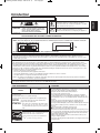
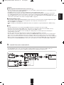
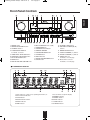
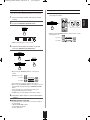
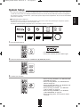
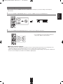
• Please be certain that this unit is unplugged from the AC outlet before making any connections.
• Since different components often have different terminal names, carefully read the operating instructions of the component
connected.
• Be sure to observe the color coding when connecting audio, video and speaker cords.
• Make connections firmly and correctly. If not, it can cause loss of sound, noise or damage to the receiver.
2
3
4
2
8
RD-6504
AUDIO/VIDEO RECEIVER
2
1
POWER SOURCE
120V
POWER CONSUMPTION
60Hz
3.8A
DESIGNED IN USA
MADE IN CHINA
5
2
6
1
7
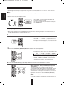
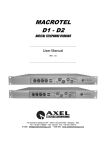
1. CONNECTING ANTENNAS
• Change the position of the FM indoor antenna until you
get the best reception of your favorite FM stations.
• A 75Ω outdoor FM antenna may be used to further
improve the reception. Disconnect the indoor
antenna before replacing it with the outdoor one.
• Place the AM loop antenna as far as possible from the receiver, TV set, speaker cords and the AC
input cord and set it to a direction for the best reception.
• If the reception is poor with the AM loop antenna, an AM outdoor antenna can be used in place of
the AM loop antenna.
5
ENGLISH
System Connections
RD-6504(A)_ENG:RD-6504(A)2009-02-12오 9:03페이지6
ENGLISH
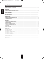
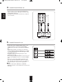
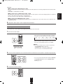
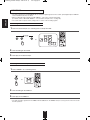
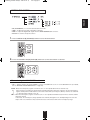
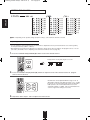
2. CONNECTING VIDEO COMPONENTS
• The jacks of VIDEO 1 may also be connected to a DVD recorder or other digital video recording component. For details, refer
to the operating instructions of the component to be connected.
• The jacks of VIDEO 2 can also be connected to an additional video component such as a cable TV tuner or satellite system.
• There are two types of video jacks (COMPONENT, (composite) VIDEO) for analog video connections and the HDMI
connectors for digital video and audio connections.
Connect them to the corresponding video jacks according to their capability.
• For your reference, the excellence in picture quality is as follows : "HDMI” > "COMPONENT" > "(composite) VIDEO" .
• When making COMPONENT VIDEO connections, connect "Y" to "Y", "PB/CB" to "CB"(or "B-Y", "PB") and "PR/CR" to "CR"(or
"R-Y", "PR").
• When recording video program sources through VIDEO 1 OUT jack or viewing video program sources through MONITOR
OUT jack, you must use the same type of video jacks that you did connect to video playback components such as DVD
player, cable TV tuner, etc.
6
RD-6504(A)_ENG:RD-6504(A)2009-02-12오 9:03페이지7
Continued
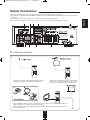
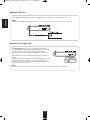
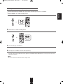
• You can connect the source component (DVD player, etc.) to the display component (TV, projector, etc.) through this receiver
with using a commercially available HDMI cord.
• The HDMI connection can carry uncompressed digital video signals and digital audio signals.
• The HDMI video stream signals (video signals) are theoretically compatible with DVI-D. When connecting to a TV monitor,
etc., equipped with DVI-D connector, it is possible to connect using a commercially available HDMI-DVI converter cord.
Since the HDMI-to-DVI connection cannot carry any audio signals, set the HDMI to OFF to hear the HDMI digital audio signals
on this receiver. (For details, refer to "When selecting the HDMI" on page 32.)
■Copyright protection system
• This unit supports HDCP (High-bandwidth Digital Contents Protection), technology to protect copyright of digital video signals
against illegal duplication. HDCP must also be supported on the components connected to this unit.
• This unit is HDMI Ver. 1.3 compatible.
• HDMI, the HDMI logo and High-Definition Multimedia Interface are trademarks or registered trademarks of HDMI licensing
LLC.
■Notes :
• For stable signal transfer, we recommend using HDMI cords that are a maximum of 5 meters in length.
• Among the components that support HDMI, some components can control other components via the HDMI connector.
However, this unit cannot be controlled by another component via the HDMI connector.
• The audio signals from the HDMI connector (including the sampling frequency and bit length) may be limited by the
component that is connected.
• The video signals will not be output properly if a component incompatible with HDCP is connected.
• If the resolutions of the video signals which are output from the MONITOR OUTs and your monitor TV are not matched, the
picture is not clear, natural or displayed. In this case, change the setting of the resolution on the source component (DVD
player, etc.) to one which the monitor TV can handle. (For details, refer to the operating instructions of the source component.)
• When you want to enjoy only the picture on your TV, not the sound, you should set the HDMI to OFF not to output the digital
audio signal from the HDMI MONITOR OUT of this receiver. (For details, refer to "When selecting the HDMI" on page 32.)
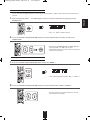
3. CONNECTING AUDIO COMPONENTS
• The TAPE IN/OUT jacks can be connected to audio recording equipment such as a tape deck, an MD recorder, etc.
• The AUX IN jacks can be connected to an additional components such as CD player, a tape deck, etc.
7
ENGLISH
■HDMI (High Definition Multimedia Interface) connection : ( )
RD-6504(A)_ENG:RD-6504(A)2009-02-12오 9:03페이지8
ENGLISH
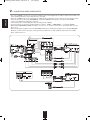
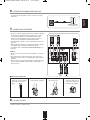
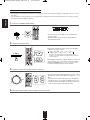
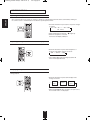
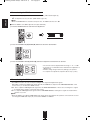
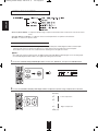
4. CONNECTING EXTERNAL INs
• Use these jacks to connect the corresponding analog
outputs of 6 CH decoder or DVD player with 6 CH output
for Dolby Digital or DTS, etc.
(For details, see the operator's manual of the component
to be connected.)
5. CONNECTING DIGITAL INs
• The OPTICAL and the COAXIAL DIGITAL OUTs of the
components that are connected to CD and VIDEO 1 ~
VIDEO 2 of this unit can be connected to these DIGITAL
INs.
• A digital input should be connected to the components
such as a CD player, LD player, DVD player, etc. capable
of outputting DTS Digital Surround, Dolby Digital or PCM
format digital signals, etc.
• For details, refer to the operating instructions of the
component connected.
• When making the COAXIAL DIGITAL connection, be sure
to use a 75 Ω COAXIAL cord, not a conventional AUDIO
cord.
• Some of the commercially available optical fiber cords
cannot be used for the equipment. If there is an optical
fiber cord which cannot be connected to your equipment,
consult your dealer or nearest service organization.
■Note :
• Be sure to make either a OPTICAL or a COAXIAL
DIGITAL connection on each component. (You don’t need
to do both.)
8
RD-6504(A)_ENG:RD-6504(A)2009-02-12오 9:03페이지9
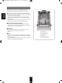
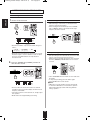
6. CONNECTING SUBWOOFER PRE OUT
ENGLISH
• To emphasize the deep bass sounds, connect a powered
subwoofer.
7. CONNECTING SPEAKERS
• Be sure to connect speakers firmly and correctly according to
the channel(left and right) and the polarity(+ and -). If the
connections are faulty, no sound will be heard from the
speakers, and if the polarity of the speaker connection is
incorrect, the sound will be unnatural and lack bass.
• For installing the speakers, refer to "Speaker placement" on
page 10.
• After installing the speakers, first adjust the speaker settings
according to your environment and speaker layout.
(For details, refer to "SETTING THE SPEAKER SETUP" on
page 34.)
Caution :
• Be sure to use the speakers with the impedance of 6 ohms or
above.
G
G
G
• Do not let the bare speaker wires touch each other or any
metal part of this unit. This could damage this unit and/or the
speakers.
• Never touch the speaker terminals while the AC input cord is
connected to the wall AC outlet. Doing so could result in
electric shocks.
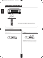
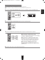
■Connecting speaker wire
1. Strip away approx. 10 mm
(3/8 inch) of wire insulation,
then twist the wire ends
tight.
2. Push the terminal lever,
then keep this condition.
3. Insert the bare part of the
wire into the hole.
8. AC INPUT CORD
• Plug the cord into a wall AC outlet.
9
4. Put the terminal lever
back, then make sure it
is fastened securely by
pulling the wire lightly.
RD-6504(A)_ENG:RD-6504(A)2009-02-12오 9:03페이지10
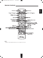
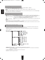
Speaker placement
ENGLISH
Ideal speaker placement varies depending on the size of your
room and the wall coverings, etc. The typical example of
speaker placement and recommendations are as follows :
■Front left and right speakers and center speaker
• Place the front speakers with their front surfaces as flush with
TV or monitor screen as possible.
• Place the center speaker between the front left and right
speakers and no further from the listening position than the
front speakers.
• Place each speaker so that sound is aimed at the location of
the listener’s ears when at the main listening position.
■Surround left and right speakers
• Place the surround speakers approximately 1 meter (40
inches) above the ear level of a seated listener on the direct
left and right of them or slightly behind.
■Subwoofer
• The subwoofer reproduces powerful deep bass sounds.
Place a subwoofer anywhere in the front as
desired.
■Notes :
• When using a conventional TV, to avoid interference with the
TV picture, use only magnetically shielded front left and right
and center speakers.
• To obtain the best surround effects, the speakers except the
subwoofer should be full range speakers.
10
1. TV or screen
2. Front left speaker
3. Front right speaker
4. Center speaker
5. Subwoofer
6. Surround left speaker
7. Surround right speaker
RD-6504(A)_ENG:RD-6504(A)2009-02-12오 9:03페이지11
ENGLISH
Front Panel Controls
1. POWER switch
2. POWER ON/STANDBY button
3. STANDBY indicator
4. FLUORESCENT DISPLAY
For details, see below.
5. VIDEO INPUT SELECTOR button
6. AUDIO INPUT SELECTOR button
7. EXT.IN SELECTOR button
8. BAND button
9. MASTER VOLUME CONTROL knob
10. MULTI CONTROL knob (◀/▶)
11. HEADPHONE jack
12. SPEAKER button/indicator
13. REMOTE SENSOR
14. SURROUND MODE button
15. STEREO button
16. DISPLAY button
17. DGITAL/ANALOG MODE button
18. SETUP button
19. CHANNEL LEVEL button
20. CONTROL UP/DOWN (▲/▼)
buttons
21. MEMORY/ENTER button
22. TUNING UP/DOWN (+/-) buttons
23. PRESET UP/DOWN (+/-) buttons
24. FRONT AUX jack
For details, see next page.
25. Bluetooth IN connector
For details, see next page.
■FLUORESCENT DISPLAY
1. Input, frequency, volume level, operating information, etc.
2. Surround mode indicators
3. AUTO indicator
4. DIGITAL INPUT indicator
5. DIRECT indicator
6. HDMI indicator
11
7. Preset number, sleep time display
8. MEMORY indicator
9. PRESET indicator
10. SLEEP indicator
11. TUNED indicator
12. STEREO indicator
RD-6504(A)_ENG:RD-6504(A)2009-02-12오 9:03페이지12
■ FRONT AUX JACK
ENGLISH
• The FRONT AUX jack can be connected to additional audio components such as an MP3 player, etc.
■ Note :
• When connecting this jack to an MP3 player, etc., you should use the stereo mini cord, not a mono mini cord.
■Bluetooth IN CONNECTOR
• If the Bluetooth IN connector is connected to Sherwood Audio
Receiver BT-R7(sold separately) with Bluetooth wireless technology,
you can enjoy music wirelessly with a music player featuring
Bluetooth wireless technology such as MP3 player, mobile phone,
etc..
(For information on Sherwood Audio Receiver BT-R7, contact your
dealer.)
• The Bluetooth word mark and logos are registered trademarks owned
by Bluetooth SIG, Inc. and any use of such marks by Sherwood
Corporation is under license. Other trademarks and trade names are
those of their respective owners.
■ Note :
• For safe operation, turn the power off before connecting or disconnecting the Audio Receiver BT-R7.
12
RD-6504(A)_ENG:RD-6504(A)2009-02-12오 9:03페이지13
ENGLISH
Remote Controls
■ Note :
• "VIDEO 3", "USB" and USB transport buttons are not available for this receiver.
13
RD-6504(A)_ENG:RD-6504(A)2009-02-12오 9:03페이지14
ENGLISH
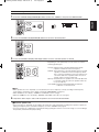
REMOTE CONTROL OPERATION RANGE
• Use the remote control unit within a range of about 7 meters (23
feet) and angles of up to 30 degrees aiming at the remote sensor.
LOADING BATTERIES
1. Remove the cover.
2. Load two batteries ("AAA" size, 1.5 V) matching the
polarity.
• Remove the batteries when they are not used for a
long time.
• Do not use the rechargeable batteries (Ni-Cd type).
14
RD-6504(A)_ENG:RD-6504(A)2009-02-12오 9:03페이지15
Operations
■Note : Before operating this receiver, first set this unit as desired for optimum performance, doing the system setup
procedures. (For details, refer to "System Setup" on page 29.)
ENGLISH
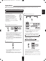
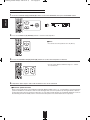
LISTENING TO A PROGRAM SOURCE
Before operation
• Enter the standby mode.
3. Select the desired input source.
• The STANDBY indicator lights up.
This means that the receiver is not
disconnected from the AC mains and a
small amount of current is retained to
support the operation readiness.
• To switch the power off, push the POWER
switch again.
• Then the power is cut off and the STANDBY
indicator goes off.
or
1. In the standby mode, turn the power on.
POW ER
or
• Each time the "VIDEO" button on the front panel is
pressed, the input source changes as follows:
VIDEO 1 ↔ VIDEO 2
• Each time the POWER ON/STANDBY button on the front
panel is pressed, the receiver is turned on to enter the
operating mode or off to enter the standby mode.
• On the remote control, press the POWER ON button to
enter the operating mode or press the STANDBY button
to enter the standby mode.
• In the standby mode, if the INPUT SELECTOR button is
pressed, the receiver is turned on automatically and the
desired input is selected.
• Each time the "AUDIO" button on the front panel is
pressed, the input source changes as follows:
→ CD →AUX → F. AUX → TAPE → BT IN
• Each time the "BAND" button is pressed, the band
changes as follows:
→ FM ST → FM MONO → AM
■When selecting the EXTERNAL IN as desired,
2. Switch the speakers on.
or
• "EXT IN" is displayed and 6 separate analog signals
from the component connected to this input pass
through the tone and the volume circuits only and can
be heard from your speakers.
• Select the desired input source to cancel the external in
function.
• These analog signals can be heard only, not recorded.
• Then the SPEAKER indicator lights up and the sound
can be heard from the speakers connected to the
speaker terminals.
• When using the headphone for private listening, press
the SPEAKER button again to switch the speakers off.
15
RD-6504(A)_ENG:RD-6504(A)2009-02-12오 9:03페이지16
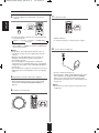
When CD, VIDEO 1~ 2 is selected as an input source
4. Select the digital or the analog input connected as
7. To mute the sound.
ENGLISH
desired.
or
• Each time this button is pressed, the corresponding input
is selected as follows:
→ o(ptical) → c(oaxial)1→ c(oaxial) 2 → H(HDMI audio)*
A(nalog) ←
• “MUTE” will flicker.
• To resume the previous sound level, press it again.
*: When VIDEO 1 or VIDEO 2 is selected, the HDMI audio
input can be selected.
8. To listen with the headphones.
■Notes :
• When AUX, F. AUX, TAPE, BT IN, EXT IN or tuner is
selected as an input source, the digital input cannot be
selected.
• When the selected digital input is not connected, the
"DIGITAL" indicator flickers and the analog input is
automatically selected.
• The selected digital or analog input is automatically
assigned to the corresponding input source on the INPUT
setup menu. (For details, refer to "SETTING THE INPUT "
on page 33.)
• The sound from the component connected to the selected
digital input can be heard regardless of the selected input
source.
• Be sure to switch the speakers off.
• When listening to a DTS or Dolby Digital program source,
if the headphones are plugged in and the SPEAKER
button is set to off, it enters the 2CH downmix mode
automatically. (For details, refer to "2CH downmix mode"
on page 19.)
5. Operate the selected component for playback.
• When playing back the program sources with surround
sound, refer to “ENJOYING SURROUND SOUND” on
page 19.
■Note :
• Be careful not to set the volume too high when using
headphones.
6. Adjust the (overall) volume.
or
DO WN
UP
16
RD-6504(A)_ENG:RD-6504(A)2009-02-12오 9:03페이지17
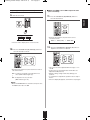
■When the TONE is set to ON to adjust the tone
(bass and treble).
Adjusting the tone (bass and treble)
9. Enter the tone mode.
11. Press the CURSOR UP(▲)/DOWN(▼) buttons to
ENGLISH
select the desired tone.
• Each time these buttons are pressed, the tone is
selected as follows :
→ BASS ↔ TRBL (treble) ↔ TONE: ON ←
• The tone mode is displayed for several seconds.
12. Press the CURSOR LEFT(◀)/RIGHT(▶) buttons to
adjust the selected tone as desired.
10. Press the CURSOR LEFT(◀)/RIGHT(▶) buttons to
select the desired tone mode.
• The tone level can be adjusted within the range of -12 ~
+12 dB.
• In general, we recommend the bass and treble to be
adjusted to 0 dB (flat level).
• Extreme settings at high volume may damage your
speakers.
• To complete tone adjustment, repeat the above steps 11
and 12.
• If the tone display disappears, start from the step 9 again.
• Each time these buttons are pressed, the tone mode is
selected as follows :
OFF : To listen to a program source without the tone
effect. ("DIR" indicator lights up.)
↕
ON : To adjust the tone for your taste.
("DIR" indicator goes off.)
■Note :
• When the EXTERNAL IN is selected as an input source,
the TONE cannot be set to ON.
17
RD-6504(A)_ENG:RD-6504(A)2009-02-12오 9:03페이지18
SURROUND SOUND
ENGLISH
• This receiver incorporates a sophisticated Digital Signal Processor that allows you to create optimum sound quality and sound
atmosphere in your personal Home Theater.
Surround modes
■DTS Digital Surround
• The following modes apply conventional 2-channel
signals such as digital PCM or analog stereo signals to
high performance Digital Signal Processor to recreate
sound fields artificially.
DTS Digital Surround(also called simply DTS) is a multichannel digital signal format which can handle higher data
rates. Discs bearing the DTS logo include the recording of
up to 5.1 channels of digital signals, which can be generally
thought to provide better sound quality due to the lower
audio compression required.
It also provides wide dynamic range and separation,
resulting in magnificent sound.
■Virtual Surround 2 Speaker
This mode creates a virtual surround sound field using as
few as two front speakers, allowing you to experience
listening from 5.1 channel speakers.
This mode is effective not only for 5.1 channel sources but
also for 2 channel sources.
■DTS 96/24
This is high resolution DTS with a 96 kHz sampling rate
and 24 bit resolution, providing superior fidelity. Use it with
DVDs bearing the DTS 96/24 logo.
■Virtual Surround 3 Speaker
This mode creates a virtual surround sound field using two
front and one center speakers, allowing you to experience
listening from 5.1 channel speakers. This mode is effective
only for 5.1 channel sources.
Manufactured under license under U.S. Patent #'s: 5,451,942;
5,956,674; 5,974,380; 5,978,762; 6,226, 616; 6,487,535 & other U.S.
and worldwide patents issued & pending. DTS and DTS Digital
Surround are registered trademarks and the DTS logos , Symbol and
DTS 96/24 are trademarks of DTS, Inc. ⓒ1996-2008 DTS, Inc. All
Rights Reserved.
■Big Hall/Bright Hall/Dark Hall
These modes provide the ambience of a concert hall for
classical music sources such as orchestral, chamber
music, or an instrumental solo.
■Dolby Digital
■Cathedral
Dolby Digital is the multi-channel digital signal format
developed by Dolby Laboratories. Discs bearing the Dolby
Digital logo includes the recording of up to 5.1 channels of
digital signals, which can reproduce much better sound
quality, spatial expansion and dynamic range
characteristics than the previous Dolby Surround effect.
This mode provides the ambience of a cathedral for
baroque, string orchestral or choral group music.
■Club/Bright Club/Smoky Club
These modes provide the ambience of a live house for jazz
music, vocals and acoustical instrumental sounds.
■Dolby Pro Logic II surround
This mode applies conventional 2-channel signals such as
digital PCM or analog stereo signals as well as Dolby
Surround signals, etc. to surround processing to offer
improvements over conventional Dolby Pro Logic circuits.
Dolby Pro Logic ll surround includes 3 modes as follows:
■Bright Stadium
This mode provides the expansive sound field to achieve
the true stadium effect when watching baseball or soccer
games.
■Arena
• Dolby Pro Logic ll MOVIE
When enjoying movies, this mode allows you to further
enhance the cinematic quality by adding processing that
emphasizes the sounds of the action special effects.
This mode provides a dynamic and broad sound space to
heighten the overall impact of the sound track.
■Vox Cinema/Music Cinema
• Dolby Pro Logic ll MUSIC
When listening to music, this mode allows you to further
enhance the sound quality by adding processing that
emphasizes the musical effects.
When listening to movie, select the Vox Cinema mode to
enhance the clarity of the dialog or select the Music
Cinema mode to enhance the musical effects.
• Dolby Pro Logic ll Emulation
This mode expands any 2-channel sources(, including
Dolby Surround sources) for 4 channel(front left, center,
front right and surround) playback.
The surround channel is monaural, but is played through
two surround speakers.
This mode is for enjoying stereo sound from all speakers.
■5CH Stereo
■Virtual Surround Headphone
This mode simulates 5.1 channel surround sound, which
allows you to enjoy 5.1 channel surround sound through 2
channel headphone, just like listening from 5.1 channel
speakers. This mode effective not only 5.1 channel sources
but also for 2 channel sources.
Dolby, Pro Logic, and the double-D symbol are registered
trademarks of Dolby Laboratories.
• When the EXTERNAL INs is connected to the 6CH decoder for a surround sound such as Dolby Digital, etc., you can enjoy
the corresponding surround sound, too. (For details, see the operator's manual of the component to be connected.)
18
RD-6504(A)_ENG:RD-6504(A)2009-02-12오 9:03페이지19
ENJOYING SURROUND SOUND
■When CD or VIDEO 1 ~ 2 is selected as an input source
Select the auto surround mode or the manual surround mode depending on how to select a surround mode.
• Each time this button is pressed, the mode changes as follows :
Auto surround mode : The optimum surround mode will be automatically
("AUTO" indicator
selected depending on the signal format being input.
lights up.)
Manual surround mode : You can select the desired of different surround
modes selectable for the signal being input with
("AUTO" indicator
goes off.)
using the MULTI CONTROL knob or the
SURROUND MODE UP/DOWN (>/<) buttons.
■Notes :
• When the input source other than CD and VIDEO 1 ~ 2 is selected, you cannot select the auto surround mode and can select
the surround mode as desired (the manual surround mode).
• When the auto surround mode is selected, the surround modes other than the optimum surround mode cannot be selected.
■Select the desired surround mode (when selecting the manual surround mode in case of CD, VIDEO 1 ~ 2)
• Each time the MULTI CONTROL knob is rotated or the
SURROUND UP / DOWN (>/<) buttons are pressed, the
surround mode changes depending on the input signal
format as follows :
Selectable surround mode
Signal format being input
Dolby Digital 5.1 channel sources
DOLBY DIGITAL, VS 2 SPK, VS 3 SPK
Dolby Digital 2 channel sources
DOLBY PLII MOVIE, DOLBY PLII MUSIC, DOLBY PLII EMULATION, VS 2 SPK
DTS sources, DTS 96/24 sources
corresponding DTS mode, VS 2 SPK, VS 3 SPK
PCM (2channel) sources,
DOLBY PLII MOVIE, DOLBY PLII MUSIC, DOLBY PLII EMULATION, VS 2 SPK, BIG HALL,
Analog stereo sources
BRIGHT HALL, DARK HALL, CATHEDRAL, CLUB, BRIGHT CLUB, SMOKY CLUB, BRIGHT
STADIUM, ARENA, VOX CINEMA, MUSIC CINEMA, 5CH STEREO
96 kHz PCM(2 channel) sources,
DOLBY PLII MOVIE, DOLBY PLII MUSIC, DOLBY PLII EMULATION
■To cancel the surround mode for stereo playback
• Depending on the signal format which is being input,
either the stereo mode or the 2CH downmix mode is
selected.
• To cancel either the stereo mode or the 2CH downmix
mode, select the surround mode with using the MULTI
CONTROL knob on the front panel or the SURROUND
MODE UP/DOWN (>/<) buttons on the remote control.
or
■2CH downmix mode
• This mode allows the multi-channel signals encoded in DTS or Dolby Digital format to be mixed down into 2 front channels
and to be reproduced through only two front speakers or through headphones.
• When the SPEAKER button is set to off to listen with headphones while playing the multi-channel digital signals from DTS or
Dolby Digital sources, it can enter the 2CH downmix mode automatically.
19
ENGLISH
■Notes:
• Before surround playback, first perform the speaker setup procedure, etc. on the SETUP menu for optimum performance. (For
details, refer to "SETTING THE SPEAKER SETUP" on page 34.)
• When the EXTERNAL IN is selected as an input source, the surround modes cannot be selected.
RD-6504(A)_ENG:RD-6504(A)2009-02-12오 9:03페이지20
Listening in Virtual Surround Headphone mode
ENGLISH
• The Virtual Surround Headphone mode simulates 5.1 channel surround, which allows you to enjoy 5.1 channel surround
sound through 2 channel hedphones, just like listening from 5.1 channel speakers.
■Note :
• Only when the SPEAKER button is set to off, the Virtual Surround Headphone mode can be selected.
• Select the Virtual Surround Headphone mode.
• Then "VS HP" is displayed and the Virtual Surround
Headphone mode is selected.
• To cancel the Virtual Surround Headphone mode, press
the STEREO button.
When adjusting the sound parameters
• While playing digital signals from Dolby Digital or DTS program source or listening in Dolby Pro Logic II Music mode, you
can adjust their parameters for optimum surround effect.
1. Press the SOUND PARAMETER button.
• Then "DRC : ~ " (or "PANO : ~ ") is displayed for several
seconds.
• If the parameter mode disappears, press this button again.
2. Press the CURSOR UP(▲)/DOWN(▼) buttons to select the desired parameter.
• Each time these buttons are pressed, the parameter mode
changes as follows:
→ "DRC"
↔ "PANO" ↔ "C.WIDTH" ↔ "DIMEN" ←
(Dynamic Range Compression) (Panorama mode) (Center width control) (Dimension control)
• "DRC" can be selected only while playing digital signals
from Dolby Digital or DTS source.
• "PANO", "C.WIDTH" and "DIMEN" can be selected only
while listening in Dolby Pro Logic II Music mode.
3. Press the CURSOR LEFT(◀)/ RIGHT(▶) buttons to adjust the selected parameter as desired.
■When selecting the "DRC (Dynamic Range Compression :
Night mode)"
This function compresses the dynamic range of previously
specified parts of Dolby Digital or DTS sound track (with extremely
high volume) to minimize the difference in volume between the
specified and non-specified parts. This makes it easy to hear all of
the sound track when watching movies at night at low levels. The
night mode can be set in 11 steps from OFF(0.0) to MAX(1.0)
(default value : OFF(0.0)).
■Note :
• In some Dolby Digital or DTS softwares, the night mode may not
be valid.
20
RD-6504(A)_ENG:RD-6504(A)2009-02-12오 9:03페이지21
continued
■When selecting the "C. WIDTH (Center width)" control
This adjusts the center image so it may be heard only from the center speaker, only from the left/right speakers as a phantom
image, or from all three front speakers to varying degrees.
The control can be set in 8 steps from 0 to 7(default value : 3).
■When selecting the "DIMEN (Dimension)" control
This gradually adjusts the soundfield either towards the front or towards the rear. The control can be set in 7 steps from -3 to
+3 (default value : 0).
4. Repeat the above steps 2 and 3 to adjust other parameters.
Adjusting each channel level with test tone
• The volume level of each channel can be adjusted easily with the test tone function.
1. Enter the test tone mode.
• The test tone mode is displayed and will be heard from
the speaker of each channel for 2 seconds as follows:
→ FL → C → FR → SR → SL → SW
Front Left
Center
Front Right
Surround Right
Surround Left
Subwoofer
• When the speaker setting is "N (None or No)", the test
tone of the corresponding channel is not available.
■Notes :
※ The test tone function does not work as expected if :
• The SPEAKER button is set to off.
• EXTERNAL IN is selected as an input source.
• It is in the stereo or the 2CH downmix mode.
2. At each channel, adjust the level as desired until the sound level of each speaker is heard to be equally loud.
• You can select the desired channel with the CONTROL
UP(▲)/DOWN(▼) buttons or the CURSOR UP(▲)/
DOWN(▼) buttons.
3. Cancel the test tone function.
21
ENGLISH
■When selecting the "PANO (Panorama)" mode
This mode extends the front stereo image to include the surround speakers for an exciting "wraparound" effect with side wall
imaging.
Select "OFF" or "ON"(default value: OFF).
RD-6504(A)_ENG:RD-6504(A)2009-02-12오 9:03페이지22
Adjusting the current channel level
ENGLISH
• After adjusting each channel level with test tone, adjust the channel levels either according to the program sources or to suit
your tastes.
• You can adjust the current channel levels as desired. These adjusted levels are just memorized into user’s memory ("CAL"),
not into preset memory("REF 1", "REF 2").
1. Press the CHANNEL LEVEL button.
or
• Then the memory mode ("REF 1", etc.) is displayed for
several seconds.
• When the memory mode or channel level disappears,
press this button again.
2. Select the desired channel.
• Each time these buttons are pressed, the corresponding
channel is selected as follows:
→ REF 1, 2 (or CAL) ↔ FL ↔ C ↔ FR ←
→ <DTS or DD> ↔ SW ↔ SL ↔ SR ←
< >: Only when the digital signals from Dolby Digital or DTS
program sources that include LFE signal are input, LFE level
can be displayed.
• Depending on the speaker settings ("N (None or No)") and
surround mode, etc., some channels cannot be selected.
• When the SPEAKER button is set to off, only the Front
Left and Front Right channels can be selected.
3. Adjust the level of the selected channel as desired.
• The LFE level can be adjusted within the range of -10~0
dB and other channel levels within the range of -15 ~ +15
dB.
• In general, we recommend the LFE level to be adjusted
to 0 dB. (However, the recommended LFE level for some
early DTS software is -10 dB.) If the recommended levels
seem too high, lower the setting as necessary.
4. Repeat the above steps 2 and 3 to adjust each channel level.
22
RD-6504(A)_ENG:RD-6504(A)2009-02-12오 9:03페이지23
Memorizing the adjusted channel levels
• You can memorize the adjusted channel levels into preset memory("REF 1", "REF 2") and recall the memorized whenever you
want.
ENGLISH
1. After performing the steps 1 ~ 4 in "Adjusting the current channel level" procedure on page 22, press the
(MEMORY/)ENTER button.
or
• Then "1" of "REF 1" indication flickers for several
seconds.
2. Select the desired one of REF 1 and REF
2.
• If the preset memory disappears, perform the above
step 1 again.
3. Confirm your selection.
• The adjusted channel levels have now been memorized
into the selected memory.
or
Recalling the memorized channel levels
1. Press the CHANNEL LEVEL button.
• "CAL " (or "REF 1", etc.) is displayed for several
seconds.
• If the channel level mode display disappears, press this
button again.
or
2. Select the desired one of REF 1 and REF 2.
• Then the channel levels memorized into the selected
preset memory are recalled.
23
RD-6504(A)_ENG:RD-6504(A)2009-02-12오 9:03페이지24
LISTENING TO RADIO BROADCASTS
ENGLISH
Auto tuning
1. Select the desired band.
Manual tuning
• Manual tuning is useful when you already know the
frequency of the desired station.
• After selecting the desired band, press the TUNING
UP(+) / DOWN(-) buttons repeatedly until the right
frequency has been reached.
or
• Each time this button is pressed, the band changes as
follows ;
→ FM ST → FM MONO → AM
("ST" lights up)
("ST" goes off)
Auto presetting
• When FM stereo broadcasts are poor because of weak
broadcast signals, select the FM mono mode to reduce
the noise, then FM broadcasts are reproduced in
monaural sound.
• Auto presetting function automatically searches for FM
stations only and stores them in the memory.
• While listening to FM radio broadcasts, press and hold
down the (MEMORY/) ENTER button for more than 2
seconds.
2. Press the TUNING UP(+)/DOWN(-) buttons for
more than 0.5 second.
or
• Then "AUTO MEM" flickers and this receiver starts auto
presetting.
• To stop auto presetting, press this button again.
• Up to 30 FM stations can be stored.
■Notes:
• FM stations of weak strength cannot be memorized.
• To memorize AM stations or weak stations, preform
"Manual presetting" procedure with using "Manual
tuning" operation.
• The tuner will now search until a station of sufficient
strength has been found. The display shows the tuned
frequency and "TUNE".
• If the station found is not the desired one, simply repeat
this operation.
• Weak stations are skipped during auto tuning.
24
RD-6504(A)_ENG:RD-6504(A)2009-02-12오 9:03페이지25
Manual presetting
Tuning to preset stations
• You can store up to 30 preferred stations in the memory.
• After selecting the tuner as an input source, select the
desired preset number.
tuning.
2. Press the (MEMORY/)ENTER button.
or
• When using the NUMERIC buttons on the remote control.
Examples) For “3” :
For “15” :
MEM
For “30” :
• "MEM" is flickering for several seconds.
3. Select the desired preset number (1~30) and
press the (MEMORY/)ENTER button.
• When using the NUMERIC buttons on the remote
control.
Examples) For “3” :
For “15” :
For “30” :
• The station has now been stored in the memory.
• When using the NUMERIC buttons, the station is stored
automatically without pressing the (MEMORY/)ENTER
button.
• A stored frequency is erased from the memory by
storing another frequency in its place.
• If “MEM” goes off, start again from the above step 2.
4. Repeat the above steps1 to 3 to memorize other
stations.
■MEMORY BACKUP FUNCTION
The following items, set before the receiver is turned off,
are memorized.
• INPUT SELECTOR settings
• Surround mode settings
• Preset stations,etc.
25
ENGLISH
1. Tune in the desired station with auto or manual
RD-6504(A)_ENG:RD-6504(A)2009-02-12오 9:03페이지26
ENGLISH
RECORDING
• The analog signals from the EXTERNAL INs as well as the digital signals from the coaxial, optical digital input or HDMI IN
can be heard but cannot be recorded.
• When recording the analog signals from CD, VIDEO 1 ~ 2, be sure to select th analog input.
(For details, refer to "When CD, VIDEO 1 ~ 2 is selected as an input source" on page 16.)
• The volume and tone (bass, treble) settings have no effect on the recording signals.
Recording with TAPE
1. Select the desired input as a recording source except for TAPE.
or
2. Start recording on the TAPE.
3. Start play on the desired input.
Dubbing from video components onto VIDEO 1
1. Select VIDEO 2 as a recording source.
or
2. Start recording on the VIDEO 1.
3. Start play on the VIDEO 2.
• The audio and video signals from the VIDEO 2 will be dubbed onto the VIDEO 1 and you can enjoy them on the TV set and
from the speakers.
26
RD-6504(A)_ENG:RD-6504(A)2009-02-12오 9:03페이지27
Dubbing the audio and video signals separately onto VIDEO 1
Example) When dubbing the VIDEO 2 video signal and the CD audio signal separately onto VIDEO 1.
ENGLISH
1. Select VIDEO 2 as a video recording source.
or
2. Select CD as an audio recording source.
or
3. Start recording on the VIDEO 1.
4. Start play on the VIDEO 2 and the CD respectively.
• The audio signal from the CD and the video signal from the VIDEO 2 will be dubbed and you can enjoy them on the TV set
and from the speakers.
■Note :
• Be sure to observe the order of the above steps 1 and 2.
27
RD-6504(A)_ENG:RD-6504(A)2009-02-12오 9:03페이지28
OTHER FUNCTIONS
ENGLISH
Operating the sleep timer
• The sleep timer allows the system to continue to operate for a specified period of time before automatically shutting off.
• To set the receiver to automatically turn off after the specified period of time.
• Each time this button is pressed, the sleep time changes
as follows:
→ 10 → 20 → 30 → --- → 90 → OFF
Unit : minutes
• While operating the sleep timer, "
• When the sleep time is selected,
the fluorescent display is dimly lit.
" lights up.
Adjusting the brightness of the fluorescent display
• Each time this button is pressed, the brightness of
the fluorescent display changes as follows:
→ ON → dimmer → OFF
• In the display OFF mode, pressing any button will
restore the display ON mode.
Displaying the operation status
During playback,
• Each time this button is pressed, the display mode
changes as follows:
→
Surround
mode
→
Volume
→
Input
source
• When the EXTERNAL IN is selected as an input source,
the surround mode is not displayed.
28
RD-6504(A)_ENG:RD-6504(A)2009-02-12오 9:03페이지29
System Setup
■Navigating through the setup menu
• The explanations here assume you are using the buttons on the remote control when performing the setup menu operation.
However, you can use the buttons on the front panel as well.
The buttons on the front panel correspond to those on the remote control as shown below.
1. Turn the setup menu on.
• The setup menu will be shown.
• To turn the menu off, press this button again.
2. Select the desired menu using the CURSOR UP(▲)/DOWN(▼) buttons.
3. Confirm your selection.
• When selecting "SYSTEM", see "SETTING THE
SYSTEM" on page 31.
• When selecting "INPUT", see "SETTING THE
INPUT" on page 33.
• When selecting "SPK SET", see "SETTING THE
SPEAKER SETUP" on page 34.
• When selecting "CH LEVEL", see "SETTING
THE CH LEVEL" on page 38.
• When selecting "PARAMTR", see "SETTING
THE PARAMETER" on page 40.
• When selecting "EXIT", the setup menu will be
turned off.
29
ENGLISH
• The setup menu is displayed on the fluorescent display and allows you to perform the setup procedures easily. In most situations,
you will only need to set this once during the installation and layout of your home theater, and it rarely needs to be changed later.
The setup menu consists of 5 main menus ; system, input, speaker setup, CH level and parameter. These menus are then divided
up into various sub-menus.
RD-6504(A)_ENG:RD-6504(A)2009-02-12오 9:03페이지30
ENGLISH
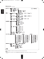
■Setup menu flow
• The setup menu flow is as follows :
• When "RETURN" is selected on a sub-menu, it will returns to the previous menu.
■Note :
• During setup menu operation, only the (POWER ON/) STANDBY button and the buttons required for system setup will
function.
30
RD-6504(A)_ENG:RD-6504(A)2009-02-12오 9:03페이지31
ENGLISH
SETTING THE SYSTEM
• SW (SUBWOOFER) : To select the desired subwoofer mode.
• TONE : To adjust the tone (bass and treble) as desired.
• HDMI : To output the digital audio signals from the HDMI MONITOR OUT connector.
• RETURN : To return to the previous menu.
1. Press CURSOR UP(▲)/DOWN(▼) buttons to select the desired item.
2. Press the CURSOR LEFT(◀)/RIGHT(▶) buttons to set the selected item as desired.
When selecting the SUBWOOFER mode
• "SW +" mode is effective only when "FRONT" is set to "L" and "SUB- W" is set to "Y" on the SPK SET menu. (For details,
refer to "SETTING THE SPEAKER SETUP" on page 34.)
NORM : When the low frequency signals of channels set to "L" are reproduced from those channels only.
In this mode, the low frequency signals that are reproduced from the subwoofer channel is only the low frequency
signals of LFE (from the multi-channel sources that contains LFE (Low Frequency Effects) channel, also called the
".1" channel) and the channels set to "S".
SW +: When the low frequency signals of channels set to "L" are reproduced simultaneously from those channels and the
subwoofer channel.
In this mode, the low frequency range expands more uniformly through the room, but depending on the size and
shape of the room, interference may result in a decrease of the actual volume of the low frequency range.
31
RD-6504(A)_ENG:RD-6504(A)2009-02-12오 9:03페이지32
ENGLISH
When selecting the TONE
OFF : To listen to a program source without the tone effect. ("DIR" indicator lights up.)
↕
ON : To adjust the tone for your taste. ("DIR" indicator goes off.)
■Note :
• When the EXTERNAL IN is selected as an input source, the TONE cannot be set to ON.
■When the TONE is set to ON to adjust the tone (bass and treble)
①Press the ENTER button to enter the tone adjustment.
②Press the CURSOR UP(▲)/DOWN(▼) buttons to select the desired tone.
③Press the CURSOR LEFT(◀)/RIGHT(▶) buttons to adjust the selected tone as desired.
• The tone level can be adjusted within the range of -12 ~ +12 dB.
• In general, we recommend the bass and treble to be adjusted to 0
dB (flat level).
• Extreme settings at high volume may damage your speakers.
• To complete tone adjustment, repeat the above steps ② and ③.
When selecting the HDMI
• The HDMI connection can carry uncompressed digital video signals and digital audio signals.
Depending on whether the digital audio signals input into the HDMI IN are output from the HDMI MONITOR OUT of this
receiver or not, you should set the HDMI correctly.
OFF : Not to output the HDMI digital audio signals from the HDMI MONITOR OUT of this receiver, meaning these signals
↕ are heard from the speakers connected to this receiver.
ON : To output the HDMI digital audio signals from the HDMI MONITOR OUT, meaning these signals are heard from the
speakers of your TV.
■Note:
• When the HDMI is set to ON, the HDMI digital audio signals will not be heard from the speakers connected to this receiver
even though the HDMI audio input ("H") is selected for VIDEO 1 or VIDEO 2.
32
RD-6504(A)_ENG:RD-6504(A)2009-02-12오 9:03페이지33
ENGLISH
SETTING THE INPUT
: The HDMI audio input can be selected on the VIDEO 1 or VIDEO 2 configuration menu only.
• D.IN (DIGITAL IN) : To assign the connected DIGITAL INs to the desired input.
• AUTO (AUTO SURROUND) : To select the auto surround mode or the manual surround mode.
• RETURN : To return to the previous menu.
■Note :
• In such a case that the HDMI IN is connected to your video component at the very first, the HDMI audio input is automatically
assigned to the input source (VIDEO 1 or VIDEO 2).
1.
Press the CURSOR UP(▲)/DOWN(▼) buttons to select the desired input source, then press the ENTER
button.
Example) When selecting the CD
2. Press the CURSOR UP(▲)/DOWN(▼) buttons to select the desired item.
3. Press the CURSOR LEFT(◀)/RIGHT(▶) buttons to set the selected item as desired.
33
RD-6504(A)_ENG:RD-6504(A)2009-02-12오 9:03페이지34
ENGLISH
When selecting the DIGITAL IN
• You should assign the connected DIGITAL INs to the desired of CD and VIDEO 1 ~ VIDEO 2.
(For details, refer to "CONNECTING DIGITAL INs" on page 8.)
• You can select the desired of OPT (optical), COX 1(coaxial 1), COX 2(coaxial 2) (, HDMI) and ANL (analog).
■Note :
• In such a case that a DIGITAL IN is assigned to two input sources or more, when these input sources are selected, the digital
audio signals can be heard from the same DIGITAL IN.
When selecting the AUTO SURROUND
• Depending on how to select a surround mode, you can select the auto surround mode or the manual surround mode.
OFF
: You can select the desired of different surround modes selectable for the signal being input with
(Manual surround mode) using the MULTI CONTROL knob or the SURROUND MODE UP/DOWN (>/<) buttons.
↕
(For details, refer to "ENJOYING SURROUND SOUND" on page 19.)
ON
: The optimum surround mode will be automatically selected depending on the signal format being
(Auto surround mode)
input.
■Notes :
• When the input source other than CD and VIDEO 1 ~ 2 is selected, you cannot select the auto surround mode and can
select the surround mode as desired(the manual surround mode).
• When the auto surround mode is selected, the surround modes other than the optimum surround mode cannot be selected.
SETTING THE SPEAKER SETUP
• After you have installed this receiver and connected all the components, you should adjust the speaker settings for the
optimum sound acoustics according to your environment and speaker layout.
• Even when you change speakers, speaker positions, or the layout of your listening environment, you should adjust the
speaker settings, too.
• CONFIG (CONFIGURATION) : To select the sizes of the speakers that are connected.
• DISTANCE: To enter the distance between the listening position and each speaker to set the delay time automatically for
optimum surround playback.
• X-OVER (CROSSOVER) : To select the desired crossover frequency.
• RETURN : To return to the previous menu.
34
RD-6504(A)_ENG:RD-6504(A)2009-02-12오 9:03페이지35
When selecting the CONFIGURATION
ENGLISH
1. Press the CURSOR UP(▲)/DOWN(▼) buttons to select the "CONFIG", then press the ENTER button.
2. Press the CURSOR UP(▲)/DOWN(▼) buttons to select the desired speaker.
3. Press the CURSOR LEFT(◀)/ RIGHT(▶) buttons to set the selected speaker as desired.
• Depending on your speaker type, you can select one of these
following speaker types.
L(Large): Select this when connecting speakers that can fully
reproduce sounds below crossover frequency.
S(Small) : Select this when connecting speakers that can not fully
reproduce sounds below crossover frequency. When
this is selected, sounds below crossover frequency are
sent to the subwoofer or speakers which are set to "L
(Large)" (when not using a subwoofer)
N(None): Select this when no speakers are connected. When this
is selected, sounds are sent to the speakers which are
not set to "N (None)".
Y(Yes)/N(No): Select the desired depending on whether a
subwoofer is connected or not.
■Notes :
• When speakers are set to "S (Small)", you should set their crossover frequency correctly according to their frequency
characteristics. (For details, refer to "When selecting the CROSSOVER" on page 37.)
• When "SUB-W" is set to "N (No)", "FRONT" is automatically set to "L (Large)".
• When the "FRONT" is set to "S (Small)", "CENTER" and "SURR" cannot be set to "L (Large)".
4. Repeat the above steps 2 and 3 until the speakers are all set to the desired mode.
■About the speaker size
• Select "L (Large)" or "S (Small)" not according to the actual size of the speaker but according to the speaker's capacity for
playing low frequency (bass sound below frequency set on the "X-OVER" menu) signals.
• If you do not know, try comparing the sound at both settings (setting the volume to a level low enough so as not to damage
the speakers) to determine the proper setting.
35
RD-6504(A)_ENG:RD-6504(A)2009-02-12오 9:03페이지36
When selecting the DISTANCE
button.
ENGLISH
1. Press the CURSOR UP(▲)/DOWN(▼) buttons to select the DISTANCE, then press the ENTER
2. Press the CURSOR UP(▲)/DOWN(▼) buttons to select the desired speaker.
■Note :
• You cannot select the speakers set to "N (None)".
3. Press the CURSOR LEFT(◀)/RIGHT(▶) buttons to set the selected speaker as desired.
• You can set the distance within the range of 1 ~ 30 feet
in 1 feet intervals.
4. Repeat the above steps 2 and 3 until the distances are all set as desired.
■About the speaker distance
When enjoying multi-channel surround playback with Dolby Digital and DTS sources, etc., it is ideal that the center and surround
speakers should be the same distance from the main listening position as the front speakers. By entering the distance between
the listening position and each speaker, the delay times of center and surround speakers are automatically adjusted to create an
ideal listening environment virtually as if the center and surround speakers were at their ideal locations respectively.
36
RD-6504(A)_ENG:RD-6504(A)2009-02-12오 9:03페이지37
When selecting the CROSSOVER
1. Press the CURSOR UP(▲)/DOWN(▼) buttons to select the "X-OVER", then press the ENTER button.
2. Press the CURSOR LEFT(◀)/RIGHT(▶) buttons to set the crossover frequency as desired.
• You can adjust the crossover frequency within the
range of 40 ~ 200 Hz in 10 Hz intervals.
■About the crossover frequency
• When speakers are set to "S (Small)", low frequencies in those channels that are below the crossover frequency are to
output from subwoofer or front speakers which are set to "L (Large)" (when not using a subwoofer).
• Refer to the operating instructions of the speakers to be connected. If the frequency range of your speaker is 100 Hz~20
kHz, the crossover frequency should be set to 100 Hz(or slightly higher).
37
ENGLISH
• When speakers are set to "S (Small)", be sure to set their crossover frequency correctly according to their frequency
characteristics.
RD-6504(A)_ENG:RD-6504(A)2009-02-12오 9:03페이지38
ENGLISH
SETTING THE CH LEVEL
■Note : Depending on the speaker settings ("N (None or No)"), some channels cannot be selected.
Adjusting the current channel level
• You can adjust the current channel levels as desired. These adjusted levels are just memorized into user’s memory("CAL"),
not into preset memory ("REF 1", "REF 2")
• After adjusting each channel level with test tone, adjust the channel levels either according to the program sources or to suit
your tastes. (For details, refer to "Adjusting each channel level with test tone" on page 21.)
1. Press the CURSOR UP(▲)/DOWN(▼) buttons to select the desired channel.
Example) When selecting Dolby Digital source's LFE
2. Press the CURSOR LEFT(◀)/RIGHT(▶) buttons to adjust the level of the selected channel or
program
source's LFE as desired.
• The LFE level can be adjusted within the range of -10 ~ 0
dB and other channel levels within the range of -15 ~ +15 dB
• In general, we recommend the LFE level to be adjusted to
0 dB. (However, the rcommended LFE level for some
early DTS software is -10 dB.) If the recommended levels
seem too high, lower setting as necessary.
3. Repeat the above steps 1 and 2 to adjust each channel level.
38
RD-6504(A)_ENG:RD-6504(A)2009-02-12오 9:03페이지39
Memorizing the adjusted channel levels
• You can memorize the adjusted channel levels into preset memory("REF 1", "REF 2") and recall the memorized whenever
you want.
1. After performing the steps 1 ~ 3 in "Adjusting the current channel level" procedure on page 38, press the
ENGLISH
ENTER button.
• Then "1" of "REF 1" indication flickers.
2. Press the CURSOR LEFT(◀)/RIGHT(▶) buttons to select the desired preset memory, then press the
ENTER button.
• Each time the CURSOR LEFT(◀) or RIGHT(▶) button
is pressed, "REF 1" or "REF 2" is selected.
• The adjusted channel levels have now been memorized
into the selected memory.
Recalling the memorized channel levels
1. Press the CURSOR UP(▲)/DOWN(▼) buttons to select the "MODE ~ ".
• "CAL" may be displayed instead of "REF 1" or "REF 2".
2. Press the CURSOR LEFT(◀)/RIGHT(▶) buttons to select the desired one of REF 1 and REF 2.
• Then the channel levels memorized into the selected
preset memory are recalled.
39
RD-6504(A)_ENG:RD-6504(A)2009-02-12오 9:03페이지40
ENGLISH
SETTING THE PARAMETER
• NIGHT M (NIGHT MODE) : To adjust the dynamic range compression that makes faint sound easier to hear at low volume
levels.
• PLII MSC (DOLBY PLII MUSIC) : To adjust the various surround parameters for optimum surround effect.
• RETURN : To return to the previous menu.
When selecting the NIGHT MODE
• This function compresses the dynamic range of previously specified parts of Dolby Digital or DTS sound track (with
extremely high volume) to minimize the difference in volume between the specified and non-specified parts.
This makes it easy to hear all of the sound track when watching movies at night at low levels.
■Notes:
• The night mode setting is valid only when the digital signals from Dolby Digital or DTS program source are being input.
• In some Dolby Digital or DTS softwares, the night mode setting may not be valid.
1. Press the CURSOR UP(▲)/DOWN(▼) buttons to select the "NIGHT M", then press the ENTER button.
2. Press the CURSOR LEFT(◀)/ RIGHT(▶) buttons to adjust the dynamic range compression as desired.
OFF (0.0)
↕
0.1
↕
0.2
:
:
:
0.9
↕
MAX (1.0)
40
Lower compression
Higher compression
RD-6504(A)_ENG:RD-6504(A)2009-02-12오 9:03페이지41
When selecting the DOLBY PLII MUSIC
1. Press the CURSOR UP(▲)/DOWN(▼) buttons to select the "PLII MSC", then press the ENTER
button.
2. Press the CURSOR UP(▲)/DOWN(▼) buttons to select the desired parameter.
3. Press the CURSOR LEFT(◀)/ RIGHT(▶) buttons to adjust the selected parameter as desired.
■When selecting the "PANO (Panorama)" mode
This mode extends the front stereo image to include the surround
speakers for an exciting "wraparound" effect with side wall imaging.
Select "OFF" or "ON"(default value:OFF).
■When selecting the "C. WIDTH (Center width)" control
This adjusts the center image so it may be heard only from the
center speaker, only from the left/right speakers as a phantom
image, or from all three front speakers to varying degrees. The
control can be set in 8 steps from 0 to 7 (default value : 3).
■When selecting the "DIMEN (Dimension)" control
This gradually adjusts the soundfield either towards the front or
towards the rear. The control can be set in 7 steps from -3 to +3
(default value : 0).
4. Repeat the above steps 2 and 3 to adjust other parameters.
41
ENGLISH
• You can adjust the various surround parameters for optimum surround effect.
■Note: The parameter settings are valid only when listening in Dolby Pro Logic II Music mode.
RD-6504(A)_ENG:RD-6504(A)2009-02-12오 9:03페이지42
ENGLISH
Troubleshooting Guide
If a fault occurs, run through the table below before taking your receiver for repair.
If the fault persists, attempt to solve it by switching the receiver off and on again. If this fails to resolve the situation,
consult your dealer. Under no circumstances should you attempt to repair the receiver yourself. This could void the
warranty.
PROBLEM
POSSIBLE CAUSE
REMEDY
No power
• The AC input cord is disconnected.
• Poor connection at AC wall outlet or the
outlet is inactive.
• Connect the cord securely.
• Check the outlet using a lamp or another
appliance.
No sound
• The speaker cords are disconnected.
• The master volume is adjusted too low.
• The MUTE button on the remote control is
pressed to ON.
• Speakers are not switched on.
• Incorrect selection of the input source.
• Incorrect connections between the
components.
• Check the speaker connections.
• Adjust the master volume.
• Press the MUTE button to cancel the
muting effect.
• Press the SPEAKER button to ON.
• Select the desired input source correctly.
• Make connections correctly.
No sound from the surround
speakers
• Surround mode is switched off(stereo
mode).
• Master volume and surround level are too
low.
• A monaural source is used.
• Surround speaker setting is “N”.
• Select a surround mode.
No sound from the center
speaker
Stations cannot be received
Preset stations cannot be
received
• Surround mode is switched off(stereo
mode).
• Center speaker setting is “N”.
• Master volume and center level are too low.
• Adjust master volume and surround level.
• Select a stereo or surround source.
• Select the desired surround speaker
setting.
• Select the desired surround.
• Select the desired center speaker setting.
• Adjust master volume and center level.
• No antenna is connected.
• The desired station frequency is not tuned
in.
• The antenna is in wrong position.
• Connect an antenna.
• Tune in the desired station frequency.
• An incorrect station frequency has been
memorized.
• The memorized stations are cleared.
• Memorize the correct station frequency.
• Move the antenna and retry tuning.
• Memorize the stations again.
Poor FM reception
• No antenna is connected.
• The antenna is not positioned for the best
reception.
• Connect an antenna.
• Change the position of the antenna.
Continuous hissing noise
during FM reception,
especially when a stereo
broadcast is received.
• Weak signals.
• Change the position of the antenna.
• Install an outdoor FM antenna.
Continuous or intermittent
hissing noise during AM
reception, especially at night.
• Noise is caused by motors, fluorescent
lamps or lightning, etc.
• Keep the receiver away from noise
sources.
• Install an outdoor AM antenna.
Remote control unit does not
operate.
• Batteries are not loaded or exhausted.
• The remote sensor is obstructed.
• Replace the batteries.
• Remove the obstacle.
42
RD-6504(A)_ENG:RD-6504(A)2009-02-12오 9:03페이지43
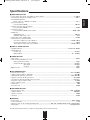
Specifications
• Power output, stereo mode, 6 Ω, THD 0.7%, 40 Hz~20 kHz ...................................................................................... 2× 100 W
• Total harmonic distortion, 6 Ω, 100 W, 1 kHz ................................................................................................................. 0.03 %
• Intermodulation distortion
60 Hz : 7 kHz= 4 : 1 SMPTE, 6 Ω, 100 W ................................................................................................................... 0.1 %
• Input sensitivity, 47 kΩ
Line (CD, TAPE, VIDEO) ........................................................................................................................................ 200 mV
• Signal to noise ratio, IHF “A” weighted
Line (CD, TAPE, VIDEO) .......................................................................................................................................... 95 dB
• Frequency response
Line (CD, TAPE, VIDEO), 10 Hz~75 kHz ...................................................................................................... +0 dB, -3 dB
• Output level
TAPE REC, 2.2 kΩ .................................................................................................................................................. 200 mV
PRE OUT (Subwoofer), 1 kΩ ........................................................................................................................................ 1.0 V
• Bass/Treble control, 100 Hz/10 kHz ............................................................................................................................... ±12 dB
• Surround mode, only channel driven
Front power output, 6 Ω, 1 kHz, THD 0.7 % ................................................................................................ 110 W / 110 W
Center power output, 6 Ω, 1 kHz, THD 0.7 % .......................................................................................................... 110 W
Surround power output, 6 Ω, 1 kHz, THD 0.7 % .......................................................................................... 110 W / 110 W
■ DIGITAL AUDIO SECTION
• Sampling frequency .................................................................................................................................. 32, 44.1, 48, 96 kHz
• Digital input level
Coaxial, 75 Ω .......................................................................................................................................................... 0.5 Vp-p
Optical, 660 nm .......................................................................................................................................... -15 ~ -21 dBm
■ VIDEO SECTION
• Video format .................................................................................................................................................................... NTSC
• Input sensitivity (=Output level) , 75 Ω
Video (Composite (normal)) ...................................................................................................................................... 1 Vp-p
Component video (R-Y signal) ............................................................................................................................... 0.5 Vp-p
(B-Y signal) ............................................................................................................................... 0.5 Vp-p
(Y signal) ...................................................................................................................................... 1 Vp-p
• HDMI connector ................................................................................................................................................................ 19 pin
■ FM TUNER SECTION
•
•
•
•
•
•
•
•
•
Tuning frequency range .................................................................................................................................. 87.5 ~ 108 MHz
Usable sensitivity, THD 3%, S/N 30 dB ...................................................................................................................... 12.8 dBf
50 dB quieting sensitivity, mono/stereo ........................................................................................................... 20.2 / 45.3 dBf
Signal to noise ratio, 65 dBf, mono/stereo ............................................................................................................... 55 / 50 dB
Total harmonic distortion, 65 dBf,1 kHz, mono/stereo .............................................................................................. 0.5 / 1.0 %
Frequency response, 30 Hz~12 kHz ............................................................................................................................ ±3.0 dB
Stereo separation, 1 kHz ................................................................................................................................................ 30 dB
Capture ratio ...................................................................................................................................................................... 4 dB
IF rejection ratio ............................................................................................................................................................... 80 dB
■ AM TUNER SECTION
•
•
•
•
Tuning frequency range ................................................................................................................................... 520 ~ 1710 kHz
Usable sensitivity ....................................................................................................................................................... 500 µV/m
Signal to noise ratio ......................................................................................................................................................... 40 dB
Selectivity .......................................................................................................................................................................... 25 dB
■ GENERAL
•
•
•
•
Power supply ...................................................................................................................................................... 120 V ~ 60 Hz
Power consumption ......................................................................................................................................................... 3.8 A
Dimensions (W× H× D, including protruding parts) .............................. 440× 141× 370 mm (17-3/8× 5-1/2× 14-1/2 inches)
Weight (Net) .................................................................................................................................................... 8.8 kg (19.4 lbs)
Note: Design and specifications are subject to change without notice for improvements.
43
ENGLISH
■ AMPLIFIER SECTION
cover_6504:cover_6504 2009-02-12 오
9:06 페이지 1
RD-6504
AUDIO/VIDEO RECEIVER
RECEPTOR DE AUDIO/VIDEO
RECEPTEUR AUDIO/VIDEO
5707-00000-199-0S