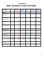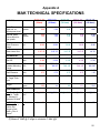
1
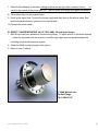
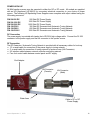
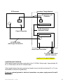
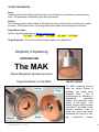
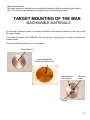
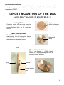
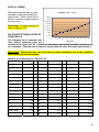
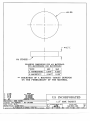
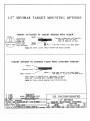
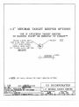
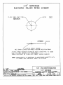
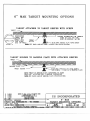
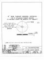
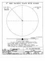
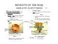
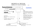
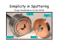
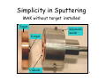
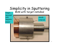
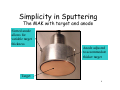
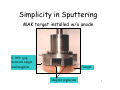
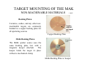
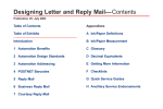
TM
OWNER’S OPERATION
AND
MAINTENANCE MANUAL
OF THE
MAK SPUTTERING SOURCES
5830 Hellyer Avenue
San Jose, CA 95138
PH: (408) 362.1000 FX: (408) 362.1010
E-MAIL: [email protected]
YOUR S/N _____________________________
WARNING
AS WITH ALL ELECTRICAL DEVICES, THERE IS A SHOCK HAZARD
ASSOCIATED WITH THIS DEVICE.
ALL INSTRUCTIONS SHOULD BE
FOLLOWED PERTAINING TO THE USE OF SUITABLE INTERLOCKS ON ALL
POWER SUPPLIES TO BE USED TO POWER THIS PRODUCT.
Issued September 11, 2008
Precautions to assure the proper operation of your MAK Source
• Water MUST be flowing thru the MAK while sputtering. Please see O&M manual for flow
requirements.
CAUTION
If MAK has been operated without water --- DO NOT turn the water on --- allow
the MAK to cool down before turning water on.
• Target paste [supplied with MAK] MUST be used. This provides a thermal layer between
the target and cathode [Copper block]. It is required to protect against uneven or irregular
surfaces of the target and / or cathode.
CAUTION
Failure to use target paste can damage the MAK. A VERY SMALL AMOUNT
MUST BE APPLIED -- A GLOVED FINGER USED TO SPREAD EVENLY OVER
THE CATHODE BLOCK. The block should be clearly visible --- thru a thin gray
film.
NOTE: A substitute paste such as thin [0.005”] Indium foil can also be used.
• A keeper MUST be used for all targets --- including magnetic. The keeper is used for
centering the target and maintaining a continuous magnetic path.
• Ceramic or Oxide targets --- MUST --- be bonded to a copper backing plate that contains a keeper.
• MAK Sputter Sources should be CLEANED on a routine basis. This is easily accomplished during target change.
1. With target removed, clean entire cathode assembly --- removing any foreign material
present. Cleaning of both inside and outside of the block is suggested.
2. Clean the anode shield.
Issued September 11, 2008
2
Table of Contents
Introducing US, a Division of MeiVac, Inc............................................................................................ 4
MeiVac, Inc. QUALITY ASSURANCE .................................................................................................... 4
Introducing MAK Sputter Sources........................................................................................................ 4
Magnetron Sputtering?.......................................................................................................................... 5
RF Sputtering.......................................................................................................................................... 7
Operation of the MAK ............................................................................................................................ 8
VACUUM SYSTEMS……………………………………………………………………………………………………………9
Installation of Sources......................................................................................................................... 10
Power Hook-up ..................................................................................................................................... 12
DC CONNECTION………………………………………………………………………………………………………….. 12
RF CONNECTION……………………………………………………………………………………………………………12
Target Parameters................................................................................................................................ 14
PURITY………………………………………………………………………………………………………………………14
SURFACE…………………………………………………………………………………………………………………….14
TARGET DIMENSIONS……………………………………………………………………………………………………….14
TARGET SUPPLIERS…………………………………………………………………………………………………………14
MACHINABLE MATERIALS……………………………………………………………………………………………………15
NON-MACHINABLE MATERIALS……………………………………………………………………………………………...16
Target Mounting……………………………………………………………………………………………….. 16
Rate vs. Power…………………………………………………………………………………………………..18
Relative Sputtering Rates of 50 Materials………………………………………………………………….18
Relative Rates of Sputtering Sources vs. Distance……………………………………………………… 19
Returns & Warranty.............................................................................................................................. 20
APPENDIX A: MAK TECHNICAL SPECIFICATIONS .......................................................................... 21
APPENDIX B: TARGET SUPPLIERS ................................................................................................... 23
TARGET DIMENSIONS 1.3"
2.0"
3.0"
4.0"
6.0"
SPARE PARTS
2.0"
3.0"
4.0"
6.0"
TUTORIALS
Issued September 11, 2008
1.3"
{Benefits}
{Simplicity}
{TargetMounting}
3
INTRODUCING US, a Division of MeiVac, Inc.
US has been an innovative manufacturer of sputtering since 1977. Exclusive licenses were obtained from Stanford University and Lawrence Livermore Laboratory to build and distribute their
patented magnetron sputtering sources on a worldwide basis.
MeiVac, Inc. QUALITY ASSURANCE
All MeiVac products are manufactured under the most stringent conditions. This includes proper
selection & inspection of original materials, assembly in clean environments, and complete testing
for leaks & functionality. These quality products are packaged in durable containers for shipment
throughout the world.
INTRODUCING MAK SPUTTER SOURCES
The MAK sputter sources were designed, developed & tested under controlled laboratory conditions at a major United States government laboratory. This low cost planar magnetron sputtering
source is compact, easy to install and requires no target bonding. All of the MAK sputter sources
(1.3, 2, 3, 4, and 6 inch) provide shielded electrical paths which allow RF as well as DC power to
the cathode with minimum line losses and low reflection of RF power.
The MAK sputter source has a unique feature of allowing low operational pressures (0.5 millitorr)
as well as high operational pressures (600 millitorr) without losing the focused plasma to the target.
The MAK sputter source is available in non-UHV and UHV designs.
Issued September 11, 2008
4
MAGNETRON SPUTTERING
Observations of the phenomenon we now call sputtering, go back over one hundred years to early
experiments which introduced electricity into a reduced pressure atmosphere. L. Holland describes these beginnings in his book Vacuum Deposition of Thin Films.
“When an electrical discharge is passed between electrodes at a low gas pressure, the cathode
electrode is slowly disintegrated under the bombardment of the ionized gas molecules. This phenomenon is termed cathodic sputtering. The disintegrated material leaves the electrode surface
either as free atoms or in chemical combination with the residual gas molecules. Some of the liberated atoms are condensed on surfaces surrounding the cathode while the remainder are returned to the cathode by collision with gas molecules.”
The ensuing process might be compared to a fine sand blasting in which the momentum of the
bombarding particles is more important than their charge. The inert gas argon was chosen, to act
as the sputtering medium, because it is a heavy rare gas and is plentiful. It also has a low ionization potential. The inert nature of argon inhibits compounds from being formed at the target surface.
Once sputtered, the target atoms travel until they reach a nearby surface most notably, the substrate. The deposited layer forms or grows on the substrate structure, influenced by such things as
material, temperature and gas structure.
When the ions strike the target, their primary electrical charge is neutralized (gain back the lost
electron) and they return to the process as atoms. Thus, direct current sources generally prevail
as the electrical energy source.
Issued September 11, 2008
5
In order to increase sputtering rate, magnetic coils were sometimes placed around the chamber to
pinch the plasma during the deposition. The pressure was reduced to 20 microns (2 X 10⁻² torr)
and the rates increased. The electrodes were close together and the R.F. voltage was high.
These conditions caused damage to semiconductor devices due to the high electron and secondary ion bombardment, which took place.
When it was realized how important the role of a magnetic field was in concentrating the plasma
and the effects that it had on rate, sputtering became more attractive as a commercial process.
Several magnetic configurations were used such as the post cathode, magnetically enhanced hollow cathodes and magnetrons. In order to make a magnetron work, it is necessary to cause the E
X B drift currents to close on themselves. This realization led to the magnetron cathode designs
that are in use today.
MAK BENEFITS
BENEFITS OF THE MAK
SIMPLICITY IN SPUTTERING
Magnetics
•
•
•
•
Balanced / Unbalanced
Magnet array is
INTERCHANGEABLE from balanced or unbalanced. Disassembly of source NOT
REQUIRED!
Cathode
Ring Magnet
No Magnetic Housing
Provides higher magnetic density at target surface
Sputters at lower voltage for
comparable power levels
Standard MAK sputters magnetic material
Issued September 11, 2008
Center Magnet
Adjustable Anode Set
Screws
6
RF SPUTTERING
If the target is an insulator, the neutralization process results in a positive charge on the target surface. This charge may grow to the point that the bombarding ions (±) are repelled and the sputtering process will stop. In order to make the process continue the polarity of the target must be reversed to attract enough electrons from the discharge to eliminate the surface charge. In order to
attract the electrons and not repeal the ions, the frequency must be high enough to reverse before
the direction of the ions are affected. The usual industrial frequency assigned by the FCC for such
is in the MHz range. Since this is a “radio” frequency, the process is called radio frequency sputtering, or RF sputtering. Most of the early sputtering was done using direct current sources. This
meant high voltage, with current draw being limited by the gas pressure. Typical voltages were 3-5
kV with a current from 50-250 ma at pressures of 50-250 microns. R.F. power was introduced because it makes it possible to sputter insulators.
BENEFITS OF THE MAK
SIMPLICITY IN SPUTTERING
Physical Parameters
VACUUM SEAL
•
•
•
One Vacuum Seal
Elastomer (HV) or Metal (UHV) field
interchangeable
No water to Vacuum Seal
•
•
•
Small Profile
Mounts on CF, ISO or installs thru a
Quick Disconnect
As example, standard 3” MAK fits thru
opening of 6” CF
Anode
Height adjustable to target
thickness - Selectively positioning anode to same plane as target --- obviously minimizing material build-up
No Mechanical Target Clamp
Target surface is not in contact
with dissimilar clamping material
--- minimizing stress during sputtering and cool down
PICTURE SHOWN IS NOT
TO SCALE
HN CONNECTOR
WATER LINES
•
Teflon water lines with quick disconnects
Issued September 11, 2008
•
Standard HN power connector
permits RF/DC operation
7
OPERATION OF THE MAK
VACUUM SYSTEMS
To successfully operate the MAK Series, a leak-tight vacuum system must be available. This system should be pumped with a high vacuum pump of the turbo, or a cryo type. It may be necessary
to have a throttle valve, or orifice in the system to control pump throughput while the sputtering gas
is introduced. If a cryopump is used, the throttle valve may not be required, however, it is desirable
if sputtering gas pressures of more than five microns are to be used.
The vacuum system should be equipped with suitable gauging to measure and monitor pressures
in the 0.5-600 micron range during sputtering, and the 1x10⁻⁵ to 1x10⁻⁹ torr range during pre-sputter
pump down. The system must also be equipped with a fine metering valve and separate in-series
shut-off valve used for the introduction of the sputtering gas.
A suitable fixture for mounting and holding the substrate(s) during film deposition should be provided, in conjunction with a means of shuttering the source (target) from the substrate during precleaning of the target.
Since the MAK Series will not operate properly if the shutter is positioned too close to the
target, it is suggested that the total distance from target to shutter be at least 1”.
Issued September 11, 2008
8
To obtain ideal uniformity, the distance from source to substrate should be adjustable.
Note: The rate will decrease by the square of the distance from source to substrate, however uniformity will be enhanced as this distance is increased.
The chamber may be made of glass or metal. If the chamber is metal, a viewing port should be
provided for observation during sputtering.
Issued September 11, 2008
9
INSTALLATION OF SOURCES
STANDARD MOUNTING
To mount the source a QUICK COUPLE feedthrough adapter is required. A 0.75” adapter is used
for the 1.3”, 2”, and 3”, and 4” sources. The 6” MAK requires a 1.25” quick coupler adapter.
Water Lines
Power Connector
(HN)
End Adapter
Atmosphere
Vacuum
Vessel
HN Power Pin
Tube Clamp
Quick Coupler
MAK Installed in Vacuum
Chamber
A. PREPARING THE SOURCE FOR MOUNTING VIA A QUICK COUPLER
1. Loosen the screws on the End Adapter holding the electrical connector on the end of the tube.
2. Pull straight out on the electrical connector mounting assembly. The whole assembly will come
off, leaving the water tubes free and the electrical connector assembly unplugged from the
power feed rod.
3. Remove the tube clamp from the tube. This clamp is designed to keep the source in position
when the system is under vacuum.
4. From the inside of the vacuum system, insert the water tubes into the feedthrough hole, and
then insert the tube. Position the tube to the approximate desired source to substrate distance.
5. Slide on the “O” ring, compression ring and coupler nut. Hand tighten the nut.
6. Slide on the clamp tube, position and tighten.
Issued September 11, 2008
10
7. Slide the End Adapter on the tube, making sure that the slip pin in the connector body is
in-
serted in the socket of the power feed rod. Push on as far as it will go and tighten the screws.
8. The system may now be pumped down.
9. Hook up the water lines. Connect the house supply and drain lines to the source tubes. See
technical specifications for minimum flow requirements.
10. Connect the power cable.
B. DIRECT FLANGE MOUNTING VIA CF, ISO, ANSI, JIS and other flanges
1. MAK Source has been attached to the mounting flange. To adjust source to substrate distance
--- either the substrate must be moved or a feedthrough nipple must be placed between the
mounting flange and the vacuum system.
2. Attach the MAK mounting flange to the system.
3. Refer to step (7) above.
3” MAK Welded onto
Conflat Flange
PN: L300A01-CF
Issued September 11, 2008
11
POWER HOOK-UP
All MAK sputter sources may be operated in either the DC or RF mode. All models are supplied
with an HN (Amphenol UG-496/U) for convenient electrical connection to your choice of power
source. The following US Sputtering Power Supplies come complete with output cables having the
HN mating connector.
P/N SU-500 DC
P/N SU-1500 DC
P/N SU-5000 DC
P/N: SU-R301
P/N: SU-R601
P/N: SU-R1001
500 Watt DC Power Supply
1500 Watt DC Power Supply
5000 Watt DC Power Supply
300 Watt RF Generator and Automatic Tuning Network
600 Watt RF Generator and Automatic Tuning Network
1000 Watt RF Generator and Automatic Tuning Network
DC Connection
The power supply is provided with twelve feet of RG 8/U high voltage cable. Connect the PL 259
connector to the power supply and the HN connector to the sputter source.
RF Connection
The RF Generator / Automatic Tuning Network is provided with all necessary cables for hook-up.
12’ co-axial cable for connection of the power supply to tuning network
3’ co-axial cable for connection of tuning network to sputter source (HN Connector)
24’ interface cable between network controller and tuning network
Four-foot control cable between control panel and RF supply
End Adapter
HN Connector
(Female)
HN Connector
(Male)
Water lines
Cable to RF or DC
Power Supply
Issued September 11, 2008
12
RF Generator
Auto Tuning Network
D Connector to D
Connector
Power Connection
50 Pin Connectors
with metal covers
12’ RG-8U Cable
with N Type Connections
Input Power Connection
3’ or 5’ RG 393/U Cable
with HN Connector
OUTPUT TO SPUTTERING
CAUTIONS IN RF HOOK-UP
Cable length between should be a derivative of the 13.56 MHz. Wave length. Approximately 48,
24, or 12 feet and be 50 ohm RF shielded cable.
Cable length between the tuning network and sputter source should be minimized (3’ or 5’ is recommended for use with US generators).
Do not use external grounds at electrical connections; see power supply manual for additional details.
Issued September 11, 2008
13
TARGET PARAMETERS
Purity
Target material for the MAK sputtering source is not confined to a minimum or maximum purity
level. This parameter is dependent upon film requirements.
Surface
The mounting (bottom side) surface of the target should be smooth and flat to allow good contact
to source. The top and bottom of the target should be parallel for best deposition uniformity.
Target Dimensions
See the Target Specifications at www.us-incorp.com.
[1.3” MAK] [2.0” MAK] [3.0” MAK]
[4.0” MAK]
[6.0” MAK]
Target Suppliers – For a list of qualified target suppliers, see Appendix B.
Simplicity in Sputtering
INTRODUCING
The MAK
Planar Magnetron Sputtering Source
Target Installation on the MAK
TARGET KEEPER
Cathode
Target
Magnets
Issued September 11, 2008
Keeper
The MAK sputtering sources
have the unique feature of
attaching the target using
magnetic force.
This is
accomplished by attaching a
magnetically
permeable
“keeper” (see appendix) to the
bottom of the target.
This
keeper coupling with the magnetic field of the MAK source
provides sufficient force to
clamp and center the target,
eliminating the need for complex
mechanical
clamps.
14
Machinable Materials
The target keeper can be attached to machinable materials by drilling and tapping the target to
90% of it’s thickness and attaching the keeper using a vented flat head screw.
TARGET MOUNTING OF THE MAK
MACHINABLE MATERIALS
By attaching a magnetic keeper to the target, the MAK source uses the magnetics of the gun to hold
the target in place.
If you have old targets, NO PROBLEM! Drill and tap your existing targets as shown and attach the
metallic keeper.
Then, snap the target into place. It’s that simple!
Target Material
Target Material with
Drilled and Tapped Hole
Target Material
with Keeper
Mounting
Screw
Keeper
15
Non-Machinable Materials
Ceramic and oxide materials, a copper backing plate containing a magnetic keeper should be
used. The target must be bonded to this backing plate and this bond must be able to withstand a
temperature of 220oC.
TARGET MOUNTING OF THE MAK
NON-MACHINABLE MATERIALS
Backing Plates
Ceramics, oxides, and any other non- machinable targets are commonly bonded to a
copper backing plate for all sputtering
sources.
Cu plate with
drilled and tapped
hole
MAK Backing Plates
The MAK sputter source uses the same
backing plate, but with a magnetic keeper
attached. The keeper holds the target in
place without a mechanical clamp.
Keeper with
screw
bond
Bonded Target - Example
This is an example of a SiO2 target
bonded to a copper backing plate with a
magnetic keeper attached.
target
keeper
copper backing
plate
16
Copper Backing Plate Specifications (See Appendix A)
MAK 1.3” Copper Backing Plate
Part Number: MAK-130-BP
MAK 2” Copper Backing Plate
Part Number: MAK-200-BP
MAK 3” Copper Backing Plate
Part Number: MAK-300-BP
MAK 4” Copper Backing Plate
Part Number: MAK-400-BP
MAK 6” Copper Backing Plate
Part Number: MAK-600-BP
Caution
Failure to use thermal contact paste or a thin metal foil as an interface layer between the
target and the copper cooling block can cause over heating and may damage the MAK
source and/or target.
Simplicity in Sputtering
MAK with target installed
Target
mounted with
magnetic
keeper
Anode retracted
Remove the Anode
1. Spread a small amount of thermal contact paste on the top of the copper chill
block. The paste should be spread evenly and so thin you can see through it.
a) If the thermal contact paste is not used a thermally and electrically conductive foil e.g.
indium ~0.005” thick with a donut shape slightly smaller than the cathode/chill block
must be placed between the block and the target.
b) Place the target at the center of the source assuring that the magnetic keeper has
been properly positioned in the recessed center magnet cavity. Twist slightly to
evenly distribute the thermal contact paste.
c) Replace Anode
NOTE: A target keeper is not required with magnetic materials; however, the user should take
care to insure even spacing between the O.D. of the target and the I.D. of the ground shield.
Thermal Contact Paste
Part Number TP-832
17
RATE VS. POWER
When gathering rate data, it is also
desirable to take rates at different
power levels. These values can be
plotted to produce a graph similar to
the one shown.
Please Note: For approximating DC
rates, multiply by 1.75.
CO PPER 2" Dia., 3" Dist.
40.00
35.00
Å 30.00
/ 25.00
s 20.00
e 15.00
c 10.00
5.00
RELATIVE SPUTTERING RATES OF
0.00
50 MATERIALS
0
50 100 150 200 250 300 350 400 450 500
The following list of materials and
W atts RF
their relative sputtering rates are
normalized to copper as 1.00. Copper is a convenient and readily available material to use
as a reference. Once the rate of copper is known, then the other 49 may be approximated.
Please Note: These rates may vary from those of other periodicals, due to the conditions
under which the rates were taken.
Element (or compound) Cu = Rate of 1.00
Ag
2.06
Gd
1.17
Rh
0.74
Al
0.73
Ge
1.05
Ru
0.66
Al2O3
0.15
Glass
0.23
Sb
3.68
Au
1.76
Hf
0.67
Si
0.39
Be
0.22
Ir
0.61
SiC
0.36
Bi
10.00
Mg
0.26
SiO
0.27
C
0.05
MgF
0.03
SiO2
0.45
CdS (1010)
2.39
Mn
0.99
Sm
1.14
CdTe
0.64
Mo
0.53
Sn
1.38
Co
0.58
Nb
0.44
Ta
0.43
Cr
0.60
Ni
0.65
Th
0.84
Cu
1.00
Os
0.5
Ti
0.38
Dy
1.18
Pb
3.52
U
0.73
Er
1.00
Pd
1.31
V
0.38
Fe
0.56
Pt
0.9
W
0.39
GaSa (110)
1.70
Rb
4.55
Y
0.95
Re
0.53
Zr
0.65
18
RELATIVE RATES OF SPUTTERING SOURCES VS DISTANCE
Rate data, for sputtering with small sources, is usually taken by making step samples and
then measuring them with either profilometer or interferometer. A quartz crystal microbalance type rate monitor may also be used. If a rate monitor is used, the geometry and the
density of the deposit must be taken into account. Because of the uncertainties of rate
monitor data, the most prudent course is to correlate the values taken with the rate monitor
with those taken by step sample method.
If the distance from the substrate to the target is changed and the power remains constant, the
change in deposition rate is a function of the ratio of the distances squared. For example, if the
rate at a 3” target to substrate distance is 15 Å/sec., the power is constant and the distance
changes from 3” to 4”, the rate drops to 8.4 Å/sec.
Rate at 3” = 15 Å/sec.,
Ratio for a change from 3” to 4” = 32/42 = 9/16 = 0.563
Ratio times Rate at 3” = 0.563 x 15 Å/sec = 8.4 Å/sec
Many factors affect deposition rate, but this is a reasonable approximation of the effect of distance.
19
Claims & Returns
Shipping and Handling Claims
Purchaser should inspect the product carefully as soon as it is received and test it in accordance with any
instructions that may be provided. If damage is noted, or the product fails to operate properly as the result
of shipping or handling damage, a claim should be filed with the common carrier and a copy forwarded to
MeiVac or its distributor. MeiVac or its distributor will not recognize any claim for equipment damaged as a
result of shipping or handling damage if the claim is submitted more than thirty days after MeiVac’s or its
distributor’s shipment of the product. Failing to report any damage within this period shall be considered an
acknowledgement by Purchaser that the product was received undamaged.
Warranty Claims
For a warranty claim to be valid, it must:
• be made within the applicable warranty period,
• include the product serial number and a full description of the circumstances giving rise to the claim, and
• have been assigned an RMA number (see Authorized Returns) by MeiVac or its distributors.
Purchaser’s exclusive remedy and MeiVac’s sole responsibility under the Warranty set forth herein is the
repair or replacement of the defective product, at MeiVac’s option. Purchaser shall reimburse MeiVac for
the repair of any returned product determined by MeiVac not to be defective or to have been damaged by
misuse, abuse or unauthorized repair. All warranty work will be performed at an authorized MeiVac service
center.
Purchaser is responsible for obtaining authorization (see Authorized Returns) to return any defective units,
prepaying the freight costs, and ensuring that the units are returned to the location identified by MeiVac on
the RMA. Provided the work required on the unit is covered under the Warranty, MeiVac will replace the affected unit or repair it at no charge to Purchaser. On completion of said repair or replacement, the unit will
be returned (freight prepaid) to the Purchaser. Whoever ships the unit (either Purchaser or MeiVac) will be
responsible for properly packaging and adequately insuring it.
Authorized Returns
Before returning any product for any reason, Purchaser shall call MeiVac or its distributor and discuss the
reason for return. Be prepared to give the serial number of the unit. This consultation call shall be at no
charge to the Purchaser and will allow MeiVac or its distributor to determine if the unit must actually be returned for a problem to be corrected. If it is determined that the unit needs to be returned a Return Material
Authorization (RMA) number will be issued. This RMA number must be referenced on all paperwork associated with the return, and be prominently displayed on the outside of any packaging that the unit is being
returned in.
Units that are returned without MeiVac’s or its distributor’s authorization will be held by MeiVac or its distributor until such time as Purchaser can identify the reason for the return, after which, action deemed appropriate by MeiVac or its distributor (including return of the unit to Purchaser freight collect) shall be taken.
Terms governing all products sold by US, a Division of MeiVac are the MeiVac Terms and Conditions of
Sale. These can be found on the MeiVac web site (www.meivac.com), the US web site (www.usincorp.com) or obtained from your local representative.
20
Appendix A
MAK TECHNICAL SPECIFICATIONS
MAK SIZE:
MAK 1.3"
MAK 2"
MAK 3"
MAK 4"
MAK 6"
(33mm)
(50.8mm)
(76.2mm)
(101.6mm)
(152.4mm)
TARGET
mm
inch
1.00-5.70
0.040-0.225
1.00-9.50
0.040-0.375
1.00-15.90
0.040-0.625
1.00-19.05
0.040-0.750
2.00-25.40
0.080-1.000
mm
inch
1.00-2.54
0.040-0.100
1.00-4.70
0.040-0.187
1.00-6.35
0.404-0.250
1.00-9.50
0.404-0.375
2.00-11.00
0.080-0.437
ccm
cu inch
4.90
0.30
19.25
1.17
72.47
4.42
154.00
9.40
463.00
28.25
cm. sq.
sq in
8.56
1.33
20.27
3.14
45.60
7.07
81.10
12.56
182.4
28.25
watts
350.00
1000.00
2000.00
3000.00
6000.00
watts
200.00
400.00
750.00
1200.00
2000.00
Max Power DC (Per)
cm sq
in sq
40.88
263.00
49.30
318.00
43.86
283.00
37.00
240.00
33.00
212.00
Max Power RF (Per)
cm sq
in sq
24.00
150.00
20.00
130.00
17.00
106.00
15.00
96.00
11.00
70.00
amps
1.00
3.00
5.00
7.00
10.00
200-1000
200-1000
200-1000
200-1000
200-1000
Target Thickness
min-max
Magnet Target- (1)
Thickness min-max
Target Volume
max
Target Surface Area
ELECTRICAL
Max Power Dc
Max Power RF
Max Current
VOLTAGE Min-Max
21
Appendix A
MAK TECHNICAL SPECIFICATIONS
COOLING
Water Flow at
30psi min. at
lowest power level
Nominal Water
Flow at 60psi for
max. power
Water Pressure
Range
MAK 1.3"
MAK 2"
MAK 3"
MAK 4"
MAK 6"
(33mm)
(50.8mm)
(76.2mm)
(101.6mm)
(152.4mm)
l/min
gal/min
3.48
0.90
3.48
0.90
3.48
0.90
3.48
0.90
7.00
1.840
l/min
gal/min
6.20
1.60
6.20
1.60
6.20
1.60
6.20
1.60
12.40
3.20
2.1-5.6
30-80
2.1-5.6
30-80
2.1-5.6
30-80
2.1-5.6
30-80
2.1-5.6
30-80
1/4" OD
3/16" ID
1/4" OD
3/16" ID
1/4" OD
3/16" ID
1/4" OD
3/16" ID
3/8" OD
1/4" ID
mm
inch
59.70
2.350
59.70
2.350
85.80
3.378
104.80
4.125
170.80
6.725
CF
ISO
4-1/2"[DN63]
NW 63
4-1/2"[DN 63]
NW 63
6"[DN 100]
NW 100
6-3/4”[DN125]
NW 160
10"[DN200]
NW 200
mm
inch
19.05
0.75
19.05
0.75
19.05
0.75
19.05
0.75
31.75
1.25
NO
YES
YES
YES
YES
1.75
3.85
2.0
4.4
4.0
8.8
5.5
12.1
13.0
28.6
35@200W
100@500W
[email protected]
[email protected]
145@5KW
5%
6%
8%
8%
7%
Bar
psi
Water Lines Size
MECHANICAL
Max OD
Smallest Mounting
Flange
Shaft Diameter
Anode Adjustable
To Target Thickness
Weight
lbs.
kgms.
PERFORMANCE
Rate For Cu @ 5
mtorr Ar. Target
To Substrate =
Diameter Of MAK2
Angstrom /
Sec
UNIFORMITY
Substrate Dia. =
Source Dia.
Target to Substrate = Dia. of
Source2
+%
(1) Maximum magnetic target thickness is material dependent.
(2) Means 2” MAK @ 2” target to substrate 4” MAK @ 4”
22
APPENDIX B
TARGET SUPPLIERS
ACI Alloys, Inc.
1985 Las Plumas Avenue
San Jose, CA 95133
Larry Albert
PH: (408) 259-7337
FX: (408) 729-0277
www.acialloys.com
SCI Engineered Materials
2839 Charter St.
Columbus, OH 43228
PH: (800) 346-6567
FX: (800) 292-8654
www.sciengineeredmaterials.com
Cerac, Inc.
Box 1178
Milwaukee, WI 53201
Rick Vehlow
PH: (414) 289-9800
FX: (414) 289-9805
www.cerac.com
Sputtering Target Manufacturing Co.
1005 Corbin Court
Westerville, OH 43081
J.R. Gaines
PH: (614) 446-2202
FX: (740) 965-5701
www.sputtertarget.com
Praxair
16130 Wood Red Road #7
Woodinville, WA 98072
Ron Ekdahl
PH: (425) 487-1769
FX: (425) 487-1859
www.praxair.com
Tico Titanium
52900 Grand river
New Hudson, MI 48165
Mr. J.P. Cruzen
PH: (800) 521-4392
FX: (248) 446-1995
www.ticotitanium.com
Process Materials, Inc.
5625 Brisa Street, Suite A
Livermore, CA 94550
Steve Verley
PH: (925) 245.9626
FX: (925) 245.9629
www.processmaterials.com
Vacuum Engineering & Materials Co.
131-B Albright Way
Los Gatos, CA 95032
Gina Craig
Jack Kavanaugh
PH: (408) 871-9900
TOLL FREE: (877) 986-8900
FX: (408) 871-2900
www.vacengmat.com
SCI Engineered Materials
2839 Charter St.
Columbus, OH 43228
PH: (800) 346-6567
FX: (800) 292-8654
www.sciengineeredmaterials.com
Williams Advanced Materials
42 Mt. Ebo Road South
Brewster, NY 10509
PH: (845) 279-0900
FX: (845) 279-0922
www.williams-adv.com
Sputtering Target Manufacturing Co.
1005 Corbin Court
Westerville, OH 43081
J.R. Gaines
PH: (614) 446-2202
FX: (740) 965-5701
www.sputtertarget.com
23
1.3”
MAK
US Part Number
Description
L130-04
Ceramic Ground Shield
L130-06
Ring Magnet
L130-09
Stainless Steel Ground Shield
L130A14
Block Assembly
J1200-06
Center Magnet
J1200-33
O-Ring
J1200-34M
Metal Seals
J1234-30
Water Lines (2)
LL-130-01
Keeper w/ hole & screw (pkg. 10)
MAK-130-BP
Copper Backing Plate w/ Keeper
TP-832
Thermal Contact Paste - 0.5 oz.
w/ ferrules
42
2.0”
MAK
US Part Number
Description
L200-07
Ring Magnet
L200-10
Aluminum Ground Shield
L200A14
Block Assembly
J1200-06
Center Magnet
J1200-33
O-Ring
J1200-34M
Metal Seals
J1234-30
Water Lines (2)
LL-200-01
Keeper w/ hole & screw
10)
MAK-200-BP
Copper Backing Plate w/ Keeper
TP-832
Thermal Contact Paste - 0.5 oz.
w/ ferrules
(pkg.
42
3.0”
MAK
US Part Number
Description
L300-10
Aluminum Ground Shield (OLD STYLE
MAK SOURCE ONLY)
L300-10NT
Aluminum Ground Shield
L300-13
Center Magnet
L300-24
Ring Magnet
L300A14
Block Assembly
J3400-33
O-Ring
J3400-34M
Metal Seals
J1234-30
Water Lines (2) w/ ferrules
LL-300-01
Keeper w/ hole & screw (pkg. 10)
MAK-300-BP
Copper Backing Plate w/ Keeper
TP-832
Thermal Contact Paste - 0.5 oz.
42
4.0”
MAK
US Part Number
Description
L400-10
Aluminum Ground Shield
L400A20
Center Magnet Assembly
L400A14
Block Assembly
J4600-13
Center Magnet
J4600-32
Ring Magnet Segment
each)
J3400-33
O-Ring
J3400-34M
Metal Seals
J1234-30
Water Lines (2)
LL-400-01
Keeper w/ hole & screw (pkg. 2)
MAK-400-BP
Copper Backing Plate w/ Keeper
TP-832
Thermal Contact Paste - 0.5 oz.
(10 @ 31.25
w/ ferrules
42
6.0”
MAK
US Part Number
Description
L600-10
Aluminum Ground Shield
L600-40
O-ring Magnet Plug
L600-41
O-Ring
L600A14
Block Assembly
L600A20
Center Magnet Assembly
J4600-13
Center Magnet
J4600-32
Ring Magnet Segments
each)
L600-42
Water Lines (2) w/ ferrules
LL-600-01
Keeper w/ hole & screw (pkg. 2)
MAK-600-BP
Copper Backing Plate w/ Keeper
TP-832
Thermal Contact Paste - 0.5 oz.
(16 @ 31.25
42
BENEFITS OF THE MAK
SIMPLICITY IN SPUTTERING
Water Isolated from:
•
MAGNETS - NO magnet erosion
•
POWER - (ALL electrical components)
– no power changes due to water
resistance
– simplifies RF Tuning
NO special treatment of water needed
•
Cooling
Channel
1 OF 3
Cathode (Copper)
Only small volume above AlN has electrical
potential applied,
THUS…..
• minimizing heated area - facilitating
cooling
• all components except small cathode
area, are at ground or neutral potential
•
Cathode
Cooling Block
AlN
Magnet
Return
Passage for
Insulated Power
Post
•
•
Cooling Block (Copper)
Water channel 75% of volume,
THUS…..
High water flow - maximizing cooling
efficiency of copper surface area
Water Line
Water Line
Power
Feedthru
CATHODE BLOCK - without magnets
AlN - Alumina Nitride
Excellent:
•
•
Thermal Conductor
Electrical Insulator
BENEFITS OF THE MAK
SIMPLICITY IN SPUTTERING
2 OF 3
Magnetics
Cathode
•
•
Ring Magnet
Balanced / Unbalanced
Magnet array is
INTERCHANGEABLE from
balanced or unbalanced.
Disassembly of source NOT
REQUIRED!
No Magnetic Housing
Provides higher magnetic density at
target surface
THUS…..
– Sputters at lower voltage for
comparable power levels
– Standard MAK sputters
magnetic material
Adjustable Anode
Set Screws
Center Magnet
BENEFITS OF THE MAK
SIMPLICITY IN SPUTTERING
Physical Parameters
PICTURE SHOWN
IS NOT TO SCALE
VACUUM SEAL
•
•
•
•
3 OF 3
One Vacuum Seal
Elastomer (HV) or Metal (UHV) field
interchangeable
No water to Vacuum Seal
•
Small Profile
Mounts on CF, ISO or installs thru a Quick
Disconnect
As example, standard 3” MAK fits thru
opening of 6” CF (DN100)
•
Anode
Height adjustable to target thickness Selectively positioning anode to same
plane of target--- minimizing material
build-up
No Mechanical Target Clamp
Target surface is not in contact with
dissimilar clamping material--minimizing stress during sputtering
and cool down (especially for
ceramics and oxides)
HN CONNECTOR
•
WATER LINES
Teflon water lines with quick disconnects
•
Standard HN power connector permits
RF/DC operation
Simplicity in Sputtering
INTRODUCING
The MAK
Planar Magnetron
Sputtering Source
1
Simplicity in Sputtering
Target Installation on the MAK
Cathode
Magnets
Target
Keeper
2
Simplicity in Sputtering
• Targets mounted by attraction of the center magnet
• No mechanical clamping of the target
THUS…..
• Ease of target change
• Adjustable anode
THUS…..
• Allows for target thickness variations
• Prevents material build up
• Standard and/or existing targets used
3
Simplicity in Sputtering
MAK without target installed
Target
Keeper
Cathode
Adjustable
Anode
4
Simplicity in Sputtering
Target
mounted
with
magnetic
keeper
MAK with target installed
Anode
retracted
5
Simplicity in Sputtering
The MAK with target and anode
Slotted anode
allows for
variable target
thickness
Anode adjusted
to accommodate
thicker target
Target
6
Simplicity in Sputtering
MAK target installed w/o anode
0.100+ gap
between target
and magnets
Target
Magnet segments
7
TARGET MOUNTING OF THE MAK
NON-MACHINABLE MATERIALS
1 OF 2
Backing Plates
Ceramics, oxides, and any other nonmachinable targets are commonly
bonded to a copper backing plate for
all sputtering sources.
Cu plate
with drill
and tapped
hole
Copper Backing Plate
MAK Backing Plates
The MAK sputter source uses the
same backing plate, but with a
magnetic keeper attached.
The
keeper holds the target in place
without a mechanical clamp.
Keeper with
screw
MAK Backing Plate w/ keeper
TARGET MOUNTING OF THE MAK
NON-MACHINABLE MATERIALS
2 OF 2
bond
Bonded Target - Example
This is an example of a SiO2
target bonded to a copper
backing plate with a
magnetic keeper attached.
target
keeper
copper
backing plate
TARGET MOUNTING OF THE MAK
MACHINABLE MATERIALS
1 OF 1
By attaching a magnetic keeper to the target, the MAK source uses the
magnetics of the gun to hold the target in place.
If you have old targets, NO PROBLEM! Drill and tap your existing targets as
shown and attach the metallic keeper.
Then, snap the target into place. It’s that simple!
Target
Material
Target Material
With Drilled and
Tapped Hole
Target
Material
with Keeper
Keeper
Mounting
Screw