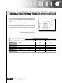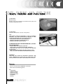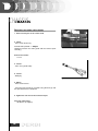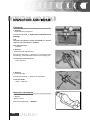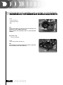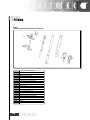
1
This manual has been produced by Nacional Motor, S.A.U. for use by DERBI dealer and sub-agency workshops. It is assumed that those using this publication for training purposes and for repairing DERBI machines
have a basic knowledge of mechanics and of the methods inherent in the technique of vehicle repair. Significant variations in the characteristics of the machines or in the specific repair operations will be communicated
by means of updates to this manual.
Completely satisfactory work cannot however be carried out without the availability of suitable facilities
and tools, which is why we ask you to consult the pages of this manual referring to special tools and implements.
Particularly important items of information in this manual are distinguished by the following annotations:
N.B.
INDICATES A NOTE GIVING KEY INFORMATION, MAKING THE PROCEDURE EASIER AND CLEARER.
ATTENTION
INDICATES SPECIFIC PROCEDURES THAT MUST BE FOLLOWED TO PREVENT DAMAGE TO THE MACHINE.
WARNING
INDICATES SPECIFIC PROCEDURES THAT MUST BE FOLLOWED TO AVOID POSSIBLE INJURIES TO THE
PERSON REPAIRING THE MACHINE.
NACIONAL MOTOR, S.A.U.
The Derbi logo is a registered trademark and property of DERBI - Nacional Motor, S.A. Sociedad Unipersonal.
The total or partial reproduction of any photograph, graphic or text inserted in this manual is prohibited.
© 2006 DERBI - Nacional Motor, S.A. Sociedad Unipersonal.
Design and layout by Cian disseny, S.L. - Sta. Eugènia de Berga (Barcelona) - www.ciandisseny.com
1
GENERAL INFORMATION
MAINTENANCE REGULATIONS
GENERAL TECHNICAL DATA
MAINTENANCE SPECIFICATIONS
TIGHTENING TORQUES
CHASSIS SPECIFICATIONS
ELECTRICAL SYSTEM SPECIFICATIONS
GENERAL TIGHTENING TORQUE SPECIFICATIONS
PERIODICAL INSPECTIONS AND ADJUSTMENTS
SEAT, FAIRING AND FUEL TANK
ENGINE
CHASSIS
ELECTRICAL SYSTEM
ENGINE INSPECTION
DISMANTLING THE ENGINE
INSPECTION AND REPAIR
REASSEMBLING THE ENGINE AND MAKING ADJUSTMENTS
CHASSIS – FRONT WHEEL AND BRAKES
REAR WHEEL AND BRAKES
TRANSMISSION
FORKS
HANDLEBARS
SHOCK ABSORBER AND SWINGING ARM
ELECTRICAL SYSTEM
INSPECTING THE SWITCHES
TROUBLESHOOTING
3
Page
Page
Page
Page
Page
Page
Page
Page
Page
Page
Page
Page
Page
Page
Page
Page
Page
4
5
6
11
15
17
19
21
24
26
28
35
40
44
45
56
65
Page
Page
Page
Page
Page
Page
Page
Page
Page
96
106
116
119
125
129
131
135
136
REGULATIONS
This section describes the machine’s general safety and maintenance work rules.
SAFETY
REGULATIONS
In the event of having to carry out work on the engine while this is running, ensure that the area is well ventilated, where possible using extractor fans. Never leave engines running in closed spaces. Exhaust gases
are poisonous.
Petrol is extremely inflammable and in certain conditions may explode. Smoking must not be allowed in the
work area, nor should there be naked flames or sparks.
MAINTENANCE
REGULATIONS
- Use genuine DERBI spare parts and lubricants recommended by the Manufacturer. Non-genuine or unauthorised parts may damage the engine.
- Always use new gaskets and oil seals during re-assembly.
- After dismantling, clean the components with solvents that are non-inflammable or with a high flammability
point. Lubricate all working surfaces before re-assembling, excluding tapered joints.
- After re-assembly, check that all components have been correctly fitted and that they are functioning perfectly.
- For dismantling, checking and re-assembly operations, use only tools with metric measurements. Metric
screws, nuts and bolts are not interchangeable with imperial measurement joining devices. Using unsuitable
tools and joining devices may damage the engine.
- In the case of work on the engine involving the electrical circuitry, check that electrical connections have
been correctly fitted.
4
Use genuine DERBI spare parts and lubricants recommended by the Manufacturer. Non-genuine or unauthorised parts may damage the machine.
Only use the specific tools intended for this machine.
During re-assembly, always use new seals, gaskets, piston
rings and grommets.
After dismantling, clean the components with solvents that
are non-inflammable or that have a high flammability point.
Grease all working surfaces before assembling, excluding
tapered joints.
After assembly, check that all components have been correctly fitted and that they are functioning perfectly.
For dismantling, checking and re-assembly operations, use
only tools with metric measurements. Metric screws, nuts
and bolts are not interchangeable with imperial measurement joining devices. Using unsuitable tools and joining devices may damage the machine.
In the case of work on the machine’s electrical circuitry,
check that electrical connections have been correctly fitted,
especially the earth connections.
VEHICLE
IDENTIFICATION
VEHICLE
GPR 125 Racing
5
CHASSIS CODE
VTHGS1A1A?Hxxxxxx
ENGINE CODE
E1 19Exxxxxx
RACING 125 GENERAL TECHNICAL DATA
6
Engine
Single cylinder 2-stroke EURO 2
Diameter x stroke
56,0 x 50,7 mm
Cylinder capacity
124,9 cm3
Carburettor
Mikuni TM 28-92
Cooling
Liquid
Starting
Electric
Compression ratio
12,5 : 1
Maximum power
11 kW (14.9 HP) / 8.000
Fuel
Lead-free petrol
Greasing system
Wet crankcase
Ignition
Ignition
Spark plug
NGK BR8ES
Primary transmission
Gears
Clutch
Multi-disk
Gears
6 speed
Front suspension
40 mm Ø hydraulic fork. 110 mm travel
Rear suspension
Single shock absorber. 14mm Ø rod. 110 mm travel
Tyres
140/70 x 17”
Front disk brake
300 mm hydraulic disk
Rear disk brake
180 mm Ø hydraulic disk
Battery
12 V 4 Ah
Distance between axles
1.355 mm
Height
1.160 mm
Length
2.024 mm
Width
720 mm
Fuel tank
13 L.
D.I.U-
PREPARATION
FOR REMOVAL AND DISMANTLING
1. Remove all the dirt, grime, dust and other foreign material
before removing and dismantling.
2. Use proper cleaning tools and equipment.
See “SPECIAL TOOLS”.
3. On dismantling the motorcycle, always keep paired parts together. This includes gears, cylinders, pistons and other
parts submitted to natural wear in pairs. Paired parts must
always be reassembled or replaced together.
4. While dismantling the motorcycle, clean all the parts and
lay them out on trays in the order dismantled. This speeds up
reassembly and ensures the correct fitting of all the parts.
5. Keep all parts away from any contact with fire.
7
SPARE
PARTS
S
1. Use only genuine DERBI spare parts. For all lubrication
tasks use oils and greases recommended by DERBI. Other
makes may seem similar in their function and appearance,
but are inferior in quality.
SEALS,
RETAINING RINGS AND O-RINGS
1. Replace all seals, retaining rings and O-rings when servicing the engine.
All surfaces receiving seals, retaining ring edges and O-rings
must be cleaned.
2. Apply oil to all paired parts and bearings during reassembly. Apply grease to the retaining ring edges.
TAB
WASHERS/SPACERS AND SPLIT PINS
1. After removing them, renew all tab/spacer washers (1)
and split pins. Bend the tabs to fit the flat surfaces of the
bolt or nut once they have been tightened to the specified
torque.
BEARINGS
GS
AND RETAINING
G RINGS
GS
1. Fit bearings and retaining rings in such a way that the manufacturers marks remain visible. On fitting retaining rings,
applying a thin film of light lithium soap based grease to
their edges. Where required, apply oil generously when fitting bearings.
WARNING
DO NOT USE COMPRESSED AIR TO DRY BEARINGS. THIS
WILL DAMAGE TO THE BEARING SURFACES.
8
LOCKING
RINGS
1. Examine all the locking rings carefully before fitting.
Always replace the gudgeon pin circlips after every use. Replace distorted locking rings. On fitting a locking ring (1),
ensure that the sharp edge (2) is on the opposite side to the
force (3) to be applied to it.
See the figure on the side, (4) Axle.
SPECIAL
TOOLS
The following special tools are needed for assembly and for
complete and exact adjustments. Only use the proper special
tools; thereby avoiding damage caused by the use of unsuitable tools or improvised techniques.
1.00M12501258
Gudgeon pin extractor.
This tool is used for dismantling the gudgeon pin.
00M12501259
Magneto flywheel extractor.
This tool is used for dismantling the magneto flywheel.
9
3. 00M12501260
Clutch holder.
This tool is used to hold the clutch assembly when fitting or
dismantling its axle nut.
4. 00M12501261
Crankcase separator.
This tool is used to separate the crankshaft from the case.
4. 00H05100181
40 mm fork seal inserting tool
This tool is used for inserting the seals into the forks, as described in the corresponding section.
10
GENERAL
SPECIFICATIONS
MODEL
GPR 125 Racing
BASIC WEIGHT
With oil and full fuel tank
131 kg
TYPE OF FLUID
Engine oil
AGIP CITY 2-stroke API SJ « DONUT» + JASO MA - PART
SYNTHETIC oil, SAE Viscosity: SAE 10W30 or higher
OIL CAPACITY
Engine oil.
Regular oil change.
Total capacity
0,75 L.
0,8 L.
AIR FILTER
Wet-type element
FUEL
Type
Fuel tank capacity
Reserve volume
Lead free petrol (95 octane or higher)
12 L.
2 L.
CARBURETTOR
Type
Manufacturer
TM 28-92/1
MIKUNI
SPARK PLUG
Type / Manufacturer
Gap between the electrodes
NGK BR8ES
0.7 mm.
CLUTCH TYPECLUTCH TYPE
Wet, multi-disk.
TRANSMISSION
Primary reduction system
Primary reduction ratio
Secondary reduction system
Secondary reduction ratio
Type of transmission
Operation
Gear ratio
1
2
3
4
5
6
CHASSIS
Frame type
Caster angle
Trail
11
Helicoidal gears
71/22 (3.227)
Transmission chain
57/16 (3.563)
Constant gearing, 6 speed
With the left foot
34/12
30/16
24/17
24/21
22/23
18/22
(2.883)
(1.875)
(1.412)
(1.143)
(0.957)
(0.818)
Delta Box
26.4º
109 mm.
MODEL
NEUMÀTICOSTYRES
Size
Front
Rear
TYRE PRESSURES (COLD)
Rider only
Front
Rear
Rider and passenger
Front
Rear
FRENO
Front brake
Type
Operation
Front brake
Type
Operation
GPR 125 Racing
Tubeless
110/80 – 17 “
140/70 – 17”
170 kPa (1,7 kg/cm2)
190 kPa (1,9 kg/cm2)
190 kPa (1,9 kg/cm2)
210 kPa (2,1 kg/cm2)
300 mm Ø disk. VENTILATED
With the right hand
180 mm Ø disk. VENTILATED
With the right foot
SUSPENSION
Front suspension
Rear suspension
Hydraulic fork
Swnging arm + hydraulic shock absorber
SUSPENSION TRAVEL
Front
Rear
110 mm
110 mm
ELECTRICAL SYSTEM
Ignition system
Charging system
Battery type
Battery capacity
DIU
Magneto flywheel
Yuasa MF YTX5L-BS
12v 4Ah
BULB VOLTAGE AND WATTAGE PER QUANTITY
Frontt side-light
Rear side/brake light
Front turn indicators
Rear turn indicators
12v
12v
12v
12v
12v
12v
INDICATOR LIGHTS
Water temperature indicator
Oil indicator
Fuel indicator
Main beam indicator
Turn indicators pilot light
LED
LED
LED
LED
LED
Headlight
12
35W dip H11
35W main beam H11
2.3W
2,3W/16W
10Wx2
2.3Wx2
ENGINE
SPECIFICATIONS
MODEL
GPR 125 Racing
CYLINDER HEAD
<Distortion limit>
<0,03 mm>
* The lines indicate measurement at a right angle
CYLINDER
Diameter
56,00 ~ 56,02 mm
Conicity limit
0,05 mm
Ovality limit
0,01 mm
PISTON
Cylinder-piston play
<Limit>
Diameter of piston “D”
0.045 ÷ 0.050 mm
<0.10 mm>
55.950 ÷ 55.955 mm
10 mm
0,5 mm
Measurement point “H”
Piston off-set
PISTON RINGS
Top ring:
Type
Dimensions (BxT)
Top ring (ignition)
Bottom ring
Gap between points (fitted)
Top ring
Bottom ring
Side play (fitted)
Top ring
Bottom ring
B
Keystone
T
1.2 x 2.4 mm
1.2 x 1.89 mm
0.300 ÷ 0.450 mm
0.300 ÷ 0.450 mm
0.020 ÷ 0.060 mm
0.035 ÷ 0.070 mm
CRANKSHAFT
Width “A”
<Warp limit “C”>
Connecting rod bottom play “D”
< Connecting rod top play limit “F”>
13
57.90 ÷ 57.95 mm
<0.03 mm>
0.2 ÷ 0.7 mm
<0.026 ÷ 0.040 mm>
MODEL
GPR 125 Racing
CLUTCH
Thickness of friction disks
Quantity
<Friction disk wear limit>
Thickness of the separators
Quantity
<Distortion limit>
Free length of clutch spring
Quantity
Minimum length
Clutch freeing method
Actioning rod warp limit
2.9 ÷ 3.1 mm
7 parts
2.7 mm
1.05 ÷ 1.35 mm
6 parts
0.05 mm
34.5 mm
5 parts
32 mm
Internal by lever system
<0.15 mm>
GEAR SELECTOR
Type
Selector and guide bar
CARBURETTOR
Type
ID mark
Main jet
Main pneumatic jet
Jet needle
Needle jet
Pilot outlet
Pilot jet
Bypass1
Pilot screw (turns)
Valve seat size
Choke jet 1
Choke jet 2
Float height
Chamber level
Engine idle speed
TM 28-92/1
1 DO
#210
0.7
5J40 – 2
Q2M (#939)
0.6
#17.5
1.6
¼
2.8
#40
#60
15.5 ÷ 16.5 mm
1.5 ÷ 2.5 mm
1250 ÷ 1450 rpm
LUBRICATION SYSTEM
Colour code
Minimum run
Maximum run
Minimum output
Maximum output
Pulley adjustment mark
Dark blue
0.15 ÷ 0.20 mm
1.85 ÷ 2.05 mm
0.38 ÷ 0.50 cm3
4.65 ÷ 5.15 cm3
Self-adjusting
REED VALVE
Valve thickness
Stop plate heigh
Valve bend limit
0.5 mm
8.8 mm
0.5 mm
14
ENGINE
TIGHTENING TORQUES
PARTS TO BE TIGHTENED
Spark plug
AMNT.
THREAD
SIZE
1
TIGHTENING TORQUE
Nm
m.Kg
M14 x 1.25
20
2.0
Cylinder head
Cap nuts
5
M8 x 1.25
22
2.2
Cylinder
Stud bolt
9
M8 x 1.25
13
1.3
Nut
4
M8 x 1.25
28
2.8
6
M5 x 0.8
7
0.7
M6 x 1.0
10
1.0
Exhaust valve support, valve
cover
LOCTITE
bolt securing
adhesive
Seal
Stud
Exhaust valve pulley
Stud
Thermostat valve cover
Bolt
3
M6 x 1.0
8
0.8
Water pump cover
Bolt
2
M6 x 1.0
8
0.8
Water drain bolt
1
M6 x 1.0
10
1
Radiator
Stud
2
M6 x 1.0
8
0.8
Radiator cover
Bolt
1
M5 x 0.8
5
0.5
Oil pump
Bolt
2
M5 x 0.8
5
0.5
Carburettor gasket
Stud
4
M6 x 1.0
8
0.8
Air filter
Bolt
2
M6 x 1.0
5
0.5
Silencer
Nut
Stud bolt
2
2
M8 x 1.25
M8 x 1.25
18
10
1.8
1.0
Stud
3
M6 x 1.0
8
0.8
1
M8 x 1.25
15
1.5
Oil change drain plug
Left hand crankcase cover
Bolt
6
M6 x 1.0
5
0.5
Right hand crankcase cover
Bolt
6
M6 x 1.0
8
0.8
Oil pump cover
Bolt
3
M6 x 1.0
5
0.5
Crankcase
Bolt
12
M6 x 1.0
8
0.8
Oil seal support
Bolt
1
M8 x 1.25
16
1.6
Cover
Bolt
2
M6 x 1.0
8
0.8
Clutch housing
Nut
1
M12 x 1.0
70
7
Clutch spring
Stud
5
M5 x 0.8
6
0.6
Clutch disk cover
Bolt
2
M6 x 1.0
10
1
15
OBSERVATIONS
LOCTITE
bolt securing
adhesive
PARTS TO BE TIGHTENED
AMNT.
THREAD
SIZE
TIGHTENING TORQUE
Nm
m.Kg
Drive sprocket
Nut
1
M6 x 1.0
60
6
Tachometer cog housing
Stud
1
M6 x 1.0
5
0.5
Stop lever
Stud
1
M6 x 1.0
14
1.4
Change pedal
Stud
1
M6 x 1.0
15
1.5
15
1.5
80
8
Starter motor
Rotor
1
Nut
16
1
M12 x 1.25
OBSERVATIONS
LOCTITE
bolt securing
adhesive
MODEL
GPR Racing 125 c.c.
STEERING SYSTEM
Type of steering bearing
Rigid ball bearing
FRONT SUSPENSION
Free length of forks spring
<Limit>
851 mm
845 mm
Spring strength
20 N/mm
Travel
110 mm
Oil/bar capacity
340 cm3
Type of oil
FSAE 7.5W fork oil or higher
REAR SUSPENSION
Shock absorber travel
Free length of spring
Length of spring fitted
Spring strength
REAR SWINGING ARM
<Play limit>
34 mm
140 mm
130 mm
100 N/mm (0<32 mm)
170 N/mm (32<50 mm)
At the end
At the side
<1,0 mm>
<1,0 mm>
FRONT WHEEL
Type
Wheel size
Wheel material
<Wheel distortion limit>
Radial
Side
Injected metal
17”
Aluminium alloy
<0.5 mm>
<0.5 mm>
REAR WHEEL
Type
Wheel size
Wheel material
<Wheel distortion limit>
Radial
Lateral
Injected metal
17”
Aluminium alloy
<0.5 mm>
<0.5 mm>
DRIVE CHAIN
Number of links
ChaIn play.
130
11 mm
17
MODEL
GPR Racing 125 c.c.
FRONT DISK BRAKES
Type
Disk width
<Wear limit>
Brake pad thickness
<Wear limit>
VENTILATED hydraulic disk
4.0 mm
3.5 mm
4.5 mm
1.5 mm
REAR DISK BRAKES
Type
Inner diameter of brake drum
<Wear limit>
Brake shoe thickness
<Wear limit>
VENTILATED hydraulic disk
4.0 mm
3.5 mm
4.5 mm
1.5 mm
LEVERS AND TWISTGRIP
Brake lever clearance
(at the end)
18
10 ~ 15 mm
Clutch lever clearance
(at the end)
10 ~ 15 mm
Throttle twist grip clearance
2 ÷ 6 mm
MODEL
GPR 125 Racing
VOLTAGE
Ignition system:
Ignition point (B.T.D.C)
Advance type
12V
17 º a 1.500 rpm
Digital
DIU
Model of magneto/manufacturer
Detector coil resistance
Generator coil resistance
Generator coil resistance
Model of DIU/manufacturer
F4FU/YAMAHA
310 Ω ± 20% W/R-W/L
730 Ω ± 20% B/R-G/W
600 Ω ± 20% G/L-G/W
1D0/YAMAHA
IGNITION COIL
Model
Primary winding resistance
Secondary winding resistance
3RW/YAMAHA
0.23 Ω ± 20%
7.9 k Ω ± 20%
SPARK PLUG CONNECTOR
Type
Resistance
Resin
5KΩ ± 20% a 20º C
CHARGING SYSTEM
Type
Magneto
Magneto flywheel Model/Manufacturer
Output
F4FU / YAMAHA
14V 170 W 5000 rpm
Charging coil resistance
(colour of the conductors)
0.6Ω ± 20% a 20º C W-W
LIGHTING VOLTAGE
(Min)
(Max)
RECTIFIER/ REGULATOR
Type
Model
Voltage regulated without charge
Capacity
Resistance limit voltage
19
12V / 3.000 rpm
15V / 8.000 rpm
Shortcircuit type semiconductor
SH629B-11/SHINDENGEN
14.1 ~ 14.9 V
25 A
200 V
MODEL
GPR 125 Racing
HORN
Type
Quantity
Maximum current
Flat
1
1,5 A (12V)
TURN INDICATOR RELAY
Frequency
Power
65 ~ 100 cycles/mínute
10W x 2
SAFETY CIRCUIT
Type
Individual circuit current x quant.
Main
Reserve
Fuse
15A x 1
7,5A x 1
STARTER RELAY
Type
Model
Nominal voltage
Minimum functioning voltage
Coil resistance
Electromagnetic
12 V 180 A
12 V
8V
4.2 ~ 4.6 Ω a 20 ºC
STARTER MOTOR
Output power
Length of the brushes
<Limit>
Spring pressure
Commutator diameter
<Limit>
Depth of the mica
0.2 kW
5x7x7 mm
<3.5 mm>
4.9 N ± 20%
17.6 mm
<16.6mm>
1.35 mm
20
The following table specifies torques for standard ISO fixing
devices. The torque specifications for special components or
assemblies are indicated in the respective chapters of this
manual.
To prevent distortions, tighten assemblies with various fixing
devices progressively and in a crossed or alternating manner
until the specified torque is reached. Unless stated otherwise,
the specified torques require threads to be clean and dry.
Components should be at room temperature.
A: Distance between flat surfaces.
B: Outer diameter of the thread.
(A) NUT
(B) BOLT
N·m
GENERAL TORQUE SPECIFICATIONS
Kgf.m
ft.lb
10 mm
6 mm
6
0,6
4,3
12 mm
8 mm
15
1,5
11
14 mm
10 mm
30
3,0
22
17 mm
12 mm
55
5,5
40
19 mm
14 mm
85
8,5
61
22 mm
26 mm
130
13,0
94
21
CHASSIS
TIGHTENING TORQUES
DESCRIPTION OF SECURING DEVICE
TIGHTENING TORQUE
(m-Kg)
MAX. TORQUE
(m-Kg)
M6x100 INSTRUM.-CHASSIS SUPPORT SECURING DEV.
0,8-1
1
M10xl.5 10.9 TOP SEC. SHOCK-CHASSIS SEC.DEV.
4,5-5,5
5,5
MI0x1.5 10.9 SHOCK-SWING.ARM BOTTOM SEC.DEV.
4,5-5,5
5,5
M8x1.25 12.9 ENGINE-CHASSIS CRADLE SEC. DEV
2,5-2,9
2,9
M8x1.25 8.8 REAR SUBCHASSIS – CHASSIS SEC.DEV.
1,7-1,9
1,9
M8X125 12.9 CYL.HEAD BRACE-CHASSIS SEC.DEV.
2,5-2,9
2,9
M8x125 12.9 REAR ENGINE-CHASSIS SEC.DEV.
2,5-2,9
2,9
M10x150 12.9 FRONT ENGINE-CHASSIS SEC.DEV.
5,5-5,9
5,9
M8x125 12.9 ENGINE CYL.HEAD-BRACE SEC.DEV.
2,5-2,9
2,9
7-8
8
M8x1.25 RIDER FOOTREST SUPPORT-CHASSIS SEC.DEV.
1,7-1,9
1,9
M8x1.25 PILLION FOOTREST SUPPT.-CHASSIS SEC.DEV.
1,7-1,9
1,9
M8x1.25 FOOTREST SUPPT. SCTO.- RIDER FOOTREST S.D.
1,7-1,9
1,9
M20x100 STEERING FORK - CHASSIS SEC.DEV.
3-3,5
3,5
M8x125-8 EXHAUST PIPE-CYLINDER SEC.DEV.
1,7-1,9
1,9
M8x125-8 EXHAUST PIPE-CHASSIS SEC.DEV
1,7-1,9
1,9
STEERING LOCK-FORK PLATE SEC.DEV. M8xl25
1,7-1,9
1,9
M8x125 TOP PLATE LOCK SEC. DEV.
1,7-1,9
1,9
0,35-0,45
0,45
1,7-1,9 Sealed
1,9
1,7-1,9
1,9
7-8
8
1,7-1,9
1,9
3,5-4 Sealed
4
M16x200 REAR WHEEL – SWINGING ARM SEC. DEV.
11-13
15
M8x125 PROP STAND – CHASSIS SEC.DEV.
1,7-1,9
1,9
1-1,2 Sealed
1,2
0,8-1
1
2,5-2,9 Sealed
2,9
0,8-1
1
M14x200 SWINGING ARM AXLE- CHASSIS SEC.DEV.
SILENCER-SUPPORT SEC.DEV.
M5x80 COUNTERWEIGHT-HANDLEBARS SEC.DEV.
M8x125 SEMI-HANDLEBAR – PLATE SEC.DEV.
HANDLEBAR PLATE – PLATE SEC.DEV.
M14x150 FRONT WHEEL – FORK SEC.DEV.
M8x125 FORK ARM LOCK SEC. DEV.
M10x1.5 FRONT BRAKE CALLIPER – FORK SEC.DEV.
M6x100 10.9 REAR BRAKE DISK-WHEEL SEC. DEV.
M6x100 WHEEL TENSIONER- SWINGING ARM SEC.DEV.
M8x125 10.9 DRAG PLATE- WHEEL SEC.DEV.
M6x100 RADIATOR-CHASSIS SEC. DEV.
22
TIGHTENING TORQUE
(m-Kg)
MAX. TORQUE
(m-Kg)
1-1,2 Sealed
1,2
M10x150 10.9 BRAKE BRACE SEC. DEV.
3,5-4
4
M6x18.8 REAR BRAKE CYLINDER SEC. DEV.
0,8-1
1
4.8 AUTHOR. FAIRING SUPPORTS SEC. DEV.
0,1-0,2
0,2
4.8 AUTHOR. FAIRING COVER SEC. DEV.
0,1-0,2
0,2
M5x80 VARIOUS METAL PARTS TO CHASSIS SEC. DEV.
0,35-0,45
0,45
M6x100 VARIOUS METAL PARTS TO CHASSIS SEC. DEV.
0,8-1
1
M8xl25 VARIOUS METAL PARTS TO CHASSIS SEC. DEV.
1,5-1,9
1,9
M5x80 VARIOUS PLASTIC PARTS TO CHASSIS SEC. DEV.
0,1-0,2
0,2
M6x100 VARIOUS PLASTIC PARTS TO CHASSIS SEC. DEV.
0,2-0,35
0,35
DESCRIPTION OF SECURING DEVICE
M6x100 10.9 FRONT BRAKE DISK-WHEEL SEC. DEV.
LOCKTITE 243-TYPE THREAD SEALER
23
INTRODUCTION
This chapter contains all the necessary information for carrying out recommended inspections and adjustments. If followed correctly, these preventative maintenance procedures will ensure a reliable operation
of the machine and a longer operating life. The need for costly servicing will be significantly reduced. This
information applies not only to machines already in service but also new machines in preparation for being
sold. All technical assistance staff should familiarise themselves with the whole of this chapter.
PERIODICAL
Nº
MAINTENANCE/LUBRICATION INTERVALS
SERVICE
ELEMENT
1000
5000
10000 15000 20000 25000
km/2m km/12m km/24m km/36m km/36m km/60m
1
Crankcase oil
Check level
2
Crankcase oil
Change
X
3
Spark plug
Check electrode gap
X
4
Spark plug
Replacement
5
Air filter
Clean
X
X
X
X
X
X
6
Carburettor
Adjust and clean
X
X
X
X
X
X
7
Coolant
Check level
X
X
8
Coolant
Change
X
X
9
Radiator
Clean externally
X
X
10
Mileometer resend
Lubrication
X
X
X
11
Handlebars
Check for damage and distortion
X
X
X
X
X
X
12
Brake levers
Lubrication
X
X
X
X
X
X
13
Clutch lever
Adjust free play
X
X
X
X
X
X
14
Brake pads
Check wear
X
X
X
X
X
X
15
Flexible brake hoses
Check condition
16
Brake liquid
Check level
17
Brake liquid
Change
18
Drive chain
Check condition and tension
19
Drive chain
Replacement
20
Security locks
Check
21
Drag plate
Check the security locks
22
Front fork
Check
24
X
X
X
X
X
X
X
X
X
X
X
X
X
X
X
X
X
Every 2 years
X
X
X
X
X
X
X
X
X
X
X
X
X
X
X
X
X
X
X
X
X
X
X
Nº
SERVICE
ELEMENT
1000
5000
10000 15000 20000 25000
km/2m km/12m km/24m km/36m km/36m km/60m
23
Front forks
Change the oil
24
Rear shock absorber
Check
25
Electrical wiring
Check
26
Front headlight
Height adjustment
27
Tyres
Check wear
28
Tyres
Pressure
X
29
Wheels
Check
X
30
Inlet reeds
31
Cylinder head, cylinder
and piston
32
Piston segments
Check
33
Piston segments
Replacement
34
Cylinder head bolts/nuts
Check tightness
X
X
X
X
35
Fuel and oil pipes
Check
X
X
X
X
36
Fuel and oil pipes
Replacement
37
Brakes
Machine test and check
X
38
Oil pump
Check and purge if necessary
X
X
X
X
X
X
X
X
X
X
X
X
X
X
X
X
X
X
X
X
X
X
X
X
Check
X
X
Clean
X
X
X
X
X
X
X
X
X
X
X
* It is recommended that these elements are checked by an authorised DERBI dealer.
25
X
X
X
X
X
X
DISMANTLING
1. Extract:
- Seat.
N.B.
INSERT THE IGNITION KEY, TURN IT CLOCKWISE A QUARTER TURN AND THEN REMOVE THE SEAT.
2. Extract:
Passenger seat.
- The nut under the seat must be unscrewed.
- Pull the seat forwards.
3. Extract:
- Cowling.
The black cover (1) in the figure must be be removed by unscrewing the bolts (2) on both sides.
The studs (4) on both sides then need to be unscrewed, and
the clamp securing the exhaust pipe. The cowling (3) can
then be removed by pulling out backwards.
4. Closing:
- Dismantle:
- Top side cover.
To do so, the front air inlet (5) needs to be removed on the
corresponding side together with its securing bolts (6).
Then remove the bolts securing the cover (indicated in the
fugure).
26
5. Dismantle:
Bottom fairing
Remove the screws located at the bottom (keel joint) and
another located at the front.
6. Dismantle:
Fuel tank. Remove the 3 screws in the picture.
N.B.
THE FUELTAP WORKS BY PRESSURE. IF THIS IS WORKING
PROPERLY, THE TANK DISMANTLING PROCESS IS VERY
STRAIGHTFORWARD AND IS OUTLINED BELOW:
- DISCONNECT THE FUEL LEVEL SENSOR (1).
- REMOVE THE ENGINE BREATHER PIPE (2).
- REMOVE THE FUEL OUTLET PIPE (3).
IF HOWEVER THE TAP IS NOT WORKING WELL, THE PROCESS TO FOLLOW IS:
- TURN THE KEY TO THE OFF POSITION.
- DISCONNECT THE NEGATIVE BATTERY TERMINAL.
- OPEN THE FUEL TANK CAP (TO REDUCE THE PRESSURE
IN THE TANK).
- EMPTY THE PETROL FROM THE TANK USING A PUMP.
- THEN FOLLOW THE PROCESS DESCRIBED PREVIOUSLY.
WARNING
THE TANK WILL NEVER BE COMPLETELY EMPTIED. TAKE
CARE THEREFORE TO CLEAN UP ANY SPILLAGES THAT
OCCUR, WHICH MAY DIRTY THE FAIRING OR CHASSIS.
REFITTING
- This is a reversal of the “REMOVAL” procedure.
- Take note of the following points:
Fit:
1) Fuel tank
2) Bottom fairing
3) Front air inlet
4) Top side covers
5) Cowling
6) Seats.
27
CO MEASUREMENT AND VACUUM RUNNING ADJUSTMENT
1. Start the engine and leave to warm up for a few minutes.
2. Connect:
-An inductive tachometer to the spark plug lead.
N.B.
THE IDLING REGULATOR IS ACCESSED FROM THE LEFT
HAND SIDE OF THE MACHINE. SEE THE COVER DISMANTLING METHOD IN THE PREVIOUS SECTION.
3. Check:
- Idle speed (standard).
Outside that specified => Adjust.
Turn the no load running screw (1) inwards or outwards until the specified no load running is obtained.
No load running:
1.250 ~ 1.450 rpm
4. Fit:
- the CO meter into the exhaust silencer.
CO concentration:
3,0 ~ 5,0 %
Outside that specified => Adjust.
28
5. Adjust:
- CO concentration.
Adjustment steps:
- Turn the mixture screw inwards or outwards until the specified CO concentration is obtained.
Adjustment band:
Rub probe point~ up to 6 turns outwards.
N.B.
TURN THE NO LOAD RUNNING SCREW (2) TO ADJUST
THE ENGINE’S NO LOAD RUNNING, SINCE THE CO
CONCENTRATION ADJUSTMENT MAY AFFECT THE NO
LOAD RUNNING.
- After adjusting, check the CO concentration and remove
the CO probe. Ensure that there are no variations in the
idle speed.
ADJUSTING
THE THROTTLE CABLE
N.B.
BEFORE ADJUSTING THE THROTTLE CABLE, THE NO LOAD
RUNNING MUST BE ADJUSTED.
1. Check:
- Throttle cable play (a).
Outside that specified => Adjust.
Clearance:
2÷6 mm.
In the throttle twist grip plate:
2. Adjust:
- Throttle cable play.
Adjustment steps:
N.B.
NEVER ACCELERATE WHILE THE ENGINE IS STOPPING.
29
- Loosen the throttle cable locknut (2).
- Turn the adjuster (1) inwards or outwards until the specified play is obtained.
Turning inwards (a) = Increasing the play.
Turning outwards (b) = Reducing the play.
- Tighten the locknut.
N.B.
IF THE PLAY IS STILL INCORRECT, ADJUST IT USING THE
ADJUSTER BELOW THE TWIST GRIP.
WARNING
AFTER ADJUSTMENT, TURN THE HANDLE IN BOTH DIRECTIONS TO ENSURE THAT THERE IS NO NO-LOAD VARIATION .
INSPECTING
THE SPARK PLUG
1. Extract:
- Spark plug connector.
- Spark plug.
ATTENTION
BEFORE REMOVING THE SPARK PLUG, BLOW AROUND IT
WITH COMPRESSED AIR TO REMOVE ANY DIRT, THEREBY
PREVENTING THIS FROM FALLING INTO THE ENGINE.
2. Check:
- Spark plug type
Incorrect => Replace.
Standard spark plug:
NGK BR8ES
3. Inspect:
- Electrode (1).
Damage/wear => Replace.
- Insulator (2).
Abnormal colour => Replace.
The normal colour is light brown.
30
4.Clean:
- Spark plug
(Clean the spark plug with a spark plug cleaner or wire
brush)
5. Measurement:
- Gap between the electrodes (a), (using a feeler guage).
Outside that specified => Adjust the gap.
Gap between electrodes:
0,7 mm
6. Fit:
- Spark plug
Spark plug:
20 N.m ( 2 kgf.m)
N.B.
- BEFORE REFITTING THE SPARK PLUG, CLEAN ITS SEATING SURFACE AND GASKET.
- IF NO TORQUE WRENCH IS AVAILABLE, A GOOD WAY
OF JUDGING THE CORRECT TORQUE IS TO TIGHTEN (1)
THE SPARK PLUG BY HAND AND THEN TIGHTEN IT FROM
¼ TO ½ A TURN – AS FAR AS (2).
- ALWAYS USE A NEW GASKET.
31
INSPECTING
THE ENGINE OIL LEVEL
1. Place the motorcycle on a flat surface.
N.B.
MAKE SURE THE MOTORCYCLE IS VERTICAL WHEN CHECKING THE OIL LEVEL.
2. Start the engine and leave to warm up for a few minutes.
3. Stop the engine.
4. Check the oil level in the inspection window (1) (located
in the right hand crankcase cover).
N.B.:
THE OIL LEVEL MUST BE BETWEEN THE MAXIMUM (2) AND
THE MINIMUM (3).
5. If the oil is below the minimum level, add oil up to the
correct level.
RECOMMENDED
OIL FOR THE ENGINE
Recommended oil for the engine:
SAE 10W40 or higher
6. Start the engine and leave to warm up for a few minutes.
7. Stop the engine.
N.B.
WAIT A FEW MINUTES FOR THE OIL TO PERCOLATE DOWN
BEFORE RE-CHECKING THE OIL LEVEL.
CHANGING
THE ENGINE OIL
1. Start the engine and leave to warm up for a few minutes.
2. Stop the engine and place a container under the engine.
3. Extract:
- Oil filler cap (1).
- Oil drain plug (2).
Drain the oil from the crankcase.
4. Fit:
- Drain plug (1).
Drain plug:
2,0 Kgf.m (20 N.m)
32
5. Replenish:
- Oil in the crankcase.
Quantity of oil:
0,8 L
6. Check:
- The engine oil level.
See “INSPECT THE ENGINE OIL LEVEL” section
INSPECTING
THE EXHAUST SYSTEM
1. Inspect:
- Bolts (1) (exhaust pipe)
Loose/damaged => Tighten/replace.
- Gasket (exhaust pipe).
Leaking exhaust fumes => Tighten/replace.
Bolt:
8 N.m (0,8 kgf.m)
2. Inspect:
Bolts securing the exhaust pipe to the chassis.
Loose/damaged => Tighten/replace.
Bolt:
17-19 N.m (1,7-1,9 kgf.m)
RENEWING
AIR FILTER
N.B.
IF THE MACHINE IS USED IN THE RAIN OR IN DUSTY CONDITIONS, THE FILTER SHOULD BE CHECKED AND REPLACED
MORE FREQUENTLY THAN THAT SET OUT IN THE MAINTENANCE TABLE OR PROGRAMMED IN THE USE AND MAINTENANCE MANUAL.
Extract:
Proceed in the following way:
- Rest the machine on the prop stand. Remove the fuel tank
(see previous sections).
33
- To remove the top cover, remove the clips securing the filter
body (see picture).
- Extract the foam air filter, wash it in soapy water, then wring
it out and dry it completely. Next, soak it in special oil for filters and refit it.
Fitting:
- Fit in reverse order to dismantling.
- Then refit the top filter cover.
- Seal the box cover with silicon.
Recommended oil:
AGIP FILTER OIL
WARNING
NEVER USE PETROL TO CLEAN THE AIR FILTER ELEMENT. A
SOLVENT OF THIS TYPE MAY CAUSE FIRE OR EXPLOSION.
ADJUSTING
JUS
G
THE C
CLUTCH
U C
Check:
- Clutch cable play (a).
Outside that specified => Adjust.
Clearance (clutch lever):
10 – 15mm at the end of the lever.
2. Adjust:
- Clutch cable play.
Adjustment steps:
Lever end.
- Turn the adjuster (1) inwards or outwards until the specified
play is obtained.
Turning inwards (a)= Increases the play.
Turning outwards (b) = Reduces the play.
34
ADJUSTING
THE FRONT BRAKES
This machine is fitted with hydraulically activated disk brakes.
This type of brakes comes with adjustment factory set.
You must check that the brake fluid level is between the maximum and minimum.
N.B.
REMEMBER THAT THE LEVEL WILL BE AFFECTED BY THE DEGREE OF BRAKE PAD WEAR.
ADJUSTING
THE REAR BRAKES
1. Check:
- Brake pedal clearance (a).
Outside that specified => Adjust.
Clearance:
5 - 10 mm
2. Adjust:
- Brake pedal clearance.
Adjustment steps:
Unscrew the nut (1):
Raise or lower the activator (2) to decrease or increase the
lever free clearance.
ATTENTION
ENSURE THAT THE BRAKES ARE NOT BINDING AFTER ADJUSTING THE PLAY.
INSPECTING
THE BRAKE PADS
1. Apply the brake pedal or lever.
2. Inspect:
- Pads.
- Measure the brake pad lining thickness. If either of them is
below the service limit => Replace both pads.
Service limit (lining) => 1.5mm.
35
Joc palanca fre
ADJUSTING
JUS
G THE TIMING
G CHAÍN
C
TENSION
SO
1. Put the motorcycle on the centre stand.
2. Check:
- Drive chaIn tension (a).
Outside that specified => Adjust.
(distance between the chain guide and the furthest point
vertically)
Drive chain tension:
11 mm
3. Loosen:
- Axle nut (1) (both sides).
4. Loosen:
- Axle (2).
5. Adjust:
- Drive chain tension.
- Move the axle inwards or outwards using the bolt (3) until
the specified tension is obtained.
6. Tighten the axle nuts to the nominal torque.
Nut (rear wheel axle):
70-80 N.m (7-8 kgf.m)
36
INSPECTING THE TYRES
1.Measurement:
- Tyre pressure
Outside that specified => Adjust.
WARNING
TYRE PRESSURE SHOULD ONLY BE CHECKED OR ADJUSTED WHEN THEIR TEMPERATURE IS THE SAME AS AMBIENT
TEMPERATURE. THE TYRES AND SUSPENSION SHOULD BE
ADJUSTED IN ACCORDANCE WITH THE TOTAL LOAD – RIDER, PILLION PASSENGER AND ACCESSORIES (COVERS,
SIDEBAGS, ETC. IF THESE ARE APPROVED FOR THIS MODEL) AND IN ACCORDANCE WITH THE RIDING SPEED OF
THE MOTORCYCLE.
NEVER OVERLOAD THE MOTORCYCLE.
RIDING AN OVERLOADED MOTORCYCLE MAY CAUSE DAMAGE TO THE TYRES, ACCIDENTS OR INJURY.
BASIC WEIGHT:
With oil and full fuel tank
TYRE PRESSURES (COLD):
131 kg
FRONT TYRE
REAR TYRE
Rider only
170 kPa
1,7 kg/cm2
190 kPa
1,9 kg/cm2
With pillion passenger
190 kPa
1,9 kg/cm2
210 kPa
2,1 kg/cm2
2. Inspect:
- Tyre surfaces.
Damage/wear => Replace.
Minimum tread depth:
0,8 mm
(1) Tread.
(2) Side wall.
(3) Wear indicator.
37
WARNING
RIDING WITH WORN TYRES IS DANGEROUS. WHEN THE
TYRE TREAD BEGINS TO SHOW SIGNS OF WEAR, THE
TYRES SHOULD BE REPLACED IMMEDIATELY.
MENDING A PUNCTURED INNER TUBE IS NOT RECOMMENDED. IF IT IS ABSOLUTELY NECESSARY TO DO SO,
TAKE GREAT CARE, AND REPLACE THE INNER TUBE WITH A
GOOD QUALITY ONE AS SOON AS POSSIBLE.
NEVER USE TUBELESS TYRES ON A WHEEL DESIGNED FOR
TYRES WITH INNER TUBES. THE TYRE MAY FAIL, AND THE
RESULTING BLOW-OUT MAY CAUSE AN ACCIDENT.
Wheels for tubed tyres => use only tubed tyres.
Wheels for tubeless tyres => use only tubeless tyres.
- Ensure that the tube is correctly fitted when using tyres with
inner tubes.
WARNING
AFTER FITTING THE TYRE, DRIVE WITH MODERATION FOR
A PERIOD TO ALLOW PARAFFINS TO BE CLEANED OFF THE
TYRE BY THE ROAD SURFACE.
38
INSPECTING
AND TIGHTENING THE SPOKES
1. Inspect:
- Spokes (1).
Warps/damage => Replace.
INSPECTING
THE WHEELS
1. Inspect:
- Wheels
Damaged/distorted => Replace.
N.B.
ALWAYS CARRY OUT WHEEL BALANCING WHEN A TYRE
OR A WHEEL IS FITTED OR REPLACED.
WARNING
NEVER ATTEMPT TO REPAIR A WHEEL.
INSPECTING
THE BATTERY
1. Extract:
- Fuel tank.
See “SEATS, FAIRING AND FUEL TANK” section.
2. Inspect:
- Battery terminals.
Dirtiness => Clean with wire brush.
Poor connection => Put right.
39
N.B.
AFTER CLEANING THE TERMINALS, APPLY A THIN LAYER
OF GREASE TO THEM.
Replace the battery if:
- The voltage falls below a specific value.
ATTENTION
BEFORE USING THE NEW BATTERY, IT MUST BE CHARGED
TO ENSURE MAXIMUM PERFORMANCE.
3. Fit:
- Battery.
4. Connect:
- Battery cables.
ATTENTION
CONNECT THE POSITIVE CABLE (1) TO THE BATTERY FIRST
AND THEN THE NEGATIVE CABLE (2).
5. Fit:
Fuel tank
See “SEATS, FAIRING AND FUEL TANK” section.
INSPECTING
THE FUSES
ATTENTION
ALWAYS DISCONNECT THE MAIN SWITCH WHEN INSPECTING OR REPLACING A FUSE. FAILURE TO DO SO MAY RESULT IN A SHORT CIRCUIT.
1. Lift out and remove to the left
- fuel tank
See “SEATS, FAIRING AND FUEL TANK” section.
– Fuse box (1).
40
2. Inspect:
- Fuse.
Steps for the inspection:
- Connect the multi-meter to the fuse to check if there is a
circuit.
N.B.
ADJUST THE MULTI-METER SELECTOR TO Ω X.
If the meter indicates
, replace the fuse.
3. Replacing:
- Blown fuse.
Replacement steps:
- Disconnect the main switch.
- Fit a new fuse with the correct amperage.
- Turn on the switches to check the functioning of the corresponding electrical devices.
- If the fuse blows again immediately, inspect the electrical
circuit.
WARNING
NEVER USE A FUSE WITH AN AMPERAGE OTHER THAN
THAT SPECIFIED. NEVER USE OTHER MATERIALS INSTEAD
OF A FUSE. AN INCORRECT FUSE MAY CAUSE MAJOR DAMAGE TO THE ELECTRICAL SYSTEM, MALFUNCTIONING
OF THE LIGHTS AND IGNITION, AND MAY ALSO CAUSE
A FIRE.
4. Fit:
- Fuse box.
- Fuel tank
See “SEATS, FAIRING AND FUEL TANK” section.
41
ADJUSTING
THE HEADLIGHT BEAM
1. Adjustment
- Headlight beam height
To adjust the height, turn the screw (2) in one of two directions:
SCREWING IN => Lower
UNSCREWING => Raise
2. Adjust:
- Headlight dispersion.
To adjust the headlight width, turn the screw (1) in one of
two directions:
SCREWING IN => Increase
UNSCREWING => Decrease
REPLACING
THE HEADLIGHT BULBS
1. Extraiga:
- Headlight bulb holder.
Disconnect the bulb holder, turn it a quarter turn (see photo)
and pull it out.
Change the blown bulb and refit by repeating the process in
the reverse order.
2. If the whole headlight unit needs to be changed, carry
out the following process:
- Disconnect the bulb holder (1).
- Remove the screws (2) at the top, on the bottom inside and
outside under the cover (3).
The headlight can now be removed though the inside of the
front fairing.
42
WARNING
KEEP INFLAMMABLE PRODUCTS AND HANDS AWAY FROM
THE BULB WHILE IT IS LIT, BECAUSE IT WILL BE HOT. DO
NOT TOUCH IT UNTIL IT COOLS DOWN.
ATTENTION
AVOID TOUCHING THE BULB GLASS. KEEP IT FREE OF OIL.
IF NOT, THE TRANSPARENCY OF THE GLASS, THE DURABILITY OF THE BULB AND THE AMOUNT OF LIGHT EMITTED
WILL BE AFFECTED. IF THE BULB BECOMES SOILED WITH
OIL, CLEAN IT CAREFULLY WITH A DAMP CLOTH OR WITH
ALCOHOL OR THINNER.
CHANGING
TURN INDICATOR BULBS
1. Extract:
- Glass screw (1).
2. Dismantle:
- Glass cover.
- Power supply terminals
3. Turn the bulb carefully and pull out forwards.
4. Change the bulb (if necessary).
5. Reverse the dismantling process and refit the turn indicator.
CHANGING
G G
THE SIDE
S
AND BRAKE LIGHT
G
BULBS
U S
1. Extract:
- Passenger seat.
2. To remove the BRAKE LIGHT, turn the bulb holder (1) in
an anticlockwise direction and pull out.
3. To remove a SIDE LIGHT bulb, pull out the bulb holder (2).
43
4. Should the headlight need to be completely dismantled,
the two screws (1) securing the unit to the cowling need
to be removed, and the unit removed by pushing carefully
through the rear of the cowling.
DISMANTLING
THE ENGINE
N.B.:
THERE IS NO NEED TO REMOVE THE ENGINE TO DISMANTLE THE FOLLOWING COMPONENTS:
- CYLINDER HEAD
- CYLINDER
- PISTON
- MAGNETO FLYWHEEL
DISMANTLING
S
G
THE SIDE
S
COVERS
CO
S AND FUEL
U
TANK
4. Extract:
- FRONT covers
- Rider’s seat.
- Fuel tank
See “SEAT, SIDE COVERS AND FUEL TANK” section in
CHAPTER 3.
ENGINE
G
O
OIL
1. Drain:
- Engine oil.
See the “CHANGING ENGINE OIL” section in Chapter 3.
BATTERY
1. Disconnect:
- Battery.
ATTENTION
FIRST DISCONNECT THE NEGATIVE CABLE (1) FROM THE
BATTERY AND THEN THE POSITIVE CABLE (2).
44
Piloto 2
REMOVING
THE ENGINE FROM THE CHASSIS
1. Dismantle side covers.
2. Remove the petrol tank.
3. Remove the exhaust pipe.
4. Remove the gear change lever.
- Remove bolt (1).
- Remove change backlash bush (2).
5.Remove chain.
Remove chain coupling link clip.
6. Extract the radiator.
Drain the cooling system.
7. Dismantling the carburettor.
- Remove filter box-carburettor pipe (secured with a jubilee clip).
- Loosen jubilee clip on carburettor pipe to cylinder.
- Remove carburettor.
- Remove jubilee clip and pipe from cylinder head to carburettor.
45
Remove system inlet (1) and outlet (2) hoses and tank hose (3).
Remove radiator.
8. Extract oil pump cable.
Remove cover.
46
Remove the retaining circlip with pulley and torsion recovery
spring.
- Extract cables and remove them from the engine.
9. Extract the oil tank to engine hose.
- Remove the tank hose and plug it.
- Plug the oil tank outlet.
10. Remove the clutch operating cable.
- Free the clutch cable from the handlebars.
- Remove the the tensioning cable from the crankcase.
- Remove the clutch operating cable.
11. Free exhaust valve operating cable.
- Remove cover (1).
- Loosen cable by screwing in and extract it from the pulley.
- Unscrew the two tensioners and remove the cables.
12. Disconnect:
- Stator coil connector.
- Impulse coil connector.
- Neutral switch connector.
Extract:
- Spark plug connector.
47
12. Remove electrical connections.
- Remove spark plug connector.
- Remove the temperature meter cable.
- Remove the magneto cable.
- Remove earth cable from right hand side of the crankcase.
- Remove neutral earth cable.
- Remove starter motor power supply cable.
- Remove cables from the coil.
13. Removing the engine cradle.
- Remove the UNEX clamps.
- Remove the 6 bolts securing the cradle to the engine and to
the chassis.
- Withdraw the engine cradle from below the machine.
14. Extracting the engine.
Pull out the swinging arm axle without extracting it completely, ensuring that it only joins the swinging arm and the chassis.
Insert a support shaft into the other side joining only the swinging arm and chassis, to ensure that the swinging arm and
chassis do not come loose.
Unfasten the engine from the top bracket. Remove the engine.
N.B.
IT IS ADVISABLE TO PLACE A SUPPORT UNDER THE ENGINE
BEFORE FREEING IT FROM THE CHASSIS, TO AID IN THE
DISMANTLING PROCESS.
CYLINDER
HEAD, CYLINDER AND PISTON
1. Extract:
- Nuts and washers (cylinder head).
- The cylinder head and its gasket on the cylinder.
N.B.
LOOSEN EACH OF THE 5 BOLTS A QUARTER TURN IN
TURN, AND REMOVE THEM WHEN THEY ARE COMPLETELY
LOOSE.
LOOSEN THE NUTS IN THE ORDER SHOWN IN THE ADJOINING PICTURE.
CLEAN OFF GASKET DEBRIS AND CARBON DEPOSITS
WITHOUT SCRATCHING OR WEARING DOWN THE SURFACES.
2. Extract:
- Nuts and washers (cylinder base).
- Clutch cable securing device.
- Cylinder and its gasket.
48
3. Extract:
- Gudgeon pin circlip.
- Gudgeon pin.
- Piston.
- Connecting rod big end needle bearing assembly.
N.B.
BEFORE REMOVING THE CIRCLIP FROM THE GUDGEON
PIN, COVER THE BASE OF THE CYLINDER WITH A CLEAN
CLOTH TO PREVENT ANYTHING FROM FALLING INTO THE
ENGINE.
BEFORE REMOVING THE GUDGEON PIN, ELIMINATE THE
ROUGH EDGES OF THE CICLIP GROOVE AND THE HOLE.
ONCE THE ROUGH EDGING HAS BEEN ELMINATED, AND
IF THERE IS STILL DIFFICULTY IN REMOVING THE GUDGEON PIN, USE THE GUDGEON PIN EXTRACTOR.
Gudgeon pin extractor:
00M12501258
DISMANTLING
THE REED VALVE
1. Extract:
- The carburettor from the engine unit.
- Closing bolts from the inlet nozzle.
- Reed valve.
MAGNETO
G
O
N.B.
THE MAGNETO CAN BE EXTRACTED WHILE THE ENGINE IS
MOUNTED ON THE FRAME, BY DETACHING IT FROM THE
LOWER LEFT HAND FAIRING
1. Extract:
- Left hand crankcase cover.
- Nut (magneto) (1).
- Flat washer (2).
N.B.
RELEASE THE MAGNETO NUT WHILE HOLDING THE MANETO WITH THE UNIVERSAL (MAGNETO) ROTOR HOLDER
(3).
Holding the rotor:
00005253240
49
2. Extract:
- Magneto flywheel (1).
- Pin.
N.B.
EXTRACT THE MAGNETO FLYWHEEL USING THE ROTOR
EXTRACTOR (2).
CENTRE THE ROTOR EXTRACTOR ON THE MAGNETO
FLYWHEEL. ENSURE THAT THE GAP BETWEEN THE EXTRACTOR AND THE FLYWHEEL IS THE SAME AT ALL POINTS AFTER FITTING THE SECURING BOLTS. IF NECESSARY,
LOOSEN ONE OF THE BOLTS TO ADJUST THE EXTRACTOR
POSITION.
ATTENTION
COVER THE END OF THE CRANKSHAFT WITH THE SPANNER TO PREVENT DAMAGE.
Magneto flywheel extractor:
00M12501259
3. Extract:
- Plate (1).
- Starter gear (2).
4. Extract:
- Needle bearings (1).
- Support shaft (2).
5. Extract:
- Nut
- Washer
- Drag pinion
CLUTCH
N.B.
THE CLUTCH ASSEMBLY CANNOT BE REMOVED WITH THE
ENGINE MOUNTED ON THE FRAME. FOR THIS, SEE “REMOVING THE ENGINE FROM THE CHASSIS”.
1. Extract:
- Right hand crankcase cover.
N.B.
LOOSEN THE BOLTS FOLLOWING A DIAGONAL SEQUENCE. DRAIN THE OIL FROM THE CLUTCH UNIT.
50
2. Extract:
- Gasket.
- Guide pins.
3. Extract:
- Pressure plate bolts (1).
- Clutch springs (2).
- Pressure plate (3).
- Friction disks (4).
- Separators (5).
- Spring (6).
N.B.
LOOSEN THE PRESSURE PLATE BOLTS DIAGONALLY.
4. Extract:
- Push rod 1
- Ball
- Locknut
N.B.
FLATTEN OUT THE TAB OF THE TAB WASHER.
LOOSEN THE CLUTCH HOUSING NUT WHILE HOLDING
THE HOUSING WITH THE UNIVERSAL CLUTCH HOLDER .
Universal clutch holder:
00M12501260
51
5. Extract:
- Clutch housing nut (1).
- Tab washer (2).
- Clutch housing (3).
- Pressure washer (4).
- Clutch bell casing (5).
- Spacer (6).
- Washer (7).
N.B.
HOLD THE MAGNETO FLYWHEEL USING THE ROTOR HOLDER. THEN LOOSEN THE ENGINE PINION NUT.
6. Extract:
- Nut.
- Special washer.
- Crankshaft output gear
- Pin.
- Crankshaft housing cover
7. Extract:
- Nut
- Tab washer
- Balancing (anti-vibration) gear.
- Pin.
52
GEAR
CHANGE
C
G SHAFT
S
N.B.
THE GEAR CHANGE SHAFT CANNOT BE DISMANTLED
WITH THE ENGINE MOUNTED IN THE FRAME. SEE “REMOVING THE ENGINE FROM THE CHASSIS”.
1. Extract:
- Gear change shaft (1).
- Bolt (2).
- Positioning cam (3)
- Torsion spring (4).
CRANKCASE
1. Extract:
- Bolts (crankcase).
- Battery cable bracket.
N.B.
UNDO THE BOLTS DIAGONALLY.
LOOSEN EACH BOLT A QUARTER TURN IN TURN, AND REMOVE THEM WHEN THEY ARE COMPLETELY LOOSE.
2. Position:
- The segment of the gear selector in such a way that it can
pass through the hole and enable the crankcases to be separated.
53
3. Extract:
- Right crankcase
N.B.
PLACE THE ENGINE WITH THE LEFT HAND CRANKCASE FACING DOWN AND THEN INSERT A SCREWDRIVER IN THE
CRANKSHAFT SEPARATING SLOTS (A).
4. Extract:
Guide pins.
BALANCER
C , TRANSMISSION
S SS O AND GEAR
G
S
SELECTOR
C O
1. Extract:
- Gear fork 1 guide lever (short).
- Gear fork 2 guide lever (long).
- Gear selector (3).
- Gear fork 1 (4).
- Gear fork 2 (5).
- Gear fork 3 (6).
- Drive shaft assembly (7).
- Driven shaft assembly (8).
2. Extract:
- Balancing counterweight (9).
54
3. Extract:
- Neutral switch.
CRANKSHAFT
1. Extract:
- Crankshaft with the rocker shaft.
N.B.
DETACH THE CRANKSHAFT USING THE CRANKCASE SEPARATOR TOOL (2).
TIGHTEN THE CRANKCASE SEPARATOR BOLTS RIGHT
DOWN, BUT ENSURE THAT THE BODY OF THE TOOL IS PARALLEL WITH THE CASING. IF NECESSARY, LOOSEN ONE
OF THE BOLTS A LITTLE TO ADJUST THE POSITION OF THE
CRANKCASE SEPARATOR.
Crankcase separator:
00M12501261
CYLINDER
HEAD
1. Eliminate:
- Carbon deposits sediments (and gasket remains).
N.B.
AVOID USING ANY SHARP EDGED INSTRUMENT THAT CAN
CAUSE DAMAGE AND SCRATCHING:
- IN THE SPARK PLUG THREAD
2. Inspect:
- Cylinder head
Scratches/damage => Replace.
55
3. Measurement:
- Distortion
Outside that specified => Rectify.
Cylinder head distortion:
less than 0.03mm
Steps for measuring the distortion and rectification:
- Place a ruler (1) and a thickness calliper (2) on the head
cylinder surface, as in the figure to the side.
- Measure the distortion.
- If the distortion is outside that specified, rectify the cylinder
head.
- The lines in the picture correspond to the different directions that need to be checked with the ruler.
- Lay a 400 – 600 file on a flat surface and rectify the cylinder head surface by filing with a figure eight movement.
N.B.
TURN THE CYLINDER HEAD SEVERAL TIMES TO AVOID AN
EXCESSIVELY UNEVEN REMOVAL OF MATERIAL.
CYLINDER
AND PISTON
1. Inspect:
- Cylinder and piston walls.
Vertical scratches=> Rectify or replace the cylinder and
the piston.
2. Measurement:
- Cylinder-piston play
Steps for measuring:
Step 1:
- Measure cylinder diameter “C” with an internal calliper.
N.B.
MEASURE THE DIAMETER “C” OF THE CYLINDER ACROSS
AND AT A RIGHT ANGLE TO THE CRANKSHAFT. THEN CALCULATE THE AVERAGE MEASUREMENT.
56
DIAMETER OF THE CYLINDER “C”
56.00 – 56.02 mm
TAPER LIMIT “T”
0.05 mm
OVALNESS “R”
0,01 mm
“C” = D MAXIMUM
“T” = (D1 O D2 MAXIMUM) - (D5 O D6 MAXIMUM)
“R” = (D1, D3 O D5 MAXIMUM) - (D2,D4 O D6 MINIMUM)
- If it is outside that specified , rectify or replace the cylinder
and replace the piston and the rings together.
Step 2:
- Measure the base of the piston “P” with a micrometer. (a)
10 mm from the piston base.
DIAMETER OF THE PISTON P.
STANDARD
55.950 – 59.955 mm
0.25 mm
OVER-MEASUREMENT
0.50 mm
- If it is outside that specified , replace the piston and the
rings together.
Step 3:
- Calcule el juego cilindro - pistón, empleando la siguiente
fórmula:
Cylinder-Piston clearance:
Diameter of the cylinder “C”
Diameter of the piston base “P”.
Clearance (Cylinder-Piston):
0.045 – 0.050 mm
Limit: 0.10 mm
- If it is outside that specified, rectify or replace the cylinder,
the piston and its rings all together.
57
INSPECTING
THE PISTON RINGS
1. Measure:
- Lateral clearance.
Outside that specified => Replace the piston and its
rings all together.
N.B.
ELIMINATE THE CARBON DEPOSITS FROM THE PISTON
RING GROOVES, BEFORE MEASURING THE LATERAL PLAY.
Lateral play (piston rings):
Top ring <Limit>:
0.02 – 0.06 mm
Secondary (scraper) ring:
<Limit>:
0.035 – 0.070 mm
2. Position:
- The piston rings (in the cylinder).
N.B.
PUSH THE RING WITH THE HEAD OF THE PISTON IN SUCH
A WAY THAT IT IS POSITIONED PARALLEL TO THE CYLINDER
BASE.
(a) 5mm.
3. Measure:
- Clearance between points
Outside that specified => Replace.
Clearance between
points: Top ring <Limit>:
0.30 – 0.45 mm
Second ring (scraper) <Limit>:
0.30 – 0.45 mm
58
CRANKSHAFT
S
1. Measure:
- Crankshaft lack of alignment
Outside that specified => Replace the crankshaft and/or
bearings.
N.B.
MEASURE CRANKSHAFT POOR ALIGNMENT BY SLOWLY
TURNING THE CRANKSHAFT ASSEMBLY.
Poor alignment limit:
0,03 mm
2. Measure:
- Connecting rod side clearance
Outside that specified => Replace the connecting rod big
end bearing, crankshaft elbow and/or the connecting rod.
Connecting rod side clearance:
0.20 – 0.70 mm
3. Measure:
- Crankshaft width
Outside that specified => Replace the crankshaft.
Crankshaft width:
57.90 ÷ 57.95 mm
INSPECTING
THE BALANCER
1. Inspect:
- Balancer shaft
Wear/warping/damage => Replace.
59
INSPECTING
S C
G
THE C
CLUTCH
U C BELL HOUSING
OUS G
1. Inspect:
- Primary sprocket teeth (1).
- Bell housing sprocket teeth (2).
Wear/damage => Replace both sprockets.
Excessive noise when running => Replace both sprockets.
INSPECTING
S C
G
THE C
CLUTCH
U C
1. Inspect:
- Friction disks
Wear/damage => Replace the friction disk assembly.
2. Measure:
- Thickness of the friction disks
Outside that specified => Replace the friction disk assembly.
Measure at 4 different positions.
Thickness (friction disks):
2.9 – 3.1 mm
<2.7 mm>
3. Inspect:
- Separators
Damage => Replace the separator assembly.
60
4. Measure:
- Separator distortion
Outside that specified => Replace the separator assembly.
Take the measurement on a flat table with the aid of a thickness calliper (1).
Distortion limit (separators):
less than 0,05mm.
5. Inspections:
- Clutch springs.
Damage => Replace the spring assembly.
6. Measure:
- Free length (springs) (a).
Outside that specified => Replace the spring assembly.
Free length (springs):
34.5 mm
<Limit:32 mm>
7. Inspect:
- Claws (of the bell housing) (1).
Edgings/wear/damage => Eliminate the rough edges or
replace the bell housing.
- Clutch housing slots (2).
Rough edges/wear/damage => Replace
housing.
the
clutch
N.B.
ROUGH EDGES ON THE CLUTCH CLAWS AND ON THE
CLUTCH HOUSING SLOTS LEAD TO IRREGULAR OPERATION.
61
INSPECTING
THE ACTIONING ROD
1. Inspect:
- Ball (1).
- Activating rod (2).
Wear/cracks/damage => Replace.
INSPECTION
OF THE FORKS AND GEAR SELECTOR
1. Inspect:
- Fork follower (1).
- Ends of the gear change forks (2).
Scratches/warping/wear/damage => Replace.
2. Inspect:
- Gear selector slots.
Wear/damage/scratches => Replace.
- Gear change selector follower.
Wear/damage => Replace.
3. Inspect:
- Gear change fork 1 centre right (1).
- Gear change fork 2 top left (2).
- Gear change fork 3 bottom left (3).
- Guide bar (4).
- Gear selector (5).
- Guide pin (6).
Roll the guide bar on a flat surface. .
Warping => Replace
WARNING
DO NOT TRY AND STRAIGHTEN A WARPED BAR.
62
4. Check:
- Movement of the gear change forks (in the guide bar)
Irregular movement => Replace the fork and the bar.
N.B.
IF THE GEAR CHANGE FORK AND THE TRANSMISSION
SPROCKETS ARE FOUND TO BE DAMAGED, REPLACE THE
SPROCKETS THAT ARE SIDE BY SIDE ALL TOGETHER.
5. Measure:
- Warping of the shafts (drive and driven)
Use a support between points and a dial gauge for linear
measurement (1).
Outside that specified => Replace the warped shaft.
6. Inspect:
- Sprocket teeth
Blue colouring/grooves/wear => Replace.
- Sprocket claws
Rounded edges/cracks/pieces missing =>Replace.
7. Inspect:
- Gear change shaft (1).
Damage/warping/wear => Replace.
- Return spring (gear change shaft) (2).
- Return spring (limiter rod) (3).
- Circlip (4).
Wear/damage => Replace.
63
CRANKCASES
1. Wash the casings well with petrol.
2. Clean well the seal-bearing surfaces and the casing
contact surfaces.
3. Inspect:
- Crankcases
Cracks/damage => Replace
- Oil passages
Obstructions => Blow through the passages with compressed air.
BEARINGS
AND RETAINING RINGS
1. Inspect:
- Bearings
Clean and lubricate, then turn the inner ring by hand.
Roughness => Replace
2. Inspect:
- Retaining rings
Damage/wear => Replace.
LOCKING
RINGS AND WASHERS
1. Inspect:
- Locking rings
- Washers
Damaged/loose/distorted => Replace.
64
VALVES, ROCKERS AND CAMSHAFT
1
2
3
4
5
6
7
8
9
10
11
12
13
14
15
16
17
18
19
20
21
22
23
24
65
Complete crankshaft
Washer
Nut
Connecting rod
Pin
Washer
Roller bearing
Piston
Set of rings
Roller bearing
Gudgeon pin
Circlip
Bearing
Oil seal
Oil seal
Collar
Key
Straight key
Traction gear
Balancer (Counterweight)
Bearing
Bearing
Straight key
Balancer gear
CRANKSHAFT
AND BALANCER SHAFT
1. Fit:
- Crankcase separator
Crankcase separator:
00M12501261
2. Fit:
- Crankshaft
N.B.
HOLD THE CONNECTING ROD WITH ONE HAND WHILE TURNIING THE NUT ON THE SPECIAL TOOL WITH
THE OTHER HAND. USE THE TOOL UNTIL YOU FEEL THE
CRANKSHAFT FIT INTO THE BEARING.
ATTENTION
TO PREVENT SCRATCHING TO THE CRANKSHAFT AND TO
HELP ITS FITTING, APPLY GREASE TO OIL SEAL EDGES AND
ENGINE OIL TO THE BEARINGS.
3. Fit:
- Rocker shaft.
Always use new rubber rings.
4. Fit:
- Neutral switch
66
TRANSMISSION
1
2
3
4
5
6
7
8
9
10
11
12
13
14
15
16
17
18
19
20
21
22
23
24
67
Primary shaft
2nd gear pinion
3rd gear pinion
5th gear pinion
6th gear pinion
Washer
Circlip
Bearing
Roller bearing
Secondary shaft
1st gear cogwheel
2nd gear cogwheel
3rd gear cogwheel
4th gear cogwheel
5th gear cogwheel
6th gear cogwheel
Flat washer
Round spring clip
Washer
Circlip
Washer
Bearing
Bearing
Oil seal
25
26
27
28
29
30
Collar
Ring gear
Washer
Nut
Plate
Bolt
GEAR
1
2
3
4
5
6
7
8
9
10
68
SELECTOR
Selector drum
Stop lever
Spring
Stud
Gear change fork 1
Gear change fork 2
Gear change fork 3
Gear change fork 1 guide lever
Gear change fork 2 guide lever
Round spring clip
1. Fit:
- Primary and secondary transmission shafts (driving and
driven).
- Bottom left gear change fork (1).
- Centre right gear change fork (2).
- Top left gear change fork (3).
- Guide bar (1) (short) (4).
- Guide bar (2) (long) (5).
N.B.
FIT THE GEAR CHANGE FORKS WITH THE ENGRAVED MARK
UPWARDS AND IN ORDER (1,2,3,)
6. Check:
- Gear selector operation
Irregular operation => Adjust.
N.B.
CHECK THAT TRANSMISSION AND FORK OPERATION IS
NORMAL BY TURNING THE GEAR CHANGE SELECTOR BY
HAND.
CRANKCASE (LEFT
HAND SIDE)
1. Apply:
- Adhesive
(to the crankcase contact surfaces).
N.B.
DO NOT ALLOW SILICON TO COME INTO CONTACT WITH
THE OIL PASSAGES.
2. Fit:
- Guide pins.
3. Fit:
- Crankcase (right) (onto left crankcase).
N.B.
TAP THE CRANKCASE COVER LIGHTLY WITH A PLASTIC HAMMER.
69
4. Tighten:
- Bolts (crankcase cover)
Bolts (casing):
1,0 Kgf.m (10 N.m)
5. Apply:
- 2-stroke engine oil.
(to the crankshaft elbow joints, bearings, oil feed holes).
6. Check:
- Operation of the crankshaft and transmission.
Irregular operation => Repair.
70
GEAR
1
2
3
4
71
CHANGE
C
G SHAFT
S
Complete selector shaft
Bolt
Stop cam
Torsion spring
1. Fit:
- Torsion spring (1).
- Positioning cam (2)
- Bolt
N.B.
SECURE THE SPRING TO THE STOP CAM AND ENSURE THE
LATTER IS IN THE CORRECT POSITION,
THEN TIGHTEN THE SECURING BOLT TO THE SPECIFIED
TORQUE.
Bolt (limiter rod):
14 N.m (1.4 kgf.m)
2. Fit:
- Gear change shaft assembly (3).
N.B.
APPLY GREASE TO THE RETAINING RING PINS FIT THE ENDS
OF THE SPRING INTO THE LIMITER (4).
72
CLUTCH
U C
1
2
3
4
5
6
7
8
9
10
11
12
13
14
15
16
17
18
19
20
21
22
23
24
73
AND CLUTCH
C U C BELL HOUSING
OUS G
Clutch bell housing
Clutch housing
Clutch plate
Washer
Pressure plate
Spring
Bolt with washer
Friction disk
Friction disk
Spring
Primary traction gear
Washer
Nut
Washer
Flat washer
Washer
Nut
Separator
Push rod 1
Washer
Nut
Sphere
Push rod 2
Complete push cam
25
26
27
28
Spring
Flat washer
Oil seal
Roller bearing
INSTALLING
THE CLUTCH BELL HOUSING
1. Fit:
- Balancing gear
- Primary gear
- Clutch bell housing
N.B.
TAKE CARE TO FIT THE BALANCING GEAR AND THE PRIMARY GEAR WITH THE CENTRING MARKS LINED UP.
FITTING
THE CLUTCH
1. Fit:
- Clutch bell casing (1).
- Pressure washer (2).
- Clutch housing (3).
- Tab washer (4).
- Clutch housing nut (5).
2. Tighten:
- Clutch housing nut.
N.B.
TIGHTEN THE CLUTCH HOUSING NUT WHILE HOLDING
THE HOUSING WITH THE UNIVERSAL CLUTCH HOLDER .
Clutch holder:
00M12501260
Clutch housing nut:
70 N.m (7.0 kgf.m)
3. Fold:
- Edge of tab washer (1).
(upwards onto a flat side of the nut)
74
4. Fit:
- Friction disks (1).
- Separators (2).
N.B.
- FIT THE DISKS AND SEPARATORS ALTERNATELY INTO THE
CLUTCH ASSEMBLY, STARTING WITH A FRICTION DISK
AND
ENDING WITH A FRICTION DISK AS WELL.
- LUBRICATE ALL THE DISKS AND SEPARATORS WITH ENGINE OIL BEFORE FITTING.
- BE SURE TO FIT EACH SEPARATOR WITH ITS PROJECTIONS
TURNED AT 90º TO THE PREVIOUS ONE. CONTINUE WITH
THIS PROCEDURE IN A CLOCKWISE DIRECTION UNTIL ALL
THE SEPARATORS HAVE BEEN INSTALLED.
5. Fit:
- Activating rod.
- Ball.
6. Fit:
- Pressure plate (1).
- Compression springs (2).
- Bolts (3).
Bolts (clutch spring):
0,6 Kgf.m (6 N.m)
N.B.
TIGHTEN THE SPRING BOLTS GRADUALLY AND IN A DIAGONAL FASHION.
7. Check:
- Position of the activating plate.
Push the lever assembly in the direction of the arrow and
ensure that the alignment marks line up.
75
9. Adjust:
- Position of the activating plate.
Adjustment steps:
- Loosen lock nut (1).
- Turn the adjuster (2) clockwise or anticlockwise to line up
the marks.
- Hold the adjuster to stop it from moving and tighten the
locknut.
ATTENTION
BE CAREFUL NOT TO OVERTIGHTEN THE ADJUSTER (2)
AND ELIMINATE THE CLEARANCE BETWEEN THE TWO ACTIVATING RODS.
- Tighten the lock nut (1).
Lock nut:
10 N.m (1kgf.m)
10. Fit:
- Guide pins.
- Crankcase gasket
- Right hand crankcase cover
Crankcase cover bolts:
8 N.m (8kgf.m)
76
MAGNETO
G
O
1
2
3
4
5
6
7
8
9
10
11
12
13
14
15
16
17
18
19
77
AND STARTER
S
SYSTEMS
S S
S
Magneto flywheel support
Bolt
Starter wheel
Roller bearing
Intermediate starter gear shaft
Flat washer
Intermediate starter gear
Intermediate starter gear plate
Bolt
Starter clutch
Starter clutch spring cover
Pin
Spring
Bolt
Magneto
Stator
Nut
Flat washer
Bolt
INSPECTING
THE STARTER GEAR
1. Inspect:
- Starter system gear teeth (a) (b) (c).
Rough edges/swarfing/roughness/wear => Replace.
2. Check:
- Operation of the starter clutch.
Push the guide pins in the direction of the arrow.
Non-smooth functioning => Replace.
Checking steps:
- Hold the starter clutch.
- On turning the (big) starter gear clockwise (A), the starter
clutch and the starter gear should be coupled.
- If not, the starter clutch is damaged.
Replace.
- On turning the starter gear in an anticlockwise direction
(b), it should turn freely.
- If not, the starter clutch is damaged.
Replace.
MAGNETO
AND STARTER GEAR
1. Fit:
- Intermediate starter gear
- Securing plate
2. Apply:
- 2-stroke engine oil. (to the starter gears).
3. Fit:
- Starter clutch support plate
- Roller bearing
- Starter gear.
4. Fit:
- Key.
- Magneto rotor.
78
N.B.
FIT THE ROTOR PROVISIONALLY, ALIGNING THE KEYWAY
WITH THE KEY. TURN THE STARTER GEAR CLOCKWISE AND
FIT THE ROTOR ONTO THE STARTER GEAR.
5. Tighten:
- Nut (magneto flywheel).
Magneto flywheel nut:
80 N.m (8kgf.m)
N.B.
TIGHTEN THE NUT (1) WHILE HOLDING THE FLYWHEEL (2)
WITH THE ROTOR HOLDER (3).
TAKE CARE NOT TO ALLOW THE ROTOR HOLDER TO
TOUCH THE ROTOR PROTRUSIONS.
6. Fit:
- Guide pins.
- Crankcase cover gasket.
- Left hand crankcase cover
Crankcase cover bolts:
5 N.m (5kgf.m)
79
CYLINDER,
1
2
3
4
5
6
7
8
9
10
11
12
13
14
15
16
17
18
19
20
21
22
23
24
80
PISTON
S O , C
CYLINDER HEAD AND EXHAUST
US VALVE
Cylinder head
Stud
Nut
Flat washer
Spark plug
Head gasket
Cylinder
Cylinder gasket
Clutch cable securing plate
Stud
Stud
Pin
Nut
Exhaust valve
Right hand exhaust valve cover
Bolt
Exhaust valve gasket
Oil seal
SEEGER Ring
Clutch valve activation support
Bolt
Left hand exhaust valve cover.
Bolt
Exhaust valve pulley
25
26
27
28
29
30
31
32
33
34
Bolt
Washer
Washer
Exhaust valve front cable
Exhaust valve rear cable
Stud
Set of piston rings
Circlip
Piston
Gudgeon pin
FITTING
PISTON RINGS, PISTON AND CYLINDER
1. Fit according to the following sequence:
- Secondary ring (scraper) (1).
- Top ring (compression) (2).
N.B.
- LUBRICATE THE PISTON AND THE RINGS WELL WITH ENGINE OIL.
2. Fit:
- Piston
- Connecting rod big end needle bearings
- Gudgeon pin
- Circlip
N.B.
- APPLY ENGINE OIL TO THE GUDGEON PIN.
- THE ARROW ON THE PISTON SHOULD BE TOWARDS THE
EXHAUST SIDE.
- BEFORE FITTING THE CIRCLIP, COVER THE CRANKCASE
OPENING WITH A CLEAN CLOTH.
3. Fit:
• Guide pins (1).
• Cylinder gasket.
81
4. Lubricate:
- External surface of the piston
- Rings
- Inner surface of the cylinder
5. Fit:
- Cylinder (1).
N.B.
- FIT THE CYLINDER WITH ONE HAND WHILE COMPRESSING THE RINGS WITH THE OTHER.
FITTING
THE CYLINDER HEAD
1. Fit:
- Cylinder head gasket
2. Fit:
- Cylinder head
- Nut with washer
Cylinder head nuts tightening torque:
22 N.m (2,2 kgf.m)
N.B.
- APPLY ENGINE OIL TO THE BOLT THREADS.
82
FITTING
THE REED VALVE
N.B.
BEFORE FITTING, CHECK THAT THERE ARE NO CRACKS,
DISTORTIONS OR BREAKAGES ON THE REED PETALS. IF
THERE ARE, THEY MUST BE REPLACED IN THE FOLLOWING
WAY:
- REMOVE THE SECURING SCREWS FROM THE HEIGHT
LIMITER AND FROM THE INLET VALVE PETALS.
- CHECK THAT THERE ARE NO CRACKS IN THE PETALS’
SECURING BASE. IF THERE ARE, RENEW THE REEDS.
To refit the reed valve, proceed in the reverse order to dismantling, paying special attention to the correct positioning
of the height limiter and the reed (with the bevels matching).
The elimination of the height limiter and the type of reed
used will modify the performance of the engine and may
make it less reliable.
Check the reed cage O- ring and replace it if damaged.
Valve thickness:
0.5 mm.
Height of the stop plate:
8.8 mm.
Valve flexing limit:
0.5 mm.
83
3. Fit:
- Spark plug
Spark plug:
20 N.m (2.0 kgf.m)
14. Fit:
- Oil drain plug
- Fill with 800 c.c. of SAE 10W30 oil through the plug hole
located on the right hand crankcase cover.
Oil drain plug:
15 N.m (1.5 kgf.m)
REFITTING
G
THE ENGINE
G
INTO
O THE FRAME
1. Refitting engine
- Refit engine.
- Suspend the engine from the top support.
- Insert a shaft through the opposite side joining only the
swinging arm and chassis to ensure that the swinging arm
does not fall from the chassis.
- Fit the swinging arm shaft without inserting it completely,
ensuring that it only joins the swinging arm and the chassis.
2. Refitting the engine cradle.
- Fit the engine cradle under the machine.
- Refit the 6 bolts securing the cradle to the engine and to
the chassis.
- Fit UNEX clamps.
3. Reconnecting the electrical connections.
- Fit the horn cables.
- Fit the starter motor power supply cable.
- Fit neutral earth cable.
- Fit the earth cable on the right-hand side of the crankhaft.
- Fit the magneto cable.
- Fit the temperature sensor cable.
- Fit the spark plug connector.
84
4. Fitting the exhaust valve actuator cable.
- Screw in the two tensioners and fit the cables.
- Switch on the ignition.
- Centre the pulley as indicated in the figure, and adjust the
tension of the cable by screwing upwards.
- Turn the ignition off.
- Fit the cover (1).
N.B.:
ENSURE THAT THE BATTERY IS CONNECTED.
5. Fitting the clutch cable.
- Fit the clutch cable.
- Fit the crankshaft tensioner cable.
- Fit handlebar clutch cable.
6. Refitting the oil tank to engine pipe.
- Fit tank pipe.
7. Fit oil pump cable.
- Install cables and fit them onto the engine.
85
- Fit securing circlip with torsion recovery pulley and spring.
- Fit cover.
8. Refitting the radiator.
- Fit the radiator.
- Fit the system input (1) and output (2) hoses and tank
hose (3).
86
- Refill the cooling system with coolant.
9. Fitting chain.
- Fit chain connecting link.
10. Fitting gear lever.
- Refit backlash bush to gear change (2).
- Fit bolt (1).
11. Refitting carburettor.
- Fit clamp and cylinder head pipe to carburettor.
- Refit carburettor.
- Tighten carburettor to cylinder pipe clamp bolt.
- Refit filter box-carburettor pipe (this is secured with a screw
clamp).
12. Refitting exhaust pipe.
13. Refitting fuel tank.
14. Refitting side covers.
87
CARBURETTOR
U
O
1
2
3
4
5
6
7
8
9
10
11
12
13
14
15
16
17
18
19
20
21
22
23
24
88
Air screw assembly
Idler jet
Main jet
Washer
Spray
Spray needle
Pin
Bolt
Needle valve
Idler screw assembly
Spring
Seal
Bolt
Washer
Throttle valve
Pipe
Tube clip
Breather tube
Drain screw
Breather tube
Float
Ring
Sheath
Cable adjusting nut
25
26
27
28
29
Washer
Filter
Cover
Clip
Drain pipe
DISMANTLING
1. Extract:
- Rider’s seat.
- Fairing.
- Fuel tank.
- Air filter canister.
See “SEAT, SIDE COVERS AND FUEL TANK” section in
CHAPTER 3.
2. Drain:
- Fuel (carburettor bowl).
N.B.
PLACE A CLOTH UNDER THE FUEL DRAIN PIPE TO ABSORB
SPILT FUEL.
WARNING
PETROL IS HIGHLY INFLAMMABLE. AVOID SPILLING
PETROL ON TO A HOT ENGINE.
3. Disconnect:
- Breather pipe.
- Fuel pipe.
- Drain hose.
4. Loosen:
- Pipe clamp screws.
- Bolt (air filter canister).
N.B.
PULL THE MANIFOLD CLAMP BACKWARDS
- Extract the rubber seal between the carburettor and the
filter cansiter.
- Pull the carburettor backwards.
5. Extract:
- Throttle cable.
Remove the carburettor cover together with the closing valve.
- Choke cable.
Remove the choke together with the spring.
- Completely drain the antifreeze.
- Extract the heating hoses from the carburettor.
89
DISMANTLING
S
G
N.B.
THE PARTS BELOW CAN BE CLEANED AND INSPECTED
WITHOUT DISMANTLING THE CARBURETTOR. (ALL THE
INTERNAL PARTS, EXCEPT THE CHOKE, CAN BE CLEANED
AND INSPECTED WITHOUT DISMANTLING THE CARBURETTOR).
- CLOSING VALVE
- CLOSING VALVE NEEDLE
1. Extract:
- Complete carburettor.
2. Extract:
- Throttle cable
N.B.
COMPRESS THE GAS VALVE RETURN SPRING AGAINST THE
COVER AND EXTRACT THE THROTTLE CABLE TERMINAL
THROUGH THE GAS VALVE CHANNEL.
3. Extract:
- Cold start (choke) valve puller bracket.
90
4. Extract:
- Low speed circuit air quantity regulator (“compensator”) screw.
- Spring
- Washer
- O-ring
5. Extract:
- Carburettor bolts and bowl.
N.B.
THIS ENABLES ACCESS TO THE MAXIMUM, MINIMUM AND
COLD START BORES, AS WELL AS THE FLOAT AND ITS NEEDLE VALVE.
Compensator screw:
¼ de vuelta.
INSPECTION
S C O
1. Clean:
- All the components of the carburettor with solvent (take
care not to damage the carburettor bowl gasket or the cold
start valve O-ring).
2. Blow:
- Through all the air, oil and petrol passages with compressed air.
3. Check:
- the weight of the float- engraved on it (14 grams) – with
scales. = > If it exceeds this weight, renew it.
- the needle controlling entry of petrol into the bowl, together with its float connecting stem spring. => If its condition
is not correct, renew it.
91
I – The condition of the cold start system piston valve. => In
the event of the vulcanised closing seat or the metal body of
the piston being damaged (scratches and/or corrosion that
exceed 25% of its total area).
- Size of the bores based on the numbers etched onto them.
=> If they are not in agreement with that specified, replace
them with suitable ones. Failure to do so may result in the
performance of the engine being affected.
- The position of the tapered dosing needle. It should be
located in the centre slot of the three available.
N.B.
MOVING THE CIRCLIP ON THE NEEDLE UPWARDS RESULTS
IN A LEANER MIXTURE, AND MOVING IT DOWNWARDS RESULTS IN A RICHER MIXTURE. THIS ALLOWS ADJUSTMENTS
TO BE MADE FOR EXTREME CLIMATIC CONDITIONS.
- THE CONDITION OF THE TAPERED DOSING NEEDLE. =>
IF THERE IS DAMAGE VISIBLE ON ITS CIRCUMFERENCE,
CHANGE IT
92
- The absence of scratches on the minimum circuit air regulator screw cone. These would affect its performance.
- The absence of scratches on the sliding valve. => In the
event of these exceeding 25% of its total area, renew it.
N.B.
BE SURE TO FIT A VALVE WITH THE SAME CHARACTERISITCS (SEE MARKINGS ON ITS BASE).
REFITTING
G
This is a reversal of the “REMOVAL” procedure.
Take care with the following points:
1. Fit:
- Spring (closing valve).
- Closing valve assembly
With the carburettor cover and throttle cable.
- Spring (choke).
- Choke assembly.
With the choke and choke cable.
2. Fit:
- Carburettor.
3. Tighten:
- Clip (air filter box).
- Clamp screws.
4. Connect:
- Drain hose.
- Breather pipe.
- Fuel pipe.
93
5. Adjust:
- Idle speed
See the “MEASURING AND ADJUSTING IDLE SPEED”
section in CHAPTER 3.
6. Adjust:
- Throttle cable play.
See the “ADJUSTING THE THROTTLE CABLE” section in
CHAPTER 3.
ADJUSTING
JUS
G
THE FUEL
U
LEVEL
1.Measure:
- Fuel level (a).
Outside that specified => Adjust.
Fuel level:
1.5 – 2.5 mm below the bowl line
Adjustment steps:
- Place the motorcycle on a flat surface.
- Place a jack or a support under the engine to ensure that
the carburettor is positioned vertically.
- Connect the fuel level meter (1) to the drain pipe (2).
- Loosen the drain screw (3).
- Hold the meter vertically and close to the line of the carburettor bowl.
- Measure the fuel level (a) with the meter.
- If the level is incorrect, adjust it.
- Remove the carburettor.
- Inspect the valve seat and needle valve.
- If these parts are worn, replace both.
- If they are normal, adjust the float level by bending slightly the edge (4) of the float.
Float height:
15.5 - 16.5 mm
- Fit the carburettor.
- Check the fuel level once again.
94
FRONT
O
17
18
Front 110/80 tyre
Front wheel assy.
Front wheel axle
Disk side bush
Flat washer
Wheel axle head nut
Axle nut protector
Bearing 6202
Front wheel bearing separator sub-assembly
300 mm Ø front disk brake
Brake disk securing bolt
Front brake calliper
M10 bolt
Front brake pad
Front brake pad securing spring
Calliper bleeding assembly
M31 radial calliper cover
M34 radial calliper cover
19
Bleed nipple
20
Bleed nipple
1
2
3
4
5
6
7
8
9
10
11
12
13
14
15
16
95
WHEEL DIAGRAM
G
DISMANTLING
WARNING
- ENSURE THAT THE MOTORCYCLE IS SUPPORTED FIRMLY
AND THERE IS NO RISK OF IT FALLING.
- PLACE THE MOTORCYCLE ON A FLAT SURFACE.
1. Extract:
- Front brake calliper (Bolts 1 and 2).
2. Extract:
- Nut protecting cover.
- Nut (left side).
3. Raise:
- Front wheel
(Put a suitable support under the engine).
4. Extract:
- Front wheel axle.
- Front brake disk assembly.
- Dustguard/spacer.
- Front wheel.
INSPECTING
THE FRONT WHEEL
1. Inspect:
- Front wheel axle. (By rolling it on a flat surface).
Warping => Replace.
WARNING
DO NOT TRY STRAIGHTENING A WARPED AXLE.
Wheel axle warp limit:
0,25 mm
2. Inspect:
- Neumático delantero.
Damage/wear => Replace.
96
See the “INSPECTING THE TYRES” section in CHAPTER 3.
- Front wheel
See the “INSPECTING THE WHEELS” section in CHAPTER 3.
3. Check:
- Spokes.
Warps/damage => Replace.
5. Measure:
- Distortion of the front wheel
Above that specified => Replace.
Distortion limits for the front wheel:
Radial (a):
0,5 mm
Lateral (b):
0,8 mm
6. Check:
- Front wheel bearings.
Bearings allow play in the wheel hub or the wheel does not
turn freely => Replace.
- Retaining rings.
Damage/wear => Replace.
7. Inspect:
- Spacer.
With scratches/worn => Replace the spacer and the
retaining ring.
97
INSPECTING
THE SPEEDOMETER
This speedometer is fitted with a Hall Effect sensor. As this is
a precision magnetic device, it should not be dismantled. In
the event of it becoming faulty, the unit must be renewed.
DISMANTLING
THE FRONT DISK CALLIPER
- Loosen the banjo bolt (1) from the bottom end of the brake
pipe and tighten it slightly.
- Unscrew the calliper mounting bolts (2) and separate the
calliper (3) backwards from the disk.
PRECAUTION
CLEAN OFF ANY SPILT BRAKE FLUID REMAINS IMMEDIATELY.
Fitting the front calliper:
- Fit the bottom end of the brake pipe and the calliper.
- Tighten to nominal torque.
Calliper mounting bolts:
35 ÷ 40 N.m (3,5 ÷ 4 kgf.m)
- Tighten the brake banjo bolt.
- Check brake fluid level.
- Bleed the brake system pipe (consult “Bleeding the brake
system pipe” in this chapter).
- Check the condition of the braking force to see if any
resistance is noted or any loss of fluid.
WARNING
DO NOT ATTEMPT TO RIDE THE MOTORCYCLE UNTIL THE
BRAKE LEVER IS OPERATING PROPERLY. PUMP THE LEVER
UNTIL THE PADS ARE AGAINST THE DISK. IF NOT, THE
BRAKES WILL NOT WORK THE FIRST TIME THE LEVER IS
USED.
98
Extracting the front brake pads.
- Remove the front brake calliper (see “Dismantling the front
brake calliper” in this chapter).
Extract:
- Pad springs (1).
- Pin.
- Brake pads (2).
Fitting the front brake pads
- Press the calliper pistons in manually.
- Fit the pads inside the calliper.
- Adjust the pad springs.
WARNING
DO NOT ATTEMPT TO RIDE THE MOTORCYCLE UNTIL THE
BRAKE LEVER IS OPERATING FULLY. THIS IS ACHIEVED BY
PUMPING THE LEVER UNTIL THE PADS ARE AGAINST THE
DISK. IF NOT, THE BRAKES WILL NOT WORK THE FIRST
TIME THE LEVER IS USED.
Inspecting the pads for wear
- Remove the front brake pads.
- Examine both brake pads.
If the wear has caused the wear indicating groove (1) to disappear, both pads must be renewed.
Extracting the front brake cylinder.
- Extract the bolt (1) and remove the flexible pipe from the
brake cylinder reservoir.
99
N.B.
THE MASTER CYLINDER (1) IS INCORPORATED INTO THE
FRONT BRAKE LEVER ASSEMBLY.
- EXTRACT THE SCREWS (2) AND THE FRONT BRAKE LEVER
ASSEMBLY.
PRECAUTION
CLEAN OFF ANY SPILT BRAKE FLUID REMAINS IMMEDIATELY.
Extract:
- Brake lever mounting bolt and nut.
- Brake lever.
Fitting the front master cylinder:
- Fit the brake lever assembly and tighten the securing
screw.
- Tighten the flexible brake pipe bolt.
- Bleed the brake system pipe (consult “Bleeding the brake
system pipe” in this chapter).
- Check the condition of the braking force to see if any resistance is noted or any loss of fluid.
Checking the brake lever master cylinder (visual check):
- Extract the master cylinder (consult “Extracting the front
master cylinder” in this section).
- Dismantle the front master cylinder:
- Check that there are no scratches, corrosion or holes on
the inner walls of the master cylinders and on the outer part
of each piston.
- If any damage is discovered on the master cylinder or on
the pistons, change them.
- Examine the primary seal and secondary seal.
- If the seal is worn, soft (perished) or swollen, change the
piston assembly to renew the seals.
- If fluid loss is noticed at the brake lever, change the seals.
100
Checking the brake calliper main cylinder:
- Check that the anti-dust boots are not damaged.
If they are, change them.
- Check that the piston return is not damaged. If it is, renew it.
- Check that the relief port and feed port are not blocked.
if the relief port is blocked, the brake pads will bind on the
disk. Inject compressed air to clean the ports.
Extracting the brake disk:
- Remove the front wheel.
- Unscrew the mounting bolts and extract the disk.
Fitting the brake disk
- Fit the brake disk onto the front wheel so that side (2) faces
outwards.
- Apply a temporary blocking device to the threads of the
brake disk mounting bolts(1).
- Tighten the front brake disk mounting bolts(1).
Nominal tightening torque:
1,0 ~ 1,2 Kgf.m (10 ~ 12 N.m)
Wear to the brake disk:
- Measure the thickness of the disks (A) at the point where
they are most worn.
- If the disk is more worn than specified in the service limit,
renew it.
Measurement area (B).
Standard thickness of the front brake disk.
3,8 ÷ 4,1 mm
Service limit:
3,50 mm
101
Brake disk distortion:
- Raise the motorcycle on the jack so that the tyre is clear of
the ground.
- To check the front disk, turn the handlebars completely to
one side.
- Place a dial calibrator against the disk (A) as shown, and
measure the disk’s deviation from centre as the tyre is turned
by hand (B).
- If the deviation from centre exceeds the service limit, renew
the disk.
Disk deviation from centre:
Standard:
less than 0.15mm
Service limit:
0,3 mm
Bleeding the brake system pipe
The brake fluid has a very low compression coefficient, with
the result that almost all the movements of the brake lever are
transmitted directly to the calliper for braking. Air however
compresses easily. When air enters the brake system pipes,
the movement of the brake lever is partially used up in compressing the air. This causes the lever to feel spongy and leads
to a loss of braking power.
WARNING
BE SURE TO BLEED AIR OUT OF THE BRAKE SYSTEM WHEN
THE BRAKE LEVER FEELS SPONGY AFTER CHANGING THE
BRAKE FLUID OR WHEN THE BRAKE SYSTEM PIPE HAS BEEN
LOOSENED FOR ANY REASON.
Extract:
- Bolts (1).
- Reservoir cap (2).
- Fill the reservoir with brake fluid up to the top reservoir
line.
- With the cap removed, pump the brake lever slowly several
times until no bubbles can be seen rising through the liquid.
102
Purge the air completely from the master cylinder using this
procedure.
- Remove the transparent plastic cap from the bleed nipple
and place the other end of the pipe in a container.
- Repeat the following procedure until there is no air left
emerging from the plastic pipe:
- Pump the brake lever until it becomes hard and holds the
brakes down.
- Open and close the purge valve quickly while keeping the
brake on.
- Release the brake.
N.B.
CHECK THE FLUID LEVEL FREQUENTLY DURING THE BLEEDIING OPERATION AND REPLENISH THE RESERVOIR WITH
BRAKE FLUID WHEN NECESSARY. IF THE RESERVOIR EMPTIES
COMPLETELY OF BRAKE FLUID AT ANY TIME THE DURING
BLEEDING PROCEDURE, PERFORM THE BLEEDING PROCEDURE ALL OVER AGAIN FROM THE BEGINNING, SINCE AIR
WILL HAVE ENTERED THE PIPE. TAP THE BRAKE PIPE LIGHTLY FROM THE CALLIPER TO THE RESERVOIR TO ACHIEVE A
MORE COMPLETE BLEEDING.
- Extract the transparent plastic pipe.
Fit:
- Reservoir cap.
- Cap securing screws.
-Tighten the bleed valve and fit the rubber hood.
- Check brake fluid level.
- Once the bleeding process has been carried out, check the
efficiency of the brake to see if there is any resistance or any
fluid loss.
WARNING
WHEN WORKING WITH THE DISK BRAKE, TAKE THE FOLLOWING PRECAUTIONS:
1) NEVER RE-USE BRAKE FLUID.
2) DO NOT USE FLUID FROM A CONTAINER THAT HAS
BEEN LEFT OPEN OR HAS BEEN LEFT UNUSED FOR A PROLONGED PERIOD OF TIME.
103
3) DO NOT MIX TWO TYPES OR BRANDS OF FLUID FOR
USE IN THE BRAKE. THIS LOWERS THE BRAKE FLUID EVAPORATION POINT AND MAY RESULT IN THE BRAKES NOT
WORKING EFFICIENTLY. IN ADDITION, IT MAY CAUSE DETERIORATION OF THE BRAKE PARTS.
4) DO NOT LEAVE THE RESERVOIR CAP OFF AT ANY TIME,
TO PREVENT CONTAMINATION OF THE FLUID.
5) DO NOT CHANGE THE FLUID IN RAINY OR VERY WINDY CONDITIONS.
6) EXCEPT ON THE BRAKE LININGS AND THE DISK, USE
ONLY BRAKE FLUID, ISOPROPILIC ALCOHOL OR ETHYL
ALCOHOL FOR CLEANING BRAKE PARTS. DO NOT USE
ANY OTHER TYPE OF LIQUID FOR CLEANING THESE PARTS.
PETROL, ENGINE OIL OR ANY OTHER PETROLEUM DISTILLATE WILL CAUSE RUBBER PARTS TO DETERIORATE.
IF OIL IS SPILT ON ANY PART, IT WILL BE DIFFICULT TO
CLEAN COMPLETELY AND MAY DETERIORATE THE RUBBER USED IN THE DISK BRAKE.
7) ON HANDLING THE DISK BRAKE LININGS OR THE DISK,
TAKE CARE TO ENSURE THAT NO BRAKE FLUID COMES
INTO CONTACT WITH THEM. CLEAN ANY REMAINS OF
BRAKE FLUID THAT ACCIDENTALLY COMES INTO CONTACT WITH THE LININGS OR WITH THE DISK WITH A SOLVENT WITH A HIGH INFLAMMATION POINT. DO NOT USE
ONE THAT LEAVES GREASY RESIDUES. IF LININGS CANNOT BE CLEANED SATISFACTORILY, CHANGE THEM FOR
NEW ONES.
8) BRAKE FLUID DESTROYS PAINTED SURFACES RAPIDLY.
CLEAN OFF ANY SPILT REMAINS IMMEDIATELY.
9) IF ANY OF THE BRAKE SYSTEM PIPE SECURING SYSTEMS OR THE BLEED VALVE OPENS AT ANY TIME, THE AIR
CAN BE BLED FROM THE BRAKE SYSTEM PIPE.
ASSEMBLING
THE FRONT WHEEL
1. Fit:
- Speedometer assembly
104
ASSEMBLING
THE FRONT WHEEL
Reverse the “DISMANTLING” procedures. Take care
with the following points:
1. Lubricate:
- Front wheel axle.
- Bearing.
- Retaining rings.
Recommended lubricant:
Lithium soap based grease
2. Fit:
- Front wheel
3. Tighten:
- Front wheel axle.
- Axle nut (front wheel).
ATTENTION
BEFORE TIGHTENING THE WHEEL AXLE, PUSH THE FRONT
FORKS DOWN SEVERAL TIMES, HOLDING THE HANDLEBARS, TO CHECK THEIR OPERATION.
Axle nut:
70-80 N.m (7-8 kgf.m)
WARNING
ENSURE THAT THE SPEEDOMETER CABLE GUIDE IS CORRECT.
4. Check:
Front brake functioning
Irregular functioning => Dismantle or check again.
- Brake lever play
See the “ADJUSTING THE FRONT BRAKES “ section in
“CHAPTER 3.
105
WHEEL
1
2
3
4
5
6
7
8
9
10
11
12
13
14
15
16
17
18
106
DIAGRAM
G
Rear wheel assembly
140/70 17” rear tyre
Rear wheel axle assembly
Drag plate securing bolt.
M16 hexagonal nut
Bearing
Bearing separator
Rear brake disk
Brake disk securing bolt
GPR plate separator bush
Z-50 drag plate
Self locking nut
Wheel tensioner
Tensioner cap
Chain tensioner bolt
130P secondary chain
Coupling link.
Valve
BRAKE
DIAGRAM
G
Rear brake calliper
Rear brake calliper bleed nipple
Rear brake pad
Rear brake pad fixing spring
Rear brake cylinder assembly.
Reservoir to cylinder to pipe
Clamp
Brake cylinder protector
Securing screw
Washer
Self locking nut
Brake pedal assembly
Rear brake cylinder bar assy.
Brake fluid reservoir
M50 bolt
Securing washer
Securing nut
Rear brake puller
Securing screw
Washer
M10 nut
Rear brake fluid pipe
Stop switch
Hydraulic pipe outlet
107
Clip
Rear calliper bleed valve
Lever protector
Rear brake puller separator bush
Bush
DISMANTLING
WARNING
- ENSURE THAT THE MOTORCYCLE IS SUPPORTED FIRMLY
AND THERE IS NO RISK OF IT FALLING.
- PLACE THE MOTORCYCLE ON A FLAT SURFACE.
1. Extract:
- Wheel axle (1).
- Spacer.
N.B.
ON WITHDRAWING THE WHEEL AXLE, THE SPACER WILL
DROP DOWN. TAKE CARE NOT TO LOSE IT.
2. Extract:
- Rear wheel.
N.B.
ON EXTRACTING THE WHEEL, PUSH THE WHEEL FORWARDS
TO REMOVE THE DRIVE CHAIN, THEN EXTRACT THE WHEEL
BACKWARDS TO AVOID THE BRAKE CALLIPER.
DISMANTLING
THE REAR DISK CALLIPER
- Loosen the bolt at the bottom end of the flexible brake hose
and tighten it slightly (1)
- Unscrew the bolt securing the brake puller (2) and remove
the clips (3) joining the flexible hose to the puller.
- Extract the wheel axle (4).
- Remove the brake calliper (5).
PRECAUTION
CLEAN OFF ANY SPILT BRAKE FLUID REMAINS IMMEDIATELY.
108
Fitting the rear calliper
- Fit the bottom end of the flexible brake pipe and the calliper.
Fit the wheel axle, the brake puller and the flexible hose securing clips.
Nominal torque (wheel axle):
110-130 N.m (11-13 kgf.m)
Tighten to nominal torque (brake puller):
35-40 N.m (3,5 – 4 kgf.m)
- Tighten the brake banjo bolt.
- Check brake fluid level.
- Bleed the braking system pipe (consult “Bleeding the brake
system pipe”, in the chapter corresponding to the front
brakes).
- Check the condition of the braking force to see if any resistance is noted or any loss of fluid.
WARNING
DO NOT ATTEMPT TO RIDE THE MOTORCYCLE UNTIL THE
BRAKE LEVER IS OPERATING PROPERLY. PUMP THE LEVER
UNTIL THE PADS ARE AGAINST THE DISK. IF NOT, THE
BRAKES WILL NOT WORK THE FIRST TIME THE LEVER IS
USED.
Extracting the rear brake pads
- Remove the rear brake calliper (see “Dismantling the rear
brake calliper”, in this chapter).
Extract:
- Pad springs (1).
- Brake pads.
Fitting the rear brake pads.
- Press the calliper pistons in manually.
- Fit the pads inside the calliper.
- Adjust the pad springs.
109
WARNING
DO NOT ATTEMPT TO RIDE THE MOTORCYCLE UNTIL THE
BRAKE PEDAL IS OPERATING FULLY. PUMP THE LEVER UNTIL THE PADS ARE AGAINST THE DISK. IF NOT, THE BRAKE
WILL NOT WORK THE FIRST TIME THE PEDAL IS USED.
Inspecting the pads for wear
- Removing the rear brake pads.
- Examine both brake pads.
If the wear has caused the wear indicating groove (1) to
disappear, both pads must be renewed.
Extracting the rear main cylinder
- Remove the cover protecting the main cylinder. (The bolts securing the cover also support the cylinder)
- Extract the bolt and remove the flexible hose from the
brake cylinder reservoir.
PRECAUTION
CLEAN OFF ANY SPILT BRAKE FLUID REMAINS IMMEDIATELY.
Fitting the rear main cylinder.
- Fit the rear main cylinder and its protective cover.
- Tighten the brake flexible hose bolt.
- Bleed the brake system pipe (consult “Bleeding the brake
system pipe” in this chapter).
- Check the condition of the braking force to see if any
resistance is noted or any loss of fluid.
110
Checking the rear main cylinder (visual check)
- Extract the main cylinder (consult “Extracting the rear
main cylinder” in this section).
- Dismantle the rear main cylinder.
- Check that there are no scratches, corrosion or holes in
the inner walls of the main cylinder and on the outer part
of each piston.
If any damage is discovered on the master cylinder or
on the pistons, change them.
- Examine the primary and secondary seals.
- If a seal is worn, soft (perished) or swollen, change the
piston assembly to renew the seals.
- If you notice loss of fluid in the brake cylinder, change
the seals.
Checking the rear calliper main cylinder
- Check that the anti-dust boots are not damaged.
If they are, change them.
- Check that the piston return is not damaged. If it is, renew it.
- Check that the relief port and feed port are not blocked.
if the relief port is blocked, the brake pads will bind on the
disk. Inject compressed air to clean the ports.
Extracting the brake disk
- Extract the rear wheel.
- Unscrew the mounting bolts and extract the disk.
Fitting the brake disk
- Fit the brake disk to the rear wheel in such a way that the
engraved side faces outwards.
- Apply a temporary blocking device to the threads of the
brake disk mounting bolts.
- Tighten the rear brake disk securing bolts.
Nominal tightening torque:
10 – 12 N.m (1,0 – 1,2 kgf.m)
111
Brake disk wear
- Measure the thickness of the disks (A) at the point where
they are most worn.
- If the disk is more worn than specified in the service limit,
renew it.
Measurement area (B).
Standard brake disk thickness:
3,80 – 4,10 mm
Service limit:
3,50 mm
Brake disk distortion
- Raise the motorcycle on the jack so that the tyre is clear of
the ground.
- Place a dial calibrator against the disk (A) as shown, and
measure the disk’s deviation from centre as the tyre is turned
(B) by hand.
- If the deviation from centre exceeds the service limit, renew
the disk.
Disk deviation from centre:
Standard:
Inferior a 0,15 mm
Service limit:
0,3 mm
Bleeding the brake system pipe
The brake fluid has a very low compression coefficient, with
the result that almost all the movements of the brake lever
are transmitted directly to the calliper for braking. Air however compresses easily. When air enters the brake system pipes, the movement of the brake lever is partially used up in
compressing the air. This causes the pedal to feel spongy and
leads to a loss of braking power.
WARNING
BE SURE TO BLEED AIR OUT OF THE BRAKE SYSTEM WHEN
THE BRAKE LEVER FEELS SPONGY AFTER CHANGING THE
BRAKE FLUID OR WHEN THE BRAKE SYSTEM PIPE HAS BEEN
LOOSENED FOR ANY REASON.
112
Extract:
Reservoir cap (threaded)
- Fill the reservoir with brake fluid up to the top reservoir
line.
- With the cap removed, pump the brake pedal slowly several
times until no bubbles can be seen rising through the liquid.
Purge the air completely from the main cylinder using the
following procedure:
- Remove the transparent plastic cap from the bleed valve
and place the other end of the pipe in a container.
- Repeat the following procedure until there is no air left
emerging from the plastic pipe:
- Pump the brake pedal until it becomes hard and holds the
brakes down.
- Open and close the purge valve quickly while keeping the
brake on.
- Release the brake.
NOTA
CHECK THE FLUID LEVEL FREQUENTLY DURING THE
BLEEDIING OPERATION AND REPLENISH THE RESERVOIR
WITH BRAKE FLUID WHEN NECESSARY. IF THE RESERVOIR
EMPTIES COMPLETELY OF BRAKE FLUID AT ANY TIME THE
DURING BLEEDING PROCEDURE, PERFORM THE BLEEDING
PROCEDURE ALL OVER AGAIN FROM THE BEGINNING,
SINCE AIR WILL HAVE ENTERED THE PIPE. TAP THE BRAKE
PIPE LIGHTLY FROM THE CALLIPER TO THE RESERVOIR TO
ACHIEVE A MORE COMPLETE BLEEDING.
- Extract the transparent plastic pipe.
Fit:
- Reservoir cap.
- Tighten the bleed valve and fit the rubber hood.
- Check brake fluid level.
- Once the bleeding process has been carried out, check the
efficiency of the brake to see if there is any resistance or any
fluid loss.
113
WARNING
WHEN WORKING WITH THE DISK BRAKE, TAKE THE FOLLOWING PRECAUTIONS:
1) NEVER RE-USE BRAKE FLUID.
2) DO NOT USE FLUID FROM A CONTAINER THAT HAS
BEEN LEFT OPEN OR HAS BEEN LEFT UNUSED FOR A PROLONGED PERIOD OF TIME.
3) DO NOT MIX TWO TYPES OR BRANDS OF FLUID FOR
USE IN THE BRAKE. THIS REDUCES THE BRAKE FLUID EVAPORATING POINT AND MAY RESULT IN THE BRAKES NOT
WORKING EFFICIENTLY. IN ADDITION, IT MAY CAUSE DETERIORATION OF THE BRAKE PARTS.
4) DO NOT LEAVE THE RESERVOIR CAP OFF AT ANY TIME,
TO PREVENT CONTAMINATION OF THE FLUID.
5) DO NOT CHANGE THE FLUID IN RAINY OR VERY WINDY CONDITIONS.
6) EXCEPT ON THE BRAKE LININGS AND THE DISK, USE
ONLY BRAKE FLUID, ISOPROPILIC ALCOHOL OR ETHYL ALCOHOL FOR CLEANING BRAKE PARTS. DO NOT USE ANY
OTHER TYPE OF LIQUID FOR CLEANING THESE PARTS.
PETROL, ENGINE OIL OR ANY OTHER PETROLEUM DISTILLATE WILL CAUSE RUBBER PARTS TO DETERIORATE. IF OIL
IS SPILT ON ANY PART, IT WILL BE DIFFICULT TO CLEAN
COMPLETELY AND MAY DETERIORATE THE RUBBER USED
IN THE DISK BRAKE.
7) ON HANDLING THE DISK BRAKE LININGS OR THE
DISK, TAKE CARE TO ENSURE THAT NO BRAKE FLUID COMES INTO CONTACT WITH THEM. CLEAN ANY REMAINS
OF BRAKE FLUID THAT ACCIDENTALLY COMES INTO CONTACT WITH THE LININGS OR WITH THE DISK WITH A SOLVENT WITH A HIGH INFLAMMATION POINT. DO NOT USE
ONE THAT LEAVES GREASY RESIDUES. IF LININGS CANNOT BE CLEANED SATISFACTORILY, CHANGE THEM FOR
NEW ONES.
8) BRAKE FLUID DESTROYS PAINTED SURFACES RAPIDLY.
CLEAN OFF ANY SPILT REMAINS IMMEDIATELY.
9) IF ANY OF THE BRAKE SYSTEM PIPE SECURING SYSTEMS
OR THE BLEED VALVE OPENS AT ANY TIME, THE AIR CAN BE
BLED FROM THE BRAKE SYSTEM PIPE.
114
INSPECTING
THE REAR WHEEL
1. Inspect:
- Rear wheel axle
- Rear wheel
- Rear wheel bearings
- Retaining rings
See the “REAR WHEEL” section
2. Measure:
- Distortion of the rear wheel
See the “REAR WHEEL” section
FITTING
G
THE REAR WHEEL
Reverse the “DISMANTLING” procedures. Take care with
the following points:
1. Fit:
- Rear wheel.
2. Adjust:
- Drive chain tension
See the “ADJUSTING THE DRIVE CHAIN” section in
“CHAPTER 3.
3. Tighten:
- Rear wheel axle.
- Axle nut (rear wheel) (1).
Nut (rear wheel axle):
110-130N.m (11- 13kgf.m)
4. Check:
- Brake pedal play
See the “ADJUSTING THE REAR BRAKES” section in
CHAPTER 3.
115
DISMANTLING
1. Place the motorcycle on a flat surface.
WARNING
ENSURE THAT THE MOTORCYCLE IS SUPPORTED FIRMLY
AND THERE IS NO RISK OF IT FALLING.
2. Extract:
- Gear change pedal
- Left hand crankcase cover
- Pinion
See the “DISMANTLING THE ENGINE” section in CHAPTER 4.
3. Extract:
- Rear wheel
See the “REAR WHEEL” section.
4. Extract:
- Coupling circlip(1).
- Coupling plate (2).
- Coupling link.
- Drive chain
5. Extract:
- Chain sprocket, by removing the bolts.
116
INSPECTING
THE DRIVE CHAIN
1. Inspect:
- Chain stiffness
Stiffness => Clean and lubricate, or replace.
2. Inspect:
- Drive chain (1).
- Chain sprocket (2).
More than ½ tooth of wear => Replace the whole chain.
3. Clean:
- Drive chain
Place the chain in a container with petrol and brush it to remove as much of the dirt as possible. Then remove the chain
from the petrol, dry and lubricate it.
Lubricant for the drive chain:
Engine oil
CHAIN
SPROCKET
1. Fit:
- Chain sprocket.
- Nut.
Chain sprocket nuts:
25 – 29 N.m (2,5 – 2,9 kgf.m)
117
FITTING
THE CHAIN SPROCKET AND THE DRIVE CHAIN
1. Fit:
- Chain sprocket assembly
2. Fit:
- Drive chain (1).
- Coupling link (2).
- Coupling plate (3).
3. Fit:
- Circlip (1).
ATTENTION
FIT THE CHAIN COUPLING CIRCLIP FACING IN THE DIRECTION INDICATED IN THE FIGURE
4. Fit:
- Pinion
- Gear change pedal
See the “DISMANTLING THE ENGINE” section in CHAPTER 4.
5. Adjust:
- Drive chain tension
See the “ADJUSTING THE DRIVE CHAIN TENSION” section in CHAPTER 3.
6. Tighten:
- Wheel axle.
118
FORK
O
1
2
3
4
5
6
7
8
9
10
11
12
13
14
15
16
17
18
19
20
119
Forks 2 (with the numbers ...
Forks top plate
Rod-bottom plate sub-assembly
Rod-forks securing nut
Securing washer
M8 Allen screw
Hydraulic tube sub-assembly
Fork stem plug
Stem pipe plug O-ring
Fork spring
Fork stem tube assembly
Fork stem guide bush
Fork stem retaining ring
Fork-stem retaining ring base washer
Dust boot
Right hand fork end mounting
Left hand fork end mounting
M8 Allen screw
Washer
M8 Allen screw
DISMANTLING FRONT SUSPENSION
ATTENTION
TO CARRY OUT THE PROCESS OF DISMANTLING THE FORKS WITHOUT REMOVING THEM FROM THE BOTTOM PLATE.
TO DO SO, HOLD THE FORKS IN A BENCH VICE BY THE
STEERING COLUMN, THEREBY PREVENTING THEM FROM
BEING SCRATCHED.
- Extract the top closing bolt.
- Remove the top bolt.
ATENCIÓN
THE BOTTOM BAR OF THE FORKS WILL COME FREE. HOLD
IT TO PREVENT IT FROM FALLING.
Have ready a suitable sized container in which to drain off
the hydraulic fluid from each bar (pump the fork stem assembly in order to ensure it is completely drained).
120
Extract the spring and the preload spacer.
- Extract the oil seal dust guard together with its security
circlip.
- Firmly separate the bar from the fork stem.
Extract the elements:
- Dust guard (1).
- Oil seal (2).
- Washer (3).
- Scraper (4).
121
- Proceed with cleaning and degreasing all the front suspension components, so that they can be subsequently checked.
INSPECTING THE FRONT FORKS
- Check the degree of wear on the suspension bar guide
bush. Replace it in the event of it being damaged on over
30% of its total surface.
- With the aid of some X-shaped chocks and a comparison
meter fitted on a fixed support, determine the degree of
non-alignment of the bar.
Service limit:
0,4 mm.
- Check the length of the suspension spring, as well as its
distortion and/or lack of parallelism.
- Check the state of the rebound spring and the airtight Oring. Replace them in the event of evident distortion or damage.
Clean and degrease all the elements making up the assembly, ready for reassembly.
122
Reassemble the assembly, paying special attention to the tightening of the fork stem, as well as the fitting of the oil seal,
putting a little oil on its edges and inserting it with the aid of
the special tool. Refill the hydraulic fluid and do not forget to
insert the preload bush between the spring and the closing
plug.
N.B.
TO FIT THE OIL SEAL, USE THE SPECIAL TOOL DESIGNED
SPECIALLY FOR THIS OPERATION (AS IN THE PHOTO).
Ø 40 fork oil seal fitting tool:
00H05100101
SUSPENSION
FREE LENGTH OF SPRING (MM)
cm3 OIL/ BAR
TYPE OF OIL
SEBAC
851 ± 3
340 C.C.
SAE 7,5 W
Fork elements tightening torques:
- Guide fork to the chassis
30-35 N.m (3 – 3.5 kgf.m)
- Top plate closing
17-19 N.m (1.7-1.9 kgf.m)
- Fork stem closing
17-19 N.m (1.7-1.9 kgf.m)
1. Refit all the components:
- Readjust forks to the chassis.
- Secure the top plate to the forks (bolts 1)
- Secure the top plate to the chassis (bolt 2)
- Refit the front fairing.
- Connect the headlight cables, the turn indicators and the
dashboard.
123
N.B.
TIGHTEN ALL BOLTS TO THEIR NOMINAL TORQUE.
- Top forks to the chassis:
30-35 N.m (3 – 3.5 kgf.m)
- Top plate to the forks:
17-19 N.m (1.7-1.9 kgf.m)
2. Dismantle:
Front fairing
- Disconnect lighting connections.
- Disconnect dashboard connections.
- Remove the front fairing securing bolts with the frame (1).
3. Dismantle:
Top plate – Top plate bolts-forks (1) and plate-chassis (2).
4. Separate:
Forks wheel assembly (downwards).
5. Check:
- Functioning (top and bottom bearings). Push the handlebars down several times.
Irregular functioning => Repair.
See “FRONT FORKS” in CHAPTER 6.
124
HANDLEBARSS
1
2
3
4
5
6
7
8
9
10
11
12
13
14
15
16
17
18
19
20
21
22
23
24
125
Right hand semi-handlebar sub-assembly
Left hand semi-handlebar sub-assembly
M8 bolt
Handlebar counterweight
Silentblock bush
M5 Allen screw
Throttle twist-grip assembly
Electric starter switch assembly
Handlebar securing clamp
Throttle cable sub-assembly
M5 bolt
Front brake cylinder assembly.
M6 Allen screw
Brake fluid reservoir cover
Brake fluid reservoir cover gasket
Brake fluid cover bolt
Front brake lever
Front brake fluid pipe
Hydraulic pipe outlet
Outlet seal washer
Left hand lever holder assembly
Clutch grip
Light switch assembly
Clutch lever
25
26
27
28
29
30
31
32
33
34
35
36
Clutch lever tensioner
Clutch cable sub-assembly
Air cable sub-assembly
Stop switch
Switch hood
Cable protector
M6 Allen screw
Allen screw
Clamp
Front brake calliper outlet
M6 bolt
Securing nut
DISMANTLING
WARNING
- ENSURE THAT THE MOTORCYCLE IS SUPPORTED FIRMLY
AND THERE IS NO RISK OF IT FALLING.
- PLACE THE MOTORCYCLE ON A FLAT SURFACE.
RIGHT HAND HALF HANDLEBAR
1. Extract:
- Right hand light switch assembly.
- Front brake lever assembly.
- Handlebar counterweight
- Throttle twist-grip.
2. Extract:
- Half handlebar securing bolts.
LEFT HAND HALF HANDLEBAR
1. Extract:
- Left hand switch assembly.
- Clutch lever assembly.
- Handlebar counterweight
- Left-hand grip.
N.B.
TO REMOVE THE GRIP, BLOW WITH COMPRESED AIR BETWEEN THE HANDLEBAR AND THE SIDE RECEIVING THE
ADHESIVE.
2. Extract:
- Half handlebar securing bolts.
- Half handlebar.
126
INSPECTING THE HALF HANDLEBARS
1. Inspect:
- Half handlebars
Warping/cracks/damage => Replace.
WARNING
DO NOT ATTEMPT TO STRAIGHTEN A WARPED HANDLEBAR. THIS MAY SERIOUSLY WEAKEN THE HANDLEBARS.
DISMANTLING THE STEERING COLUMN
1. Extract:
- Top plate closing plug.
- Top plate (with half handlebars fitted to it).
2. Lift up the front of the motorcycle. The front wheel will
descend.
N.B.
SUPPORT THE STEERING SHAFT FIRMLY TO PREVENT ANY
RISK OF THE MACHINE FALLING.
INSPECTING THE STEERING COLUMN
- Extract the steering bearings. If they are in poor condition,
change them.
N.B.
THE STEERING BEARINGS ON THIS MACHINE ARE BUILT
DIRECTLY INTO THE CHASSIS.
FITTING THE STEERING COLUMN
Reverse the “DISMANTLING” procedures. Take note of the
following points:
1. Lower the front of the machine (remove it from its support).
127
2. Place the front wheel in its correct position.
3. Fit:
- Top plate, with half handlebars fitted to it.
- Top plate nut.
Top plate nut:
30-35N.m(3-3.5kgf.m)
FITTING THE
HALF HANDLEBARS
1. Fit:
- Components corresponding to the side to be fitted.
2. Fit:
- The half handlebars onto the top plate.
Fitting torques:
- Plate to half handlebar nut:
17 - 19 N.m with sealer (1.7 – 1.9 kgf.m)
- Handlebar counterweight:
3.5 - 4.5 N.m (0.35 -0.45 kgf.m)
N.B.
- APPLY A THIN LAYER OF LITHIUM SOAP BASED GREASE
TO THE RIGHT HAND END OF THE HANDLEBARS.
WARNING
CHECK THE FUNCTIONING OF THE THROTTLE TWISTGRIP.
3. Adjustment
- Throttle cable play.
- Functioning of the brakes.
See the “ADJUSTING THE BRAKE CABLES/ADJUSTING
THE BRAKE LEVER” section in CHAPTER 3.
128
1
2
3
4
5
6
7
8
9
10
11
12
13
14
15
16
17
18
129
Swinging arm assembly
Swinging arm shaft assembly
M14 hexagonal nut
Needle bearing
Swinging arm adhesive
Swinging arm stop bush
Shock absorber separator bottom bush
Shock absorber assembly
M10 hexagonal head bolt
D10 washer
M10 hexagonal nut
M10 hexagonal head bolt
Chain cover
Countersunk head bolt
Chain rubbing plate
Self-locking bolt
Flat washer
Shock absorber separator top bush
DISMANTLING
1. Place the motorcycle on a flat surface.
WARNING
ENSURE THAT THE MOTORCYCLE IS SUPPORTED FIRMLY
AND THERE IS NO RISK OF IT FALLING.
2. Extract:
- Rear wheel.
- Wheel sprocket.
- Brake disk.
- Rear calliper.
See the “GEAR RATIO” section.
3. Extract:
- Nut (top and bottom).
- Shock absorber.
4. Extract:
- Swinging arm shaft nut.
- Wheel axle nut.
- Washers (swinging arm).
- Shafts.
- Swnging arm.
INSPECTION
1. Inspect:
- Swinging arm play
Play => Tighten the joint shaft nut or replace the bushes.
- Swinging arm vertical movement
Irregular movement/warping/stains => Replace the bushes.
- Swinging arm vertical movement
Irregular movement/warping/stains => Replace the bushes.
2. Inspect:
- Shock absorber Fluid leaks/damage => Replace the shock
absorber.
130
1
2
3
4
5
6
7
8
9
10
11
12
13
14
15
16
17
18
19
20
21
22
23
24
131
Front electrical wiring system
Rear electrical wiring system
Front right hand headlight assembly
Front left hand headlight assembly
Bolt
Flat washer
Front headlight bulb
Front pilot light assembly
Pilot light fitting
Pilot light brake bulb
Pilot light sidelight bulb
Sidelight cluster sub-assembly
Screw
Clutch spring stop washer
Rear right hand turn indicator assembly.
Rear leftt hand turn indicator assembly.
Washer
M10 hexagonal nut
Battery
Battery stop foam
Battery support
Cable joining fastener
Cable joining fastener
Cable joining fastener
25
26
27
28
29
30
31
32
33
34
35
36
37
38
39
40
41
42
43
44
45
46
47
48
Flasher relay
M6 crosshead screw
Front shield securing bolt
Cable protector
Horn assembly
M6 bolt sub-assembly
Securing nut
Electric starter relay assembly
Starter relay elastic support
Regulator
M6 crosshead screw
7.5A fuse
Sidelight bulb assembly
Sidelight light unit assembly
Number plate light assembly
Number plate light bulb holder assembly
M5 Allen screw
M5 self-locking nut
Turn indicators control unit assembly
Mechanised flat washer
DIU
DIU securing clip
M5 crosshead screw
Flat washer
49
50
51
52
53
54
55
56
57
58
59
60
61
62
63
64
65
66
67
68
69
70
132
Securing nut
15A fuse
M6 self-locking nut
M6 Crosshead screw
Coil separator bush
Neutral switch
Seal
Coil
Spark plug cap
Escape valve motor.
Exhaust valve pulley
Bolt
Escape valve motor cover
Anti-vibration rubber
Bush
M6 crosshead screw
M6 bolt
Washer
M6 self-locking nut
M6 fairing nut
Clip
Turn indicator light
O - Orange
GR - Green
B - Black
BR - Brown
W - White
G - Grey
Y - Yellow
BL - Blue
R - Red
P- Pink
VI - Violet
1
1A
1B
1C
2
2A
2B
2C
2D
2E
3
4
5
6
7
8
8A
8B
9
10
11
12
13
14
133
Front headlight
12v 35W R/H front headlight dipped beam
12v 35W L/H front headlight main beam
12v 2.3W sidelight bulb
Dashboard assembly
Water temperature indicator LED
Oil level LED
Fuel level LED
Main beam indicator LED
Turn indicator LED
Ignition switch
12v 10W front R/H turn indicator light
12v 10W front L/H turn indicator light
12v 2.3W rear R/H turn indicator light
12V 2.3W rear L/H turn indicator light
Pilot light
12v 2.3W pilot light
12V 16W stop light
Stop and start switch
Horn-turn indicator-flasher switch.
Stop switch
Horn
Water temperature thermocontact
Oil reserve sensor
15
16
17
18
18A
19
20
21
22
23
24
25
26
27
28
29
30
Fuel reserve sensor
Starter relay
Starter motor
15A fuse
7.5A fuse
12V 4Amp Battery
Magneto
Electronic HT converter
Anti-interference plug cap
Spark plug
12v30/20A lights relay
12v 10/10w turn indicator unit
Electronic resend (Hall effect)
DIU
SERVO-MOTOR
Neutral switch
Direct current 12v regulator
CHECKING CONNECTORS
Check for corrosion, damp etc. in the connectors.
1. Disconnect:
- Connectors
2. Dry each of the terminals with compressed air.
3. Connect and disconnect two or three times.
4. Pull the conductor to check if it is loose.
5. If the terminal comes loose, bend the pin (1) and refit
the terminal in the connector.
6. Connect:
- Connector
N.B.
THE TWO PARTS OF THE CONNECTOR MAKE A SOUND
WHEN THEY FIT TOGETHER.
7. Check the circuit with a Multimeter.
N.B.
- IF THERE IS NO CIRCUIT, CLEAN THE TERMINALS.
- FOLLOW THE STEPS FROM (1) TO (7) ABOVE ON INSPECTING THE ELECTRICAL SYSTEM.
- AS A PROVISIONAL SOLUTION, USE A CONTACT CLEANER.
- USE THE MULTIMETER IN ACCORDANCE WITH THAT INDICATED IN THE FIGURE.
134
INSPECTION STEPS
Using a multimeter, check the circuit between the terminals
to make sure that they are correctly connected. Replace the
component if any of the combinations gives an incorrect reading.
N.B.
- SWITCH THE “ON” AND “OFF” SWITCH ON AND OFF
SEVERAL TIMES.
- ADJUST THE METER SELECTOR TO THE “X1” POSITION.
- ADJUST THE GAUGE TO “ZERO”.
CONNECTIONS FOR THE SWITCHES SHOWN IN THIS MANUAL
This manual contains connection tables like this one in the
figure on the left, showing the switch terminal connections
(main switch, brake switch, light switch, etc.).
The column on the far left indicates the different switch positions, the top line indicates the colours of the conductors
connected to the switch terminals.
“
”indicates the terminals between which there is closed
circuit at a determined switch position.
In this table:
“BR and “R” have a closed circuit with the switch in the “ON”
position.
135
IF THE IGNITION SYSTE FAILS (NO SPARK OR INTERMITTENT SPARK)
PROCEDURES
Check:
1.
2.
3.
4.
5.
6.
7.
8.
Spark plug.
Gap between electrodes
Resistance of the connector
Ignition coil.
Main switch.
Resistance of the impulse coil.
Resistance of the field coil.
Ignition system connections.
N.B.
- REMOVE THE FOLLOWING PARTS BEFORE DIAGNOSIS: 1)
FAIRING AND SEATS
1. Spark plug
Standard spark plug
NGK BR8ES
- Check the spark plug condition.
- Check the type of spark plug.
- Check the gap between the electrodes.
See “SPARK PLUG INSPECTION” in CHAPTER 3.
OUTSIDE
THAT SPECIFIED
Gap between electrodes:
0.7 ÷ 0.8 mm
CONFORMS
TO SPECIFICATIONS
Renew the spark plug.
2. Gap between electrodes
- Disconnect the spark plug connector.
- Connect the spark tester (1) as in the figure (2) Spark plug.
- Turn the main switch to “ON”.
- Check the gap between the electrodes (a).
- Start the engine and increase the gap until the spark
begins to fail.
Minimum electrode gap:
6 mm
CONFORMS
OUTSIDE THAT SPECIFIEDOUTSIDE
THAT SPECIFIED
136
TO SPECIFICATIONS
The ignition system is normal.
3. Resistance of the spark plug connector
Terminal (+)
Terminal (-)
Spark plug side(1).
Spark plug lead side (2).
- Remove the connector.
- Connect the Multimeter (Ω x 1) to the spark plug connector.
N.B.
- ON REMOVING THE SPARK PLUG CONNECTOR, DO
NOT PULL IT WITH THE SPARK PLUG LEAD.
REMOVAL =>TURN IN AN ANTI-CLOCKWISE DIRECTION.
FITTING => TURN IN A CLOCKWISE DIRECTION.
- CHECK THE SPARK PLUG LEAD WHEN CONNECTING
THE CONNECTOR.
- ON CONNECTING THE CONNECTOR, CUT THE SPARK
PLUG LEAD BACK APPROCIMATELY 5MM.
OUTSIDE
THAT SPECIFIED
Resistance of the connector
5KΩ ± 20% a 20°C
CONFORMS
TO SPECIFICATIONS
3. Ignition coil resistance
- Disconnect the ignition coil connector from the electrical
system.
- Connect the Multimeter (Ωx 1) to the ignition coil.
- Check the resistance of the coil primary winding.
Resistance of the primary winding:
0.23 ± 20 % a 20°C
137
Renew the spark plug connector
Terminal (+)
Terminal (-
Green/Black Terminal (1).
Yellow/Green Terminal (2).
Terminal (+)
Terminal (-)
Orange / Green (1)
Spark plug lead (2)
- Connect the Multimeter (Ω x 1) to the ignition coil.
- Check the resistance of the coil secondary winding.
Secondary winding resistance:
7.9 ± 20 % a 20°C
OUTSIDE
THAT SPECIFIED
BOTH
CONFORM TO
SPECIFICATIONS
5. Main switch (ignition key)
Renew the ignition coil.
NO
CIRCUIT
See the “INSPECTING THE SWITCHES” section.
CIRCUIT
Renew the main switch (ignition key)
6. Impulse coil resistance
- Disconnect the impulse coil connector from the electrical
system.
- Connect the Multimeter (x 100) to the impulse coil connector.
Terminal (+)
Terminal (-)
White/Red Terminal
White/Blue Terminal
- Check the resistance of the impulse coil.
Resistance of the impulse coil: 250Ω ±
250Ω ± 20% a 20°C
CONFORMS
OUTSIDE
THAT SPECIFIED
TO SPECIFICATIONS
Replace the impulse coil.
138
7. Charging coil resistance
- Disconnect the field coil connector from the electrical
system.
- Connect the Multimeter (x 100) to the field coil connector
Terminal (+)
Terminal (-)
Black/Red Terminal
Green/White Terminal
- Check the resistance of the field coil.
Resistance of the field coil.
730 ± 20 % a 20°C
OUTSIDE
CONFORMS
THAT SPECIFIED
TO SPECIFICATIONS
Outside that specified. Renew generating
coil.
8. Generating coil resistance
- Disconnect the generating coil connector from the electrical
system.
- Connect the Multimeter (x 100) to the generating coil connector.
Terminal (+)
Terminal (-)
Green/Blue Terminal.
Green/White Terminal.
Check the resistance of the generating coil.
Generator coil resistance:
600 ± 20% a 20ºC
POOR
CONFORMS
CONNECTION
TO SPECIFICATIONS
9. Ignition system connections
Renew field coil.
- Check all the ignition system connections.
See the “CIRCUIT DIAGRAM”
POOR
CONNECTION
CORRECT
Replace the DIC unit.
139
Put right.
STARTER
MOTOR NOT WORKING
PROCEDURES
Check:
1.
2.
3.
4.
5.
6.
7.
Main fuse.
Battery.
Starter motor.
Starter relay.
Ignition key.
Starter switch.
Connections.
NO
1. Main fuse
CIRCUIT
- Remove the fuse.
- Connect the Multimeter (Ω x 1) to the fuse.
- Check that there is a circuit in the fuse.
Fuse defective, replace.
CIRCUIT
2. Battery
- Check the condition of the battery.
See the “INSPECTING THE BATTERY” section in
CHAPTER 3.
Minimum voltage:
12 V
Recharge or renew the battery.
CORRECT
140
INCORRECT
3. Starter motor
- Connect the positive terminal of the battery (1) and the
starter motor cable (2), using a bridging conductor (3) on
the relay (4) as shown in the figure.
WARNING
THE CONDUCTOR USED FOR BRIDGING
MUST HAVE A CAPACITY COMPATIBLE
WITH THAT OF THE STARTER MOTOR. IF
NOT, THE MOTOR MAY BURN OUT.
*as in the figure.
DOES
- Check starter motor functioning.
NOT TURN OVER
Defective starter motor – repair or replace.
TURNS
OVER
4. Starter relay
- Disconnect the starter relay connection from the electrical system.
- Connect the battery to the starter relay, using bridging
connectors (1).
DOES
Defective starter relay – replace.
Check starter motor functioning.
TURNS
141
NOT TURN OVER
OVER
WARNING
TAKE CARE NOT TO REVERSE THE BATTERY
CONNECTIONS, OR DAMAGE MAY BE
CAUSED TO THE DIODE TAKE CARE NOT
TO CAUSE A SHORT CIRCUIT BETWEEN
THE POSITIVE AND NEGATIVE TERMINALS
WHEN CONNECTING THE BATTERY AND
THE RELAY.
TURNS
OVER
5. Main switch
- Disconnect the main switch connection from the electrical system.
- Check the circuit between the Red and Red/Black conductors.
See the “INSPECTING THE SWITCHES” section.
O
GR
BL
R/W
LOCK
OFF
INCORRECT
ON
TURNS
OVER
6. Neutral switch.
- Disconnect the neutral switch conductor from the electrical system.
- Check the circuit between the “Blue” (1) and the “Earth”.
See the “INSPECTING THE SWITCHES” section.
142
Defective main switch - replace.
BL
NEUTRAL
IN GEAR
INCORRECT
80
1
Defective neutral switch – replace.
CORRECT
7. Starter switch
- Disconnect the starter switch conductor from the electrical system.
- Check the starter switch circuit between the “Red/Black”
(1) and “Black” (2) conductors.
See the “INSPECTING THE SWITCHES” section.
STOP ENGINE
Y/GR
GR/B
ENGINE
R/B
W/B
OFF
INCORRECT
ON
Defective starter switch – replace.
CORRECT
8. Connections
Check the ignition system connections. See the
“INSPECTING THE SWITCHES” section.
INCORRECT
Put right.
143
CONNECTION