1
EAGLE 6000
ALARM CONTROL PANEL
& DIGITAL COMMUNICATOR
Table of Contents
Page
Section
.2
DESCRIPTION.. . . . . . . . . . . . . . . . . . . . . . . . . . . . . . . . . . . . . . . .
SPECIFICATIONS ........................................2
INSTALLATION .........................................3
.3
PROGRAMMING . . . . . . . . . . . . . . . . . . . . . . . . . . . . . . . . . . . . . . .
PROGRAMMINGGUIDE . . . . . . . . . . . . . . . . . . . . . . . . . . . . . . . . . . . 7
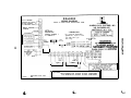
WIRING DIAGRAM .......................................14
ALARM LOCK
0 ALARM LOCK 1990
Alarm Lock Systems, Inc., 34 5 Bayview Avenue, Amityville, New York 11701
Call Toll Free : 800~ALA-LOCK (800-252-5625) FAX: 516-789-3383
WI482 6190
DESCRIPTION
The EAGLE 6000 is a microcomputer based six-zone residential control panel with
provisions for Panic and a variety of reporting features. The system is contained within a
wall-mounted enclosure and includes an integral digital communicator and a multifunction
keypad with numeric display.
The keypad will accept up to four programmable Arm/Disarm Codes to arm and disarm the
control panel. The keypad also serves as a programmer for code entry and feature selection.
Two programming modes enhance system flexibility: the Dealer mode provides full feature
customization, while the User mode allows limited programming for those features most likely
to be changed or used only occasionally. The unit’s nonvolatile EEPROM memory will permanently store the program, keypad codes, and transmission information, even after a lengthy
power failure.
SPECIFICATIONS
Operating Temperature:
Input Power:
Recommended Transformers:
Loop Voltage:
Loop Current:
Loop Resistance:
Alarm Outputs
Relay Output:
Contact Ratings:
Auxiliary Output:
Combined Standby Current:
Remote Station
Current:
Maximum Number:
Recommended Battery:
Standby Time:
Fuses
Aux. Power/Remote Power:
Alarm Output:
Housing Dimensions:
Shipping Weight:
O-49 “C (32-120 OF)
16Vac, Class 2 step-down transformer
ALTR1614 (14.4VA) or ALTR1620 (20VA)
10 to 13Vdc
5.5mA
300 ohms max. series resistance/loop
12Vdc, 1.0A maximum
24Vdc/2A (resistive);
Relay Output selectable for dry contacts
12Vdc regulated
(Remote Power + Auxiliary Output)
300mA maximum with ALTR1614 and 4AH battery
45OmA maximum with ALTR1620 and 6AH battery
25mA typ.
5
4AH Rechargeable, sealed lead-acid
4 hours minimum at maximum combined standby current
lA, 1AG (F2)
3A, 1AG (Fl)
11.2 x 12.3 x 3.1”, HxWxD
(28.4 x 31.2 x 7.8cm, HxWxD)
Approx. 7 lb (3.1kg)
2
INSTALLATION
Note : For operation of keypad controls and indicators, refer to User’s Guide (01135).
Mounting. Choose mounting location accessible to (a) continuously-powered ac source, (b)
cold-water-pipe ground ideally no further away than 10 feet, and (c) telephone lines (keep
telephone wiring away from speaker wires). Remove knockouts for cables. Place control panel
at convenient viewing height. The chassis may be used as a template to mark the mounting
holes. It will accommodate a variety of mounting screw sizes; #10 Type A screws are
recommended.
A keypad should be placed near the exit/entry door. If another keypad is to be located at
control panel, remove the knockout in the control-panel door. If a keypad is not mounted in
the front door, affix the self-adhesive logo onto the keypad knockout. The front door is secured
by means of the three Phillips-head sheet metal screws supplied.
Grounding. Connect control-panel grounding screw to metal cold water pipe. Do not use gas
pipe, plastic pipe or ac ground connections. Use at least 16-gauge wire. Make run as short and
direct as possible, with no sharp bends in wire.
Power-Up Sequence (1)
. Connect ac power. (2) Install backup battery (required). (3) Connect
telephone cord to RJ31X jack.
AC-Failure Indication. Loss of ac power is indicated by all LEDs flashing simultaneously.
Holding down Key [9] (until beep) will temporarily reset LEDs to check zone status and to
arm system.
Arming & Disarming System. When any Arm/Disarm Code is entered, Armed LED will
either come on (control panel armed) or go off (control panel disarmed). If a wrong code is
entered, system will fail to respond. Wait at least 2 seconds before trying again.
Keypad Panic . Tripped by simultaneously pressing Keys [*] and [#].
Testing The System .After installation is completed, test system as follows:
(1) Call central station to inform them of test. (2) Initiate an alarm, preferably on a zone that
activates a steady siren. (3) Verify proper signalling, and call central station to confirm their
receipt of a good transmission.
PROGRAMMING
NOTE: Instructions for User Keypad Programming are given in the User’s Guide (01135).
Default Program. The following default program is factory installed. It is the installer’s
responsibility to change, add, and/or delete features, in accordance with these programming
instructions to customize the system to suit the application and conform to local codes.
Arm/Disarm Code 1: 1,2,3,4
Entry Delay: 20 seconds
Exit Delay: 20 seconds
Auto-Bypass: Zones l-6
Selective Bypass: Zones l-4
Group Bypass: Zones 2,3
24-Hour Protection: Zone 5
Auto-Reset: Zones l-6
Line-Seizure Time*: 2 seconds
Alarm Output: Zones l-6
Anti-Jam Time*: 15 seconds
Output Time-Out: 10 minutes
Redial Delay Time*: 4 seconds
Pulsing Output: Zone 6
Wait for Handshake*: 35 seconds
50mS Loop Response: Zone 5
Redial Attempts*: 9
Enable Keypad Panic on Zone 5
Auto-Reset After Output 1 Timeout
*Must be programmed for communication
3
Dealer Keypad Programming. To access Dealer Program Mode, connect jumper between
Terminals 3 and 6. Hold down Key [8] until all LEDs light. Keypad now functions as follows:
Key [ 1]:
Fy [iI:.
Keys [*] and [#]:
Advances character in display (1-9, 0, b, C, d, E, and F).
Clears display.
Advances display to next section of a multisection location.
Exits Program Mode (with jumper removed from Terminals 3 & 6).
Note: Do not remove power while in the Program Mode.
Access feature to be programmed by entering its address (see Keypad Programming Sheet).
A beep will sound, indicating that feature is ready to be programmed. Enter required data
using Key [1]. If number displayed is wrong, press Key [2] to clear display. Use Key [3] to
advance to next digit of a multidigit address. After programming is completed, remove jumper
between Terminals 3 and 6, then press Keys [ *] and [#] to exit the Program Mode. (Caution:
Pressing them again - after the LEDs go out - will activate Panic!)
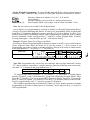
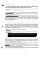
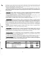
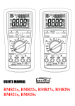
Example: Program Zones l-6 to Report on Alarm.
Referring to Keypad Programming Sheet, Report on Alarm is at B29, a two-section location.
Circle respective data values for Zones l-6 (1,2,4,8 for section 1; 1, 2 for section 2) on
programming sheet, part of which is reproduced below. Add up each section to obtain entries
to be programmed ("15" for section 1: “3” for section 2).
FEATURE
ZONE
1(2(314
B29
REPORT ON ALARM
5
CLO CLO/OPN BY USER
OPN 1 1 2 1 3 1 4
B45
B45
11214
11214l8
1 6
B29
mh5-MiIlmmIm
I
I
Sect. 1
Sect.2
I
Note: The programmed entry can be only one character, thus two-digit data totals (such as
"15", above) must be converted to a single character. From the following conversion chart,
note that “15” is displayed and programmed as an “F”.
Entry Total:
Display:
10
0
11
b
12
C
13
d
14
E
15
F,
To program data entries obtained (“F” for section 1; “3” for section 2), install jumper
between Terminals 3 and 6. Hold down Key [8] until all LEDs light (Program Mode). Press
Keys [B], [2], then Key [9] to access location B29 (Report on Alarm). Press Key [1] repeatedly
until “F” (entry for section 1) is displayed. Press Key [3] to advance display to next section.
Press Key [1] repeatedly until “3” (entry for section 2) is displayed.
This completes programming for location B29. Either (a) access another location to continue
programming or (b) remove jumper between Terminals 3 and 6 and press Keys [*] and [#] to
exit Program Mode.
4
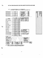
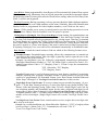
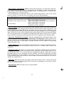
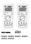
KEYPAD PROGRAMMING RECORD SHEET FOR THE EAGLE 6000
Communicator Transmission Information
NO Lou
ZDNE
_, 1
2
3
4
5
6 AC BAT _
B21 B22 B23 B24 B25 B26 B41 B 4 2
Single Digit-->
3
Extended/Two
o Digit-->_
6-8
ALARM/TROUBLE CODES
RESTORE CODES
OPENING/CLOSING CODES
Cm
Single Digit-->
SUBSCRIBER I.D. NUMBERS
Force
Ad
Jzi
mg
Must be programmed if
Closings are reported.
Telephone #2
Telephone #1
Alarm I.D.
B51
I,,,,_
_______~~~~~~____~~~~~~~~~~~~~~~~~~~~-~ __________________________~_______~~~~~~~~~~~~~~~~~~~
Format
Pre-Dial Access Dial-Tone
Handshake.
6
PROGRAMMING GUIDE
The following guide describes the programmable options and provides important information on required programming. Entries are arranged in alphabetical order.
Abort Delav. Delay period that allows cancellation of central-station report This is done by
disarming control panel within delay period. (If selected for a 24-Hour Zone, cause of alarm
condition must be removed before disarming panel.)
AC-Failure Reporting If ac is removed from control panel, all LEDs will flash simultaneously.
To arm, first press Key [9]. If programmed for Report On Alarm, report will be delayed for 1
hour. Restores will report immediately.
Access Number for Outside Line. Some telephone systems require one digit to access an
outside line before telephone number can be dialed. Also, first dial tone encountered (prior
to access number) may have a frequency different from that of accessed dial tone (440Hz).
One or more 4-second Pre-Dial Delay “d”s may be entered before the access number instead
of a dial tone with frequency “E”.
If subscriber’s system uses an access number, ask telephone-equipment supplier if dial tone
other than 440Hz is received prior to dialing access number. If communicator must delay
before dialing access number instead of attempting to recognize dial tone, find out how many
4-second delays must be programmed.
For each telephone, (a) enter the Dial-Tone Detection “E” or Pre-Dial Delay “D” in the
first location. Enter any extra "D"s that may be required starting in the second location. (b)
Enter the access number digit in the second location or the next available location thereafter.
(c) Starting in the first available location after the access number, enter any Pre-Dial Delay
"D"s needed before the second dial tone; the Dial-Tone Detection “E” for the second dial-tone
frequency; then the telephone number.
Alarm Codes. See Data Format: Single Digit Event Code
Alarm Outputs. The following table summarizes wiring and programming for signalling an
alarm in typical installations. See Time Selection time-outs.
Output
Alarm Output
Pulsing Output
Wiring
7 (-), 8 ( + )
7 (-), 8 ( + )
Remarks
Zone 6 Onlv
Anti-Jam Time. If communicator does not detect a dial tone within 12 seconds, Anti-Jam
feature is activated: communicator will go off line for a preprogrammed anti-jam interval in
order to free telephone circuit from incoming calls, then make another 12-second attempt at
dial-tone detection. If still unsuccessful, communicator will again go off line for 16 seconds,
then proceed to dial anyway. Ask telephone-equipment supplier to determine if a longer time
is required for Anti-Jam feature to function.
To test Anti-Jam feature, call alarm phone line from a different phone line, then activate an
alarm; incoming call should be disconnected by control panel.
Auto-Reset. If a tripped zone is selected for Auto-Reset, it automatically resets itself when
alarm condition is removed. Auto-Reset may be delayed to occur after time-out period by
programming Auto-Reset After Alarm Time-Out.
Zones 1 through 6 not programmed for Auto-Reset will not be able to signal another alarm
until cause of alarm has been removed and panel is disarmed.
7
Auto-BvPass. Zones programmed for Auto-Bypass will be automatically shunted from system
if faulty when arming. Momentary beep at keypad warns that system has been armed without
full protection. Note: Exit/entry door must be closed before arming, otherwise Exit/Entry Zone
(Zone 1) will be auto-bypassed.
Backup Reporting Backup reporting is always present, therefore bbth telephone numbers
must be programmed, even if both numbers are the same. (Similarly, Subscriber Identification
Numbers must be programmed for both telephone numbers, even if both are the same.)
Batterv, 12Vdc standby power source in control panel to provide backup protection in event
of a power loss. Battery must be installed, even if ac power is present.
Closing Report: Closing Bv User: Force-Arm Report Upon arming, the communicator can
transmit either a Closing Report or a Force-Arm Report. Note that both Closing Code and
Force-Arm Code locations must be programmed for any closing report. Therefore, to transmit
a Closing Report only, repeat the Closing Code in the Force-Arm locations. If Closing and
Force-Arm Codes are different, the communicator will transmit a Closing Report each time
the panel is armed, or a Force-Arm Report if the panel is armed with an auto-bypassed zone.
If reporting Closing by User, user code will be transmitted automatically in Extended Format.
Data Format, Consult the central station to find out which of the following formats to use.
Extended Format. Extended-format reporting allows the communicator to transmit an
extra digit to the central station. This extra digit is generally used to report the user or the
zone on which the event occurred.
Example. An installation uses the following programmed transmission information:
Subscriber Identification Number is “789”; an Alarm Code is selected for Zone 1; Extended Format Alarm Code is “31” (Burglary, Zone 1). If Zone 1 trips, the communicator
will transmit:
7893 - Subscriber “789” Burglary
3331- Burglary, Zone 1
Extended Format may be used with most receivers; most that are capable of recognizing
multiple reporting also recognize Extended Format. Central station will specify event
codes to be programmed. For Extended Format, leave Data Format location blank and
follow Steps 2 through 5 of Two-Digit Event-Code Format later in this section.
Single-Digit Event Code Format. If receiver cannot accept extended reporting, (1) program “1” in the Data Format location(s); (2) enter first digit for any Alarm/Trouble Code,
Restore Code and Opening/Closing Codes. Note: To have a Single-Digit Event Code for
one telephone number and Extended Format for the other, program both digits for all
event codes. Follow Steps 2 through 5 of Two-Digit Event Code Format, which follows.
Telephone number with "1" in Data Format location will transmit only first digit; other
number will use both digits. (Single-Digit Format will override Two-Digit Format Location.)
Two-Digit Event Code Format. Some central-station receivers require that a two-digit code
be sent in each report.
Example. In a certain installation, the Alarm Subscriber Number is “1234”; a burglary alarm
occurs on Zone 1 (Alarm Code “31”). Communicator will send “1234 31”.
To use Two-Digit Event Code Format,
8
1. Program "2" in Data Format location(s). See Double Reporting.
2. Enter an Alarm Code for each zone or condition to report on alarm or for a Force-Arm
as follows:
a. Enter first digit of Alarm Code (may be used to indicate alarm type.)
b. Enter second digit of the Alarm Code (may be used to indicate zone.)
3. Repeat Step 2 to enter Restore Codes for each zone selected.
4. If Opening Report or Opening Report After Alarm is selected, enter a two-digit Opening
Code. See Opening Report; Opening Report After Alarm.
5. If Closing Report is selected, enter a two-digit Closing Code. For Force Arm, also enter
a two-digit Force-Arm Code. Note: Single-Digit Format will override Two-Digit Format.
l
Sum-Check Format. Sum Check is a sophisticated data format used to enhance speed and
check accuracy of received transmission. It should be preferred whenever central station
is capable of receiving it.
After transmitting Subscriber Identification Number and event code, communicator sends
a verifying digit that is sum of both. Receiver compares verifying digit with sum of other
two numbers to check transmission accuracy. To select Sum Check, program “4” in Data
Format location(s), and "8" for 2300Hz Handshake.
Day Zone, A Burglary Zone programmed to cause visual and audible indication at keypad if
loop has an open condition only when disarmed. May be used to warn of trouble during the
day, when control panel is not armed. If Day Zone experiences a problem (break in window
foil, for example), Ready LED on keypad will flash, sounder will pulse steadily, and digital
readout will display problem zone(s). Use Reset Key [9] to reset the sounder and display.
Dial-Tone Detection.. At least one entry is usually required for each telephone number used
to ensure that a dial tone is present before communicator dials.
When “E” is programmed before first digit of outside telephone number, communicator
dial-tone detection circuit is set to detect standard 440Hz dial tone. “E” is generally entered
in location just before telephone number.
It may be necessary to program at least one 4-second Pre-Dial Delay before a Dial-Tone
Detection “E”. With certain exchanges, Pre-Dial-Delay "d"s may be used without a Dial-Tone
Detection "E". (See Access Number for Outside Line; Pre-Dial Delay.)
Door Chime. May be used on Zone 1 while disarmed to beep at keypad when zone goes into
trouble. Hold down Key [6] until it beeps to enable or disable.
Double Reporting For Double Reporting, enter Subscriber Identification Numbers for
Telephone 2 and related information. Subscriber Identification Numbers for both Telephones
1 and 2 must be entered, even if they are the same.
Enable Pre-Alarm, Sounds a lo-second warning at keypad if any zone is tripped when armed
with Instant Protection. Gives user time to disarm to avoid sounding a false alarm.
Exit/Entry Delav, Permits exit and entry through Exit/Entry Zone (Zone 1) after system is
armed without setting off an immediate alarm. Exit delay allows time to leave premises after
panel has been armed. Entry delay allows time to enter and disarm. Upon entering, keypad
sounder comes on to remind user to disarm.
Exit- and Entry-Delay times may each be programmed for up to 150 seconds.
9
Exit/entry delay may be cancelled by holding down Key [4] (Instant Protection) prior to
arming (automatically restored upon disarming). A pre-alarm warning may be programmed to
sound at keypad if Exit/Entry Zone is accidentally tripped.
Exit/Entry Follower, Zones 2 and 3 are Exit/Entry Follower Zones; these will ignore
detection during exit delay, and during entry delay only if Exit/Entry Zone is entered first.
Detection devices (e.g. PIRs) along path between keypad and exit/entry door will not signal
an alarm during exit/entry delay under normal conditions. However, if device in Exit/Entry
Follower Zone detects a violation when exit/entry door has not first been entered, there will
be no entry delay and Exit/Entry Follower Zone will go into instant alarm.
If panel is armed with entry delays cancelled (Instant Protection), any violation on Exit/Entry
or Exit/Entry Follower Zone will cause an immediate alarm.
Force Arm See Closing Report
Group Bypass Removal of a preset group of zones from the system. Group Bypass is often
used to deactivate some or all interior zones simultaneously so that user may move freely
throughout premises but still be protected from intrusion through armed perimeter zones.
Zones are group-bypassed by pressing the Bypass Key [B] twice. (Bypass LED on keypad
will light.) Holding down Key [2] will display zones bypassed. When panel is disarmed, all
bypassed zones automatically revert to non-bypassed zones.
Loon Response Loop response is the amount of time that a normally-closed circuit must
remain open, or a normally-open circuit must remain closed, to trigger an alarm. The slower
the loop response, the more immune the system will be to intermittents (swingers). Selectable
loop-response times are:
750mS (.75 sec.): Slowest loop-response time, recommended for use with magnetic contacts, window foil, etc. Unless programmed otherwise, loop- response time will be 750mS
(milliseconds) for all zones.
50mS (.05 sec.): Used for momentary Panic Buttons and area-protection devices, such as
photoelectric eyes, PIRs, floor mats, etc.
1OmS (.010 sec.): An extremely fast loop response used primarily for window bugs, and to
eliminate need for pulse extender.
Low Battery. Alarm will signal when battery terminal voltage drops to ll.OV. A low-battery
condition may report to a central station if programmed.
No AC See AC-Failure Reporting
One-Button Arming Permits quick arming by
requires complete code.)
momentarily
pressing Key [5]. (Disarming still
Opening/Closing Bv User See Closing Report; Opening Report
r Alarm, Opening and closing
reports are generally used in commercial installations. On disarming, communicator can send
an Opening Code (Opening Report), or it may transmit only when control panel is disarmed
after an alarm has occurred (Opening Report After Alarm). Note that Subscriber Identification Numbers and Opening Codes must be entered for either opening report. Program
0
enin
Re
l
10
Opening to report each time the control panel is disarmed. If selecting Opening Report, do
not select Opening Report After Alarm. If reporting Opening by User, user code will be
transmitted automatically in Extended Format.
Program Opening Report After Alarm to report only when disarming after an alarm. This
feature may be used by the central station to verify that the subscriber has responded to the
alarm and disarmed the control panel. If Opening Report After Alarm is selected, do not select
Opening Report.
Panic Zone (Zone 5). When using Zone 5 for Panic, program 24-Hour Protection and Report
On Alarm. Note that if Zone 5 is not programmed for 24-Hour Protection, Panic may still be
activated when disarmed, but “5” will be displayed red LED will flash.
Program Enable Keypad Panic on Zone 5. Panic Zone is accessed by pressing Keys [ *] and
[#]) simultaneously activating communicator to alert central station.
External panic switches may be used on Zone 5 terminals. Do not program Zone 5 for
Restore Report, or a restore will be sent as soon as buttons are released.
Pre-Dial Delav. May be used whenever a delay is required before dialing. It is usually required
to program Dial-Tone Detection, which causes the communicator to wait for a dial tone before
dialing (see Dial-Tone Detection). Certain telephone exchanges send a nonstandard dial tone
that the communicator may not be able to detect. With these exchanges, it is possible to
program Pre-Dial Delay rather than Dial-Tone Detection. This will cause the communicator
to wait for a predetermined period of time before dialing rather than look for a nonstandard
dial tone.
Contact telephone-equipment supplier to find out how long a delay is required before
dialing. Program one “d” for each 4-second delay required.
Priori tv Zone, A zone that will prevent arming if in trouble. If an attempt is made to arm, the
sounder will sound continuously and a “P”wil1 be displayed. Priority condition may be silenced
by disarming. Any zone may be selected as a Priority Zone. A zone in trouble that is neither
a Priority Zone nor an Auto-Bypass Zone will cause an alarm on arming.
Receiver Format, The communicator can be programmed to transmit to any standard
central-station receiver. A receiver format must be entered for each telephone number used,
but a different format may be assigned to each.
Call the central station for each telephone number used to confirm the type of receiver in
use. Select the receiver format entry for each telephone number from the following table.
Reuort on Alarm, When a zone selected to Report on Alarm is tripped, communicator
transmits code for that zone to central station. Enter Alarm Codes for each zone to report on
alarm, even if identical codes are used for different zones.
ENTRY
(BLANK)
1
2
3
4
RECEIVER FORMAT
DATA
FREQ.
Ademco, Silent Knight slow
Radionics, DCI, Franklin slow
Sescoa, Vertex, DCI, Franklin
Radionics fast
Silent Knight fast
1900Hz
18OOHz
1800Hz
1800Hz
l!WOHz
11
DUTY CYCLE INTERDIGIT
TIME
(ON/OFF)
60/40mS
60/40mS
3o/uhns
W12mS
4Of3OmS
600mS
600mS
4OOmS
560mS
Restore Report: Zone Restore, When selecting a Restore Report, (a) Subscriber Alarm/Restore Identification Numbers must be programmed for Telephones 1 and 2; and (b) Restore
Codes must be entered for each zone reporting a restore. If selecting Zone 5 as a Panic Zone,
do not program it for a Restore Report.
The communicator can transmit a report to the central station when a zone or the control
panel is restored. To select the time of reporting, refer to the following table.
PROGRAM:
Instant Auto-Reset
Auto-Reset After Alarm Time-Out
No Auto-Reset
FOR RESTORE REPORT TO BE SENT:
When zone is repaired, or
When control panel is disarmed
When resets (alarm times out and zone repaired), or
When control panel is disarmed
When control panel is disarmed
(regardless of zone condition)
Selective Bypass Removal of one particular zone from the system. Any or all of Zones 1-6
programmed for Selective Bypass may be removed, but each must be removed separately. This
is accomplished by pressing Bypass Key [B] followed by the zone number. When the control
panel is subsequently disarmed, all bypassed zones will automatically revert to non-bypassed
zones. When one or more zones is bypassed, the yellow Bypass LED on the keypad will light.
The zones bypassed may be confirmed by holding down the DISPLAY BYPASS Key [2] until it
beeps; with the key depressed, the bypassed zones will be displayed on the digital readout.
Subscriber Identification Numbers, Must be programmed for each phone number. See
Report on Alarm; Restore Report; Opening Report; Closing Report. Note: Starting at the
left-most location, enter at least 3 digits for each Subscriber Identification Number, even if
the first two are zeros. A fourth digit is available for those receivers capable of recognizing
4-digit subscriber codes.
Swinger Shutdown,To prevent swingers (intermittents) from causing repeated false alarms,
Zones 1 through 6 with Auto-Reset will only reset twice (3 alarms) until rearmed. See
Auto-Reset.
Teleuhone Numbers,To report to a central station, Telephones 1 and 2 must be programmed.
The telephone number will be preceded by at least one Dial-Tone Detection entry (“E”) or
Pre-Dial Delay entry (“d”) to ensure that the communicator detects a dial tone or waits a
reasonable time to access a telephone line before dialing. (See Dial-Tone Detection; Pre-Dial
Delay.) Furthermore, private telephone systems may require a separate Dial-Tone Detection
or Pre-Dial Delay digit, followed by an Access Number to obtain an outside line. (See Access
Number for Outside Line.)
Time-Out. Time-Out specifies the length of time that an alarm, alert, or delay will remain
active. Abort-Delay time and Burglary Time-Out must be programmed, or the feature will not
activate. See Time Selection.
Time Selection, The following times are programmable:
12
Time
Abort Delay (See Note 1)
Exit Delay (See Note 1)
Entry Delay (See Note 1)
Relay Time-Out (See Note 2)
Units
Max. Programmable Time
-seconds
seconds
seconds
minutes
75 seconds
150 seconds
150 seconds
75 minutes
Notes:
1. If time location left blank, feature does not activate.
2. If time location left blank, feature remains active until system disarmed.
Trouble. An abnormal zone condition (a break in loop). Trouble on a Burglary Zone is
indicated by a sounder beep on arming (does not apply to selective- or group-bypassed zones).
If Auto-Bypass has been removed from a Burglary Zone, that zone will go into alarm on
arming.
A Day-Zone trouble is indicated by a flashing Ready LED and a pulsing sounder; the digital
readout displays the troubled zone(s). Keypad is reset by Key [9].
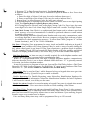
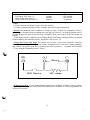
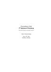
Voltage Open Loop NOL Lug). To convert one or more zones from normally closed to
normally open, install a 330-ohm VOL resistor (supplied) across each zone’s input terminals,
and connect a normally-open device between the zone’s positive ( + ) terminal and Terminal
17. See example, illustrating Zone 5, below.
(-)
Zone 5-a
330 ohms
N/O Device
24-Hour Protection, A zone that provides protection at all times, whether or not system is
armed. Neither Ready nor Armed LED will indicate the condition of a zone programmed for
24-Hour Protection.
13
EGL6000
AC IN 16V/60Hz
ALTR1614 OR ALTR162
DO NOT CONNECT
TO SWITCHED OUTLE
WIRING DIAGRAM
REFER TO INSTALLATION INSTRUCTIONS w1482
ALARM L O C K
ALARM LOCK SYSTEMS, INC.
345 BAYVIEW AVE.
AMITYVILLE, N.Y. 11701
DEALER PROGRAM
TERMINAL
FOR DEALER
PROGRAM MODE
CONNECT TERMINAL 3
TO TERMINAL 6
IMPORTANT
For continued protectlon
agalnst fire, r e p l a c e f u s e s
o n l y with s a n e t y p e
and rating.
E3 0 GS LUG
F2
LINES PRIOR TO SERVICING
I
I
ZONE 2
I
I
1
ZONE 1
I
ZONE 5
1
ZONE 4
I
I
J
(VOL)‘
,
* AUX P O W E R
LA807
0 ALARM LOCK 1990
300mA MAXIMUM WITH OPTIONAL ALTR1614 TRANSFORMER
450mA MAXIMUM WITH OPTIONAL ALTR1620 TRANSFORMER
ALARM LOCK LIMITED WARRANTY
ALARM LOCK Systems, Inc. (ALARM LOCK) warrants its products to be free from manufacturing
defects in materials and workmanship for fifteen
months following the date of manufacture. ALARM
LOCK will, within said period, at its option, repair or
replace any product failing to operate, without charge
to the original purchaser or user.
diminished or affected by, and no obligation or liability
shall arise or grow out of, Seller’s rendering of technical
advice or service in connection with Buyer’s order of
the goods furnished hereunder.
In case of defect, contact the security professional
who installed and maintains your security system.
ALARM LOCK shall have no obligation under this warranty, or otherwise, if the product has been repaired by
others, improperly installed, improperly used, abused,
altered, damaged, subjected to accident, nuisance,
flood, fire or acts of God, or on which any serial numbers have been altered, defaced or removed. ALARM
LOCK will not be responsible for any dismantling, reassembly or reinstallation charges.
Warning: Despite frequent testing, and due to, but
not limited to, any or all of the following: criminal
tampering, electrical or communications disruption, it
is possible for the system to fail to perform as expected.
ALARM LOCK does not represent that the product/systern may not be compromised or circumvented; or that
the product or system will prevent any personal injury
or property loss by burglary, robbery, fire or otherwise;
nor that the product or system will in all cases provide
adequate warning or protection. A properly installed
and maintained alarm or lock may only reduce risk of
burglary, robbery, fire or otherwise but it is not insurance or a guarantee that these events will not occur.
CONSEQUENTLY, SELLER SHALL HAVE NO
LIABILITY FOR ANY PERSONAL INJURY, PROPERTY
DAMAGE, OR OTHER LOSS BASED ON A CLAIM THE
PRODUCT FAILED TO GIVE WARNING. Therefore, the
installer should in turn advise the consumer, and the
consumer is hereby advised, to take any and all
precautions for his or her safety including but not
limited to, fleeing the premises and calling police or fire
department, in order to mitigate the possibilities of
harm and/or damage.
In order to exercise the warranty, the product must
be returned by the user or purchaser, shipping costs
prepaid and insured to ALARM LOCK. After repair or
replacement, ALARM LOCK assumes the cost of
returning products under warranty.
There are no warranties, express or implied, which
extend beyond the description on the face thereof.
There is no express or implied warranty of merchantability or a warranty of fitness for a particular purpose.
Additionally, this warranty is in lieu of all other obligations or liabilities on the part of ALARM LOCK.
Any action for breach of warranty, including but not
limited to any implied warranty or merchantability,
must be brought within the six months following the
end of the warranty period. In no case shall ALARM
LOCK be liable to anyone for any consequential or
incidental damages for breach of this or any other
warranty, express or implied, even if the loss or
damage is caused by the seller’s own negligence or
fault.
This warranty contains the entire warranty. It is the
sole warranty and any prior agreements or representations, whether oral or written, are either merged
herein or are expressly cancelled. ALARM LOCK
neither assumes, nor authorizes any other person purporting to act on its behalf to modify, to change, or to
assume for it, any other warranty or liability concerning
its products.
In no event shall ALARM LOCK be liable for an
amount in excess of ALARM LOCK’s original selling
price of the product, for the loss or damage, whether
direct, indirect, incidental, consequential, or otherwise
arising out of any failure of the product. Seller’s warranty, as hereinabove set forth, shall not be enlarged,
ALARM LOCK RECOMMENDS THAT THE ENTIRE
SYSTEM BE COMPLETELY TESTED WEEKLY.
ALARM LOCK is not an insurer of either the property
or safety of the user’s family or employees, and limits
its liability for any loss or damage including incidental
or consequential damages to ALARM LOCK’s original
selling price of the product regardless of the cause of
such loss or damage. If the user wishes to protect itself
to a greater extent, ALARM LOCK will, at user’s sole
cost and expense, obtain an insurance policy to
protect the user, supplemental to user’s own policy, at
a premium to be determined by ALARM LOCK’s insurer
upon written notice from user by Certified Mail, Return
Receipt Requested, to ALARM LOCK’s home office
address, and upon payment of the annual premium
cost by user.
This warranty shall be construed according to the
laws of the State of New York. Some states do not allow
limitations on how long an implied Warranty lasts or do
not allow the exclusion or limitation of incidental or
consequential damages, or differentiate in their treatment of limitations of liability for ordinary or gross
negligence, so the above limitations or exclusions may
not apply to you. This Warranty gives you specific legal
rights and you may also have other rights which vary
from state to state.