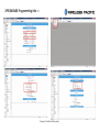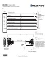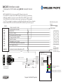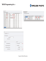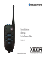
1
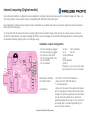
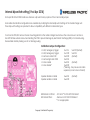
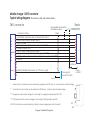
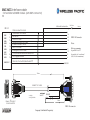
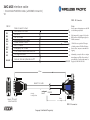
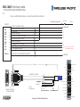
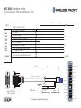
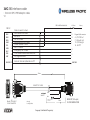
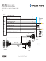
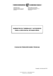
Installation
Set-up
Interface cables
Revision 18
Company Confidential Proprietary
Before you start!
X10DR has been designed to allow simple connectivity to most radio models from those dating back from the 90’s to the most current digital models from most professional radio manufacturers. Understanding the basic connectivity will allow you to successfully
connect to just about any wireless radio device, or to allied wired radio control consoles. The following describes the pin out connectivity of the X10DR mobile charger’s 15 pin DB15 connector. Note: pins not described are used for factory set-up and should not
have DC voltages or grounds applied to them otherwise the device may be damaged or may cause incorrect operation.
Pin 1. Switched B+ In: Used to automatically turn on/off X10DR by sensing the host radio’s status. Normally, this pin connects to a host
radio’s switched B+ output, if available (no current required), if not, the installer should supply a manual on/off switch for user activation of the unit. Note: The speaker microphone’s battery will still charge when the switched B+ is removed.
Pin 2. Transmit Mic Audio Out: This should connect to the host mobile’s transmit audio input. This is the audio from the Wireless Microphone that is to be transmitted over the host mobile radio’s transmitter. It is factory set for approx 80mV RMS. This can be adjusted up
to about 800mV by carefully adjusting the radio audio output VR1 trimpot. (Subject to factory pre-programmed settings. The maximum level can be reset electronically by use of the X10DR Programming kit.)
Pin 3. Radio Mic Lo: This connects to the host mobile’s microphone audio ground. Note: on some TDMA digital radios this pin may be
best connected to only the shield of the interface cable. This is due to TDMA noise that may be transferred from the host mobile and
appear as noise on the X10DR unit.
Pin 4. Receive Audio In: This should connect to the host mobile’s receive audio output. This audio source should be under the radio’s
squelch control and of a level above 40mVrms. Ideally, it should be sourced pre-volume control but can be post, as long as the host
Pin 5. DC Power In
-
nected to ensure the units can recharge when the host mobile may be turned off.
Pin 6. Ext. PTT Out: This pin provides a switched ground output and should connect to the host mobile radio’s external PTT input.
Some radio models have active high PTT inputs. Those models will require the use of special interface cables that allow the X10DR
output to be inverted to an active high.
Company Confidential Proprietary
-
Pin 7. Emergency Out: This output is intended to connect to the host mobile radio’s emergency input. It is normally provides an active switched ground (<50mA sink) but can be jumpered to be active open circuit. The time held low (or high) is the exact time
that the user presses the Emergency button. This output could be used for other functions such as to trigger the panic function of a
grammed for such.
Pin 8. COR/Squelch/Audio Unmute In: This input is designed to monitor the receive status of the host mobile radio. For best operation
it is driven by an “audio unmute” switched ground output from the host mobile. i.e. an indicator of whenever the host radio’s speaker unmutes. Alternatively, it should be driven by a switched ground output that indicates the radio’s squelch condition. This output
should factor reception of the required correct CTCSS tones, etc. On some radios this output is available as standard, on others it
radios with active high outputs.
On some radio devices a COR output is not available without modifying the host mobile. While this would be desirable, the X10DR
features smart VOX circuitry to adapt its operation in these cases where a radio COR is not available. In some mobiles there is a DC
shift on the radio’s speaker output terminal whenever the radio unmutes, which can be used as a COR input. Making use of such
taken to NEVER short a mobile radio’s bridged audio output to ground.
Pin 9. Ground: This pin should connect to DC / Digital ground connection. Note: on digital radios this is usually NEVER audio ground.
Connect to the vehicle’s chassis or a solid DC ground from the host mobile.
Pin 13. Remote PTT In: This pin allows you to provide a remote PTT alternative to transmit Secure Wireless Microphone audio over the
host mobile radio. You may choose to connect to a motorbike’s handle bar PTT, a hidden palm or footswitch or a wireless PTT device.
When a headset is connected to a secure wireless microphone’s Hirose® audio port the microphone sensitivity is normal.
However, if a headset is NOT attached to the Hirose audio port, then grounding pin 13 causes the X10DR to transmit audio with substantially increased mic sensivity. This allows Remote Monitor to be achieved by using a switched output from the host mobile to remotely activate the function. Thus a control room operator could monitor the user’s ambient audio to ascertain the health or safety
of the user. Alternatively, this pin can be used with the XFB Special function box for other specialist applications such as Lone Worker.
Company Confidential Proprietary
Internal Jumpering (Original models)
-
der “blob jumpers” are provided to allow compatibility with different mobile radio types.
SMD type hand soldering.)
ternal PCB. Take extreme care when handling the PCB to prevent damage by electrostatic discharge (ESD) or to internal wiring.
Re-assemble carefully making sure to not damage wiring.
- For active lo radio COR
- For active high radio COR
- For Vox enable
- For Vox disable*
SJ3 Out (default)
SJ3 In
SJ4 In (default)
SJ4 Out
(*Warning - may cause some radio
supervisory tones to be not heard)
** or as appropriate
J3 Default: In
- Remove J3 to prevent the wireless mic speaker from muting when placed inside the mobile
charger. This option is generally recommended
only when the host radio has no internal or
external speaker. Removing J3, may cause the
very busy radio channel.
Company Confidential Proprietary
Internal dip switch setting ( Post Apr 2014)
These dip switch settings are provided to allow compatibility with different mobile radio types.
ternal PCB. Take extreme care when handling the PCB to prevent damage by electrostatic discharge (ESD) or to internal wiring.
Re-assemble carefully making sure to not damage wiring.
- For active lo radio COR
- For active high radio COR
- For Vox enable
- For Vox disable*
Sw3 OFF
(default)
Sw3 ON
Sw4 ON
(default)
Sw4 OFF
(*Warning - may cause some radio
supervisory tones to be not heard)
-Speaker disable in cradle
-Speaker enable in cradle
Sw6 ON
Sw6 OFF
** or as appropriate
Company Confidential Proprietary
(default)
Set Up - Basic Requirements
Radio Programming - VERY IMPORTANT
For correct X10DR operation, the host mobile radio on some occasions will require reprogramming (via its associated FPP/CPS etc)
to enable correct functionality. Read carefully this instruction document to get a complete understanding of the interfacing requirelike PTT, COR (channel busy), emergency trigger and audio level settings to be accessible on the radios rear interface connector.
Incorrect radio settings may cause distortion or noisy audio, the unit to not function or may damage either the X10DR or host radio
Adjusting Levels - VERY IMPORTANT
Installation of the X10DR requires setting of audio levels between the X10DR and the host radio.
-
lips screwdriver (PH1) to carefully adjust the settings. The X10DR is factory set to provide a nominal 80mV audio signal to the host radio’s mic input. This level can be adjusted via VR1 to suit the
particular radios requirement. VR1 should be adjusted (if necessary) to match the audio level &
sary) to set a loud and undistorted receive audio signal on the X10DR unit when receiving from
a service monitor, or another radio. Make sure the X10DR user volume control is on level 4 before
VR1
blue button once). Note: some radios can only provide a volume controlled audio output to the
ing level in the vehicle, and then adjust the X10DR volume to suit.
The X10DR mobile charger’s trimpots are very delicate and extreme care must be taken when adjusting to
prevent physical damage. - NOTE: mechanical damage is not covered by X10DR product warranty!
Company Confidential Proprietary
Mobile charger DB15 connector
Typical wiring diagram (New Generic cable color scheme shown)
DB15 connector
User supplied manual off/on
(if desired/required)
connects to D shell
BLK
BRN
RED
ORG
YEL
DRK GRN
BLU
PUR
GRY
BLK-WH
1
2
3
4
5
6
7
8
9
10
11
12
13
14
15
Radio
connector
Shield
Switched B+ sense from radio or manual off/on switch
Ext Mic audio to radio - default* 80mV)
Mic Lo to radio
Received audio input from radio - default >400mV)**
Power ( nominal +12V)
Ext PTT output to radio (active: sw grd)
Emergency output to radio (active: sw grd - default***)
COR squelch / audio unmute from radio (active: sw grd - default****)
Ground
1A FB fuse
Remote/handlebar/footswitch, etc. PTT input (sw grd)
User supplied
remote PTT switch
Ground
*
Audio output to host mobile can be increased by progammer/via VR1 trim pot - use hole in base of mobile charger.
**
Audio input from host mobile can be adjusted via VR2 trim pot - use hole in base of mobile charger.
*** Emergency output can be changed to “active high” by swapping solder jumpers SP1 & SP2.
**** COR/Squelch/unmute can be changed to “active high” by fitting solder jumper SP3.
NOTE: Pin 5 should be connected directly to battery to ensure charging when unit is turned off.
VR1
VR2
Company Confidential Proprietary
Power
6-15VDC
XMC-GEN Interface cable - Original generic cable
version. Note: different wiring colour scheme.
: for any mobile
V0
1A FB fuse
Battery
S
DB15 F
BLK
BLK-WH
BRN
BRN-WH
RED
RED-WH
ORG
YEL
DRK GRN
1
WH
13
Drain connects to shell
Switched B+ from radio
Ext Mic Hi
Mic Lo to radio
Received audio from radio
3
4
5
6
7
8
9
Fuseholder NOT supplied
Ext PTT to radio
Emergency out to radio
COR/ Audio unmute from radio
DC/ Digital Ground
Remote/ footswitch/Handle bar PTT
150cm
WG*15C +ADB
"J1"
FEMALE, 15-CONTACT
D-SUB CONNECTOR
X10DR
¥
Company Confidential Proprietary
XMC-GEN Interface cable - Current version:
for any mobile
V1
DB15 F
BLK
BRN
RED
ORG
YEL
DRK GRN
BLU
PUR
GRY
1
BLK-WH
13
Drain connects to shell
Switched B+ from radio
Ext Mic Hi
Mic Lo to radio
Received audio from radio
3
4
5
6
7
8
9
Ext PTT to radio
Emergency out to radio
COR/ Audio unmute from radio
DC/ Digital Ground
Remote/ footswitch/Handle bar PTT
150cm
WG*15C +ADB
unstripped
Drain
BLK-WH(new)
Red
"J1"
FEMALE, 15-CONTACT
D-SUB CONNECTOR
X10DR
¥
In-line fuseholder
1A FB fuse
Company Confidential Proprietary
50cm
1A FB fuse
S
RED 22AWG with fuseholder
Battery
XMC-XTL Interface cable
: for Motorola APX/XTL series
V1
RED 22AWG with fuseholder
Battery
S
DB15 F
BLK
BRN
RED
ORG
YEL
GRN
BLU
PUR
GRY
1A FB fuse
Drain connects to shell
Switched B+ from radio
Ext Mic Hi
Mic Lo to radio
Received audio from radio
1
3
4
5
6
7
8
9
14
Ext PTT to radio
Emergency out to radio (N/C)
COR/ Channel activity from radio
DC/ Digital Ground
16
15
13
1
Remote/ footswitch/Handle bar PTT
BLK/WH 13
Emergency operation on
older XTL mobiles
BLK/WH
Connector shown for reference only
- not supplied with XMC-XTL cable
150cm
WG*15C +ADB
unstripped
Drain
BLK/WH
Red
"J1"
FEMALE, 15-CONTACT
D-SUB CONNECTOR
X10DR
¥
In-line fuseholder
1A FB fuse
Company Confidential Proprietary
50cm
XMC-MCS Interface cable
V0
DB15 F
BLK
BRN
RED
ORG
YEL
GRN
BLU
PUR
GRY
Drain connects to shell
Switched B+ from radio
Ext Mic Hi
Mic Lo to radio
Received audio from radio
1
3
4
5
6
7
8
9
14
10
11
Ext PTT to radio
Emergency out to radio
COR/ Audio unmute from radio/TOR
DC/ Digital Ground
DB25 -M Connector
Notes:
13
8
4
Program Pin 21 for PTT
Program Pin 8 for “car radio mute”.
(F4, F3, F2, F9 from main menu)
BLK/WH
150cm
WG*15C +ADB
unstripped
"J1"
FEMALE, 15-CONTACT
D-SUB CONNECTOR
X10DR
¥
Battery
Radio programming
Remote/ footswitch/Handle bar PTT
BLK/WH 13
1A FB fuse
S
RED 22AWG with fuseholder
* or Purple
** or Purple /White
BLK/WH
Red
50cm
DB25 -M connector
Company Confidential Proprietary
XMC-M16 Interface cable
: for Motorola MTM800/GM360/MCX/PM400/CDM etc.
series
V0
RED 22AWG with fuseholder
Battery
S
DB15 F
BLK
BRN
RED
ORG
YEL
GRN
BLU
PUR
GRY
1A FB fuse
Drain connects to shell
Switched B+ from radio
Ext Mic Hi
Mic Lo to radio
Received audio from radio
1
3
4
5
6
7
8
9
13
7
11
Ext PTT to radio
Emergency out to radio
COR/ Audio unmute from radio
DC/ Digital Ground
3
9
8***
7
Remote/ footswitch/Handle bar PTT
BLK/WH 13
BLK/WH
Note: Motorola have over the years
used the 16 pin connector on a wide
variety of models.You should check the
radio programming and or jumpering to
ensure correct operation of the X10DR
unit.
150cm
***Pin 8 : may be programmable for
COR depending on particular model.
WG*15C +ADB
unstripped
# Note: On MTM800 series TETRA radios
Pin 8 - yellow wire MUST be removed
from 16 oin connector and insulated.
Drain
BLK/WH
Pin 9 may need programming for Emergency operation.
Red
"J1"
FEMALE, 15-CONTACT
D-SUB CONNECTOR
X10DR
¥
* or Purple
** or Purple /White
In-line fuseholder
1A FB fuse
Company Confidential Proprietary
50cm
Pin 11: Should be set for pre-emphasis
and gated where applicable by either
programming or hardware jumper
where applicable.
BEWARE: Consult GTX/LTS manual before attempting connection.
XMC-M25 Interface cable
V0
DB25 -M Connector
DB15 F
1
3
4
5
6
7
8
9
Need to remove shorting jumper on radio TIB
to enable Emergency function.
S
BLK
BRN
RED
ORG
YEL
GRN
BLU
PUR
GRY
Notes:
Drain connects to shell
Switched B+ from radio
Ext Mic Hi
Mic Lo to radio
Received audio from radio
Ext PTT to radio
Emergency out to radio
COR/ Audio unmute from radio/TOR
DC/ Digital Ground
1
13
**
Remote/ footswitch/Handle bar PTT
BLK/WH 13
1A FB fuse
15
10
6
BLK/WH
SJ1&2 may need to be swapped on X-ponder
PCB if radio needs NC Emergency input. See
X10DR user manual.
**PM1500 does not provide a COR output.
so default operation of X10DR will be using
Rx voice detect. (may cause some small voice
clipping)
Alternatively, you may be able to re-configure
internal jumpers on TIB to allow a switched
ground indicate of “radio speaker unmute” to
be applied to DB25 Pin 5 for COR.
150cm
WG*15C +ADB
unstripped
"J1"
FEMALE, 15-CONTACT
D-SUB CONNECTOR
X10DR
* or Purple
** or Purple /White
BLK/WH
50cm
DB25 -M connector
¥
Company Confidential Proprietary
XMC-M26T Interface cable
: for Motorola Tetra MTM5400 series
V1
( If you use XMC-M26 cable, you must move Mic Hi and Mic Lo
RED 22AWG with fuseholder
Battery
S
DB15 F
BLK
BRN
RED
ORG
YEL
GRN
BLU
PUR
GRY
1A FB fuse
Drain connects to shell
Switched B+ from radio
Ext Mic Hi
Mic Lo to radio
Received audio from radio
1
3
4
5
6
7
8
9
Drain/shield
7
13
16
14
Ext PTT to radio
Emergency out to radio
COR/ Audio unmute from radio
DC/ Digital Ground
17
N/C
8
Remote/ footswitch/Handle bar PTT
BLK/WH 13
(do not cut - leave wire
for possible future use)
BLK/WH
Spkr+
12
Power Ground
10
14
Rx Audio
16
Audio Ground
18
Ground
20
GP5_6
22
GP5_7
24
GP5_8
26
Ign Sense
MAP_ID_1
8
Company Confidential Proprietary
25
X10DR
23
Emerg Sw
¥
21
GP5_3 (Chan Act)
6
GP5_2 (Monitor)
4
50cm
19
"J1"
FEMALE, 15-CONTACT
D-SUB CONNECTOR
In-line fuseholder
1A FB fuse
17
Red
* or Purple
** or Purple /White
GP5_1 (PTT)
15
Aux Audio Out 2 / TxD
BLK/WH
13
Drain
USB / MAP_ID Ground
11
Tx Audio
unstripped
D-
9
Spkr-
WG*15C +ADB
7
SW B+
5
MAP_ID_2
2
Vbus
3
150cm
1
D+
VIP_1 (Ext Alarm)
XMC-M26 Interface cable
: for Motorola Trbo XPR and DM3600 etc series
V0
RED 22AWG with fuseholder
Battery
S
DB15 F
BLK
BRN
RED
ORG
YEL
GRN
BLU
PUR
GRY
1A FB fuse
Drain connects to shell
Switched B+ from radio
Ext Mic Hi
Mic Lo to radio
Received audio from radio
1
3
4
5
6
7
8
9
7
11
14
Ext PTT to radio
Emergency out to radio
COR/ Audio unmute from radio
DC/ Digital Ground
17
8
Remote/ footswitch/Handle bar PTT
BLK/WH 13
BLK/WH
Ground
18
Ground
20
GP5_6
22
GP5_7
24
GP5_8
26
Ign Sense
Rx Audio
16
Company Confidential Proprietary
25
X10DR
23
Emerg Sw
¥
21
GP5_3 (Chan Act)
Audio Ground
14
GP5_2 (Monitor)
Spkr+
12
50cm
Power Ground
10
In-line fuseholder
1A FB fuse
MAP_ID_1
8
* or Purple
** or Purple /White
19
"J1"
FEMALE, 15-CONTACT
D-SUB CONNECTOR
GP5_1 (PTT)
17
Red
USB / MAP_ID Ground
6
Aux Audio Out 2 / TxD
D-
4
Drain
BLK/WH
15
unstripped
13
Aux Audio Out 1 / RxD
11
Tx Audio
9
Spkr-
WG*15C +ADB
7
SW B+
5
MAP_ID_2
2
Vbus
3
150cm
1
D+
VIP_1 (Ext Alarm)
XPR/DM3600 Programming info V0
Company Confidential Proprietary
XMC-K25 Interface cable
V1
RED 22AWG with fuseholder
Battery
S
DB15 F
BLK
BRN
RED
ORG
YEL
GRN
BLU
PUR
GRY
1A FB fuse
Drain connects to shell
Switched B+ from radio
Ext Mic Hi
Mic Lo to radio
Received audio from radio
1
3
4
5
6
7
8
9
8.2k
17
Ext PTT to radio
Emergency out to radio
COR/ Audio unmute from radio/TOR
DC/ Digital Ground
4
8#
X10DR
¥
Notes:
Radio pins 4, 8, & 24 need
programming on NX700
models and some other
Kenwood models.
150cm
Set external Mic sensitivity
for “low”when available in
the field programmer.
WG*15C +ADB
#May need to adjust Emergency TX time settings.
unstripped
"J1"
FEMALE, 15-CONTACT
D-SUB CONNECTOR
DB25 -M Connector
* Some Kenwood radios
use pin 13 for External Mic
7
Hi and requires you to
move the wire from pin 6
BLK-WH in the DB25 and may also
require an internal jumper
in radio. (refer radio specific service manual)
Remote/ footswitch/Handle bar PTT
BLK/WH 13
14
6*
* or Purple
** or Purple /White
BLK/WH
Red
In-line fuseholder
1A FB fuse
Company Confidential Proprietary
50cm
NX700/800 Programming info V0
Company Confidential Proprietary
XMC-K15 Interface cable
: for Kenwood 15 Pin radios/ KCT-19 cable
V0
RED 22AWG with fuseholder
Battery
S
DB15 F
BLK
BRN
RED
ORG
YEL
GRN
BLU
PUR
GRY
1A FB fuse
Drain connects to shell
Switched B+ from radio
Ext Mic Hi
Mic Lo to radio
Received audio from radio
1
3
4
5
6
7
8
9
SHIELD/DRAIN
7
5
Ext PTT to radio
Emergency out to radio
COR/ Audio unmute from radio/TOR
DC/ Digital Ground
8
15
11
6
Remote/ footswitch/Handle bar PTT
BLK/WH 13
Program Radio
FNCs tied to Molex
pins
Pins 8: PTT
Pin 11: TOR
Pin 15: Emegency
BLK/WH
150cm
WG*15C +ADB
unstripped
"J1"
FEMALE, 15-CONTACT
D-SUB CONNECTOR
X10DR
¥
* or Purple
** or Purple /White
Drain
BLK/WH
Red
In-line fuseholder
1A FB fuse
50cm
view from rear (wire insert side)
Company Confidential Proprietary
XMC-K15D Interface cable
V0
DB15 F
BLK
BRN
RED
ORG
YEL
GRN
BLU
PUR
GRY
Drain connects to shell
Switched B+ from radio
Ext Mic Hi
Mic Lo to radio
Received audio from radio
1
3
4
5
6
7
8
9
5
15
4
1
6
7
8
15
8.2K
Ext PTT to radio
Emergency out to radio
COR/ Audio unmute from radio/TOR
DC/ Digital Ground
Remote/ footswitch/Handle bar PTT
BLK/WH 13
BLK/WH
Move chip jumper R796 to R798
150cm
Move chip jumber R797 to R799
TK8360
WG*15C +ADB
unstripped
BLK/WH
"J1"
FEMALE, 15-CONTACT
D-SUB CONNECTOR
50cm
Requires VOX to be disabled on
X10DR cradle : SJ4 out.
A short burst of noise will sound sometimes when pressing PTT. This is because
the Rx audio from the TK radio is not
muted. Alternatively the radio must be
nector connects to the junction R790/
pin 10 of IC706
DB15P D-SUB CONNECTOR
X10DR
RADIO CPS
Program Radio connector
8- I/O COR out
7- I/O Emerg In
6 - I/O Ext PTT In
¥
Company Confidential Proprietary
XMC-K15 Interface cable
: for Kenwood 15 Pin radios using KCT-39 cable/TK7160 etc
V0
NOTE: The XMC-K15 Cable is factory set up for KCT-19 Kenwood interface cable.
To use with KCT-39 you must rewire the XMC-K15 molex 15 pin connector as per the following:
Additionally, you must move two wires in connector CN3 of Kenwood’s KCT-39 cable. (see insert)
Note: X10DR must be set for 200mV mic audio out (pin2) - may require use of XPK programmer.
Note: TK7160 is only capable of providing carrier squelched Rx audio which means if others are sharing the
channel on different CTCSS codes will be heard unless VOX is disabled in X-ponder unit (see page 4).
RED 22AWG with fuseholder
1A FB fuse
S
DB15 F
BLK
BRN
RED
ORG
YEL
GRN
BLU
PUR
GRY
1
BLK/WH
13
Drain connects to shell
Switched B+ from radio
Ext Mic Hi
Mic Lo to radio
Received audio from radio
3
4
5
6
7
8
9
1
5
3
4
Ext PTT to radio
Emergency out to radio
COR/ Audio unmute from radio/TOR
DC/ Digital Ground
7
15
11
3
Remote/ footswitch/Handle bar PTT
KENWOOD
KCT-39 cable assembly
WG*15C +ADB
unstripped
WH
In-line fuseholder
1A FB fuse
X10DR
You must
Program Radio FNCs :
FNC3 =Pins 7 : PTT
FNC7=Pin 11 : TOR
FNC1=Pin 15 : Emergency
1
2
3
4
5
6
7
8
CN2
Drain
1
Red
¥
view from rear (wire insert side)
BLK/WH
150cm
"J1"
FEMALE, 15-CONTACT
D-SUB CONNECTOR
Battery
SHIELD/DRAIN
50cm
Company Confidential Proprietary
3
4
5
6
7
8
9
10
11
CN3
The following wire needs to be
moved in CN3:
-Wire in position 3 move to Position 7
-Wire in position 2 move to Position 4
XMC-K15S Interface cable
V0 : requires use of external speaker
DB15M D-SUB
DB15 F
BLK
BRN
RED
ORG
YEL
GRN
BLU
PUR
GRY
1
BLK/WH
13
Drain connects to shell
Switched B+ from radio
Ext Mic Hi
Mic Lo to radio
Received audio from radio
3
4
5
6
7
8
9
8.2K
Ext PTT to radio
Emergency out to radio
COR/ Audio unmute from radio/TOR
DC/ Digital Ground
Remote/ footswitch/Handle bar PTT
5
15
4
1
6
7
8
15
RADIO CPS
Program Radio connector
8- I/O COR out
7- I/O Emerg In
6 - I/O Ext PTT In
BLK/WH
150cm
TK8360
Plug dual 3.5 “Y” adaptor into radio spk socket. Plug 3.5 plug from XMC into one 3.5 jack
Plug radio external spk into other 3.5 jack.
Set Radio volume control for normal listening
WG*15C +ADB
desired listening level from X10DR Spk Mic.
unstripped
BLK/WH
"J1"
FEMALE, 15-CONTACT
D-SUB CONNECTOR
X10DR
Y adaptor sourcing:
http://www.amazon.com/Headphone-Splitter50cm
¥
Company Confidential Proprietary
similiar. ( can be mono)
XMC-T15 Interface cable
: for Tait TM/7000/8000/9000 Series
V0
RED 22AWG with fuseholder
Battery
S
DB15 F
BLK
BRN
RED
ORG
YEL
GRN
BLU
PUR
GRY
1A FB fuse
Drain connects to shell
Switched B+ from radio
Ext Mic Hi
Mic Lo to radio
Received audio from radio
1
3
4
5
6
7
8
9
8
14
15
13
4
Ext PTT to radio
Emergency out to radio
COR/ Audio unmute from radio/TOR
DC/ Digital Ground
5
10
15
Remote/ footswitch/Handle bar PTT
BLK/WH 13
Program Radio connector
12- GPIO1 PTT in
10- GPIO Busy out
5 - GPIO Emerg in
13 - Audio tap out
14 - Audio Tap In
BLK/WH
PNK or YEL
Ignition sense
150cm
WG*15C +ADB
unstripped
"J1"
FEMALE, 15-CONTACT
D-SUB CONNECTOR
X10DR
¥
* or Purple
** or Purple /White
YEL
BLK/WH
Red
In-line fuseholder
1A FB fuse
Company Confidential Proprietary
50cm
DB15-M
D-SUB CONNECTOR
TM9000 Programming info V0
Company Confidential Proprietary
XMC-i15 Interface cable
: for Icom OPC-1939 adaptor cable
V1
DB15 F
BLK
BRN
RED
ORG
YEL
GRN
BLU
PUR
GRY
Drain connects to shell
Switched B+ from radio
Ext Mic Hi
Mic Lo to radio
Received audio from radio
1
3
4
5
6
7
8
9
15
13
3
7
Ext PTT to radio
Emergency out to radio
COR/ Audio unmute from radio/TOR
DC/ Digital Ground
4 - I/O COR out
7 - AF Audio out
11- I/O Emerg In
14 - Ext PTT
BLK/WH
150cm
WG*15C +ADB
unstripped
WH
Red
"J1"
FEMALE, 15-CONTACT
D-SUB CONNECTOR
X10DR
¥
* or Purple
** or Purple /White
In-line fuseholder
1A FB fuse
Company Confidential Proprietary
50cm
Battery
Program Radio connector
14
4
11
1
Remote/ footswitch/Handle bar PTT
BLK/WH 13
1A FB fuse
S
RED 22AWG with fuseholder
HDB 15P (VGA style)
D-SUB CONNECTOR
XMC-i25 Interface cable
: for Icom IC-F5061/9511 etc
V1
RED 22AWG with fuseholder
1A FB fuse
Battery
S
DB15 F
BLK
BRN
RED
ORG
YEL
DRK GRN
BLU
PUR
GRY
1
BLK-WH
13
Drain connects to shell
Switched B+ from radio
Ext Mic Hi
Mic Lo to radio
Received audio from radio
3
4
5
6
7
8
9
11
8
7
9
Ext PTT to radio
Emergency out to radio
COR/ Audio unmute from radio/TOR
DC/ Digital Ground
19
15
17
14
Remote/ footswitch/Handle bar PTT
Program Radio connector
pin 15: Emergency Input
if available.
Note: ‘coffee bean” N
must be fitted on radio
main board to enable Mic
audio to connect to Pin 8.
BLK/WH
150cm
WG*15C +ADB
unstripped
BLK/WH
Drain
"J1"
FEMALE, 15-CONTACT
D-SUB CONNECTOR
X10DR
¥
* or Purple
** or Purple /White
Red
In-line fuseholder
1A FB fuse
Company Confidential Proprietary
50cm
DB25 -M
D-SUB CONNECTOR
XMC-HXG Interface cable
: for Harris XG100 High tier mobiles
V1
RED 22AWG with fuseholder
1A FB fuse
Battery
S
DB15 F
BLK
BRN
RED
ORG
YEL
DRK GRN
BLU
PUR
GRY
1
BLK-WH
13
Drain connects to shell
Switched B+ from radio
Ext Mic Hi
Mic Lo to radio
Received audio from radio
3
4
5
6
7
8
9
1
5
Ext PTT to radio
Emergency out to radio
COR/ Audio unmute from radio/TOR
DC/ Digital Ground
18 (Needs program for PTT)
7
Remote/ footswitch/Handle bar PTT
BLK/WH
Use XG100 RPM to
select I/O and function
required.
150cm
WG*15C +ADB
unstripped
BLK/WH
Red
"J1"
FEMALE, 15-CONTACT
D-SUB CONNECTOR
X10DR
¥
In-line fuseholder
1A FB fuse
* or Purple
** or Purple /White
Company Confidential Proprietary
50cm
DB44 -M
D-SUB CONNECTOR
XMC-V25 Interface cable
: for Vertex VX5500 etc High tier mobiles
V0
RED 22AWG with fuseholder
S
DB15 F
BLK
BRN
RED
ORG
YEL
GRN
BLU
PUR
GRY
1A FB fuse
Drain connects to shell
Switched B+ from radio
Ext Mic Hi
Mic Lo to radio
Received audio from radio
1
3
4
5
6
7
8
9
14
13
17
Ext PTT to radio
Emergency out to radio
COR/ Audio unmute from radio/TOR
DC/ Digital Ground
11
7 & 18
Remote/ footswitch/Handle bar PTT
BLK/WH 13
BLK/WH
150cm
WG*15C +ADB
unstripped
BLK/WH
Red
"J1"
FEMALE, 15-CONTACT
D-SUB CONNECTOR
X10DR
¥
In-line fuseholder
1A FB fuse
* or Purple
** or Purple /White
Company Confidential Proprietary
50cm
DB25 -M
D-SUB CONNECTOR
Battery
XMC-V15 Interface cable
: for Vertex 15 pin lower tier mobiles
V0
RED 22AWG with fuseholder
1A FB fuse
S
DB15 F
BLK
BRN
RED
ORG
YEL
GRN
BLU
PUR
GRY
1
BLK/WH
13
Drain connects to shell
Switched B+ from radio
Ext Mic Hi
Mic Lo to radio
Received audio from radio
3
4
5
6
7
8
9
4
1
3
Ext PTT to radio
Emergency out to radio
COR/ Audio unmute from radio/TOR
DC/ Digital Ground
6
14
13
15
Remote/ footswitch/Handle bar PTT
BLK/WH
150cm
WG*15C +ADB
unstripped
BLK/WH
Red
"J1"
FEMALE, 15-CONTACT
D-SUB CONNECTOR
X10DR
¥
* or Purple
** or Purple /White
In-line fuseholder
1A FB fuse
Company Confidential Proprietary
50cm
DB15 -M
D-SUB CONNECTOR
Battery
XMC-C26 Interface cable
: for Cassidian TMR880/i mobiles
V1
DB15 F
BLK
BRN
RED
ORG
YEL
GRN
BLU
PUR
GRY
Drain connects to shell
Switched B+ from radio
Ext Mic Hi
Mic Lo to radio
Received audio from radio
1
3
4
5
6
7
8
9
Ext PTT to radio
Emergency out to radio
COR/ Audio unmute from radio/TOR
DC/ Digital Ground
3*&4*
18
Remote/ footswitch/Handle bar PTT
BLK/WH 13
*programmable
radio pins
1:No action 5V
2/:Emerg In
3/Rx Activity
4/Call incoming
1*
BLK/WH
R1
100K
R2
1K
Q1
MOSFET P
150cm
27K K
D1
10V
PTT Out (+10V= PTT active)
to Pin 14 Systems Connector
WG*15C +ADB
unstripped
"J1"
FEMALE, 15-CONTACT
D-SUB CONNECTOR
X10DR
¥
* or Purple
** or Purple /White
BLK/WH
50cm
Company Confidential Proprietary
DB26 -HDM
D-SUB CONNECTOR
XMC-SRM Interface cable:
for Simoco SRM 9000 series mobiles
(adds X10DR Interface cable to an existing SRM power cable)
DB15 F
BLK
Drain connects to shell
Switched B+ from radio
Audio out to radio Ext Mic Hi
Mic Lo to radio
Received audio from radio
1
BLK-WH
GRN
3
4
5
6
7
8
9
WH
13
BRN*
BRN-WH**
RED
RED-WH
ORG
YEL
Drain connects to shell
14
15
Ext PTT to radio
Emergency input
COR/ Audio unmute from radio
DC/ Digital Ground
7
3
8
ORG
Remote/ footswitch/Handle bar PTT
22# BLK 22# RED RED
PUR
24SAWG
RED 24AWG -normally this is ignition sense input, but some SRM9000 models may be
6
13
BLU BLK (Spk socket)
internally modified/jumpered to make this an emergency input. In such cases join RED to
Orange.
RED 24AWG ignition In
ORANGE- Emerg Output
PURPLE - Handle bar PTT
(GREEN not used)
X10DR
¥
"YELLOW"CRIMP
JOINERS FITTED
1
2
Company Confidential Proprietary
RED
BLACK
BLUE
BLACK
DB15 -M
D-SUB CONNECTOR
SRM9000 Programming info V0
Company Confidential Proprietary
XMC-SRG Interface cable:
for Sepura SRG TETRA series mobiles
(add X10DR to an existing SRG power cable)
V1
DB15 F
BLK
Drain connects to shell
Switched B+ from radio
Ext Mic Hi
Mic Lo to radio
Received audio from radio
1
BLK-WH
BRN*
BRN-WH**
RED
RED-WH
ORG
YEL
GRN
RED
3
4
5
6
7
8
9
4
7
6,8 &SH
5
Ext PTT to radio
Emergency out to radio
COR/ Audio unmute from radio/TOR
DC/ Digital Ground
7
15
14
100K
RED
26AWG
RED
PUR
150cm
DB15 -HD-M
D-SUB
WG*15C +ADB
26 AWG
X10DR
13
6
8
3
SPK Conn
GRN
YLW
20cm
SPK Conn
Company Confidential Proprietary
DB15 -F
D-SUB
BLK
BLK
BLU
YLW
Ign sense
DB15 -F
D-SUB
PUR- Not used
YLW -Not used
unstripped
¥
RED
100K
25cm
"J1"
FEMALE, 15-CONTACT
D-SUB CONNECTOR
crimp
crimp
Remote/ footswitch/Handle bar PTT
13
DB15-HD-M
D-SUB
GRN
SRG3900 Programming info V0
Company Confidential Proprietary
BLK
BRN
RED
ORG
YEL
GRN
BLU
PUR
GRY
Drain connects to shell
Switched B+ from radio
Ext Mic Hi
Mic Lo to radio
Received audio from radio
1
3
4
5
6
7
8
9
Ext PTT to radio
Emergency out to radio
COR/ Audio unmute from radio
DC/ Digital Ground
BLK/WH 13
24
12
13
21 ( program for Ext PTT?)
23 ( program for Emergency Input?)
22 ( program for COR/radio unmute?)
1
BLK/WH
150cm
Figure 19 - Remote Mount Extended Option Accessory Cable
19B802554P7
WG*15C +ADB
Drain
WH
Red
In-line fuseholder
1A FB fuse
"J1"
FEMALE, 15-CONTACT
D-SUB CONNECTOR
50cm
WE HAVE NOT TESTED ON HARRIS ORION MOBILE AS
YET BUT BASED ON SUPPLIED DOCUMENTION SHOULD
BE ABLE TO WORK ASSUMING PINS 21,22 1NBD 23 ARE
PROGRAMMABLE AS SHOWN.
* or Purple
** or Purple /White
ORION MOBILE WIRING HARNESS
19
X10DR
¥
Battery
P1 or equivalent or other connectors
i.e. whatever is accessible/practical.
25
Remote/ footswitch/Handle bar PTT
unstripped
S
DB15 F
1A FB fuse
RED 22AWG with fuseholder
te Mount
V0
asic Accessory Cable, at one end, consists of the basic accessories
ctor (P3) and the speaker connector (P2). At the other end is the
P1. P1 will connect to the Option Connector (OPT) which is
ed on the back of the Radio Interface Adapter (RIA). The
ded Option Accessory Cable is the same as the Basic Cable but
he addition of the Extended Option Plug (P4). See Figures 18 and
e 18 - Remote Mount Standard Accessory Cable 19B802554P6
XMC-ORI Interface cable - Harris orion Draft
Company Confidential Proprietary
XMC-H26 Interface cable
: for Hytera MD68x Tetra & 78x DMR mobiles
V1 RED 22AWG with fuseholder
Battery
S
DB15 F
BLK
BRN
RED
ORG
YEL
GRN
BLU
PUR
GRY
1A FB fuse
Drain connects to shell
Switched B+ from radio
Ext Mic Hi
Mic Lo to radio
Received audio from radio
1
3
4
5
6
7
8
9
4
7
17
8
Ext PTT to radio
Emergency out to radio
COR/ Audio unmute/Channel activity
DC/ Digital Ground
16*
14
3*
Remote/ footswitch/Handle bar PTT
BLK/WH 13
*programmable
radio pins
16: PTT : Active Lo
3: Rx Activity (spkr
unmute-channel
activity) : Active Lo
BLK/WH
150cm
WG*15C +ADB
unstripped
WH
Red
"J1"
FEMALE, 15-CONTACT
D-SUB CONNECTOR
X10DR
¥
* or Purple
** or Purple /White
In-line fuseholder
1A FB fuse
Company Confidential Proprietary
50cm
DB26 -HDM
D-SUB CONNECTOR
XMC-T26 Interface cable
: for Teltronic MDT400 mobiles (Draft)
V1
RED 22AWG with fuseholder
BLK
BRN
RED
ORG
YEL
GRN
BLU
PUR
GRY
Battery
S
DB15 F
1A FB fuse
Drain connects to shell
Switched B+ from radio
Ext Mic Hi
Mic Lo to radio
Received audio from radio
1
3
4
5
6
7
8
9
8*
13
9
Ext PTT to radio
Emergency out to radio
COR/ Audio unmute from radio/TOR
DC/ Digital Ground
5
Remote/ footswitch/Handle bar PTT
BLK/WH13
*Requires pressing (phonebook) +
(9) + (7) then setting audio accessory to Handsfree kit
**Requires programming input 2
***Requires programming
BLK/WH
150cm
WG*15C +ADB
unstripped
"J1"
FEMALE, 15-CONTACT
D-SUB CONNECTOR
X10DR
¥
* or Purple
** or Purple /White
BLK/WH
50cm
Company Confidential Proprietary
DB26 -HDM
D-SUB CONNECTOR
XMC-G25 Interface cable
V0
RED 22AWG with fuseholder
1A FB fuse
Battery
S
DB15 F
BLK
BRN
RED
ORG
YEL
GRN
BLU
PUR
GRY
1
BLK/WH
13
Drain connects to shell
Switched B+ from radio
Ext Mic Hi
Mic Lo to radio
Received audio from radio
3
4
5
6
7
8
9
3
11*
6
9
Remote/ footswitch/Handle bar PTT
WH
150cm
WG*15C +ADB
unstripped
WH
Red
X10DR
Notes:
8
Ext PTT to radio
Emergency out to radio
COR/ Audio unmute from radio/TOR
DC/ Digital Ground
"J1"
FEMALE, 15-CONTACT
D-SUB CONNECTOR
DB25 -Female
Connector
7
5
In-line fuseholder
1A FB fuse
¥
Company Confidential Proprietary
50cm
* Radio pin 11 need programming for Emergency
input where available
XMC-R15 Interface cable
: for RELM BENDIX KING GMH/DMH mobiles
V1
DB15 F
BLK
BRN
RED
ORG
YEL
GRN
BLU
PUR
GRY
Drain connects to shell
Switched B+ from radio
Ext Mic Hi
Mic Lo to radio
Received audio from radio
1
3
4
5
6
7
8
9
5
11
6
Ext PTT to radio
Emergency out to radio
COR/ Audio unmute from radio/TOR
DC/ Digital Ground
? emergency input
BLK/WH
150cm
WG*15C +ADB
unstripped
WH
Red
"J1"
FEMALE, 15-CONTACT
D-SUB CONNECTOR
X10DR
* or Purple
** or Purple /White
In-line fuseholder
1A FB fuse
¥
Company Confidential Proprietary
50cm
Battery
Program Radio connector
?
10
6
Remote/ footswitch/Handle bar PTT
BLK/WH 13
1A FB fuse
S
RED 22AWG with fuseholder
HDB 15P (VGA style)
D-SUB CONNECTOR
XMC-R25 Interface cable
V0
DB15 F
BLK
BRN
RED
ORG
YEL
GRN
BLU
PUR
GRY
Drain connects to shell
Switched B+ from radio
Ext Mic Hi
Mic Lo to radio
Received audio from radio
1
3
4
5
6
7
8
9
6.8k
Ext PTT to radio
Emergency out to radio
COR/ Audio unmute from radio/TOR
DC/ Digital Ground
9
Notes:
Programradio Pin 23 for “cor”.
(radio speaker unmute)
BLK/WH
150cm
WG*15C +ADB
unstripped
"J1"
FEMALE, 15-CONTACT
D-SUB CONNECTOR
X10DR
¥
* or Purple
** or Purple /White
BLK/WH
Red
50cm
DB25 -M connector
Company Confidential Proprietary
Battery
DB25 -M Connector
4
Remote/ footswitch/Handle bar PTT
BLK/WH 13
19
8
6
1A FB fuse
S
RED 22AWG with fuseholder
XMC SERIES CABLES - ALTERNATE WIRING COLORS
DB15 F
CURRENT
BLK
1
BLK-WH
BRN*
3
BRN-WH** 4
RED
5
RED-WH 6
ORG
7
YEL
8
GRN
9
WH
13
Drain connects to shell
Switched B+ from radio
Ext Mic Hi
Mic Lo to radio
Received audio from radio
Ext PTT to radio
Emergency out to radio
COR/ Audio unmute from radio
DC/ Digital Ground
Remote/ footswitch/Handle bar PTT
* or Purple
** or Purple /White
DB15 F
FUTURE
X10DR
BLK
BRN
RED
ORG
YEL
DRK GRN
BLU
PUR
GRY
1
BLK-WH
13
3
4
5
6
7
8
9
Drain connects to shell
Switched B+ from radio
Ext Mic Hi
Mic Lo to radio
Received audio from radio
Ext PTT to radio
Emergency out to radio
COR/ Audio unmute from radio
DC/ Digital Ground
Remote/ footswitch/Handle bar PTT
¥
Company Confidential Proprietary
MOTORCYCLE INSTALLATIONS
X10DR has been designed for Motorcycle installations. By ordering either the X10DR-XX1 or the XU1 model with the XHC
As many organisations globally have adopted their own wiring standards for the helmet audio “down cable”, WCL has
a custom cable service available to allow custom professionally manufactured interface cable to plug between the
X10DR’s 6 pin Hirose connector and your existing helmet wiring.
The following drawing provides an overview of how to convert from being “wired to the bike” to instead allow the rider
to be untethered for up to 300m from the bike, while remaining in communication with the network.
EXTRA XMC WIRE:
***” is designed to provide remote PTT and this should be wired to the bike’s existing handle bar PTT switch and the
existing PTT wire to the radio disconnected assuming a wired helmet is no longer required. If you want the option then
it may be necessary to remove the existing wire that comes from the handle bar PTT that goes to the radios PTT input
and then reconnect that via a toggle switch so user can select “wired or wireless operation.
For most organizations, helmets will already exist with a short wire tail with a quick release connector that plugs into a
“hard wired to the bike” cable that attaches either directly to the host radio’s microphone input and its speaker output,
or sometimes, via an external interface box that allows the user to manually or automatically switch to horn speakers
when off their bikes.
If it is a permanent changeover with no wired redundancy required, then we suggest you replace the existing helmets
down cable’s with one that has a Hirose HR10(A)-7P-6P connector, (ideally a molded version but if not, one that will stop water
ingress when riding in torrential rain and at high speeds).
Alternatively, if you wish to maintain wired redundancy, then you need to make/buy a short interface cable that correctly connects the existing helmet’s Mic Hi and Mic Lo and Spk Hi and Spk Lo to the correct Hirose pins as per the following wiring charts.
CAUTION: To ensure maximum range the bike rider should attach the X10DR to their shoulder area and then make sure
cable lengths do not interfere with the riders movements on the bike.
X10DR
¥
Company Confidential Proprietary
MOTORCYCLE INSTALLATIONS - Continued
X10DR Hirose input-M/C
Bridged audio
X10DR Hirose input
Typical Interface cable
shield / GRD
shield / GRD
4mm
6
4mm curly cable
Mic Hi
Red
PTT
PTT
Black
GRD
Spk Hi
Spk Lo
White
Blue
quick disconnect
If desired
1
5
6
6
1
5
2
3
4
4
1
6
2
4
3
Mic Hi
1
PTT
PTT
4700 ohm
5
3
Mic Hi
switched 3.3V
Spk Lo
5
2
Acc detect
Spk Hi
4
3
Hirose HR10A-7P-6P
Hirose HR10A-7P-6P
Hirose HR10A-7P-6P
Acc detect
Spk Hi
Note: some motorcycle helmets have very low level mic audio out and may require you to set the X10DR to high external mic sensitivity. To do this power up
to use the XPK programming kit to increase the gain setting for “external microphone standard volume” setting to your required level.
Typical interface cable wiring
RED 22AWG with fuseholder
1A FB fuse
Battery
S
Typical Helmet
down cable wiring
DB15 F
BLK
BLK-WH
BRN*
BRN-WH**
RED
RED-WH
ORG
YEL
GRN
1
WH
13
3
4
5
6
7
8
9
Drain connects to shell
Switched B+ from radio
Ext Mic Hi
Mic Lo to radio
Received audio from radio
Ext PTT to radio
Emergency out to radio
COR/ Audio unmute from radio
DC/ Digital Ground
Handle bar PTT
Remote/ footswitch/Handle bar PTT
WH (most cables)
Existing handle bar wiring
either disconnect or connect via a
toggle switch for wired reduncancy
- if required (depends on existing
connections)
Radio PTT input
X10DR
¥
Company Confidential Proprietary
TROUBLESHOOTING
requires for correct operation.
Most problems getting the X10DR to work with your radio usually come down to simple things easily overlooked. These
include: 1/ Forgetting to program or jumper your radio’s interface connector to provide the REQUIRED function input/output.
- these may include: enabling Emergency input with active low, enabling COR with active low output, Setting radio RX
audio to be muted when radio is squelched, setting External Mic input for analog audio, etc.
(note do not confuse heatshrinked shield/drain wire with black wire connected to X10DR Pin 1
with the radio’s external mic input to reduce the audio level sent from the X10DR otherwise noise will exist and audio will
distort badly.
5 / Not setting the correct polarity for COR input - i.e active low - X10DR Pin 8 input
OTHER:
NO COR available:
- leave pin 8 of X10DR input isolated and let X10DR internal VOX create an internal COR function.
- Some radios spk audio output provide a DC shift from O hms to mid rail whenever audio becomes active. By shifting
the 0 ohm resistor from R41 to R40 inside thje X-Ponder cradle and then connecting the COR input to the radio’s speaker
audio output use this DC shift to provide COR indicate.
No Switched B+ available:
X10DR
¥
Company Confidential Proprietary
trademarks of Wireless Corporation Limited. Rev 18
Company Confidential Proprietary