1
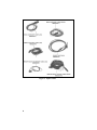
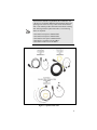
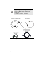
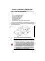
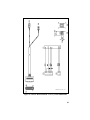
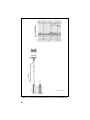
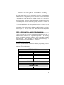
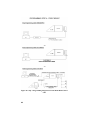
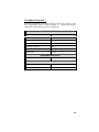
Installation Manual
LBI-38901T
Orion™
Mobile Radio
CREDIT
M/A-COM and EDACS are registered trademarks and Orion, ProGrammer, and ProVoice are
trademarks of M/A-COM, Inc.
TORX is a registered trademark of CAMCAR/TEXTRON.
POZIDRIV is a registered trademark of Phillips International Company.
IBM is a registered trademark of IBM.
Windows is a registered trademark of Microsoft Corporation.
Molex is a registered trademark of Molex Company.
All other brand and product names are trademarks, registered trademarks or service marks of their
respective holders.
This manual is published by M/A-COM, Inc., without any warranty. Improvements and changes to this
manual necessitated by typographical errors, inaccuracies of current information, or improvements to programs
and/or equipment, may be made by M/A-COM, Inc., at any time and without notice. Such changes will be
incorporated into new editions of this manual. No part of this manual may be reproduced or transmitted in any
form or by any means, electronic or mechanical, including photocopying and recording, for any purpose,
without the express written permission of M/A-COM, Inc.
Copyright© 1993-2004, M/A-COM, Inc. All rights reserved.
2
TABLE OF CONTENTS
Page
INTRODUCTION ............................................................................. 4
UNPACKING AND CHECKING EQUIPMENT ............................ 5
INSTALLATION (Single Control Unit) ......................................... 11
STEP 1 – PLAN THE INSTALLATION ................................ 11
STEP 2 - LOCATE TOOLS REQUIRED................................ 12
Vehicles Powered By Liquefied (Lp) Gas ........................ 12
STEP 3 – INSTALL CABLES................................................. 13
Power Cable ...................................................................... 13
Ignition Sense (All Applications)...................................... 14
Accessory Cable (Front Mount) ........................................ 16
Accessory and Control Cable (Remote Mount) ................ 24
STEP 4 – MOUNT CONTROL UNIT AND RADIO ............. 34
Control Unit Mounting (Remote Applications Only)........ 34
Pigtail Bracket ................................................................... 34
Radio Front Mount And Final Hook-Up........................... 37
Radio Remote Mount and Final Hook-Up ........................ 38
Cassette Mounting (EURO Only) ..................................... 40
STEP 5 - INSTALL OPTIONS AND ACCESSORIES........... 44
Speaker D2LS1F ............................................................... 44
Microphone Hanger and/or Hookswitch Mounting .......... 44
Siren and Light .................................................................. 45
INSTALLATION (Dual Control Units).......................................... 47
STEP 1 - PRE-INSTALLATION PROGRAMMING ............. 47
Front Mount Procedure ..................................................... 47
Remote Mount Procedure.................................................. 51
STEP 2 – INSTALL DUAL CONTROL UNITS .................... 55
Front Mount ...................................................................... 55
Remote Mount................................................................... 58
DUAL RADIO UNITS.................................................................... 63
STEP 1 - PRE-INSTALLATION PROGRAMMING ............. 63
Master Radio Programming .............................................. 64
Slave Radio Programming................................................. 64
STEP 2 – INSTALL CABLES/EQUIPMENT......................... 67
Front Mount ...................................................................... 67
Remote Mount................................................................... 69
Keyloading the Radio........................................................ 74
Keyloading a Dual Radio .................................................. 75
TECHNICAL ASSISTANCE ......................................................... 78
3
INTRODUCTION
This manual contains installation instructions for the Orion™ Mobile radio unit
and associated accessories. These instructions cover the mounting and
cabling of the radio. Interconnection and wiring diagrams are provided for
reference. Before the installation, program the radio using the following:
•
IBM® compatible personal computer
•
TQS3385 – ProGrammer™ PC Software
or
TQS3389 - Conventional ProGrammer PC Software
•
TQ3370 - Serial/Flash Programming Interface Module
(required with TQ3377 cable only)
•
One of the following programming cables:
*
o
TQ3377 (19B802554P15) – Shop Programming Cable (requires
TQ3370)
o
TQ3409 (CA101288V15) - Shop Programming Cable (does not
require TQ3370)
o
*TQ3410 (CA101287V1) - Field Programming Cable (does not
require TQ3370)
The field programming cable must be used with one of the following
accessory cables:
CA101288V2, CA101288V4, CA101288V10
ORION UHF MOBILES
CAUTION
4
The PC programmer automatically defaults the receiver
oscillator shift to position No. 2. When field programming,
the receive frequencies for Orion UHF mobiles, the oscillator
shift must be programmed to position No. 1 or No. 3. Enter
the CONVENTIONAL and/or TRUNKED FREQUENCY
SET screen of the PC programmer and set the values in the
“OS” column to “1” or “3”.
UNPACKING AND CHECKING EQUIPMENT
Carefully unpack the radio and identify each item in the shipping container as
listed below. The available options for the Orion Mobile Radio are covered in
Table 1. If damage has occurred to the equipment during shipment, file a
claim with the carrier immediately.
•
Orion Mobile radio unit
•
Microphone
D2MC3Z
•
Speaker
D2LS1H
•
Power Cable
or
Control Cable
D2CE1V
D2CF9A
D2CE1Y
•
Front Mount Bracket Kit or
Remote Mount Kit with
Control Unit Mount Kit
D2MA3N
D2MA3R
D2MA3J
•
Operator's Manual
LBI-38888
•
Installation Manual
LBI-38901
Figure 1: Orion Mobile Radio Components
USA
EURO
Figure 2: Rear View of Radios
5
Figure 3: Option Cables
6
At the time this manual was published, M/A-COM, Inc. was
in the process of offering additional programming cables and
replacing some of the accessory cables for the Orion mobile
radio. This manual provides information on both the existing
cable offerings and the replacement cables. The following
cables are impacted:
NOTE
CA101288V2 will replace 19B802554P2
CA101288V4 will replace 19B802554P4
CA101288V10 will replace 19B802554P10
CA101287V1, V2 and V3 will be added
CA101288V15 and V30 will be added
Figure 4: Option Cables con’t
7
NOTE
The programming cables shown in Figure 5 do not require the
TQ3370 interface box. The field programming cables shown
in Figure 5 are ONLY compatible with the following
accessory cables:
CA101288V2, CA101288V4, CA101288V10
Programming Interface Cable,
CA101287V1 and Mobile Data Interface,
CA101287V3
CA101287V2
Keyloading Interface
Figure 5: Programming/Interface Cables
8
Table 1: Orion Mobile Radio Options And Accessories
OPTION
DESCRIPTION
Z OPTIONS
D2ZN1A
Accessory Kit–Front Mount with Standard Option Cable
D2ZN1B
Accessory Kit–Front Mount with Extended Option Cable
D2ZN1C
Accessory Kit–Front Mount Euro with Standard Option Cable
D2ZN1D
Accessory Kit–Front Mount Euro with Extended Option Cable
D2ZN1F
Accessory Kit–Remote Mount with Standard Option Cable, 50W TX and below
D2ZN1G
Accessory Kit–Remote Mount with Standard Option Cable, 60W TX and above
D2ZN1H
Accessory Kit–Remote Mount with Extended Option Cable, 50W TX and below
D2ZN1J
Accessory Kit–Remote Mount with Extended Option Cable, 60W TX and above
D2ZN1K
Accessory Kit–Remote Mount with Standard Option Cable, Low Band
D2ZN1L
Accessory Kit–Remote Mount with Extended Option Cable, Low Band
D2ZN1M
Accessory Kit–Remote Mount Euro with Standard Option Cable
D2ZN1N
Accessory Kit–Remote Mount Euro with Extended Option Cable
D2ZN1P
Accessory Kit–Remote Mount Motorcycle with Extended Option Cable
D2ZN1R
Accessory Kit–Remote Mount Motorcycle with no Option Cable
D2ZN1S
Accessory Kit–Remote Mount Euro Motorcycle with Extended Option Cable
D2ZN1T
Accessory Kit–Remote Mount Euro Motorcycle with no Option Cable
D2ZN1U
Dual Control, Scan Control Unit
D2ZN1V
Dual Control, System Control Unit
D2ZN1W
Dual Radio (50 watt TX and below)
D2ZN1X
Dual Radio (60 watt TX and above)
D2ZN1Y
Motorcycle Conversion, Field Upgrade, Remote Mount Radio
D2ZN1Z
Motorcycle Conversion, Field Upgrade, Remote Mount Euro Radio
D2AN1E
Antenna, Low Band WB, 29.7-38 MHz
D2AN1F
Antenna, Low Band WB, 33-43 MHz
4 DIGIT OPTIONS
D2AN1G
Antenna, Low Band WB, 37-49 MHz
D2AN1L
Antenna, 800 MHz, ¼ Wave Whip
D2AN1M
Antenna, 900 MHz, ¼ Wave Whip
D2AN1R
Antenna, VHF/UHF, ¼ Wave Whip
D2CE1V
Power Cable, 7.5M (60W TX and above)
D2CE1W
Accessory Cable, Front Mount
D2CE1X
Accessory Cable, Remote Mount
D2CE1Y
Radio Control Cable, Remote Mount, 5.5M
D2CE1Z
Accessory Cable, Euro Front Mount
D2CE5R
Extended Option Accessory Cable, Front Mount
D2CE5S
Radio Control Cable, Extended Option, Remote Mount, 5.5M
D2CE5T
Extended Option Accessory Cable, Remote Mount
D2CE5U
Extended Option Accessory Cable, Euro Front Mount
9
OPTION
DESCRIPTION
D2CE5V
Radio Control Cable, Euro Remote Mount, 5.5M
D2CE5W
Radio Control Cable, Extended Option Euro Remote Mount, 5.5M
D2CE5Z
Dual Control Cable, Remote Mount, 9.0M
D2CE7A
Dual Radio Cable, Remote Mount, 2.0M
D2CF7B
Extended Option Accessory Cable, Motorcycle
D2CF7C
Radio Control Cable, Extended Option Remote Mount Motorcycle, 2.3M
D2CF7D
Radio Control Cable, Extended Option Euro Remote Mount Motorcycle, 2.3M
D2CF7E
Power Cable, Motorcycle, 1.0M
D2CF9A
Power Cable, 7.5M (50W TX and below)
D2CP5L
Scan Control Unit (4 BTN), Front Mount (including Label)
D2CP5M
System Control Unit (16 BTN), Front Mount (including Label)
D2CP5R
Scan Control Unit (4 BTN), Remote Mount (including Label)
D2CP5S
System Control Unit (16 BTN), Remote Mount (including Label)
D2LS1H
Speaker (4 OHM)
D2LS1U
Speaker (8 OHM, Parallel Audio Appl)
D2MA3J
Mounting Bracket Kit, Remote Mount Control Unit
D2MA3N
Mounting Bracket Kit, Front Mount Radio/Euro Remote Mount Radio
D2MA3R
Mounting Bracket Kit, Remote Mount Radio
D2MA5G
Mounting Bracket Kit, Motorcycle CU (Microphone Hanger included)
D2MA5H
Mounting Bracket Kit, Motorcycle Radio Case
D2MA5J
Mounting Bracket Adapter Kit, Motorcycle Radio Case
D2MC3Z
Microphone
D2MC5A
Desk Microphone
D2MC5L
Noise Canceling Microphone
D2MC5N
DTMF Microphone
D2MK3B
Radio Front (Remote Mount) (including Label)
D2MK3E
Keycap Kit, Scan Control Unit
D2MK3F
Keycap Kit, System Control Unit
D2MN1A
Microphone Hanger
D2PD1T
Filter, Power, Motorcycle Appl
1016
Siren and Light Control Module
1020
100W Speaker TS100
1021
100W Speaker BP100
TQ3409
Programming Cable, Shop (CA101288V5). Does not require TQ3370
TQ3410
Programming Cable, Field (CA101287V1). Does not require TQ3370
TQ3370
Programming Interface Module Kit 110 VAC, only needed for 19B802554P15
TQ3370220
Programming Interface Module Kit 220 VAC, only needed for 19B802554P15
TQ3377
Programming Cable for Orion (19B802554P15). Requires TQ3370
TQ3385
ProVoice /EDACS Windows Radio ProGrammer Only
TQ3389
Conventional Windows Radio ProGrammer Only
RADIO PROGRAMMING OPTIONS
10
™
®
®
INSTALLATION (SINGLE CONTROL UNIT)
STEP 1 – PLAN THE INSTALLATION
Figure 6 provides an example of a typical mobile radio (remote mount)
installation. Before starting, plan the radio installation carefully so that it will
be:
• safe for the operator and passengers
• away from airbag deployment area
• convenient for the operator to use
• protected from water damage
• neat and easy to service
• safe and out of the way for passengers and auto mechanics
M/A-COM, Inc. recommends the radio be installed by one of the many M/ACOM, Inc. Authorized Service Centers located throughout the United States.
Experienced service centers can provide a proper radio installation and make
any required final adjustments.
Figure 6: Typical Installation (Remote Mount Shown)
•
Vehicular Electronics- fuel injection systems, anti-skid
braking systems, cruise control systems, etc., are typical of
the types of electronic devices which may be prone to
malfunction due to the lack of protection from radio
frequency energy present when a radio is transmitting. If the
vehicle contains such equipment, consult dealer to determine
if such electronic equipment will perform normally when the
radio is transmitting.
•
For passenger safety, mount the radio securely so the unit
will not break loose in the event of a collision.
WARNING
11
STEP 2 - LOCATE TOOLS REQUIRED
The equipment required for installing the Orion Mobile Radio is listed below:
•
Crimping tool for fuse holder
•
Electric drill for drilling mounting holes
•
Drills and circle cutters as follows:
No. 31 (1/8”) drill
No. 27 (9/64”) drill
5/8” drill or circle cutter
3/4” circle cutter, hole saw or socket punch
•
Phillips and flat-blade screwdrivers
•
POZIDRIV® driver
•
No. 20 TORX® driver
CAUTION
Be careful to avoid damaging vital part (fuel tank,
transmission housing, etc.) of the vehicle when drilling
mounting holes. Always check to see how far the mounting
screws will extend below the mounting surface before
installing.
If pilot holes must be drilled, remove all metal shavings from
drilling holes before installing screws.
Vehicles Powered By Liquefied (Lp) Gas
Radio installation in vehicles powered by liquefied petroleum gas, where
the LP gas container is located in the trunk or other sealed-off space
within the interior of the vehicle, must conform to the National Fire
Protection Association Standard NFPA 58. This requires that:
•
The space containing radio equipment be isolated by a seal from the
space containing the LP gas container and its fittings.
•
Outside filling connections be used for the LP gas container.
•
The LP gas container space be vented to the outside of the vehicle.
12
STEP 3 – INSTALL CABLES
To ensure the feasibility of the planned cable routings, it is recommended that
the cables be run before mounting the radio. The radio can be installed as a
Front Mount, Remote Mount or Cassette Mount. The type of mount, the
application, and the options to be installed should be considered when
planning the cable runs. The following figures should be referenced
throughout the installation:
•
•
•
•
Front Mount Installation Diagram - Figure 8 thru Figure 12
Front Mount Cable Diagrams - Figure 13 thru Figure 17
Remote Mount Installation Diagrams – Figure 18 thru Figure 24
Remote Mount Cable Diagrams – Figure 25 thru Figure 29
Be sure to leave some slack in each cable going to the radio, so the radio can
be pulled out for servicing with the power applied and antenna attached. Coil
any surplus cables and secure them out of the way. Try to route the cables
away from locations where they will be exposed to heat (exhaust pipes,
mufflers, tailpipes, etc.), battery acid, sharp edges or mechanical damage or
where they will be a nuisance to automobile mechanics, the driver, or
passengers. In order to prevent interference, keep wiring away from
electronic computer modules, other electronic modules, and ignition circuits.
In addition, try to utilize existing holes in the firewall, trunk wall, and the
channels above or beneath doors. Channels through door and window
columns, convenient for running cables, can also be used unless rigid or
flexible conduit is to be installed for cable runs.
Power Cable
The USA power cable (19B802622P1 or P3) consists of a red lead (A+) and a
black lead (A-) connected to a molded 2-pin power connector and supplied
with ring terminals. The EURO power cable also consists of a red lead (A+) a
black lead (A-) terminated with ring terminals, but it is connected to P1 of the
accessory cable or P1 of the control cable (in remote applications).
To install the power cable:
1.
Drill a 5/8” hole in the firewall for the cable run and insert the rubber
grommet. Run the cable through this grommet to the battery location.
Secure the cable at several locations within the engine compartment to
prevent possible damage to cable.
2.
Strip back the insulation approximately 3/8″ from the end of the black
lead. Slide one of the large heat shrink sleeves onto the wire and crimp a
battery ring terminal onto this lead. Heat shrink the sleeve over the crimp
connection. Connect the black lead directly to the battery negative (-) or
ground frame member.
13
3.
Cut off 12-18″ from the red lead. Strip back the insulation approximately
3/8″ on each end of the wires. Insert the wire ends into the small
openings at the end of each fuse holder section and crimp a fuse
connector to each wire. Prepare the other end of the short wire in the
same manner as in (2) and connect to the positive (+) terminal of the
battery.
NOTE
•
Do not install fuse into fuse holder until installation is
completed and all connections have been checked.
•
USA Power Cable 19B802622P3 is used only with radio
with 50 watts or less RF power output.
Figure 7: Power Cable 19B802622P1 or P3 (USA Only)
Ignition Sense (All Applications)
The fuse holder must be attached to the yellow sense lead along with the ring
terminal as follows:
1.
Cut the yellow sense lead approximately 6-12" from the end to be
connected to the power source.
2.
Strip the insulation from each end of the short lead and from the end of
the long lead by at least 3/8".
3.
Insert the stripped end of the long lead and one end of the short lead into
the narrow end of each fuse holder half.
4.
Crimp the leads in the fuse holder halves with a crimping tool.
5.
Insert the 3 amp fuse into one end of the fuse holder and join the two fuse
holder halves firmly together.
6.
Attach the ring terminal to the end of the short lead and connect this lead
to the ignition "ON" sense point. (Preferably to an "Accessory" point in
the vehicle fuse panel that is switched on when the vehicle ignition
switch is in the ACCESSORY and RUN positions.)
14
NOTE
CAUTION
•
The radio, as shipped from the factory, has the
"ignition sense" feature disabled. As such, the radio
is powered ON or OFF as determined by the front
panel ON/OFF/ VOLUME control only (assuming
A+ and A- are connected). To enable "ignition
sense" feature, open top cover of radio and remove
shield from logic PWB. Slide switch SW601 from
position 3-2 to 1-2. Replace shield and top cover.
Be sure to apply correct torque to screws holding top
cover in place. See Maintenance Manual.
•
The "Accessory" point should drop to ZERO volts
when the engine is cranked and return to +12 volts
after the engine is started. If a point is chosen that
drops to a voltage between zero and +12 volts, the
radio may execute a power-up cycle several times
during start up. It is recommended that the terminal
be measured with a voltmeter to ensure it shuts off
(goes to zero volts) during engine cranking.
Certain problems may be encountered when accessory
equipment is connected to the ignition or accessory lines of
the vehicle, where these lines may have large filter capacitors
and a leakage path present. If the radio does not turn off
within a reasonable amount of time after the ignition is turned
off, first try a different accessory or ignition sense pick up
point in the vehicle. Many vehicles have more than one
circuit that is switched by the ignition switch, and one may be
available that does not have large filter capacitors or a leakage
path present.
If a different pickup point cannot be found, add a 470-ohm, 1watt resistor from the ignition sense pick point to ground.
This will discharge the capacitor(s) or reduce the leakage
voltage to a low value. Current drain through this resistor
will be minimal (less than 0.03A) when the ignition is
switched on.
15
Accessory Cable (Front Mount)
The basic accessory cable consists, at one end, the basic accessories connector
(P3), the speaker connector (P2), and the ignition sense lead. At the other
end, plug P1 connects to the Option/Remote Control connector (ORCC),
which is mounted on the back of the radio. The EURO accessory cable
contains the red and black leads of the power cable.
The Extended Option accessory cable is the same as the basic accessory cable,
but has an Extended Option plug (P4). The CA101288V2 Extended Option
Accessory Cable has a pigtail (P5) at P1 that provides easy access to the front
of the radio for programming, keyloading, and mobile data.
NOTE
The EURO ORCC is the opposite gender from the USA
ORCC. Interconnect diagrams for each of these cables are
provided on pages 19-23.
The following cables are available for Front Mount applications:
•
•
•
•
•
19B802554P1
19B802554P11
19B802554P2
CA101288V2
19B802554P12
- Basic Accessory Cable (USA Models)
- Basic Accessory Cable (EURO Models)
- Extended Option Accessory Cable (USA Models)
- Extended Option Accessory Cable (USA Models)
- Extended Option Accessory Cable (EURO Models)
Figure 8: Front Mount Basic Accessory Interconnections
(USA Models Only)
16
Figure 9: Front Mount Basic Accessory Interconnections
(EURO Models Only)
Figure 10: Front Mount Extended Option Accessory Interconnections
using 19B802554P2 (USA Models Only)
17
*(P5) Provides access for Programming/ Keyloading/ Mobile Data
Figure 11: Front Mount Extended Option Accessory Interconnections
using CA101288V2 (USA Models Only)
Figure 12: Front Mount Extended Option Accessory Interconnections
(EURO Models Only)
18
(19B802554, Sh.1, Rev. 23)
Figure 13: USA Front Mount Standard Accessory Cable 19B802554P1
19
(19B802554, Sh.9, Rev. 23)
Figure 14: EURO Front Mount Standard Accessory Cable
19B802554P11
20
(19B802554, Sh.2, Rev. 23)
Figure 15: USA Front Mount Extended Option Accessory Cable
19B802554P2
21
Figure 16: Front Mount Extended Option Accessory Cable CA101288V2
22
(19B802554, Sh.10, Rev. 23)
Figure 17: EURO Front Mount Extended Option Accessory Cable
19B802554P12
23
Accessory and Control Cable (Remote Mount)
The control cable connects the Control Unit (through the R1A) to the Radio
Transceiver in remote applications. Plug P2, at one end, connects to the
Remote Control Cable connector (RCCC) mounted on the back of the R1A.
The Ignition Sense wire is also part of P2. The other end of the control cable
(P1) connects to the ORCC mounted on the back of the radio. P1 of the
EURO control cable contains the power cable leads.
The CA101288V4 Extended Option Control Cable has a pigtail (P5) at P2
that provides easy access to the front of the remote control unit for
programming, key loading and mobile data. The Extended Option accessory
cable is the same as the basic accessory cable, but has an Extended Option
plug (P4).
NOTE
The EURO ORCC is the opposite gender from the USA
ORCC. Interconnect diagrams for each of these cables are
provided on pages 27 - 33.
The following cable combinations are available for Remote Mount
applications:
•
19B802554P6 - Basic Accessory Cable (USA Models)
19B802554P3 - Remote Control Cable (USA Models)
•
19B802554P6 - Basic Accessory Cable (EURO Models)
19B802554P13 - Remote Control Cable (EURO Models)
•
19B802554P7 - Extended Option Accessory Cable
19B802554P4 - Remote Control Extended Option (USA Models)
•
19B802554P7 - Extended Option Accessory Cable
CA101288V4 - Remote Control Extended Option (USA Models)
•
19B802554P7 - Extended Option Accessory Cable
19B802554P14 - Remote Control Extended Option (EURO Models)
24
Figure 18: Remote Mount Basic Accessory Interconnections
(USA Models Only)
Figure 19: Remote Mount Basic Accessory Interconnections
(EURO Models Only)
Figure 20: Remote Mount Extended Option Accessory Interconnections
(USA Models Only)
25
*(P5) Provides access for
Programming/Keyloading/Mobile Data
Figure 21: Remote Mount Extended Option Accessory Interconnections
using CA101288V4 (USA Models Only)
Figure 22: Remote Mount Extended Option Accessory Interconnections
(EURO Models Only)
26
(19B802554, Sh.5, Rev. 23)
Figure 23: Remote Mount Standard Accessory Cable 19B802554P6
27
(19B802554, Sh.6, Rev. 23)
Figure 24: Remote Mount Extended Option Accessory Cable
19B802554P7
28
(19B802554, Sh.3, Rev. 23)
Figure 25: USA Remote Control Cable 19B802554P3
29
(19B802554, Sh.4, Rev. 23)
Figure 26: USA Remote Extended Option Control Cable 19B802554P4
30
Figure 27: Remote Extended Option Control Cable CA101288V4
31
(19B802554, Sh.11, Rev. 23)
Figure 28: EURO Extended Options Remote Control Cable
19B802554P13
32
(19B802554, Sh.12, Rev. 23)
Figure 29: EURO Extended Options Remote Control Cable
19B802554P14
33
STEP 4 – MOUNT CONTROL UNIT AND RADIO
Control Unit Mounting (Remote Applications Only)
1.
Use the bracket as a template and mark and drill the mounting holes. Be
sure to leave enough room at the rear of the control unit for the cable
connector. Refer to Figure 30 for control unit mounting bracket
installation.
2.
Secure the mounting bracket using the four No. 10 x 3/4 self-tapping
screws supplied. (Use No. 10 x 1 ½ if needed.)
3.
Secure the control unit to the bracket with the two 1/4-20 x 5/8 hex head
screws and lock washers provided.
Top Mount
Bottom Mount
Figure 30: Control Unit Mounting Brackets
Pigtail Bracket
The Pigtail Bracket mounts the DB15 connector for easier user access. The
DB15 connector facilitates radio programming and keyloading by the
customer without the need to dismantle the radio or Control Unit. There are
two Pigtail brackets, one for use with the Control Unit and one for use with
the radio-mounting bracket. This section includes procedures to mount the
Pigtail Brackets in each of these configurations.
Control Unit Mounting
For Control Unit mounting, attach the pigtail bracket to the side of the Control
Unit bracket using existing mounting bracket hardware. The Pigtail Bracket
can be mounted to the left or right side of the Control Unit. Hardware Kit,
KT101533V6, contains Pigtail mounting bracket and hardware required to
attach Pigtail to bracket.
34
NOTE
When mounting two DB-15 connectors to the control unit,
mount one pigtail bracket on each side of the existing
mounting hardware of the control unit.
1.
Attach DB15 connector to the rectangular end of bracket with 2 pan head
machine screws and washers. See Figure 31.
2.
Remove the ¼-20 x 5/8 hex head screw and washer from the side of the
Control Unit bracket where the Pigtail installation is desired. Retain the
hardware for Step 4.
3.
Align the single hole at the end of the Pigtail Bracket with the holes in the
Control Unit bracket and the Control Unit.
4.
Replace washer and insert hex head screw and tighten. See Figure 31.
Figure 31: DB15 connector mounted on Control Unit Pigtail Bracket and
Pigtail Bracket installed on Control Unit
CONTROL UNIT WITH
BRACKET FOR PIGTAIL
Figure 32: Control Unit with Bracket for Pigtail
35
Radio Bracket Mounting
For Radio Bracket mounting, the Pigtail Bracket is attached to either side of
the Radio mounting bracket. Hardware Kit, KT101533V5, contains the
Pigtail
Bracket hardware to attach the Pigtail to the bracket.
1.
Remove the plastic spacer/glide from the left or right side of the Orion
transceiver mounting bracket. This will get reapplied to the other side of
bracket where it is currently installed.
2.
Slide the Orion into the transceiver bracket.
3.
Slide the pigtail mounting bracket between the Orion radio casting and
the transceiver bracket (right or left).
4.
Place the plastic spacer/glide you removed in step #1 back on the
transceiver bracket.
5.
Re-use the Orion mounting hardware to fasten the Pigtail Bracket to the
side of the Orion. Make sure you use a flat washer under each screw (See
Figure 33).
6.
Before tightening Pigtail Bracket down, position the bracket up or down
to suit the installation requirements. Then tighten down all screws using
the proper torque specifications.
Figure 33 – Pigtail Bracket Mounted on Radio
36
Radio Front Mount And Final Hook-Up
Typically, the bracket shown in Figure 34 is used for Front Mount
applications. The bracket can be mounted so that it is either above or below
the radio as convenient. The bracket shown in Figure 30 can also be used for
Remote Mount applications but is not recommended for 110 watt VHF
radios or 100 watt UHF radios. The following instructions are for a Front
Mount installation using the bracket shown in Figure 34.
1.
Using the bracket as a template, mark and drill the mounting holes using
a No. 27 drill. Be sure to leave enough room at the front and rear of the
radio for cable connections.
2.
Mount bracket using four 1/4"-14 x 3/4" sheet metal screws. (Use 1/4"14 x 1-1/2" screws if needed.)
3.
Place radio into mounting bracket and secure using four M4 x 10 mm hex
head screws, M4 flat washers and M4 lock washers (supplied) using the
No. 20 Torx Driver.
4.
Connect antenna coaxial cable to antenna connector (TNC).
5.
Connect front mount accessory cable connector P1 to the Option/Remote
Control Connector (ORCC) and secure with the two captive screws in the
connector to the radio.
6.
Connect front mount accessory cable connector P2 to speaker cable
connector.
7.
Connect power cable to power connector on rear of radio unit and secure
with the two captive screws to the radio unit.
8.
Connect microphone connector to connector on front panel and secure
with captive screw.
NOTE
9.
Do not torque microphone connector screw greater than 2 inlb. Alternatively, finger tight plus ¼ turn is acceptable.
If there are no other accessory connections, tie back plug P3 to main
cable.
10. Recheck all connections before inserting fuse into transmit fuse assembly.
37
Top Mount
Bottom Mount
Figure 34: Mounting Bracket Installation
Radio Remote Mount and Final Hook-Up
The bracket shown in Figure 35 is used for Remote Mounting (USA only). In
some applications, the bracket shown in Figure 34 can also be used. The
following instructions are for a Remote Mount installation using the bracket
shown in Figure 35.
1.
Using the bracket as a template, mark and drill the mounting holes using
a No. 27 drill. Be sure to leave enough room at the rear of the radio unit
for the cable connections.
2.
Mount bracket using four 1/4"-14 x 3/4" sheet metal screws. (Use 1/4"14 x 1" if needed.) The bracket can be mounted so that it is either above
or below the radio as convenient.
3.
Slide the radio unit into the bracket by aligning bracket guides with
grooves on each side of radio (rear of radio should be inserted first).
Slide radio back until screw holes in front of bracket align with screw
holes in side of radio. See Figure 35.
4.
Secure radio to the bracket with two M4 x 10 mm socket head screws
provided.
5.
Connect antenna coaxial cable to antenna connector (TNC).
6.
Connect remote control cable connector P1 to the ORCC connector on
the radio unit and secure with the two captive screws.
38
7.
Connect other end of the remote control cable to the remote control cable
connector (RCCC) on the remote control unit.
8.
Connect remote mount accessory cable connector P1 to the option
connector (OPT) on control unit. Then, connect the speaker to connector
P2 and accessory connector P3 to any options (hookswitch, etc.). If
connector P3 is not used, insulate and tie back to main cable.
9.
Recheck all connections and cables before inserting fuse into transmit
fuse assembly.
Top Mount
Bottom Mount
Figure 35: Remote Mounting Bracket Installation (USA Only)
39
Cassette Mounting (EURO Only)
The cassette mounting assembly is designed to mount in a standard DIN space
in the instrument panel or console. This mounting permits rapid insertion and
removal of the radio unit from the vehicle. All connections are made through
a quick disconnect connector at the rear of the cassette mounting assembly to
the radio unit. This connector is part of the cassette assembly. The cassette
assembly is shown in Figure 36.
Figure 36: Cassette Assembly (EURO Only)
Cassette Assembly Mounting
1.
Insert the cassette assembly in the mounting location. Secure the cables
with the sheet metal screws and retaining straps provided.
2.
Secure the back of the cassette assembly using the mounting stud (located
at the back of the cassette assembly), No. 6 flat washer, No. 6 split lock
washer and No. 6 wing nut.
3.
Several tabs are located on the top, bottom and sides of the cassette
assembly. These tabs are conveniently located near the front of the
assembly and can be bent out as needed to further secure the cassette
assembly to the vehicle.
4.
Next, install the handle assembly:
a.
40
Turn the radio upside down. Remove the two small machine screws
on the bottom of the radio, near the front. Use upward pressure on
screws to engage captivated threads for removal.
b.
Using the machine screws and flat washers provided with the handle
assembly, attach the handle to the bottom of the radio. The two holes
on the handle should align with the two holes on the radio created by
step (A). Once installed, the rubber handle should rotate freely from
over top of the radio to just out in front of the control unit
(approximately 90 degrees). Be sure to torque the two mounting
screws within 6.5 to 8.25 in/lb limits.
5.
Connect the antenna coaxial cable to the cassette mounting assembly rear
connector.
6.
Connect the power leads and the ignition sense leads as described in
previous sections. See Figure 38.
7.
Connect the speaker cable connector P2 to the speaker and the basic
accessory connector P3 to the following options (if used, see Figure 38.)
OPTION
Ext. Hookswitch
PLUG AND PIN
P3-3 (HOT)
P3-6 (GND)
Foot Switch
P3-5 (HOT)
Horn Relay
P3-1 (HOT)
P3-2 (GND)
P3-4 (GND)
8.
Connect the extended option accessory plug P4 to the following options
(if used, see Figure 36.)
•
Mobile Data Terminal
•
Public Address (External Amplifier)
•
External Microphone
•
External Tone Encoder
•
External Tone Decoder
•
Output (User Defined)
•
Input (User Defined)
CAUTION
Refer to accessory manual supplement for details regarding
the extended options listed above. DO NOT CONNECT
DIRECTLY TO A PC OR DATA TERMINAL. DAMAGE
COULD RESULT!
41
9.
With the handle assembly in the UNLOCKED position (out in front of
the control unit), insert the radio into the cassette assembly. Slide the
radio into the cassette assembly until the back of the radio meets the back
of the cassette assembly.
NOTE
Caution should be used while engaging the radio in the
cassette the first few times until the cabling in the cassette
mount assembly has settled into its permanent location. To
insure proper first time engagement, the following procedure
should be followed:
Insert radio into cassette mount opening and slide in until
some spring resistance is felt. Holding the handle, move the
radio gently from side to side until the unit locates the
necessary connectors. Engage the radio handle in the sheet
metal hooks, which protrude from the lower corners of the
cassette mount casing. Rotate the handle upward to fully
engage the radio. See Figure 37. DO NOT FORCE THE
CONNECTOR ENGAGEMENT.
If the radio does not engage using the above method, a large
flat blade screwdriver may be used to slightly re-position the
37-pin connector.
10. Recheck all connections and cables before inserting fuse into transmit
fuse assembly.
Figure 37: Handle Assembly in LOCKED Position
42
(19C852366, Sh.2, Rev.2)
Figure 38: Cassette Assembly Schematic Diagram
43
STEP 5 - INSTALL OPTIONS AND ACCESSORIES
Speaker D2LS1F
The speaker kit includes the speaker, mounting bracket and connecting cable.
Mount the speaker so it is directed to the operator but does not present a
hazard in the event of an accident. The speaker can be mounted on the lower
edge of the instrument panel, the firewall or above the windshield in some
trucks.
1.
Use the mounting bracket as a template for locating the mounting holes
and mount the speaker as shown in Figure 39.
2.
To connect the speaker to the accessory cable, refer to the applicable
installation procedures.
Microphone Hanger and/or Hookswitch Mounting
The microphone hanger, or hookswitch, should be mounted in a location
convenient to the operator where it will not interfere with the safe operation of
the vehicle or pose a hazard to vehicle passengers. The hanger or hookswitch
is designed to be mounted with the open end of the mounting button slot
pointed upward. Use the hanger or hookswitch as a template to mark and drill
the mounting holes. Mount with the self-tapping screws provided.
Figure 39: Speaker Mounting Bracket
44
Siren and Light
For instructions about installing the Federal Signal Corporation Siren and
Light Kit, refer to the Federal Signal Corporation Installation Instructions
(Federal Systems part number 255287B, rev. B or higher).
Program the radio to work with the Federal Systems Siren and Light Kit,
using the instructions outlined in the ProGrammer On-Line Help under “Siren
and Light Options.”
The following issues have been reported on some Orion
Siren/Light installations using the Federal Signal Corporation
Siren and Light Kit:
•
Occasional false activation of Siren and Light functions
when the ignition is turned to the “on” position and/or
when the vehicle is started.
•
Occasional failure to enable Siren or Light functions via
control head, which can be temporarily resolved by either
power cycling the radio or turning the car ignition “off”
and then “on” again.
•
Occasional re-activation of Siren and Light function after
siren module has been turned off
NOTE
To resolve the first two issues, modify the Federal Systems control cable
as follows:
1.
Remove the outer shell from the DB25 side of the Federal Systems
control cable.
2.
Add a jumper from pin 1 to pin 19.
This modification to the SS2000 cable harness will disable the Orion’s
capability to turn on and off the SS2000 from the front of the control head.
The SS2000 will now be turned on and off strictly by its own ignition switch
trigger line. (Red wire from 12 pin Molex® connector on SS2000 siren box.)
Follow the SS2000 Federal Signal installation instructions to attach the red
ignition line correctly.
45
To resolve false activation, refer to TSM Vol. 25, #2 problem/solution
below:
Problem:
Siren/Light functions change or turn off when switching
between radios in Dual Radio installations with a SS2000 siren
box.
Solution:
Keyboard maps and Siren/Light configuration must be identical
in both radio personalities to prevent this.
Additionally, in a Remote Mount Installation, there are three jumpers that
must be reconfigured in the Orion Remote control Unit for Siren/Light
operation. These jumpers are located on the Remote Interface Adapter (RIA),
a PC board in the back half of the unit. To access these jumpers, the RIA
must be removed from the control unit, as follows:
1.
Disassemble the Orion control unit using steps given in LBI-38909, page
4, “Disassembly Procedures”.
2.
Flex circuit PC2 does not need to be disengaged from J2, providing care
is taken to avoid excessive bending.
3.
Reconfigure jumper “AB” from center to “B”, jumper “CD” from center
to “D”, and jumper “EF” from center to “F”.
4.
Carefully reassemble RIA to the front control panel making sure that
there is adequate alignment and lubricant for the black O-ring gasket at
the mechanical interface between the RIA and the control panel. This
maintains the moisture seal of the control panel. Refer to LBI-38909,
figure 1B.
46
INSTALLATION (DUAL CONTROL UNITS)
The Dual Control feature can be configured for either front or remote mount
radio units. Each configuration provides for a Main Control Unit and an
Auxiliary Control Unit. In front mount configurations, the Main Control Unit
is mounted to the radio unit and the Auxiliary Control Unit is located in a
convenient location. In remote mount configurations, the Main Control Unit
is mounted separate from the radio unit, typically located in the vehicle cab
and the Auxiliary Control Unit located in a convenient location.
It is recommended that the units be programmed at a Service Center first, and
then transferred to the user's installation. However, some installation and
programming cables are designed to facilitate field programming, see Figure
40 thru Figure 43. All radio units in the Dual Control Unit configuration
MUST BE PROGRAMMED PRIOR to final installation.
STEP 1 - PRE-INSTALLATION PROGRAMMING
In order to provide each control unit with the proper identification code, the
radio and control units must be programmed sequentially. The following
sections provide the personality parameters settings required for installing
dual control units. These parameters are defined in the personality by the
radio programming software (ProGrammer - TQS3385).
Front Mount Procedure 1
Setup the Front Mount radio with one of the three programming cables as
shown in Figure 40. Program the radio and main control unit with the
following control configurations:
NETWORK OPTIONS
Dual Control
Audio Mode
Switching Mode
Siren Light Controller
Siren Light Connection
Speaker
Multiple Radio
Enable
Active
Independent
Unit A
Unit A
Disable
Disable
PROGRAM RADIO SETUP
Mobile Options
Push Button
ORION OPTIONS
Write Orion System Keypad File
Write Scan Keypad File
Enable (System control unit)
Enable (Scan control unit)
47
Figure 40: Step A Programming Diagram for Front Mount Dual Control
Unit
48
Front Mount Procedure 2
Setup the Front Mount radio and the Auxiliary Control Unit with one of the
three programming cables as shown in Figure 41. Program the auxiliary
control unit with the following control configurations:
NETWORK OPTIONS
Dual Control
Enable
Audio Mode
Active
Switching Mode
Independent
Siren Light Controller
Unit A
Siren Light Connection
Unit A
Speaker
Disable
Multiple Radio
Disable
PROGRAM RADIO SETUP
Mobile Options
Push Button
ORION OPTIONS
Write Orion System Keypad File
Enable (System control unit)
Write Scan Keypad File
Enable (Scan control unit)
49
Figure 41: Step B Programming Diagram Front Mount Dual Control
50
Remote Mount Procedure 1
Setup the remote mount radio and the main control unit with one of the three
programming cables as shown in Figure 42. Program the radio and main
control unit with the following control configurations:
NETWORK OPTIONS
Dual Control
Enable
Audio Mode
Active
Switching Mode
Independent
Siren Light Controller
Unit A
Siren Light Connection
Unit A
Speaker
Disable
Multiple Radio
Disable
PROGRAM RADIO SETUP
Mobile Options
Push Button
ORION OPTIONS
Write Orion System Keypad File
Enable (System control unit
Write Scan Keypad File
Enable (Scan control unit)
51
Figure 42: Step A Programming Diagram Remote Mount Dual Control
52
Remote Mount Procedure 2
Setup the Remote Mount radio and the Auxiliary Control Unit with one of the
three programming cables as shown in Figure 43. Program the auxiliary
control unit with the following control configurations:
NETWORK OPTIONS
Dual Control
Enable
Audio Mode
Active
Switching Mode
Independent
Siren Light Controller
Unit A
Siren Light Connection
Unit A
Speaker
Disable
Multiple Radio
Disable
PROGRAM RADIO SETUP
Mobile Options
Push Button
ORION OPTIONS
Write Orion System Keypad File
Enable (System control unit)
Write Scan Keypad File
Enable (Scan control unit)
53
Figure 43: Step B Programming Diagram Remote Mount Dual Control
54
STEP 2 – INSTALL DUAL CONTROL UNITS
Front Mount
The Dual Control Unit feature is configured such that only one Control Unit
can be used for Extended Option accessories. Connect all Extended Option
accessories through the Main Control Unit.
1.
Referring to Figure 44 and Figure 45, run the Dual Control Cable
(19B802554P9) between locations for the Radio Unit and Auxiliary
Control Unit. Be sure to locate the P2/P3 connector assembly at the radio
unit.
2.
After installing radio unit mounting hardware in the normal fashion,
connect the Dual Control Cable connector (P3) to the radio unit. Tighten
the two jackscrews on P3. Next, connect the Accessory cable
(19B802554P1, 19B802554P2, or CA101288V2) connector (P1) to the
Dual Control Cable connector (P2), and tighten the jackscrews on P2.
Connect the power cable, and install radio unit in mounting bracket.
3.
After installing the Auxiliary Control Unit in the normal fashion, connect
the Dual Control Cable (P1) to Auxiliary Control Unit, and tighten
jackscrews.
4.
Connect the Remote Mount Accessory cable (19B802554P6) to the
Auxiliary Control Unit.
5.
A yellow Ignition Sense lead is provided on the Dual Control Cable and
the Front Mount Accessory cable. If the “Ignition Sense” feature is
enabled on the radio unit, it is necessary to connect only one of the
yellow leads provided, whichever is convenient. Tape back the unused
yellow lead. (See page 14 for details.)
6.
Install the Speakers in convenient locations near each radio unit.
Parallel Audio Installation Requirements
NOTE
In special configurations that require both speakers to operate at
the same time (simultaneous audio), install the speakers for
parallel audio operation. For wiring information, refer to the
Parallel Audio Setup Insert section of Figure 44 and Figure 45.
Perform the following steps to install parallel audio speakers:
1. Use the two 8Ω speakers, part number 19A149590P12, in
place of the two 4Ω speakers, part number LS 102824V1.
2. Hardwire each speaker directly (without relays) as shown
in Figure 44 and Figure 45.
It is very important to use the correct speakers for this
application. Wiring 4Ω speakers in this configuration may cause
damage to the radio.
55
7.
Install a relay (19A149299P1) from the kits supplied at a location near
the leads from each speaker. For mounting, use the #8 x 3/4” sheet metal
screw and nut plate supplied with each kit.
8.
At a convenient point, cut one of the wires in each of the 2-wire speaker
cables, spread the leads, and strip the ends. Crimp a ¼” tab receptacle to
each end.
9.
Radio Unit Speaker: Connect the lead nearest the speaker to Pin 87A of
the relay. Connect the lead nearest the connector to Pin 30 of the relay.
Connect the speakers connector to the Accessory cables P2. See Figures
47 and 48.
10. Auxiliary Control Unit Speaker: Connect the lead nearest the speaker to
Pin 87 of the relay. Connect the lead nearest the connector to Pin 30 of
the relay. Connect the speakers connector to the Accessory cables P2.
See Figure 44 and Figure 45.
11. For each relay: Connect a #18 AWG black wire between the relay, Pin 85
and Accessory cable P3-1 (labeled “OUT2” on the schematic diagrams
in the service manual). Use a ¼” tab receptacle on the relay side and
mating Molex connector and pins on the accessory cable side. Connect
the mating Molex connector to the Accessory cables P3 when finished.
See Figure 44 and Figure 45.
12. For each relay: Connect a #18 AWG red wire to the relay, Pin 86. Cut to
length, and connect to the 1 amp fuse holder supplied. Use crimp on
connectors supplied. Connect the other side of the 1 amp fuse holder to
A+ battery source or vehicle A+ fuse block. Use #18 AWG red wire and
ring lug supplied, if needed. See Figure 44 and Figure 45.
13. Check the dual control operation using the operator’s manual as a test
guide. In the PC programming software, make sure the “DUAL
CONTROL SPEAKER” is programmed to “ACTIVE LOW”.
56
Figure 44: Dual Control Unit Front Mount Installation Configuration
using 19B802554P1 or P2
57
Figure 45: Dual Control Unit Front Mount Installation Configuration
using CA101288V2
Remote Mount
1.
Referring to Figure 46 and Figure 47, run the Remote Control Cable
(19B802554P3, 19B802554P4 or CA101288V4) between locations for
the Radio unit and Main Control unit.
2.
Run the Dual Control Cable (19B802554P9) between locations for the
radio unit and Auxiliary Control unit. Be sure to locate the P2/P3
connector assembly at the radio unit.
3.
After installing the radio unit in the normal fashion, connect the dual
control cable connector (P3) to the radio unit. Tighten the two
jackscrews on P3. Next, connect the Remote Control Cable connector
(P1) to the Dual Control Cable connector (P2), and tighten jackscrews on
(P2).
4.
After installing the Main Control Unit in the normal fashion, connect the
Remote Control Cable (P2) to the Main Control Unit and tighten
jackscrews.
58
5.
After installing the Auxiliary Control Unit in the normal fashion, connect
the Dual Control Cable (P1) to the Auxiliary Control Unit and tighten the
jackscrews.
6.
Connect the accessory cable (19B802554P6) to the Auxiliary Control
Unit. Connect either the accessory cable (19B802554P6) or the extended
option accessory cable (19B802554P7) to the Main Control Unit as
appropriate.
7.
A yellow ignition sense lead is provided on each control cable. If the
“Ignition Sense” feature is enabled on the radio unit, it is necessary to
connect only one of the yellow leads provided, whichever is convenient.
Tape back the unused yellow lead. See page 24 for details.
8.
Install the speakers in convenient locations near each control unit.
Parallel Audio Installation Requirements
NOTE
9.
In special configurations that require both speakers to operate
at the same time (simultaneous audio), install the speakers for
parallel audio operation.
For wiring information, refer to the Parallel Audio Setup
Insert section of Figure 46 and Figure 47. Perform the
following steps to install parallel audio speakers:
1. Use the two 8Ω speakers, part number 19A149590P12,
in place of the two 4Ω speakers, part number LS
102824V1.
2. Hardwire each speaker directly (without relays) as shown
in Figure 46 and Figure 47.
It is very important to use the correct speakers for this
application. Wiring 4Ω speakers in this configuration may
cause damage to the radio.
Install a relay (19A149299P1) from the kits supplied at a location near
the leads from each speaker. Use the #8 x 3/4” sheet metal screw and nut
plate supplied with each kit for mounting.
10. At a convenient point, cut one of the wires in each of the 2-wire speaker
cables, spread the leads, and strip the ends. (Crimp a ¼” tab receptacle to
each end.)
11. Main Control Unit Speaker: Connect the lead nearest the speaker to Pin
87 of the relay. Connect the lead nearest the connector to Pin 30 of the
relay. Connect the speaker connector to the accessory cables P2. Refer
to Figure 46 and Figure 47.
12. Auxiliary Control Unit Speaker: Connect the lead nearest the speaker to
Pin 87A of the relay. Connect the lead nearest the connector to Pin 30 of
the relay. Connect the speaker connector to accessory cables P2. Refer
to Figure 46 and Figure 47.
59
13. For Each Relay: Connect a #18 AWG black wire between the relay, Pin
85 and accessory cable P3-1 (labeled “OUT2” on schematic diagrams in
the service manual). Use a ¼” tab receptacle on the relay side and a
mating Molex connector and pins on the accessory cable side. Connect
the mating Molex connector to the accessory cable P3 when finished.
(Refer to Figure 46 and Figure 47.)
14. For Each Relay: Connect one end of a #18 AWG red wire to the relay,
Pin 86. Cut the lead to length, and connect the other end to the 1 amp
fuse holder supplied. Use crimp on connectors supplied. Connect the
other side of the 1 amp fuse holder to the A+ battery source or a vehicle
A+ fuse block. Use a #18 AWG red wire and a ring lug supplied, if
needed. (Refer to Figure 46 and Figure 47.)
15. Check dual control operation, using the operator’s manual as a test guide.
In the PC programming software, make sure the “DUAL CONTROL
SPEAKER is programmed to “ACTIVE HIGH”.
Figure 46: Dual Control Unit Remote Mount Installation Configuration
using 19B802554P3 or P4
60
Figure 47: Dual Control Unit Remote Mount Installation Configuration
using CA101288V4
61
(19B802554, Sh.7, Rev. 23)
Figure 48: Remote Mount Dual Control Cable 19B802554P9
62
DUAL RADIO UNITS
Configure the Dual Radio feature for two remote mount radio units, or one front
mount unit and one remote mount unit. In remote mount configurations, the
control unit is typically located in the vehicle cab, with the radio units located
side-by-side in vehicle trunk. In front mount configurations, the front mount
radio unit is located in the vehicle cab, with the remote mount radio unit located
in a convenient location nearby. The remote mount configuration is the preferred
installation, since a separate control unit is required to program the remote unit in
a front mount configuration.
The following Dual Radio configurations will not work:
•
Any configuration using a DIN cassette mount.
•
Any installation where Extended Options are required from both radio units.
Extended Options are supported in one radio unit only.
STEP 1 - PRE-INSTALLATION PROGRAMMING
All radio units in the Dual Radio configuration MUST BE PROGRAMMED
PRIOR to final installation. These configurations provide for a Master radio
unit and a Slave radio unit. In the front mount configuration, the control unit is
mounted to the master radio unit. In the remote mount configuration, both radio
units are installed separate from the control unit and the master radio unit is
always the radio most directly connected to the control unit. Connect extended
options to the Master radio unit only.
NOTE
Both the Orion Master and Orion Slave mobiles must be
programmed with the same Group version of Flash code. The
Group version must be G30 or later. Failure to do so may
result in inadvertent lockup states in the Dual Radio
configuration.
One radio is programmed as a master, and one radio is programmed as a slave.
It is recommended that the units be programmed at a Service Center first, and
then transferred to the user's installation. However, some installation and
programming cables are designed to facilitate field programming, see Figure
49 and Figure 50. The radios and control unit must be programmed in a
sequential order to provide each radio with the proper identification code.
Use one of the three programming cables listed on page 4, to program the
Master radio unit and the Slave radio unit as described in the following
sections.
63
Master Radio Programming
Decide which radio unit shall be the Master Unit. For shop programming, setup
the Master radio unit for programming as described in the Service Manual or in
the ProGrammer On-Line Help. For field programming, setup the Master radio
unit for programming as shown in Figure 49. THE SLAVE RADIO MUST
BE DISCONNECTED. Program the Master radio and control unit with the
control configurations shown in Table 1.
Slave Radio Programming
Decide which radio unit shall be the Slave radio unit. For shop programming,
setup the Slave radio unit for programming as described in the Service Manual or
in the ProGrammer On-Line Help. For field programming, setup the Slaver radio
unit for programming as shown in Figure 50. THE MASTER RADIO
MUST BE DISCONNECTED. Program the Slave radio unit with the control
configurations shown in Table 1.
Table 1 – Dual Radio Control Configuration Programming
NETWORK OPTIONS
Dual Control
Disable
Speaker
Disable
Multiple Radio
Enable
Radio type
Slave or Master
Power Up Volume
5
Mute Time Out
30.0
Termination
Enable
Display
Selected for Master radio only
Power Up
Enable for Master radio only
Power Up Radio
Enable for Master radio only
Receive Emergency
Enable for Master radio only
Receive Only
Enable for Master radio only
MuRPS
Disable for Master radio only
PROGRAM RADIO SETUP
Mobile Options
Push Button
ORION OPTIONS
64
Write Orion System Keypad File
Enable (System control unit)
Write Scan Keypad File
Enable (Scan control unit)
Figure 49: MASTER Radio Field Programming Configuration
(Dual Radio)
65
Figure 50: SLAVE Radio Field Programming Configuration
(Dual Radio)
66
STEP 2 – INSTALL CABLES/EQUIPMENT
Front Mount
1.
Plan the mounting locations of the two radio units. Note that the maximum
cable length allowed between the two radios is two meters. Referring to
Figure 53 and Figure 54, run Dual Radio cable (19B802554P10 or
CA101288V10) between locations for Master and Slave radio units. Be sure
to locate the P2/P3 connector assembly at the Master radio unit.
NOTE
CA101288V10 has a pigtail (P5) at P1, an optional extension
cable (CA101288V30) can be connected to P5 and ran to the
remote control unit as the pigtail used for easy access. See
Figure 54.
For instructions on mounting connector P5 to the Control
Unit or the Radio refer to “Pigtail Bracket” section on page
34.
2.
After installing Master radio unit mounting hardware, connect the Dual
Radio cable connector (P3) to the Master radio unit. Tighten the two
jackscrews on P3. Next, connect the accessory cable (19B802554P1,
19B802554P2 or CA101288V2) connector (P1) to the Dual Radio cable
connector (P2), and tighten to jackscrews on P2.
3.
Connect microphone and accessories. Refer to Accessory Installation
Manual for proper connection of accessories.
4.
Connect power cable and antenna, then install Master radio unit in mounting
bracket.
5.
Connect "IGN A+" lead, if option is desired. Be sure internal switch SW601
is set properly. Refer to NOTE on Page 14 of this manual for details.
6.
After installing Slave radio unit in its mounting hardware, connect Dual
Radio cable (P1), and tighten jackscrews. Be sure SW601 setting on Slave
radio unit is same as for Master radio unit. Connect power cable and antenna
to Slave radio.
6.
Check Dual Radio operation, using operator's manual as test guide.
67
P1
O
R
C
C
RADIO #2
(SLAVE)
DUAL RADIO ADAPTER CABLE
19B802554P10
O
R
C
C
RADIO #1
(MASTER)
CU
P3
1
SPKR
P2
P1
P2
2
OPTIONS
P3
ACCESSORY CABLE
19B802554P1 or
19B802554P2
EXTENDED OPTIONS
P4
(OPTIONAL)
Figure 51: Orion Dual Radio Front Mount Installation Configuration
*Provides access for Programming/ Keyloading/ Mobile Data
**(A + B) Optional Extension Cable for Remote Dual Radio (CA101288V30)
provides access flexibility for Programming and Keyloading to the second radio of a dual configuration.
Figure 52: Orion Dual Radio Front Mount Installation Configuration
using CA101288V30, CA101288V10 and CA101288V2
68
Remote Mount
1.
Plan the mounting locations of the two radio units. Note that the
maximum cable length allowed between the two radios is two meters.
Referring to Figure 53 and Figure 54, run Dual Radio cable
(19B802554P10 or CA101288V10) between locations for Master and
Slave radio units. Be sure to locate the P2/P3 connector assembly at the
Master radio unit.
NOTE
CA101288V10 has a pigtail (P5) at P1, an optional extension
cable (CA101288V30) can be connected to P5 and ran to the
remote control unit as the pigtail, used for easy access for
programming, keyloading and mobile data. See Figure 55.
2.
After installing Master radio unit mounting hardware, connect the Dual
Radio cable connector (P3) to the Master radio unit. Tighten the two
jackscrews on P3.
3.
Next, route the remote control cable (19B802554P3, 19B802554P4 or
CA101288V4) between Control Head and Master radio locations. After
installing Control Head, connect remote control cable connector (P2) to
Control Head.
4.
Connect "IGN A+" lead, if option is desired. Be sure internal switch
SW601 on master radio is set properly. Refer to page 14 of this manual
for details.
5.
Connect accessory cable (19B802554P6 or 19B802554P7) connector
(P1) to Control Head.
6.
Connect microphone and accessories. Refer to Accessory Installation
Manual for proper connection of accessories.
7.
Now connect Remote Control Cable connector (P1) to the Dual Radio
cable connector (P2), and tighten to jackscrews on P2.
8.
Connect power cable and antenna, then install Master radio unit in
mounting bracket.
9.
After installing Slave radio unit in its mounting hardware, connect Dual
Radio cable (P1), and tighten jackscrews. Be sure SW601 setting on
Slave radio unit is same as for Master radio unit. Connect power cable
and antenna to Slave Radio.
10. Check Dual Radio operation, using operator's manual as test guide.
69
REMOTE CONTROL CABLE
19B802554P3 or
19B802554P4
CU #B
IGN A+
R
C
C
C
RIA
RADIO #1
(MASTER)
P3 P2
P2
OPT
1
SPKR
P2
2
OPTIONS
EXTENDED OPTIONS
(OPTIONAL
P3
P1
O
R
C
C
DUAL RADIO ADAPTER CABLE
19B802554P10
P1
P1
ACCESSORY CABLE
19B802554P6 OR
19B802554P7
RADIO #2
(SLAVE)
O
R
C
C
P4
Figure 53: Orion Dual Radio Remote Mount Installation Configuration
*Provides access for Programming/ Keyloading/ Mobile Data
**(A + B) Optional Extension Cable for Remote Dual Radio (CA101288V30)
provides access flexibility for Programming and Keyloading to the second radio of a dual configuration.
Figure 54: Orion Dual Radio Remote Mount Installation Configuration
using CA101288V30, CA101288V10, and CA101288V4
70
(19B802554, Sh.8, Rev. 23)
Figure 55: Dual Radio Control Cable 19B802554P10
71
Figure 56: Dual Radio Control Cable CA101288V10
72
Figure 57: Programming Interface Cable CA101287V1
73
Keyloading the Radio
1.
Attach the Keyloading Interface Cables’, Male DB-15, connector to
connector P5 of CA101288V2, V4 or V10 and the Male RJ-45 to the
Keyloader.
2.
Turn on power of radio to be keyloaded from the control unit.
3.
Access the KEYLOAD function via the radio’s menu. This enables the
radio to accept the loading of encryption keys. The parameter settings are
up to 8 banks of 7 keys.
Figure 58: Keyloading Interface Cable CA101287V2
74
Keyloading a Dual Radio
1.
Attach the Keyloading Interface Cables’ DB-15 to the radio to be
keyloaded through connector P5, and the RJ-45 connector to the
Keyloader.
2.
Select the radio to be keyloaded from the control unit by accessing the
RADIO function via the radio’s menu. Toggle to the radio to be
keyloaded.
3.
Access the KEYLOAD function via the radio’s menu. This enables the
radio to accept the loading of encryption keys.
Figure 59: Mobile Data Terminal Interface Cable CA101287V3
75
Figure 60: Shop Programming Cable CA101288V15
76
Figure 61: Extension Cable for Dual Remote Radio CA101288V30
77
TECHNICAL ASSISTANCE
M/A-COM’s Technical Assistance Center (TAC) resources are available to
help you with the overall system’s operation, maintenance, and product
support. TAC is your point of contact when you need technical questions
answered. For more information about technical assistance services, contact
your sales representative, or call the Technical Assistance Center directly at:
78
North America:
1-800-528-7711
International:
434-385-2400
FAX:
1-434-455-6712
E-mail:
[email protected]
NOTES
79
M/A-COM Wireless Systems
221 Jefferson Ridge Parkway
Lynchburg, Virginia 24501
(Outside USA, 434-385-2400) Toll Free 800-528-7711
www.macom-wireless.com
Printed in U.S.A.