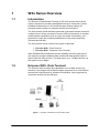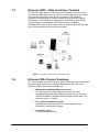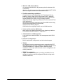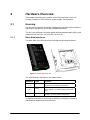
1
W3x Series
Fixed Wireless Terminals for WCDMA/HSPA Mobile Networks
Technical Product Description
Software Release R12
W3x Series
Fixed Wireless Terminals for WCDMA/HSPA Mobile Networks
Technical Product Description
Software Release R12
Abstract
This document describes the Ericsson’s Fixed Wireless Terminals (FWT),
the W3x product series.
© Ericsson AB - 2008 All Rights Reserved
Disclaimer
No part of this document may be reproduced in any form without the written
permission of the copyright owner.
The contents of this document are subject to revision without notice due to
continued progress in methodology, design, and manufacturing. Ericsson
shall have no liability for any error or damages of any kind resulting from
the use of this document.
2
221 02-FGB 101 544 Uen A - September 2008
Contents
1
W3X SERIES OVERVIEW.........................................................7
1.1
1.2
1.3
1.4
INTRODUCTION ............................................................................7
ERICSSON W30 - DATA TERMINAL ................................................7
ERICSSON W35 – DATA AND VOICE TERMINAL..............................8
ERICSSON W3X FEATURE SUMMARY ............................................8
2
HARDWARE OVERVIEW .......................................................10
2.1
2.1.1
2.1.2
2.1.3
2.1.4
2.1.5
2.1.6
2.2
2.2.1
2.2.2
2.2.3
2.3
2.3.1
2.3.2
HOUSING ...................................................................................10
Back Side Interfaces ................................................................10
Left Side Interfaces ..................................................................11
Right Side Interface .................................................................11
LED Indicators .........................................................................12
SIM/USIM Interface..................................................................13
Mounting ..................................................................................13
ANTENNAS.................................................................................14
Internal UMTS/GSM Antennas ................................................14
External UMTS/GSM Antennas ...............................................14
Internal WLAN Antennas .........................................................15
POWER SUPPLY.........................................................................15
Power Adapter .........................................................................15
Battery Backup (W35)..............................................................15
3
INTERFACES OVERVIEW......................................................16
3.1
3.1.1
3.1.2
3.1.3
3.1.4
3.1.5
3.2
3.2.1
3.3
3.4
3.4.1
3.5
UMTS/GSM RADIO INTERFACES ...............................................16
UMTS.......................................................................................16
GSM/GPRS/EDGE ..................................................................16
HSPA Throughput Rates .........................................................16
Data Transmission ...................................................................17
Frequency Bands.....................................................................18
WIRELESS LAN (WLAN) INTERFACE ..........................................18
Wireless Radio Channels.........................................................18
USB INTERFACE ........................................................................19
ETHERNET INTERFACE ...............................................................19
Built-in LED indicators..............................................................19
TELEPHONY INTERFACE (W35)...................................................20
4
MOBILE NETWORK FEATURES ...........................................21
4.1
4.2
4.3
4.3.1
4.4
4.5
4.6
4.6.1
4.6.2
4.7
4.7.1
4.7.2
PREFERRED ROAMING LIST (PRL) .............................................21
ACCESS POINT NAME (APN)......................................................21
MOBILE NETWORK .....................................................................21
Cellular Band Selection (W35 only) .........................................21
RSCP ALARM THRESHOLD ........................................................21
SET TIME/DATE FROM MOBILE NETWORK (W35 ONLY)................21
AUTHENTICATION .......................................................................21
PPP Client................................................................................22
PPP Authentication Type .........................................................22
SECURITY ..................................................................................22
PIN Lock ..................................................................................22
Operator Lock ..........................................................................22
221 02-FGB 101 544 Uen A – September 2008
3
4
5
DATA FEATURES...................................................................23
5.1
5.1.1
5.1.2
5.1.3
5.2
5.2.1
5.2.2
5.2.3
5.2.4
5.2.5
5.2.6
5.2.7
5.2.8
5.2.9
5.2.10
5.2.11
5.2.12
5.2.13
5.3
5.3.1
5.3.2
LAYER 2 FUNCTIONS ..................................................................23
L2TP ........................................................................................23
Bridging LAN and WLAN .........................................................23
WLAN Whitelist ........................................................................23
INTERNET PROTOCOL SERVICES ................................................23
IP Forwarding...........................................................................23
Static Routing...........................................................................23
DNS .........................................................................................23
DHCP Server ...........................................................................23
DHCP Relay.............................................................................24
SNTP .......................................................................................24
L2TP Tunneling........................................................................24
Firewall.....................................................................................24
NAT..........................................................................................25
UPnP IGD ................................................................................25
VPN Pass-Through ..................................................................25
IPsec/VPN Termination............................................................26
IP Quality of Service ................................................................26
USB SERVICES .........................................................................26
File Sharing..............................................................................26
Printer Sharing .........................................................................27
6
VOICE SERVICES (W35 ONLY) .............................................28
6.1
6.2
6.2.1
6.2.2
6.2.3
6.2.4
6.2.5
6.2.6
6.2.7
6.2.8
6.2.9
6.2.10
6.2.11
6.2.12
6.3
6.3.1
6.3.2
6.3.3
6.3.4
6.4
6.4.1
6.4.2
6.4.3
6.4.4
6.4.5
6.4.6
6.4.7
6.4.8
6.4.9
NATIONAL PROFILES ..................................................................28
GENERAL TELEPHONY FEATURES...............................................28
Inter Digit Timer .......................................................................28
Dial Tone Timeout....................................................................28
Congestion Tone Timeout........................................................28
Local Ringing Timeout .............................................................28
DTMF Duration ........................................................................28
On/Off-hook Timeouts..............................................................29
Hook Flash Time......................................................................29
CLIP .........................................................................................29
On Hold Ring ...........................................................................29
Tones and Signals Profile ........................................................29
Analog Settings Profile.............................................................30
Port Gain..................................................................................30
DIAL PROCESS ..........................................................................30
Dial Plan...................................................................................30
Local Call Prefix .......................................................................30
Fixed Number Dialing ..............................................................30
Emergency Calls......................................................................31
SUPPLEMENTARY SERVICES ......................................................31
Call Waiting..............................................................................31
Call Management with R-codes ...............................................31
CLIR.........................................................................................31
Call Return ...............................................................................32
Delayed Hotline........................................................................32
Call Forwarding Unconditional .................................................32
Call Forwarding on Busy..........................................................32
Call Forwarding on No Reply ...................................................32
Call Forwarding Unreachable ..................................................32
221 02-FGB 101 544 Uen A - September 2008
6.4.10
6.4.11
CWI ..........................................................................................32
Message Waiting .....................................................................33
7
FAX SERVICE (W35 ONLY) ...................................................34
7.1
7.2
7.3
7.3.1
7.3.2
7.4
7.4.1
7.4.2
7.4.3
7.5
7.6
7.6.1
7.6.2
7.6.3
7.7
IMS USER AGENT ......................................................................34
IMS CALL SERVER .....................................................................34
MEDIA CODEC ...........................................................................34
G.711a-law / GG.711 u-law .....................................................34
T.38..........................................................................................34
TIMERS .....................................................................................35
SIP Timers ...............................................................................35
Registration Timers ..................................................................35
VoIP Session Timeout .............................................................35
SECURITY ..................................................................................35
MEDIA STREAM ..........................................................................35
Jitter Buffer...............................................................................35
Echo Canceller.........................................................................35
QoS..........................................................................................35
INTEROPERABILITY .....................................................................35
8
WIRELESS LAN (WLAN) FEATURES ...................................36
8.1
8.2
8.3
8.4
8.4.1
8.4.2
8.4.3
SSID.........................................................................................36
REGION .....................................................................................36
CHANNEL SELECTION.................................................................36
WIRELESS SECURITY .................................................................37
WEP.........................................................................................37
WPA / WPA2............................................................................37
Whitelist ...................................................................................37
9
CONFIGURATION AND MANAGEMENT...............................38
9.1
9.2
9.3
9.4
9.4.1
9.4.2
9.4.3
9.4.4
9.4.5
9.4.6
9.5
9.5.1
9.5.2
9.5.3
9.5.4
9.5.5
9.5.6
9.5.7
9.5.8
9.5.9
9.5.10
9.6
9.7
WEB USER INTERFACE...............................................................38
COMMAND LINE INTERFACE ........................................................38
ACCESS CONTROL .....................................................................38
MANAGEMENT TOOLS ................................................................38
Software Update ......................................................................38
Remote Management using TR-069........................................39
Backup and Restore Configuration ..........................................39
Reset to Default Configuration.................................................39
System Log ..............................................................................40
Fault Management ...................................................................40
INTERFACE STATUS AND STATISTICS ..........................................40
Basic System Information ........................................................41
LAN Interface ...........................................................................41
WAN Interface..........................................................................41
WAN Interface Statistics ..........................................................42
IPsec/VPN Tunnel State ..........................................................42
Firewall Status .........................................................................42
WLAN Interface........................................................................43
USB Interface...........................................................................43
Telephony Interface (W35 only)...............................................43
Power Management (W35 only) ..............................................43
SECURITY MANAGEMENT ...........................................................43
TEMS INVESTIGATION SUPPORT ................................................43
221 02-FGB 101 544 Uen A – September 2008
5
6
10
REGULATORY INFORMATION .............................................45
10.1
10.2
10.3
10.4
10.5
10.6
10.7
10.8
APPROVALS ...............................................................................45
WIFI COMPLIANCE .....................................................................45
ROHS COMPLIANCE ..................................................................45
USB COMPLIANCE .....................................................................45
WEEE DIRECTIVE .....................................................................45
SAR..........................................................................................45
ENVIRONMENTAL .......................................................................45
INTENDED USE ..........................................................................46
11
ACRONYMS AND ABBREVIATIONS.....................................47
221 02-FGB 101 544 Uen A - September 2008
1
W3x Series Overview
1.1
Introduction
The Ericsson Fixed Wireless Terminal (FWT) W3x product series is the
superior solution for providing broadband services to areas with no fixed
broadband infrastructure in a cost efficient way utilizing existing 3G
powered mobile networks. It replaces the W2x product series.
The W3x product series facilitates protected, high-speed Internet access for
multiple users in home and small or branch office environments. It includes
advanced data capabilities such as router and switch functionality, and
provides the users with multiple possibilities for local area connectivity
(Ethernet and WLAN).
The W3x product series consist of two types of terminals:
•
•
Ericsson W30 – Data Terminal
Ericsson W35 – Data and Voice Terminal
With WCDMA/HSPA WAN radio access capability the W3x products are
well suited to provide broadband data access with data speeds similar to
that of fixed line DSL services. The data rate is up to 7.2 Mbps and the uplink speed is up to 2Mbps.
1.2
Ericsson W30 - Data Terminal
The Ericsson W30 provides data capabilities such as data access (e.g.
Internet) in the respect that it allows multiple computers to be connected to
the terminal using Ethernet or wireless LAN (WLAN). It also supports file
and printer sharing via the USB port.
Figure 1 - Overview of Interfaces for the Ericsson W30
221 02-FGB 101 544 Uen A – September 2008
7
1.3
Ericsson W35 – Data and Voice Terminal
The Ericsson W35 data and voice terminal incorporates the same set of
functions and data features as the Ericsson W30. Additionally, this model
also includes high quality voice and fax services via the telephony
interfaces. A broad range of network related services such as Prepaid
Subscription, CLI (Calling Line Identification), Call Waiting, Call Barring,
Call Forwarding, and Multiparty Conference Calls are available.
WCDMS/HSPA radio access is well suited for combined and efficient data
and voice transmission over the mobile network.
Figure 2 - Overview of Interfaces for the Ericsson W35
1.4
Ericsson W3x Feature Summary
The Ericsson W3x terminals feature the latest technology, which makes the
terminals highly suitable for everyday broadband services. The main
features of the Ericsson W3x terminals are:
8
•
Multimode broadband WAN connectivity;
The W3x terminals support antenna diversity and have
WCDMA/HSPA (850/1900/2100 MHz) as primary access and
GSM/GPRS/EDGE (850/900/1800/1900 MHz) as fall-back. The
data rate is up to 7.2 Mbps.
•
Four ports Fast Ethernet switch;
for wired LAN connectivity with rate auto-negotiation and
MDI/MDIX auto-detection support.
•
One USB 2.0 port;
for file and printer sharing.
221 02-FGB 101 544 Uen A - September 2008
•
Wireless LAN Access Point;
An integrated WLAN 802.11b/g access point for wireless LAN
connectivity.
Wireless security features including standard WLAN WEP, WPA,
WPA2, encryptions and MAC Association Control.
•
Flexible networking capabilities;
Comprehensive set of networking and IP protocols such as
bridging, routing, DNS, DHCP server/relay, SNTP, and NAT.
L2TP tunneling providing a mechanism for tunneling Ethernet
frames between two peers over an existing network.
VPN pass-through supporting VPN protocols for standard IPsec
VPN applications.
IPsec/VPN termination supporting one IPsec/VPN tunnel using
Site-to-Site configuration (Tunnel mode).
Stateful packet filtering firewall.
QoS feature for outgoing IP traffic via the WAN interface.
•
Voice and fax services (W35 only);
High quality voice and fax services via the telephony interface.
Fax service using SIP and the T.38 protocol.
•
Administration and Management;
Local and remote administration and management with SSH2
support.
•
End-user Configuration
Built-in web based configuration tool with wizard support.
•
TR-069
An integrated remote management agent supporting the CPE
WAN Management Protocol (CWMP) as specified in DSL Forum
TR-069 Amendment II. Supports remote software image
installation, shell script execution and a set of configuration and
status parameters.
•
TEMS™ Investigation
Support for TEMS Investigation providing possibilities for the
operator to perform real-time diagnostics check and log radio
interface behaviors.
221 02-FGB 101 544 Uen A – September 2008
9
2
Hardware Overview
This chapter describes the hardware of the W3x terminals in terms of
housing, interfaces, LED indicators, power supply, and antennas.
2.1
Housing
The housing on the W3x terminals is designed to be either wall mounted or
standing on the desk by use of the provided table stand.
The unit (not mounted in the table stand) weights approximately 380 gr and
measures 185 mm (H) x 106 mm (W) x 45 mm (D).
2.1.1
Back Side Interfaces
The back side of the W3x terminals includes the following interfaces:
Figure 3 - Ericsson W35 back side
The interfaces are described in the tables below:
Interface
Type
Function
Ethernet
1-4
4 x RJ45
Ethernet LAN connectors for connecting the unit
to client PCs or an Ethernet switch/hub.
12 VDC/
2A
4 pins
Power inlet for connecting the provided power
supply adapter or an external battery pack (W35
only).
Reset button
Switch
A small hole in the housing. Used to reset the
terminal to its factory default configuration.
In addition to the above, the Ericsson W35 also includes the following
interfaces for telephony and fax services:
10
221 02-FGB 101 544 Uen A - September 2008
2.1.2
Interface
Type
Function
Phone
RJ11
Phone connector for connecting a standard
analog phone.
Phone/
Fax
RJ11
Phone connector for connecting a standard
analog phone or fax. This port is dedicated for fax
connection.
Left Side Interfaces
The left side of the W3x terminals is equipped with the following interfaces:
Figure 4 - W3x terminals left side
The table below describes the interfaces:
Interface
Type
Function
SIM
SIM card
holder
SIM card interface.
USB
USB-A
USB connector, for connecting USB device(s) to
the unit, e.g. printer or mass storage.
Button
2.1.3
For future use.
Right Side Interface
The right side of the W3x terminals is equipped with an MCX antenna
connector for connecting an optional external antenna. See section 2.2.2
for further information.
Figure 5 – W3x terminals right side
221 02-FGB 101 544 Uen A – September 2008
11
2.1.4
LED Indicators
The front panel of the W3x terminals includes a signal strength indicator,
LED indicators and a Standby LED/button as described below.
Figure 6 - W30 (to the left) and W35 LED Indicators
2.1.4.1
Signal Strength Indicator
The signal strength indicator shows the strength of the signal from the
mobile network (UMTS, HSPA or GSM). The more segments displayed in
the bar graph, the stronger the signal.
The symbol in the centre of the graph (
) indicates the mobile network
connection. When 3G is displayed there is a connection to a UMTS
network. 3G with a + indicates connection to a HSPA network. When
nothing is displayed there is a connection to a GSM/GPRS/EDGE network.
2.1.4.2
W30 LED Indicators
The Ericsson W30 terminal has the following LED indicators:
Symbol
Color
Function
Blue
Unlit
Message waiting in WUI.
No message(s) in WUI.
Blue
Unlit
The Wireless LAN is active.
The Wireless LAN is inactive.
Blue
Unlit
Connection to Internet established.
No Internet connection.
WUI
Wireless LAN
Internet
12
221 02-FGB 101 544 Uen A - September 2008
2.1.4.3
W35 LED Indicators
The following LED indicators are visible on the front of the Ericsson W35
terminal:
Symbol
Color
Function
Blue
Unlit
Message waiting in WUI.
No messages in WUI.
Blue
Unlit
Voice message is available.
No voice message(s) available.
Blue
Unlit
The Wireless LAN is active.
The Wireless LAN is inactive.
Blue
Unlit
Connection to Internet established.
No Internet connection.
Blue
Unlit
A connected phone is off-hook.
A connected phone is on-hook.
WUI
Message
Wireless LAN
Internet
2.1.4.4
Standby LED/Button
The Standby
function:
2.1.5
LED/button at the bottom on the front has the following
Blue
The unit is powered on.
Red
The unit is in Standby mode, which happens when running on
battery power (W35) or when the Standby button is pressed.
SIM/USIM Interface
The W3x terminals have a plug-in SIM/USIM card connection supporting
1.8, 3 and 5V SIM.
2.1.6
Mounting
The W3x terminals can be wall mounted using the key holes on the back of
the unit.
Figure 7 - W3x wall mounting
221 02-FGB 101 544 Uen A – September 2008
13
The W3x terminals can also be placed on flat surface using the provided
table stand:
Figure 8 - W3x terminal in table stand
2.2
Antennas
The W3x terminals are equipped with internal/external antennas as
described in the following subsections.
2.2.1
Internal UMTS/GSM Antennas
The W3x terminals support antenna diversity and have two internal
UMTS/GSM antennas of standard dipole type (omni-directional in the
horizontal plane) with a gain of 2 dBi.
The antennas are penta-band supporting the 850/900/1800/1900/2100
MHz frequency bands.
2.2.2
External UMTS/GSM Antennas
The W3x terminals are equipped with an MCX antenna connector for
connecting an optional external antenna available as an accessory and as
described below.
2.2.2.1
Window Antenna
An UMTS/GSM window antenna is available as an accessory.
This antenna is a penta-band antenna operating in the 824-960 and 17102170 MHz frequency bands with a gain of 2.15 dBi.
2.2.2.2
Roof Antenna
An UMTS/GSM roof antenna is available as an accessory.
This antenna is a penta-band antenna operating in the 824-960 and 17102170 MHz frequency bands with a gain of 11 dBi with 0.5 dBi variation over
specified bands.
14
221 02-FGB 101 544 Uen A - September 2008
2.2.3
Internal WLAN Antennas
The W3x terminals have two internal WLAN antennas (omni-directional).
The antennas are mounted orthogonally for best performance.
2.3
Power Supply
The W3x terminals can be powered from:
•
•
2.3.1
AC Mains via an external AC/DC power adapter (10-28 VDC)
Battery pack (backup).
Power Adapter
The provided power adapter has the following characteristics:
Input: 100-240V AC, 50-60 Hz, 3 pole AC inlet connector (IEC 320 power
inlet).
Output: 12 VDC.
Power consumption: 7.0 W (typical) and 11.4 W (maximum) for W30 and
9.0 W (typical) and 12 W (maximum) for W35.
National power plugs are available for EU, UK, US and AU.
Figure 9 - Power adapter with national plugs
2.3.2
Battery Backup (W35)
The W35 terminal can be powered with a rechargeable battery pack to
provide voice redundancy in the event of a total mains power failure. Talk
time is typically 3-4 hours. The battery pack is available as an accessory
and is inserted between the AC/DC adaptor and the W35 terminal.
Figure 10 - Battery pack
A battery charger that recharges the battery is located in the battery pack.
221 02-FGB 101 544 Uen A – September 2008
15
3
Interfaces Overview
This chapter provides an overview of the W3x interfaces.
3.1
UMTS/GSM Radio Interfaces
The W3x terminals support UMTS and GSM/GPRS/EDGE radio interfaces
where UMTS is the primary interface.
3.1.1
UMTS
The W3x terminals support UMTS 850/1900 MHz and 2100 MHz frequency
bands.
The UMTS interface supports the following characteristics:
•
•
3.1.2
WCDMA
HSPA, Category 1-8 and 11/12, up to 7.2 Mbps (downlink) and
Category 3 and 5, up to 2.0 Mbps (uplink)
GSM/GPRS/EDGE
The W3x terminals support GSM/GPRS/EDGE 850/900/1800/1900 MHz
frequency bands.
The GPRS/EDGE interface supports the following characteristics:
•
•
•
3.1.3
GPRS, multi-slot class 12 CS 1-4
EDGE, multi-slot class 12, MCS 1-9
Dual Transfer Mode (DTM)
HSPA Throughput Rates
The W3x terminals peak download speed is rated up to 7.2 Mbps and the
peak up-link speed is 2.0 Mbps, software upgradeable to 5,76.
However peak downlink speeds are only possible with normal usage in a
cell and with optimal signal conditions. Typical download speeds
experienced by the users with multiple concurrent voice and data users in
the cell, ranges from 0.6 Mbps to 5.0 Mbps on average with current W3x
series radio configuration according to simulations in urban and suburban
environments.
16
221 02-FGB 101 544 Uen A - September 2008
3.1.4
Data Transmission
The W3x terminals offer packet switched data transmission. The table
below summarizes typical and theoretical data rates:
Theoretical
Typical
Packet data service max data
data rate
rate
Category/
Multislot class
Upload
2.0 Mbps
300-800 kbps
Category 3, 5
Download
7.2 Mbps
600-5000 kbps
Category
1-8, 11 and 12
Upload
384 kbps
Over 300 kbps
Download
384 kbps
Over 300 kbps
Upload
118 kbps
50-60 kbps
Download
236 kbps
100-130 kbps
(with bursts
over 200 kbps)
Upload
43 kbps
20 kbps
Download
86 kbps
40 kbps
HSPA
WCDMA
EDGE
GPRS
221 02-FGB 101 544 Uen A – September 2008
Multislot
class 12
MCS 1-9
Multislot
class 12
CS 1-4
17
3.1.5
Frequency Bands
The W3x terminals support frequency bands as shown in the table below:
3.2
Band
Frequencies
(MHz)
Conducted Rx
sensitivity
(dBm)
Conducted
Transmit
Power
(dBm)
Band I
UMTS 2100
Tx: 1920-1980
Rx: 2110-2170
< -109
+23
Band II
UMTS 1900
Tx: 1850-1910
Rx: 1930-1990
< -109
+23
Band V
UMTS 850
Tx: 824-849
Rx: 869-894
< -110
+23
GSM 850
Tx: 824-849
Rx: 869-894
< -106
EGSM 900
Tx: 880-915
Rx: 925-960
< -106
DCS 1800
Tx: 1710-1785
Rx: 1805-1880
< -106
PCS 1900
Tx: 1850-1910
Rx: 1930-1990
< -106
+32 (GMSK)
+27 (8PSK)
+29 (GMSK)
+26 (8PSK)
Wireless LAN (WLAN) Interface
The W3x terminals act as wireless Access Point (AP) supporting IEEE
802.11b/g standards.
IEEE 802.11b operates in the unlicensed 2.4 GHz band and can
theoretically achieve 11 Mb/s. In practice, throughput around 25 Mb/s is
more realistic.
The WLAN interface can be configured to run in combined b/g mode
(supporting 802.11b and g clients at the same time) or as b-only or g-only.
The b-mode-legacy is also supported.
The transmit power is configurable and is limited to maximum 20 dBm.
For wireless security the W3x terminals support WEP, WPA-PSK, WPA2PSK and MAC Association Control.
3.2.1
Wireless Radio Channels
The table below shows the IEEE 802.11 channels and their corresponding
center frequencies:
18
221 02-FGB 101 544 Uen A - September 2008
Channel
Number
Channel
Frequency
Geographic Indoor Usage
1
2412 MHz
US (United States), CA (Canada), ETSI (ETSI
Countries), SI (Singapore), AS (Australia), NZ
(New Zealand), SA (South Africa), MA (Malaysia)
2
2417 MHz
US, CA, ETSI, SI, AS, NZ, SA, MA
3
2422 MHz
US, CA, ETSI, SI, AS, NZ, SA, MA
4
2427 MHz
US, CA, ETSI, SI, AS, NZ, SA, MA
5
2432 MHz
US, CA, ETSI, SI, AS, NZ, SA, MA
6
2437 MHz
US, CA, ETSI, SI, AS, NZ, SA, MA
7
2442 MHz
US, CA, ETSI, SI, AS, NZ, SA, MA
8
2447 MHz
US, CA, ETSI, SI, AS, NZ, SA, MA
9
2452 MHz
US, CA, ETSI, SI, AS, NZ, SA, MA
10
2457 MHz
US, CA, ETSI, SI, AS, NZ, SA, MA
11
2462 MHz
US, CA, ETSI, SI, AS, NZ, SA, MA
12
2467 MHz
ETSI, SI, AS, NZ, SA, MA
13
2472 MHz
ETSI, SI, AS, NZ, SA, MA
Radio scanning makes the W3x terminals capable of sensing other access
points of the allowed channel.
3.3
USB Interface
The W3x terminals include a USB 2.0 Host Controller with one external
type A port supporting both full speed and high-speed.
The USB interface supports one low power device per port hence the
maximum power consumption of a device is 100 mA.
Maximum practical cable length for USB is 5 m.
3.4
Ethernet Interface
The W3x terminals include a Fast Ethernet switch with four (4) external
LAN 10/100BaseTx ports (female RJ45) for connection to PC equipment.
Each Ethernet port supports rate auto-negotiation and MDI/MDIX autodetection.
The MDI/MDIX auto detection allows the user to plug in either a straight or
crossed Ethernet cable.
Maximum cable length for Ethernet is 100 m.
3.4.1
Built-in LED indicators
Each Ethernet connector has two built-in indicators.
The left indicator shows the speed of data traffic between the W3x terminal
and the connected client. If the speed is 100 Mbps, the indicator is green.
When the indicator is unlit, the speed is 10 Mbps.
221 02-FGB 101 544 Uen A – September 2008
19
The indicator to the right is green when a LAN connection is established
and flashes to show data traffic activity.
3.5
Telephony Interface (W35)
The Ericsson W35 includes dual POTS interface (FxS). The port marked
“Phone” is the primary port to be used for making phone calls. The other
port (marked “Phone/Fax”) is intended for fax machines and
complementary telephony services.
The ports are intended for on premises phones and should typically be
connected to devices within one building. Short loops (max 500Ω) are
supported.
The maximum ringing load for each port is 3 REN (corresponding to three
(3) old fashioned phones with mechanical bells or twenty (20) modern
phones with electronic ringing).
Characteristic impedance, gain, current etc of the ports are controlled by
software. DTMF dialing is supported. The ports have protection to prevent
the unit to be damaged by ESD (Electro Static Discharge).
20
221 02-FGB 101 544 Uen A - September 2008
4
Mobile Network Features
4.1
Preferred Roaming List (PRL)
The PRL contains information regarding the allowed systems and
frequency bands. The PRL structure and coding is defined in TIA/EIA IS683.
The W3x terminals use the configured PRL region during the system
selection and acquisition process, initially and when roaming.
4.2
Access Point Name (APN)
The APN can be set manually or automatically based on the SIM card’s
MCC and MNC. The W3x terminals include a pre-defined list with
commonly used APNs.
4.3
Mobile Network
The W3x terminals connect to the UMTS (3G) network when it is available
and, if enabled, uses the GSM/GPRS/EDGE (2G) network as fallback. It is
possible to individually enable/disable the networks.
4.3.1
Cellular Band Selection (W35 only)
In Ericsson W35 it is also possible to individually enable/disable frequency
bands used for the connection; 850, 1900 and 2100 for the 3G network and
850, 900, 1800 and 1900 for the 2G network.
4.4
RSCP Alarm Threshold
For RSCP (Receive Signal Code Power) an alarm threshold can be set and
if the current RSCP level is below the threshold value, a critical event is
sent to the syslog and is also available on the remote syslog.
4.5
Set Time/Date from Mobile Network (W35 only)
The Ericsson W35 system time and date can be configured to be set from
the mobile network. When the celltime service is initially enabled it checks
and updates the time every 2 minutes for the first 20 minutes. After that, the
synchronization occurs every 15 minutes.
As an alternative synchronization with a remote NTP server can be used
(see section 5.2.6). This is also the way that the Ericsson W30 uses.
4.6
Authentication
Authentication towards the UMTS/GSM radio network can be done via PIN
code and/or PPP username and password.
221 02-FGB 101 544 Uen A – September 2008
21
4.6.1
PPP Client
The W3x terminals include a PPP client for WAN access. For
authentication both the PAP and CHAP protocols are supported.
4.6.2
PPP Authentication Type
This feature enables the possibility to change the authentication protocol
(CHAP or PAP) when authentication against the cellular network is done
using a RADIUS server.
4.7
Security
The basic security feature of the W3x terminals are the same as any GSM
phone, using a PIN code that comes with the subscription SIM card. The
PIN code is simply entered via the WUI or via phone handset (only W35).
To simplify usage, the W3x terminals have an auto PIN feature that
requires the PIN code only to be entered the first time the unit is used or
upon changing the SIM card.
Additionally the W3x terminals provide security features that prevent
unauthorized use of the SIM card and the unit, which can be customized if
required.
4.7.1
PIN Lock
This feature locks the SIM card to a unique unit by changing the PIN code
to a new random value. As a result, the SIM card cannot be used in another
terminal unless the PUK code is known.
4.7.2
Operator Lock
This feature allows for the use of SIM cards in the terminal that meet
specific criteria. This would normally be configured to allow only a specific
operator or group of operators SIM cards.
The W3x terminals can be locked to only accept SIM cards based on one
or more of the following:
•
•
Mobile Country Code (MCC)
Mobile Network Code (MNC)
MCCs are defined in ITU E.212 (“Land Mobile Numbering Plan”) for use in
identifying mobile stations in wireless telephone networks. A MCC is often
used in combination with a Mobile Network Code (MNC) in order to
uniquely identify a network operator.
Both the MCC and MNC are part of the International Mobile Subscriber
Identity (IMSI) number, which uniquely identifies a particular subscriber,
and is stored on the SIM card.
From the WUI it is possible to enter a secret “Unlock Operator Lock” code
(which is a random code generated at production).
22
221 02-FGB 101 544 Uen A - September 2008
5
Data Features
5.1
Layer 2 Functions
5.1.1
L2TP
The W3x terminals support one L2TP tunnel. The LAN/WLAN is bridged
into the tunnel using the BCP (Bridging Control Protocol). See also section
5.2.7 – L2TP Tunneling.
5.1.2
Bridging LAN and WLAN
The W3x terminals support bridging/switching traffic between the LAN and
WLAN interfaces.
5.1.3
WLAN Whitelist
The W3x terminals support WLAN whitelist, also known as “MAC
Association Control” or “MAC Access List”. Up to 20 WLAN MAC
addresses can be added to the list and the use of the whitelist is possible to
enable/disable.
5.2
Internet Protocol Services
The Internet Services in the W3x terminals are based on the Internet
Protocol version 4 (IPv4).
5.2.1
IP Forwarding
The W3x terminals support IP forwarding and employs ingress traffic
filtering on both the LAN and the WAN interfaces.
5.2.2
Static Routing
The W3x terminals support destination based static routing. Static routes
can be added to the routing table to ensure packets are forwarded to their
correct destination.
5.2.3
DNS
The W3x terminals include a DNS proxy server which responds to DNS
requests from the local LAN/WLAN. It contains a small database of local
host names and addresses supplied by client DHCP requests.
In addition it also caches requests to remote DNS servers.
5.2.4
DHCP Server
The W3x terminals include a DHCP server for LAN/WLAN interfaces.
The DHCP server maintains a pool of IP addresses and distributes them to
LAN/WLAN hosts whenever they are switched on. It also puts the
hostname, supplied by the client DHCP request, in the local DNS proxy.
221 02-FGB 101 544 Uen A – September 2008
23
5.2.5
DHCP Relay
The W3x terminals support DHCP relay. As a DHCP relay agent, the
terminals forward requests for IP addresses from LAN/WLAN hosts to a
DHCP server (at the ISP’s location) and then returns the IP information
from the DHCP server to the hosts.
5.2.6
SNTP
The W3x terminals include a SNTP client which provides a way to
synchronize the device’s own time of day setting with a remote NTP server.
It is possible to specify up to three (3) different SNTP servers (for fallback).
As an alternative the time can also be fetched from the mobile network (see
section Error! Reference source not found.).
5.2.7
L2TP Tunneling
The W3x terminals support one L2TP tunnel providing a mechanism for
tunneling Ethernet frames between two peers over an existing network
(usually the Internet). The LAN/WLAN is bridged into the tunnel using BCP
over PPP over L2TP.
The BCP/PPP/L2TP tunnel can be used to connect a branch office LAN to
a corporate office LAN over a 3G/HSPA network connection.
5.2.8
Firewall
The W3x terminals include a stateful packet filtering firewall (using Linux
Kernel iptables) applicable between the WAN and WLAN/LAN interfaces.
5.2.8.1
Firewall Rules
Firewall rules are used to specify matching values that a packet must have
for this rule to apply to the packet. These values include the following:
•
•
•
•
•
Source or destination IP address
Source or destination port or range of ports
Transport protocol (UDP, TCP, IGMP, all).
Incoming/outgoing interface
Action; accept, drop, reject, or dscp:0xXX
Up to 50 simultaneous firewall rules can be defined and it is also possible
to use the operation ”NOT” when defining rules.
5.2.8.2
Packet Drop and Reject
A packet can be either dropped or rejected based on the outcome of the
packet classification. If the unit rejects a packet, the sender receives the
appropriate ICMP message. If the unit drops a packet, it silently discards
the packet.
5.2.8.3
Denial of Service (DoS)
A DoS attack is an attempt by an attacker to prevent legitimate hosts from
using a service. The W3x terminals support rate limit of ICMP packets (02000) and TCP SYN segments (0-2000).
24
221 02-FGB 101 544 Uen A - September 2008
5.2.9
NAT
The W3x terminals support dynamic one-to-many NAT - also known as
NAPT. NAPT translates the source IP address of the LAN to the public
WAN IP address. It also changes the source port (UDP or TCP) or the
ICMP for the WAN to LAN flow. Port translation allows several LAN devices
to be connected to the WAN through one public IP address.
5.2.9.1
NAT Port Forwarding
The NAT Port Forwarding feature, sometimes referred to as Virtual Server,
redirects traffic from the WAN side to a server on the LAN side.
The Port Forwarding feature requires that the W3x terminal has a public IP
address for Port Forwarding requests from the Internet to be handled
correctly.
5.2.9.2
NAT ALGs
An ALG enables the transfer of specific application streams through NAT.
This is enabled by creating dynamic holes in NAT and changing IP
addresses in network protocol headers, and if a secondary port is required,
the ALG will open one.
The W3x terminals include NAT ALGs for the following protocols:
•
•
•
•
•
FTP
TFTP
RTSP
SIP
PPTP
The included ALGs can be enabled/disabled individually and do not require
any additional configuration.
5.2.10
UPnP IGD
The W3x terminals support the UPnP standard with respect to the Internet
Gateway Device (IGD) profile, used by Microsoft Messenger (among
others) to configure port forwarding in a NAT router.
5.2.11
VPN Pass-Through
The W3x terminals support VPN pass-through from a client on the LAN
connecting to a VPN server on the Internet without any configuration.
Supported protocols are IPsec and PPTP (Microsoft VPN) with the
following limitations:
•
•
The IPsec client and server must support NAT-T (NAT Traversal).
Only one client at a time can use PPTP, unless the PPTP ALG is
enabled.
Other VPN pass-through configurations, such as a VPN server residing on
the W3x LAN, are also possible provided the appropriate ports/protocols
are forwarded.
221 02-FGB 101 544 Uen A – September 2008
25
5.2.12
IPsec/VPN Termination
The W3x terminals support one IPsec/VPN tunnel using Site-to-Site
configuration (Tunnel mode). An IPsec VPN serves as a point-to-point
tunnel interface allowing the W3x terminals to send some or all of its WAN
traffic across an encrypted tunnel rather than in clear text.
ESP is used to encrypt the payload part of an IP packet and ensures origin
authenticity, integrity and confidentiality. 3DES and AES-128 are used as
encryption algorithms and SHA-1 and MD5 as hash algorithms. NAT
traversal is supported when IPsec is enabled.
5.2.12.1
IKE
IKE is the protocol for setting up a shared session secret from which
cryptographic keys then can be derived. The W3x terminals support IKE v1
with pre-shared key as method of authentication. 3DES and AES-128 are
used as encryption algorithms and SHA-1 and MD5 as integrity/hash
algorithms. Group 2 is supported as Diffie-Hellman group identifier.
5.2.13
IP Quality of Service
The QoS service in the W3x terminals support the Stochastic Fair Queuing
(SFQ) scheduling algorithm which makes sure that no single session can
dominate outgoing bandwidth.
The QoS feature applies for upstream traffic only.
5.3
USB Services
The W3x terminals may function as a network storage device or printer
server for LAN/WLAN hosts using Windows File and Printer sharing (also
known as SMB or CIFS).
When an external hub is connected to the USB connector, the W3x
terminals support connection of up to two storage devices and one printer
at the same time. Both USB 1.1 and 2.0 (full speed and high-speed) are
supported.
The W3x terminals use Samba as the base to implement file and printer
sharing through SMB/CIFS.
5.3.1
File Sharing
A USB disk drive or memory stick that is connected to the USB connector
on the W3x terminals is automatically mounted and shared over the LAN
(and WLAN, if enabled).
The included files are shared with all devices belonging to the same
workgroup and all users have full read/write (including delete) access to the
shared files. Only the first partition of a storage device is automatically
mounted and shared.
The file system on a shared device needs to be of a supported type.
Currently the following types are supported:
26
221 02-FGB 101 544 Uen A - September 2008
•
•
•
•
5.3.2
FAT; Microsoft legacy file system from MS-DOS with 8.3
character filename system
FAT32; Microsoft Windows 95 file system based on FAT but with
long filename system
ext2; second extended file system, the standard Linux file system
ext3; like ext2 but with journaling support.
Printer Sharing
When a printer is connected to the USB connector, the W3x terminals
automatically create a local UNIX printer that is shared over the LAN (and
WLAN, if enabled) using SMB/CIFS protocol.
221 02-FGB 101 544 Uen A – September 2008
27
6
Voice Services (W35 only)
The Ericsson W35 provides voice services via the telephony line interface
with high speech quality.
6.1
National Profiles
Country specific settings for the telephony services (based on the SIM
card’s MCC) can automatically be loaded when the Ericsson W25 is
started. These settings include parameters for the POTS interface (i.e.
impedance, ringing signals, cadence, levels etc), CLIP service
configuration, and settings for supplementary services.
National profiles for the following countries are currently supported:
•
•
•
•
•
•
•
•
6.2
Austria (AT)
Australia (AU)
Spain (ES)
Hungary (HU)
New Zealand (NZ)
Sweden (SE)
United Kingdom (UK)
United States (US).
General Telephony Features
The following subsections describe telephony related features that can be
customized in the Ericsson W35:
6.2.1
Inter Digit Timer
The Inter Digit Timer (IDT) specifies the duration the Ericsson W35 waits to
detect the next digit when dialing. After this period, no more digits are
expected to arrive and an attempt to establish the call is done.
6.2.2
Dial Tone Timeout
The dial tone timeout specifies for how long the system will wait for the
caller to input the first digit after going off-hook.
6.2.3
Congestion Tone Timeout
The congestion tone timeout determines for how long a congestion tone is
to be played.
6.2.4
Local Ringing Timeout
The local ringing timeout specifies the maximum time a call will attempt to
connect if the B-Party does not answer.
6.2.5
DTMF Duration
This setting determines the DTMF digit signal duration for the regenerated
DTMF signals from the network side towards the POTS port.
28
221 02-FGB 101 544 Uen A - September 2008
The duration of the DTMF-tones sent from the Ericsson W35 towards the
network is determined by the TE and the network settings and are not
configurable in the Ericsson W35.
6.2.6
On/Off-hook Timeouts
These settings determine the time needed for the Ericsson W35 to consider
the phone to be on- or off-hook.
6.2.7
Hook Flash Time
This setting controls the “Hook Flash” feature which on most modern
phones is implemented as a button that simulates a quick off-hook/onhook/off-hook cycle. This is the same function as quickly tapping at the
hook on an old style phone, also called Register Recall (the R-button).
The setting specifies the time-window in which the on-hook condition exists
in order to be interpreted as a hook flash.
6.2.8
CLIP
The Ericsson W35 supports CLIP (Calling Line Identification Presentation)
service in both on-hook and off-hook states using the DTMF and FSK
protocols, supporting both ETSI and Bellcore standards.
It is possible to configure a country specific profile for the CLIP service.
An international prefix for the CLIP service is also configurable. This setting
determines how a “+” character should be displayed (e.g. 00).
6.2.9
On Hold Ring
This setting specifies what will happen if the user goes on-hook with an
active call placed on-hold. If enabled, the user will be notified about a
remaining on-hold call ring signal. If disabled, all calls will be disconnected
when going on-hook.
6.2.10
Tones and Signals Profile
The tones and signals profile includes local settings for ringing signals and
information tones generated by the Ericsson W35 (in opposite to the tones
received from the network).
Tones and signals profiles for the following countries are currently
supported:
•
•
•
•
•
•
•
•
Austria (AT)
Australia (AU)
Spain (ES)
Hungary (HU)
New Zealand (NZ)
Sweden (SE)
United Kingdom (UK)
United States (US).
These settings might be overridden by the operator network.
221 02-FGB 101 544 Uen A – September 2008
29
6.2.11
Analog Settings Profile
The analog settings profile defines physical settings for the FXS ports
including impedance and nominal gain settings.
Analog settings profiles for the following countries are currently supported:
•
•
•
•
•
•
•
•
6.2.12
Austria (AT)
Australia (AU)
Spain (ES)
Hungary (HU)
New Zealand (NZ)
Sweden (SE)
United Kingdom (UK)
United States (US).
Port Gain
For each of the FXS ports (“Phone” and “Phone/Fax”), the receiving and
transmitting gain can be adjusted, with respect to the nominal relative level.
6.3
Dial Process
The Ericsson W35 supports E.164 numbering. E.164 numbers can have a
maximum of 15 digits and are usually written with a + prefix.
There are three ways to indicate that the dialed number sequence is
complete:
•
•
•
Dialing the EON key (e.g. # or *) immediately sends the call.
An Inter Digit Timer (IDT) is used to check the dialing process.
A specified number of digits must be dialed before the call is
placed.
The EON key is configurable as well as the IDT.
6.3.1
Dial Plan
The dial plan consists of a number of rules, defined using regular
expressions (ref. POSIX 1003.2). These rules are used to match dialed
digits, and provide also the ability to strip/append prefix and suffix digits.
6.3.2
Local Call Prefix
A local prefix can automatically be added to a dialed local number. This is
useful in places where the PSTN does not require the local prefix in local
calls.
6.3.3
Fixed Number Dialing
Fixed Number Dialing is supported when a SIM providing this service is
installed. When enabled, only calls to fixed numbers stored on the SIM are
allowed.
30
221 02-FGB 101 544 Uen A - September 2008
6.3.4
Emergency Calls
Emergency calls have its own dial plan and multiple numbers can be
configured.
It is possible to place an emergency call (e.g. 112) without having to enter a
PIN code, when the PIN lock feature is enabled, without a SIM card present
in the unit, or if the device is locked to the network by a specific MCC
and/or MNC. This ensures emergency calls will always be established
regardless of the configuration of the Ericsson W35.
Emergency numbers are handled as follows:
•
•
•
6.4
112 and 911 are always available (hard coded) and do not
depend on the defined dial plan.
If a SIM card is present, emergency number from the dial plan are
also used.
If no SIM card is present, the numbers 000, 08, 110, 999, 118 and
119 are also handled as emergency numbers.
Supplementary Services
The UMTS/GSM supplementary service codes (e.g. #67# etc) can be
configured with any service code in order to have the same service codes
as in a fixed network.
Supplementary services can only be used with a DTMF telephone
connected to the Ericsson W35.
The following subsections describe the supplementary services currently
supported.
6.4.1
Call Waiting
This service enables the caller to be notified of an incoming call during a
conversation. The subscriber can then answer, reject, or ignore the
incoming call.
6.4.2
Call Management with R-codes
This service enables the caller to interrupt an active call (placing the caller
on hold), make a new call and then subsequently, switch between the old
and new call. It is also possible to release either of the calls, putting all
three in a conference call or “break up” a conference call into two separate
calls again.
6.4.3
CLIR
The CLIR (Calling Line Identification Restriction) service enables a calling
party to prevent presentation of his telephone number to the called party.
The network operator can configure the default CLIR service state for a
specific subscriber to be either always restricted, temporary restricted or
temporary allowed.
221 02-FGB 101 544 Uen A – September 2008
31
6.4.4
Call Return
This service enables a user to call the last unanswered call by dialing a
configured service code.
6.4.5
Delayed Hotline
This service enables a user to call a particular number (hotline number) by
just lifting the handset and wait for a fixed period (delay).
The hotline number must be entered into the Ericsson W35 by the
customer prior to use. A prefix is added to the dial plan for the customer
hotline number.
Calls cannot be forwarded to emergency numbers.
6.4.6
Call Forwarding Unconditional
This service enables a user to immediately have all incoming calls
forwarded to another number.
When the service is active, the subscriber will hear a distinct dial tone when
attempting to make a call.
Due to configuration in most networks, calls cannot be forwarded to
emergency numbers or international numbers.
6.4.7
Call Forwarding on Busy
This service enables a user to have all incoming calls, which meet with
busy, forwarded to another number.
Due to configuration in most networks, calls cannot be forwarded to
emergency numbers or international numbers.
6.4.8
Call Forwarding on No Reply
This service enables a user to have all incoming calls, which meet with no
reply, forwarded to another number.
Due to configuration in most networks, calls cannot be forwarded to
emergency numbers or international numbers.
6.4.9
Call Forwarding Unreachable
This service enables a user to have all incoming calls, which meet with
unreachable, forwarded to another number.
Due to configuration in most networks, calls cannot be forwarded to
emergency numbers or international numbers.
6.4.10
CWI
The Ericsson W35 supports the CWI (Call Waiting Indication) service over
the POTS interface.
32
221 02-FGB 101 544 Uen A - September 2008
6.4.11
Message Waiting
The subscriber is alerted about new voice mail message(s) by the
) LED on the unit and by a special information tone that
Message (
plays when going off-hook.
The Message LED and tone is activated when a SMS message is received
from a pre-defined number configured in the terminal, i.e. the service
providers’ voicemail system. The LED and tone are deactivated when a
phone call is placed to a pre-defined number configured in the terminal, i.e.
the service providers’ voicemail number.
221 02-FGB 101 544 Uen A – September 2008
33
7
Fax Service (W35 only)
To enable Fax support over the WCDMA network, Ericsson W35 uses SIP
(Session Initiation Protocol).
The Ericsson W35 acts as a media gateway between the POTS interface
and the IP network and uses the T.38 protocol. To enable a fax call a SIP
server and PSTN gateway is required. The SIP server needs to support SIP
according to RFC 3261 and the media gateway needs to support SIP and
T.38.
The Ericsson W35 supports G3 fax as specified in ITU-T T.30 Annex A.
Older standards, as G1 and G2, and the newer superG3 (sometimes called
V.34fax) are not supported.
7.1
IMS User Agent
The IMS (SIP) User Agent is associated to the “Phone/Fax” port on the
Ericsson W35. This integrated User Agent controls VoIP sessions and
manages and controls the media streams by using the SIP protocol
towards the SIP Server and Media Gateway.
7.2
IMS Call Server
The IMS User Agent requires access to one or more IMS Call servers (also
called SIP proxy/servers). A list can be created with configuration details for
different SIP server/proxy settings and possibly an outbound proxy.
7.3
Media Codec
The Ericsson W35 supports the following CODECs:
•
•
•
7.3.1
G.711a-law (used for VoIP)
G.711u-law (used for VoIP)
T.38 (used for Fax services).
G.711a-law / GG.711 u-law
The G.711a-law and G.711u-law CODECs are used for VoIP and the
settings include Voice Activity Detection (VAD); enable/disable silence
suppression, and the RTP payload size.
7.3.2
T.38
The T.38 settings are used for Fax and even if the parameter name says
T.38 most of the items are basically T.30 settings.
Depending on radio network characteristics there might be a need for fine
tuning the T.38 parameters.
34
221 02-FGB 101 544 Uen A - September 2008
7.4
Timers
The following fax related timers can be configured in the Ericsson W35.
7.4.1
SIP Timers
Since the delay in the radio network is a little bit longer than in a wired
network, it might be needed to adjust the SIP timers (T1, T2, T4 and
transaction timeout) to better fit the network. The default values are
adjusted for the radio network, but might need some fine tuning.
7.4.2
Registration Timers
The registration timers are used when the Ericsson W35 sends a SIP
registration message to the SIP server/registrar.
7.4.3
VoIP Session Timeout
To avoid that the “Phone/Fax” port is used as a telephony port using VoIP it
is possible to restrict for how long a voice call is allowed. If no fax tones are
detected, i.e. switching over to T.38, within a certain time, the call is teared
down by the Ericsson W35.
7.5
Security
The Ericsson W35 authenticates towards the VoIP system using the HTTP
Digest Authentication mechanism.
7.6
Media Stream
Due to the procedure of setting up a fax call both G.711 and T.38 is
supported by the Ericsson W35. First a call is setup as a normal voice
connection (using G.711) before a switchover to T.38 is done (using SIP
Re-INVITE practices).
7.6.1
Jitter Buffer
To handle latency and jitter in the IP network the Ericsson W35 has a jitter
buffer. The access network contributes with most of the latency and jitter,
so to reduce this a HSPA connection is recommended.
7.6.2
Echo Canceller
To improve the fax transfer, the Ericsson W35 has an echo canceller in
accordance with G.168.
7.6.3
QoS
The outgoing VoIP related traffic will be prioritized before other traffic from
the Ericsson W35 to reduce the uplink delay and jitter.
7.7
Interoperability
The Ericsson W35 is interoperable with e.g. Broadsoft, which is included in
Ericsson’s IMT (IMS Multimedia Telephony). Other SIP servers and Media
Gateways should also work as long as they support SIP v2 (RFC 3261) and
T.38, but interoperability testing needs to be done to verify this.
221 02-FGB 101 544 Uen A – September 2008
35
8
Wireless LAN (WLAN) Features
The W3x terminals can be used as a wireless Ethernet router, connecting
to wireless PCs according to the IEEE 82.11b/g standards.
The WLAN interface can be enabled/disabled.
The preferred WLAN data rate can be configured to be either B-G-MIXEDMODE, G-MODE-ONLY, B-MODE-ONLY or B-MODE LEGACY.
To avoid interference with other wireless networks, the transmit power level
can be changed in the range 0 – 20 dBm.
8.1
SSID
The W3x terminals support single SSID. This SSID and a unique MAC
address are broadcasted in the beacon at regular intervals.
The SSID can be set (changed) with a maximum length of 32 alphanumeric
characters.
It is also possible to configure the SSID to be hidden. In this case the SSID
will not be broadcasted and local wireless clients will not find the SSID
when scanning the air.
8.2
Region
To make sure the W3x terminals transmit on correct radio frequencies
according to national regulations, the region where the device is used must
be stated.
The following regions are currently supported:
•
•
•
•
•
•
•
•
8.3
Europe (EU)
United States (US)
Canada (CA)
South Africa (SA)
Australia (AU)
New Zealand (NZ)
Malaysia (MA)
Singapore (SI).
Channel Selection
The channel number determines the channel used by the device to pass
traffic to clients. A channel number can be manually set and valid channels
numbers are 1-13 except if region is set to US or Canada when valid
channels are 1-11.
By enabling the “Automatic Channel Selection” feature, the radio will scan
each valid channel and automatically select a channel with no activity. If
36
221 02-FGB 101 544 Uen A - September 2008
there are not channels without activity, the one with the lowest activity is
selected (or random if lowest activity is equal). When this feature is
enabled, the W3x terminals will select the best channel upon every restart.
8.4
Wireless Security
Authentication and data encryption are used to restrict access to the
wireless network. Which authentication and encryption method that should
be used depends on what is supported by the connecting wireless
device(s).
Wireless security can be configured to be either “open” (no authentication
or encryption) or “closed” (meaning WEP-64, WEP-128, WPA, WPA2 or
WPA/WPA2 Mixed security). WPA/WPA2 Mixed security mode enables
connection of both WPA and WPA2 clients. See below for security details.
8.4.1
WEP
WEP enables wireless security using 64-bit or 128-bit data encryption.
WEP encryption requires a private network key. Each device in the wireless
network has to be manually configured with this key.
8.4.2
WPA / WPA2
WPA is a 256-bit data encryption method with keys that dynamically
change over time. WPA and its successor WPA 2 are considered to be the
most reliable security options.
For user authentication WPA/WPA2 runs a special, easy-to-set-up home
mode called Pre-Shared Key (PSK) where keys and passphrases are
manually entered.
WPA encryption uses the Temporal Key Integrity Protocol (TKIP) while
WPA2 encryption follows the Advanced Encryption Standard (AES).
8.4.3
Whitelist
A common method of restricting WLAN network access is to specify the
MAC address(es) in a so called “whitelist” for those computers to be
granted access to the WLAN. This kind of whitelist is also known as “MAC
Association” or “MAC Access list”.
Up to 20 MAC addresses for wireless clients can be added to the whitelist.
Once the whitelist has been enabled, only clients with an associated MAC
address are allowed to connect.
This feature does not require any configuration of the clients but on the
other hand it does not encrypt the traffic like WEP/WPA.
221 02-FGB 101 544 Uen A – September 2008
37
9
Configuration and Management
9.1
Web User Interface
The end-user configures the W3x terminals through a web user interface
(WUI) that is accessible through the LAN and WLAN interfaces.
The WUI also includes a Configuration Wizard for easy setup of the local
Internet connection and wireless network.
9.2
Command Line Interface
The CLI is mainly intended for operator service personnel handling tasks
like storing/exchanging configuration files and for maintenance purpose (i.e.
fault location and tracing).
Remote access to the CLI is possible using SSH2 and local access to the
CLI is provided through Telnet.
9.3
Access Control
Access control in the W3x terminals is applicable for all interfaces, i.e. CLI,
WUI and remote management.
By default there are three accounts available, where:
•
The end-user (user-id user), using the WUI, is allowed to access
functions and configuration parameters related to WAN
authentication, LAN settings, NAT and port forwarding, WLAN
access point and USB file and printer sharing.
This account can only be used when accessing the WUI and has
no access rights to the CLI.
•
The operator (user-id operator), using the CLI, in addition to the
end-user privileges also is allowed to access additional WAN
related configuration parameters, telephony service parameters
and trouble shooting.
•
An administrator account (user-id root), using the CLI, has full
permissions.
Each configuration parameter has an access control specification
determining what action (read or write) the user/group is allowed to
perform.
9.4
Management Tools
9.4.1
Software Update
The W3x terminals run Linux OS on an Intel hardware platform. The flash
file system is formatted as two partitions, each capable of holding a
38
221 02-FGB 101 544 Uen A - September 2008
complete software image. If a software update process should get
interrupted, e.g. power failure during the update process, there is always a
last known good firmware image to boot from.
Software updates can be performed either manually using the FTP or
HTTP(s) protocols, or automatically using TR-069 (CWMP).
9.4.1.1
Manual Software Update
Manual software updates is supported from FTP or HTTP(s) servers. The
image file can also be fetched from the local file system, which includes
whatever is mounted as USB storage.
When an update is initiated, the image file is downloaded using standard
TCP/IP protocol specified by the URL or path to a local file. Before the
update process is started, the file is checked for inconsistencies.
It is also possible to upgrade the software via a browse button in the WUI
from a local computer.
9.4.2
Remote Management using TR-069
The W3x terminals include a remote management agent supporting the
CPE WAN Management Protocol (CWMP) as specified in DSL Forum TR069 (short for Technical Report 069) Amendment II.
CWMP defines an application layer protocol for remote management of
end-user devices and provides the communication between a CPE and a
TR-069 capable Auto Configuration Server (ACS).
The W3x terminals are configured with parameters relating to the
association with an ACS, credentials for an ACS when making a connection
request to the W3x terminals as well as time settings for when the W3x
terminals should send CPE information to the ACS.
The W3x terminals remote management agent supports remote software
image installation, shell script execution and a set of configuration and
status parameters.
9.4.3
Backup and Restore Configuration
To preserve the running configuration, a backup copy of all accessible
values can be stored in a local file. In case of a system failure or a
corrupted configuration, the system can be restored from a backup file.
From the WUI, the end-user can backup and restore configuration files
to/from a local PC.
9.4.4
Reset to Default Configuration
A reset to default configuration can be done either from the CLI, WUI or by
using the physical Reset button on the unit.
9.4.4.1
Create own Default Configuration File
It is possible to save the running configuration as a new default
configuration file which then can be imported to the CDB.
221 02-FGB 101 544 Uen A – September 2008
39
9.4.5
System Log
The W3x terminals include a system log accessible both from the CLI and
WUI as a text file.
The system logging information is written to 5 files which are rotated in a
circular fashion. The files are limited to 200Kbytes each, which equals a
maximum of 1 MB total logging information. The files are not saved to flash
and will be lost when rebooting or when power is disconnected.
When persistent logging is enabled, the log files are written to flash
memory in two files alternately.
The syslog events can be saved to a local file or forwarded to a remote
syslog server.
Different levels of logging can be set depending on how much information
is desired.
Message types are specific to the logged information:
•
•
•
9.4.5.1
Emergency, alert, critical and error messages report important
operation errors (e.g. a task crashed).
Warning, notice and inform messages report important operation
information (e.g. system attack).
Debug messages report operation details.
BSD Syslog Remote Logging
The W3x terminals are able to distribute the system log to a remote host
using the BSD Syslog message format on UDP.
In order to identify specific devices in a network, the product serial number
is also retrieved and sent as a parameter when the syslogd daemon is
initialized for remote logging.
9.4.5.2
Syslog Heartbeat
A regular heartbeat message can be sent to the syslog with a configurable
interval. The heartbeat messages will be classified as an alarm to simplify
the forwarding of this message to a remote syslog.
9.4.6
Fault Management
If an error condition occurs, the Alarm LED on the unit is lit (red) and the
corresponding cause is displayed in the WUI (on the Overview page). An
event message with severity level “Error” is also generated in the syslog.
Events that generate an alarm are such that make it impossible to send or
receive data, e.g. SIM card missing.
9.5
Interface Status and Statistics
The following subsections describe the status/statistics information that can
be displayed from the CLI and the WUI.
40
221 02-FGB 101 544 Uen A - September 2008
9.5.1
Basic System Information
The following basic system information can be displayed:
Basic System
Information
(CLI and WUI)
9.5.2
Product
Product Type
Product ID
Serial Number
Boot Loader
Application Software
UMTS Boot Loader
UMTS Application Software
Ethernet MAC Address
WLAN MAC Address
IMEI
LAN Interface
The following information about the LAN interface can be displayed:
LAN interface (CLI)
LAN interface (WUI)
9.5.3
Port status (Up/Down) for each physical LAN
port.
Ethernet MAC address.
LAN IP address and subnet mask.
Traffic statistics; Transmitted and received
packets.
LAN IP address and subnet mask
DHCP server IP address range and lease
time.
Current DHCP leases.
Traffic statistics; Transmitted and received
packets.
Port status (Up/Down) for each physical LAN
port.
WAN Interface
The following information about the WAN interface can displayed:
WAN interface (CLI)
Type of connection: HSPA, UMTS, EDGE,
GPRS or GSM
Operator; Name, MCC and MNC
APN
Location; LAC and CI
Network registration
RSSI for GSM/GPRS/EDGE
Average CQI (1)
Strongest cells (2); Signal Level: Ec/Io and
RSCP
WAN IP address and netmask
DNS IP addresses
Traffic statistics; Transmitted and received
packets
Error, Overruns and Dropped packets
221 02-FGB 101 544 Uen A – September 2008
41
WAN interface (WUI)
Transmitted/received current and previous
month.
Signal strength (visual quality bars) (3)
Link status; Up/Down
Mode
Type of connection
Service provider
APN
Network registration
IP address
DNS IP addresses
Traffic statistics; Transmitted and received
packets
Error, Overruns and Dropped packets
Transmitted/received current and previous
month.
(1)
The “Average CQI” (Channel Quality Indicator) is only displayed when a
HSPA link is up and running (has downlink traffic).
(2)
The “Strongest cells” part shows signal information for the three
strongest cells that the unit currently uses for connection.
(3)
The visual signal quality bars are not only based on signal strength
(RSCP). It also takes the EC/I0 (energy to noise and interference ratio),
since the bandwidth is depended on both values.
9.5.4
WAN Interface Statistics
The following information about WAN interface statistics can be displayed
from the CLI:
WAN interface
statistics (CLI)
RSCP values (dBm)
EC/IO values (dB)
A value for each 15 minutes interval for 24
hours (24 hour clock) is displayed. For each
daily interval for 1 month the minimum,
average and maximum value is displayed.
An RSCP threshold can be configured and when the current RSCP level is
below the configured alarm threshold, an alarm is raised and sent to both
syslog and remote syslog.
9.5.5
IPsec/VPN Tunnel State
The following information about a configured IPsec/VPN tunnel can be
displayed:
IPsec tunnel status
9.5.6
UP / DOWN
Firewall Status
The firewall status information (in the CLI) shows all configured firewall
rules and packets per rule.
42
221 02-FGB 101 544 Uen A - September 2008
9.5.7
WLAN Interface
The following information about the WLAN interface can be displayed:
WLAN interface (CLI
and WUI)
9.5.8
Connected devices; Current associations
(MAC address)
Whitelist; Current successful authenticated
associations (MAC address)
USB Interface
The following status information about the USB interface can be displayed:
USB interface (CLI)
USB interface (WUI)
9.5.9
Device Id
Vendor
Product
Class
Speed
File System
Capacity
Used
Device Id
Share name
Telephony Interface (W35 only)
The following status for the telephony interfaces (ports) can be displayed:
Telephony interface
(CLI)
9.5.10
Telephony Line Status (for each line; 0 and 1)
Type
State
Codec
Registration status
SIP server
Las call made at
Last call direction
Power Management (W35 only)
The following information about power management can be displayed:
Power management
(CLI)
9.6
Power failures (times)
Battery runouts (times)
Time on battery (seconds).
Security Management
All invalid login attempts are recorded in the System Log.
When attempting to log in remotely via SSH or locally via Telnet, the user is
given three login attempts and then the session is ended.
9.7
TEMS Investigation Support
The W3x terminals support TEMS Investigation.
221 02-FGB 101 544 Uen A – September 2008
43
TEMS Investigation is the industry-leading tool for troubleshooting,
verification, optimization, and maintenance of mobile networks.
TEMS Investigation connects to the W3x terminals via a virtual serial port
on a computer to the W3x over the Ethernet interface. The computer that
runs the TEMS investigation tool needs a virtual serial driver as well.
For further information about TEMS Investigation, see the following link:
http://www.ericsson.com/solutions/tems/realtime_diagnostics/investigation.
shtml
44
221 02-FGB 101 544 Uen A - September 2008
10
Regulatory Information
10.1
Approvals
The W3x terminals are certified with EU Directives for the CE mark, Safety
approvals, EMC and Radio Spectrum approvals and RF Exposure
approvals for the following markets:
•
•
•
•
•
•
•
•
10.2
EU
USA
Canada
Australia
New Zealand
Malaysia
South Africa
Singapore.
WiFi Compliance
The W3x terminals have been tested for interoperability with the WiFi
standard (the global industry-standard for local wireless networking) and
supports all WiFi certified client devices.
10.3
RoHS Compliance
The W3x terminals meet the requirements of the European RoHS directive
(2002/95/EC).
10.4
USB Compliance
The W3x terminals meet the requirements in the USB-IF Compliance
Program for systems.
10.5
WEEE Directive
The W3x terminals meet the requirements in the WEEE directive and are
marked accordingly.
10.6
SAR
SAR (Specific Absorption Rate) measurements are performed on the W2x
terminals to establish compliance with national and international RF limits.
10.7
Environmental
The W3x terminals meet the following requirements for operational
condition:
•
•
Temperature: 0oC to +50oC.
Humidity: 5% to 95% RH, non-condensing.
221 02-FGB 101 544 Uen A – September 2008
45
10.8
Intended Use
The W3x terminals are designed and approved for private and public use in
an indoor location. Any attached cabling must remain internal to the
building.
46
221 02-FGB 101 544 Uen A - September 2008
11
Acronyms and Abbreviations
ACS
Auto Configuration Server
FSK
Frequency-Shift Keying
AES
Advanced Encryption Standard
FTP
File Transfer Protocol
ALG
Application Layer Gateway
FWT
Fixed Wireless Terminal
AES
Advanced Encryption Standard
FXS
Foreign eXchange Station
AP
Access Point
G3
Group 3 (Fax protocol)
APN
Access Point Name
GPRS
General Packet Radio Service
CDMA
Code Division Multiple Access
GSM
Global System for Mobile Communication
CHAP
Challenge Handshake Authentication
Protocol
HSPA
High Speed Packet Access
CIFS
Common Internet File System
CLI
Command Line Interface
ICMP
Internet Control Message Protocol
IDT
Inter Digit Time
CLI
Calling Line Identification
IEEE
Institute of Electrical and Electronics
Engineers
CLIP
Calling Line Identification Presentation
IKE
Internet Key Exchange
CLIR
Calling Line Identification Restriction
IMEI
International Mobile Equipment Identity
CQI
Channel Quality Indicator
IMSI
International Mobile Subscriber Identity
CWI
Call Waiting Indication
IP
Internet Protocol
DHCP
Dynamic Host Configuration Protocol
IPv4
Internet Protocol version 4
DNS
Domain Name System (or Service)
IPsec
Internet Protocol Security
DTMF
Dual Tone Multi Frequency (signaling)
L2TP
Layer 2 Tunneling Protocol
EDGE
Enhanced Data rates for Global Evolution
LAN
Local Area Network
EON
End Of Number
LED
Light Emitting Diode
221 02-FGB 101 544 Uen A – September 2008
47
MCC
Mobile Country Code
SNTP
Simple Network Timing Protocol
MNC
Mobile Network Code
SSH
Secure Shell
NAT
Network Address Translation
SSID
Service Set Identifier
PAP
Password Authentication Protocol
TCP
Transmission Control Protocol
PIN
Personal Identification Number
TEMS
TEst Mobile Stations
POTS
Plain Old Telephone Service
TFTP
Trivial File Transfer Protocol
PPP
Point-to-Point Protocol
TKIP
Temporal Key Integrity Protocol
PPTP
Point-to-Point Tunneling Protocol
UDP
User Datagram Protocol
PRL
Preferred Roaming List
UPnP
Universal Plug and Play
PSK
Pre-Shared Key
UMTS
Universal Mobile Telecommunications
Service
PSTN
Public Switched Telephony Network
PUK
Personal Unblocking Key
QoS
Quality of Service
RIP
Routing Information Protocol
RSCP
Received Signal Code Power
RSSI
Received Signal Strength Indicator
RTSP
Real Time Streaming Protocol
SFQ
Stochastic Fair Queuing
SIM
Subscriber Identity Module
SIP
Session Initiation Protocol
SMB
Server Message Block
SMS
Short Message Service
48
USB
Universal Serial Bus
VAD
Voice Activity Detection
VoIP
Voice over IP
VPN
Virtual Private Network
WAN
Wide Area Network
WCDMA
Wideband CDMA
WEP
Wired Equivalent Privacy
Wi-Fi
Wireless Fidelity
WLAN
Wireless LAN
WPA
WiFi Protected Access
WUI
Web User Interface
221 02-FGB 101 544 Uen A - September 2008
221 02-FGB 101 544 Uen A – September 2008
49