1
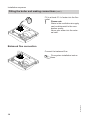
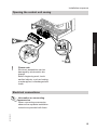
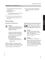
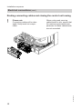
Installation and service
instructions
VIESMANN
for contractors
Vitodens 111-W
Type B1LA, 6.5 to 35.0 kW
Gas condensing storage combi boiler
Natural gas and LPG version
For applicability, see the last page
VITODENS 111-W
5618 689 UAE
3/2012
Please keep safe.
Safety instructions
Safety instructions
Please follow these safety instructions closely to prevent accidents and material losses.
Safety instructions explained
Danger
This symbol warns against the
risk of injury.
!
■ the Code of Practice of relevant trade
associations.
■ all current safety regulations as
defined by DIN, EN, DVGW, TRGI,
TRF, VDE and all locally applicable
standards.
Please note
This symbol warns against the
risk of material losses and environmental pollution.
If you smell gas
Target group
These instructions are exclusively
designed for qualified personnel.
■ Work on gas equipment must only be
carried out by a qualified gas fitter.
■ Work on electrical equipment must
only be carried out by a qualified electrician.
■ The system must be commissioned by
the system installer or a qualified person authorised by the installer.
Regulations
Observe the following when working on
this system
■ all legal instructions regarding the prevention of accidents,
■ all legal instructions regarding environmental protection,
2
Danger
Escaping gas can lead to explosions which may lead to serious
injury.
■ Do not smoke. Prevent naked
flames and sparks. Never
switch lights or electrical appliances ON or OFF.
■ Close the gas shut-off valve.
■ Open windows and doors.
■ Remove all people from the
danger zone.
■ Notify your gas or electricity
supplier from outside the building.
■ Shut off the electricity supply to
the building from a safe place
(outside the building).
If you smell flue gas
Danger
Flue gas can lead to life-threatening poisoning.
■ Shut down the heating system.
■ Ventilate the boiler room.
■ Close all doors in the living
space.
5618 689 UAE
Note
Details identified by the word "Note" contain additional information.
Safety instructions
Safety instructions (cont.)
Working on the system
■ When using gas as fuel, also close the
main gas shut-off valve and safeguard
against unauthorised reopening.
■ Isolate the system from the power supply and check that it is no longer 'live',
e.g. by removing a separate fuse or by
means of a main isolator.
■ Safeguard the system against unauthorised reconnection.
!
Please note
Electronic modules can be damaged by electrostatic discharges.
Touch earthed objects, such as
heating or water pipes, to discharge static loads.
Ancillary components, spare and
wearing parts
!
Please note
Spare and wearing parts that
have not been tested together
with the heating system can compromise its function. Installing
non-authorised components and
non-approved modifications or
conversions can compromise
safety and may invalidate our
warranty.
For replacements, use only original spare parts supplied or
approved by Viessmann.
Repair work
Please note
Repairing components that fulfil a
safety function can compromise
the safe operation of your heating
system.
Replace faulty components only
with original Viessmann spare
parts.
5618 689 UAE
!
3
Index
Index
Service instructions
Installation information
Product information..............................................................................................
Preparing for the boiler installation.......................................................................
6
7
Installation instructions
Installation sequence
Fitting the wall mounting bracket.......................................................................... 9
Fitting the boiler and making connections............................................................ 10
Opening the control unit casing............................................................................ 15
Electrical connections........................................................................................... 15
Service instructions
Commissioning, inspection, maintenance
Steps - commissioning, inspection and maintenance.......................................... 19
Further details regarding the individual steps....................................................... 20
Troubleshooting
Function sequence and possible faults................................................................ 38
Fault messages on the display............................................................................. 39
Repairs................................................................................................................. 43
Gas type conversion
Converting from LPG to natural gas .................................................................... 52
Control unit
Functions and operating conditions in weather-compensated mode................... 54
Parts lists
Ordering parts......................................................................................................
Overview of the assemblies.................................................................................
Casing assembly..................................................................................................
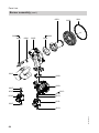
Heat cell assembly...............................................................................................
Burner assembly..................................................................................................
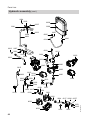
Hydraulic assembly..............................................................................................
Aqua plate assembly............................................................................................
Control unit assembly...........................................................................................
Cylinder assembly................................................................................................
Miscellaneous assembly......................................................................................
4
58
59
60
61
63
65
67
68
70
71
5618 689 UAE
Designs
Connection and wiring diagram............................................................................ 56
Index
Index (cont.)
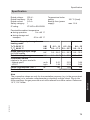
Specification....................................................................................................... 73
Certificates
Declaration of conformity...................................................................................... 74
5618 689 UAE
Keyword index.................................................................................................... 75
5
Installation information
Product information
Vitodens 111-W, type B1LA
Preset for operation with natural gas.
Conversion to LPG P requires a gas conversion kit.
Conversion for other countries
5618 689 UAE
The Vitodens 111-W should generally
only be delivered to those countries
specified on the type plate. For deliveries
to alternative countries, an approved
contractor must arrange individual
approval on his own initiative and in
accordance with the law of the country in
question.
6
Installation information
Preparing for the boiler installation
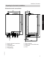
Dimensions and connections
166
945
1003
900
740
Service
497
A
BC
D
E
Area for electrical connections
Heating flow
Condensate drain
Heating return
Filling/draining
35
480
F
G
H
K
Gas connection
Safety valve (on the DHW side)
Cold water
DHW
5618 689 UAE
A
B
C
D
E
F GH K
7
Installation information
Preparing for the boiler installation (cont.)
Preparing the connections
Note
This boiler (IP rating: IP X4D) is
approved for installation in wet rooms
inside safety zone 1 in accordance with
DIN VDE 0100, providing the occurrence
of hosed water can be ruled out.
Observe the requirements of DIN VDE
0100.
1. Prepare the water connections. Flush
the heating system.
2. Prepare the gas connection.
5618 689 UAE
3. Prepare the electrical connections.
■ Power cable NYM-J 3 x 1.5 mm2.
■ Accessory cables:
NYM-O two-core min. 0.5 mm2.
8
Installation sequence
250
Installation
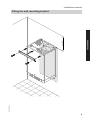
Fitting the wall mounting bracket
5618 689 UAE
Ø10
9
Installation sequence
Fitting the boiler and making connections
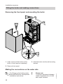
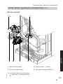
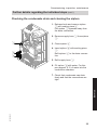
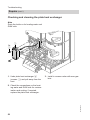
Removing the front panel and mounting the boiler
3.
2.
1.
2x
1. Undo screws at the bottom of the
boiler; do not remove completely.
3. Hook the boiler into the wall mounting
bracket.
2. Remove front panel.
For fittings on the heating water
side and DHW side, see separate
installation instructions.
10
!
Please note
To prevent equipment damage,
install all pipework free of load
and torque stresses.
5618 689 UAE
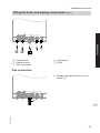
Making the connections on the water side
Installation sequence
Fitting the boiler and making connections (cont.)
B
C
D E
Installation
A
z z
¨
A Heating flow
B Heating return
C Gas connection
D Cold water
E DHW
Gas connection
1. Connect gas shut-off valve to connection A.
5618 689 UAE
A
11
Installation sequence
Fitting the boiler and making connections (cont.)
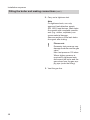
2. Carry out a tightness test.
Note
For tightness tests, use only
approved leak detection agents
(EN 14291) and devices. Leak detection agents with unsuitable constituents (e.g. nitrites, sulphides) can
cause material damage.
Remove residues of the leak detection agent after testing.
!
Please note
Excessive test pressure may
damage the boiler and the gas
valve.
Max. test pressure 150 mbar.
Where higher pressure is
required for tightness tests,
disconnect the boiler and the
gas valves from the gas supply pipe (undo the fitting).
5618 689 UAE
3. Vent the gas line.
12
Installation sequence
Fitting the boiler and making connections (cont.)
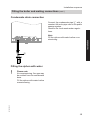
Condensate drain connection
Note
Fill the siphon with water before commissioning.
A
Filling the siphon with water
Please note
At commissioning, flue gas may
be emitted from the condensate
drain.
Fill the siphon with water before
commissioning.
5618 689 UAE
!
13
Installation
Connect the condensate pipe A with a
constant fall and a pipe vent to the public
sewage system.
Observe the local waste water regulations.
Installation sequence
Fitting the boiler and making connections (cont.)
Fill in at least 0.3 l of water into the flue
outlet.
Please note
Water in the ventilation air supply
can be detrimental to the combustion quality.
Never pour water into the external vent.
!
Balanced flue connection
Connect the balanced flue.
5618 689 UAE
Flue system installation instructions.
14
Installation sequence
Opening the control unit casing
2.
Installation
3.
4x
2x
!
1.
Please note
Electronic assemblies can be
damaged by electrostatic discharge.
Before beginning work, touch
earthed objects, such as heating
or water pipes, to discharge static
loads.
Electrical connections
5618 689 UAE
Information on connecting
accessories
When connecting accessories
observe the separate installation
instructions provided with them.
15
Installation sequence
Electrical connections (cont.)
X21
X7
D
X1
X20
?LN 1 LN
C
E F
4 3 2 1
OT
A B
A Only for weather-compensated
mode:
Outside temperature sensor (accessory)
B OpenTherm device
Remove jumper D when making
this connection.
C Connecting cable (accessory)
D Jumper
E Power supply (230 V, 50 Hz).
See page 17.
F Vitotrol 100
Remove jumper D when making
this connection.
Separate installation instructions
Accessory connection
When connecting a Vitotrol 100 or an
OpenTherm remote control, remove the
jumper across L and 1.
16
Outside temperature sensor (accessory)
1. Fit outside temperature sensor.
Installation site:
■ North or north-westerly wall, 2 to
2.5 m above ground level; in multi
storey buildings, in the upper half of
the second floor
■ Not above windows, doors or ventilation outlets
5618 689 UAE
Accessory installation instructions
Installation sequence
Electrical connections (cont.)
■ Not immediately below balconies
or gutters
■ Never render over
■ Connection:
2-core lead, length max. 35 m with
a cross-section of 1.5 mm2
3. Connect the outside temperature
sensor to terminals 3 and 4 (see
page 16).
Power supply
Regulations and Directives
Danger
Incorrectly executed electrical
installations may result in injuries
through electric shock and to
appliance damage.
Connect the power supply and
implement all safety measures
(e.g. RCD circuit) in accordance
with the following regulations:
■ IEC 60364-4-41
■ VDE regulations
■ Connection requirements
specified by your local power
supply utility
Danger
Incorrect core allocation can
result in serious injury and damage to the appliance.
Take care not to interchange
wires "L1" and "N".
Danger
The absence of component
earthing in the system can lead to
serious injury from electrical current if an electrical fault occurs.
Connect the appliance and pipework to the equipotential bonding
of the building in question.
5618 689 UAE
Install an isolator in the power cable
which simultaneously separates all nonearthed conductors from the mains with
contact separation of at least 3 mm.
We additionally recommend installing an
AC/DC-sensitive RCD (RCD class B
) for DC (fault) currents that can
occur with energy efficient equipment.
Protect the power cable with max. 16 A.
17
Installation
2. Plug the power cable supplied with
the outside temperature sensor into
slot "X21".
Installation sequence
Electrical connections (cont.)
Routing connecting cables and closing the control unit casing
!
Please note
Connecting cables will be damaged if they touch hot components.
When routing and securing
cables/leads on site, ensure that
the maximum permissible temperatures for these cables/leads
are not exceeded.
2.
5618 689 UAE
1.
18
Commissioning, inspection, maintenance
Steps - commissioning, inspection and maintenance
For further information regarding the individual steps, see the page indicated
Commissioning steps
Inspection steps
Maintenance steps
5618 689 UAE
•
•
•
•
•
•
•
•
•
•
•
•
Page
1. Filling the heating system.............................................. 20
2. Venting the boiler by flushing....................................... 22
3. Changing to operation with LPG................................... 23
4. Matching the burner output to the flue system........... 23
5. Reducing the max. heating output................................ 24
6. Checking the CO2 content............................................. 26
•
•
•
•
7. Burner removal .............................................................. 29
•
•
•
•
•
•
9. Checking and adjusting electrode................................ 31
•
•
•
•
12. Burner installation ......................................................... 34
•
•
14. Checking the function of safety valves
•
•
•
•
•
•
16. Checking flue system for unrestricted flow and
tightness
•
•
•
•
•
•
17. Checking firm seating of electrical connections
•
•
•
8. Checking the burner gasket and burner gauze
assembly......................................................................... 30
10. Cleaning the heat exchanger......................................... 32
11. Checking the condensate drain and cleaning the
siphon.............................................................................. 33
13. Checking the diaphragm expansion vessel and
system pressure............................................................. 36
Service
15. Checking all connections on the heating water side
and DHW side for leaks
18. Checking gas equipment for tightness at operating
pressure .......................................................................... 36
19. Fitting the front panel..................................................... 37
20. Instructing the system user........................................... 37
19
Commissioning, inspection, maintenance
Further details regarding the individual steps
Filling the heating system
!
Please note
Unsuitable fill water increases
the level of deposits and corrosion and may lead to boiler damage.
■ Thoroughly flush the entire
heating system prior to filling it
with water.
■ Only use fill water of potable
quality.
■ Soften fill water harder than
16.8 °dH (3.0 mmol/l).
■ An antifreeze additive suitable
for heating systems can be
added to the fill water.
1. Close the gas shut-off valve.
2. Switch ON power and wait until the
display shows the boiler water temperature.
3. Turn rotary selector "rt" fully anticlockwise, until the display shows
"SERV".
Within 2 s return the rotary selector to
the r.h. control range.
The display shows "r" and "w".
Filling is active.
This function will end automatically
after 20 min or after the ON/OFF
switch has been turned off.
5618 689 UAE
r
20
Commissioning, inspection, maintenance
Further details regarding the individual steps (cont.)
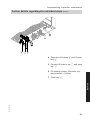
A CB
4. Open shut-off valves A and (if installed) B.
5. Connect fill hose to tap C and open
tap C.
6. Fill heating system. (Minimum system pressure > 0.8 bar).
5618 689 UAE
Service
7. Close tap C.
21
Commissioning, inspection, maintenance
Further details regarding the individual steps (cont.)
Venting the boiler by flushing
B
A
1. Close the shut-off valves on the heating water side.
4. Close taps A and B, open the shutoff valves on the heating water side.
3. Open taps A and B and vent at
mains pressure, until no sound of
escaping air can be heard.
22
5618 689 UAE
2. Connect the drain hose between top
tap B and a drain.
Commissioning, inspection, maintenance
Further details regarding the individual steps (cont.)
Changing to operation with LPG
In the delivered condition, the boiler is
set up for operation with natural gas. For
operation with LPG, change the gas nozzle and convert the gas type in the control unit.
Separate installation instructions.
Changing from LPG to natural gas - see
page 52.
Matching the burner output to the flue system
To match the burner output to the system's flue pipe length, a correction factor
can be set.
1. Switch on the ON/OFF switch.
2. Turn both rotary selectors "tw" and
"tr" simultaneously to their respective central positions.
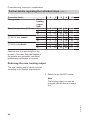
"SERV" appears on the display.
3. Refer to the following table for the
correction factor required for the connected flue system.
4. Within 2 s, turn rotary selector "tw"
into the top left range.
The display shows "r", "w", "A",
and the selected correction factor
flashes.
In the delivered condition, factor 0
has been set.
5. Within 15 s, set rotary selector
"tr" to the required correction factor.
5618 689 UAE
r
6. The set correction factor is saved
when the value stops flashing, and
the control unit returns to standard
mode.
23
Service
r
Commissioning, inspection, maintenance
Further details regarding the individual steps (cont.)
Correction factor
Flue system
Open flue operation 7 60 mm
Balanced flue operation
7 60/100 mm coaxial
Balanced flue operation
7 60/60 mm parallel
Rated
heating
output
(kW)
19
26
35
19
26
35
19
26
35
1
2
3
4
5
Max. run length (m)
4
2
5
2
1
3
4
2
5
10
16
22
8 13.5 18.5
12
18
23
6
10
13
4
7
10
6
9
12
10
16
22
8 13.5 18.5
12
18
23
—
22
—
16
12
14
27
22
—
6
—
25
—
19
13.5
17
32
25
—
Observe max. flue pipe lengths in the
pricelist. If the max. flue pipe lengths in
the pricelist are exceeded, calculated
performance verification is required.
Reducing the max. heating output
The max. heating output can be reduced
according to the system requirements.
1. Switch on the ON/OFF switch.
5618 689 UAE
Note
The heating output can only be
changed with the burner in operation.
24
Commissioning, inspection, maintenance
Further details regarding the individual steps (cont.)
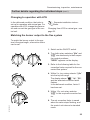
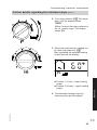
2. Turn rotary selector "tr" fully clockwise, until the display shows
"SERV".
Within 2 s return the rotary selector to
the r.h. control range. The display
shows "A".
r
3. Select the required max. heating output with rotary selector "tr".
Bars indicating the selected heating
output flash on the display.
°C
60
A
Service
■ Position 1 (1 bar) = lower heating
output.
■ Position 6 (5 bars) = upper heating
output.
5618 689 UAE
4. Test selected heating output by
measuring the gas throughput.
25
Commissioning, inspection, maintenance
Further details regarding the individual steps (cont.)
5. Transfer selected heating output:
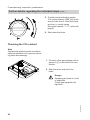
Turn rotary selector "tw" fully clockwise for less than 2 s and then back
into the r.h. control range.
During the transfer, "-.-.-". will be displayed.
6. Shut down the boiler.
Checking the CO2 content
Note
Operate the appliance with uncontaminated combustion air to prevent operating faults and damage.
01. Connect a flue gas analyser at flue
gas port A on the boiler flue connection.
02. Start the boiler and check for
leaks.
Danger
Escaping gas leads to a risk
of explosion.
Check gas equipment for
tightness.
5618 689 UAE
A
26
Commissioning, inspection, maintenance
Further details regarding the individual steps (cont.)
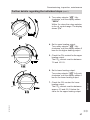
03. Turn rotary selector "tr" fully
clockwise, until the display shows
"SERV".
Within 2 s return the rotary selector
to the r.h. control range. The display
shows "A".
r
04. Set to upper heating output:
Turn rotary selector "tr" fully
clockwise, until the display shows 5
bars for the higher heating output.
05. Check the CO2 content for the upper
heating output.
The CO2 content must be between
7.0 and 10.5 %.
5618 689 UAE
07. Check the CO2 content for lower
heating output.
The CO2 content must be between
approx. 0.3 and 0.9 % below the
value for the upper heating output.
27
Service
06. Set to lower heating output:
Turn rotary selector "tr" fully anticlockwise, until the display shows 1
bar for the lower heating output.
Commissioning, inspection, maintenance
Further details regarding the individual steps (cont.)
08. ■ If the CO2 content is within the
given range, continue with point
10.
■ If the CO2 content is outside the
given range, check the flue gas/
ventilation air system for tightness; remedy any leaks.
Replace gas train if required.
09. Check the CO2 content for upper
and lower heating output again.
10. Shut down the boiler, remove the
flue gas analyser and cap flue gas
port A.
5618 689 UAE
11. Turn both rotary selectors "tw" and
"rt" to their original positions.
28
Commissioning, inspection, maintenance
Further details regarding the individual steps (cont.)
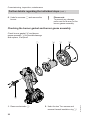
Burner removal
F4x
5618 689 UAE
B
A
Service
C
E
D
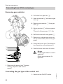
1. Switch off the power.
4. Push grommet D down.
2. Shut off the gas supply.
5. Undo gas supply pipe fitting E.
3. Pull power cables from fan motor
A, gas valve B and electrodes
C.
29
Commissioning, inspection, maintenance
Further details regarding the individual steps (cont.)
6. Undo four screws F and remove the
burner.
!
Please note
To prevent any damage,
never rest the burner on the
burner gauze assembly.
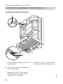
Checking the burner gasket and burner gauze assembly
Check burner gasket A and burner
gauze assembly D for possible damage
and replace, if required.
E
D
C
A
2x
1. Remove electrode B.
30
2. Undo the two Torx screws and
remove thermal insulation ring C.
5618 689 UAE
B
Commissioning, inspection, maintenance
Further details regarding the individual steps (cont.)
3. Undo two Torx screws and remove
burner gauze assembly D with its
gasket E.
4. Insert a new gasket E and a new
burner gauze assembly D and
secure.
Fixing screw torque: 3.5 Nm.
5. Mount thermal insulation ring C.
Fixing screw torque: 3.5 Nm.
6. Fit electrode B.
Fixing screw torque: 4.5 Nm.
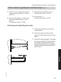
Checking and adjusting electrode
1. Check the electrode for wear and
contamination.
2. Clean the electrode with a small
brush (not with a wire brush) or emery
paper.
8+2
3. Check the electrode gaps. If the gaps
are not as specified or the electrode
is damaged, replace and align the
electrode together with a new gasket.
Tighten the electrode fixing screws
with 4.5 Nm.
5618 689 UAE
Service
4+0,5
31
Commissioning, inspection, maintenance
Further details regarding the individual steps (cont.)
Cleaning the heat exchanger
1.
!
Please note
Scratches on parts that are in
contact with flue gas can lead
to corrosion.
Never use brushes to clean
the heat exchanger.
Use a vacuum cleaner to remove residues from heat exchanger A inside
the combustion chamber.
A
2. If required, spray slightly acidic,
chloride-free cleaning agents based
on phosphoric acid onto heat
exchanger A and let the solution
soak in for at least 20 min.
5618 689 UAE
3. Thoroughly flush heat exchanger A
with water.
32
Commissioning, inspection, maintenance
Further details regarding the individual steps (cont.)
Checking the condensate drain and cleaning the siphon
1. Release hook and remove siphon
A with sealing piece B.
Pull siphon A upwards away from
the drain connection.
2. Remove supply hose C from siphon
A.
C
3. Clean siphon A.
A
4. Insert siphon A with sealing piece
B.
Refit siphon C to the drain connection.
B
5. Refit supply hose C.
6. Fill siphon A with water. For this,
pour approx. 0.3 l of water into the
combustion chamber.
5618 689 UAE
Service
7. Check that condensate can drain
freely and that the connections are
tight.
33
Commissioning, inspection, maintenance
Further details regarding the individual steps (cont.)
Burner installation
A4x
E
D
C
1. Mount burner and secure with four
screws A.
4. Fit electrical cables to fan motor D,
gas valve E and ignition unit F.
2. Insert new gasket and tighten the fittings on gas supply pipe B.
5. Reopen gas supply and switch ON
power supply.
3. Tighten four screws A diagonally
with 8.5 Nm.
34
5618 689 UAE
F
B
Commissioning, inspection, maintenance
Further details regarding the individual steps (cont.)
6. Check the gas connections for tightness.
7. Push grommet C up again.
Danger
Escaping gas leads to a risk of
explosion.
Check all fittings for gas tightness.
Please note
The use of leak detection
spray can result in incorrect
function.
Leak detection spray must not
reach electrical contacts or
seal diaphragm openings on
the gas valve.
5618 689 UAE
Service
!
35
Commissioning, inspection, maintenance
Further details regarding the individual steps (cont.)
Checking the diaphragm expansion vessel and system pressure
Carry out this check with a cold system.
1. Drain the system, until the pressure
gauge indicates "0".
2. If the pre-charge pressure of the diaphragm expansion vessel is lower
than the static system pressure, top
up with nitrogen until the pre-charge
pressure is raised by 0.1 to 0.2 bar.
3. Top up with water until the charge
pressure of the cooled system is at
least 1.0 bar and 0.1 to 0.2 bar higher
than the pre-charge pressure of the
diaphragm expansion vessel.
Permiss. operating pressure: 3 bar
A
A Test port
Checking gas equipment for tightness at operating pressure
!
Please note
The use of leak detection spray
can result in incorrect function.
Leak detection spray must not
reach electrical contacts or seal
diaphragm openings on the gas
valve.
5618 689 UAE
Danger
Escaping gas leads to a risk of
explosion.
Check gas equipment for tightness.
36
Commissioning, inspection, maintenance
Further details regarding the individual steps (cont.)
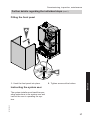
Fitting the front panel
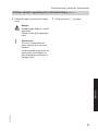
1.
2.
2x
2. Tighten screws at the bottom.
Service
1. Hook the front panel into place.
Instructing the system user
5618 689 UAE
The system installer must hand the operating instructions to the system user and
instruct the user in operating the system.
37
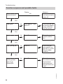
Troubleshooting
Function sequence and possible faults
Display
No
Control unit issues
a heat demand
Measure
Increase set value
and ensure heat is
drawn off
Yes
Fan starts
No
After approx. 1 min
fault F9
Check the fan, fan
connecting cables,
power at the fan
and fan control
No
Fault F4
Check the ignition
module connection
No
Fault F4
Check the gas
train (control voltage 230 V); check
the gas supply
pressure
No
Fault F4
Check the ionisation current, check
the electrode
adjustment and
the gas line for airlocks.
Yes
Ignition
Yes
Gas train opens
Yes
5618 689 UAE
Ionisation current
builds (greater
than 2 µA)
Symbol A
38
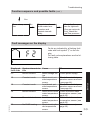
Troubleshooting
Function sequence and possible faults (cont.)
Yes
Burner in operation
No
Stops below the set
boiler water temperature and
restarts immediately
Check the flue system for tightness
(flue gas recirculation), check the
gas flow pressure
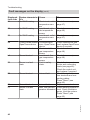
Fault messages on the display
Displayed
fault code
0C
10
18
30
5618 689 UAE
38
50
System characteris- Cause
tics
Burner blocked
Mains voltage too
low
Constant mode
Short circuit, outside temperature
sensor
Constant mode
Lead break, outside temperature
sensor
Burner blocked
Short circuit, boiler
water temperature
sensor
Burner blocked
Lead break, boiler
water temperature
sensor
No DHW heating
Short circuit, cylinder temperature
sensor
Measures
Check power supply.
Check the outside temperature sensor and lead
(see page 44).
Check the outside temperature sensor and lead
(see page 44).
Check the boiler water
temperature sensor (see
page 45).
Check the boiler water
temperature sensor (see
page 45).
Check the sensor (see
page 46).
39
Service
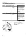
f2
Faults are indicated by a flashing fault
code with fault symbol "U" on the display.
For fault code explanations see the following table.
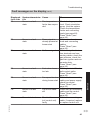
Troubleshooting
Fault messages on the display (cont.)
Displayed
fault code
51
58
59
A9
b0
b8
E3
System characteris- Cause
tics
No DHW heating
Short circuit, outlet
temperature sensor
No DHW heating
Lead break, cylinder temperature
sensor
No DHW heating
Lead break, outlet
temperature sensor
Control mode without Communication
OpenTherm device
error, OpenTherm
device
Burner blocked
Short circuit, flue
gas temperature
sensor
Burner blocked
Lead break, flue
gas temperature
sensor
Burner in a fault
Fault in safety
state
chain.
Burner blocked
F0
F1
Burner blocked
Burner in a fault
state
Check the sensor (see
page 47).
Check the sensor (see
page 46).
Check the sensor (see
page 47).
Check connections and
lead; replace OpenTherm
device if required.
Check the sensor (see
page 49).
Check the sensor (see
page 49).
Check the temperature
limiter and connecting
leads (see page 48).
Check the control unit,
and replace if required.
Internal fault
Check the ignition/ionisation electrode and connecting cables.
Press "Reset" (see
page 42).
Internal fault
Replace control unit.
Max. flue gas tem- Check heating system fill
perature exceeded level. Check circulation
pump. Vent the system.
Press "Reset" (see
page 42).
5618 689 UAE
E5
Measures
40
Troubleshooting
Fault messages on the display (cont.)
F3
Burner in a fault
state
Flame signal is
already present at
burner start
F4
Burner in a fault
state
No flame signal
F8
Burner in a fault
state
Fuel valve closes
too late
F9
Burner in a fault
state
Fan speed too low
during burner start
FA
Burner in a fault
state
Fan not at standstill
FC
Burner blocked
Electrical fan control (control unit)
faulty
Measures
Check heating system fill
level. Check circulation
pump. Vent the system.
Check the temperature
limiter and connecting
leads (see page 48).
Press "Reset" (see
page 42).
Check ionisation electrode and connecting
cables.
Press "Reset" (see
page 42).
Check the ignition/ionisation electrode and connecting cables, check the
gas pressure, check the
gas train, ignition and condensate drain.
Press "Reset" (see
page 42).
Check gas train. Check
both control paths.
Press "Reset" (see
page 42).
Check fan, fan connecting
cables and power supply;
check fan control.
Press "Reset" (see
page 42).
Check fan, fan connecting
cables and fan control.
Press "Reset" (see
page 42).
Check fan connecting
cable; if required, replace
or replace control unit.
41
Service
System characteris- Cause
tics
Burner in a fault
The temperature
state
limiter has responded
5618 689 UAE
Displayed
fault code
F2
Troubleshooting
Fault messages on the display (cont.)
Displayed
fault code
Fd
FF
System characteris- Cause
tics
Burner blocked
Fault, burner control unit
Burner blocked
Fault, burner control unit
Measures
Check ignition electrodes
and connecting cables.
Check whether a strong
interference (EMC) field
exists near the appliance.
Press "Reset" (see
page 42).
Replace control unit if
fault persists.
Check ignition electrodes
and connecting cables.
Check whether a strong
interference (EMC) field
exists near the appliance.
Press "Reset" (see
page 42).
Replace control unit if
fault persists.
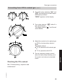
Press reset
Turn rotary selector "rt" to "U
RESET", until "SERV" is shown.
Within 2 s return the rotary selector to the
control range.
5618 689 UAE
r
42
Troubleshooting
Repairs
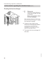
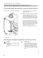
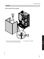
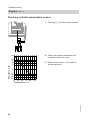
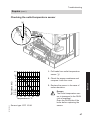
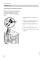
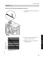
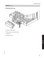
Removing the front panel
2.
1.
2x
Service
2. Remove front panel.
5618 689 UAE
1. Undo screws at the bottom of the
boiler; do not remove completely.
43
Troubleshooting
Repairs (cont.)
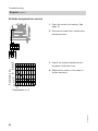
Outside temperature sensor
1. Open the control unit casing. See
page 15.
X21
X7
X20
2. Disconnect leads from outside temperature sensor.
4 3 2 1
20
3. Check the sensor resistance and
compare it with the curve.
4. Replace the sensor in the case of
severe deviation.
10
8
6
4
-15 -5 0 10 20 30
-10
Temperature in °C
5618 689 UAE
Resistance in kΩ
100
80
60
40
44
Troubleshooting
Repairs (cont.)
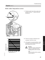
Boiler water temperature sensor
1. Pull the leads from boiler water temperature sensor A and check the
resistance.
A
5618 689 UAE
10
8
6
4
2
1
0.8
0.6
0.4
10 30 50 70 90 110
Temperature in °C
2. Check the sensor resistance and
compare it with the curve.
3. In the case of severe deviation, drain
the boiler on the heating water side
and replace the sensor.
Danger
The boiler water temperature
sensor is immersed in the
heating water (risk of scalding).
Drain the boiler before replacing the sensor.
45
Service
Resistance in kΩ
20
Troubleshooting
Repairs (cont.)
Checking cylinder temperature sensor
1. Pull plug % from the cable harness.
X21
X7
X20
5
10
8
6
4
2. Check the sensor resistance and
compare it with the curve.
3. Replace the sensor in the case of
severe deviation.
2
1
0.8
0.6
0.4
10 30 50 70 90 110
Temperature in °C
5618 689 UAE
Resistance in kΩ
20
46
Troubleshooting
Repairs (cont.)
Checking the outlet temperature sensor
A
5618 689 UAE
10
8
6
4
2
1
0.8
0.6
0.4
10 30 50 70 90 110
Temperature in °C
Sensor type: NTC 10 kΩ
1. Pull leads from outlet temperature
sensor A.
2. Check the sensor resistance and
compare it with the curve.
Service
Resistance in kΩ
20
3. Replace the sensor in the case of
severe deviation.
Danger
The outlet temperature sensor is immersed in the DHW
(risk of scalding).
Drain the DHW side of the
boiler before replacing the
sensor.
47
Troubleshooting
Repairs (cont.)
Checking the temperature limiter
If the burner control unit cannot be reset
after a fault shutdown, although the
boiler water temperature is below
approx. 95 °C, check the temperature
limiter.
1. Pull the leads from temperature limiter A.
A
2. Check the continuity of the temperature limiter with a multimeter.
3. Remove the faulty temperature limiter.
4. Install a new temperature limiter.
5618 689 UAE
5. Press "Reset" at the control unit (see
page 42).
48
Troubleshooting
Repairs (cont.)
Checking the flue gas temperature sensor
1. Pull leads from flue gas temperature
sensor A.
A
5618 689 UAE
10
8
6
4
2. Check the sensor resistance and
compare it with the curve.
3. Replace the sensor in the case of
severe deviation.
Service
Resistance in kΩ
20
2
1
0.8
0.6
0.4
10 30 50 70 90 110
Temperature in °C
49
Troubleshooting
Repairs (cont.)
Checking and cleaning the plate heat exchanger
Note
Drain the boiler on its heating water and
DHW side.
2x
B
A
1. Undo plate heat exchanger A
(screws B) and pull away from the
front.
3. Install in reverse order with new gaskets.
5618 689 UAE
2. Check the connections on the heating water and DHW side for contamination and scaling; if required,
replace the plate heat exchanger.
50
Troubleshooting
Repairs (cont.)
Checking the fuse
F4
1. Switch off the power.
2. Open control unit casing (see
page 15).
5618 689 UAE
Service
3. Check fuse F4.
51
Gas type conversion
Converting from LPG to natural gas
Removing gas restrictor
2. Pull cable from gas train A.
3. Undo two screws B and remove gas
train A.
4. Remove gas restrictor C from gas
train A.
5. Mount gas train A with new gasket
D.
Torque for fixing screws B: 3 Nm.
6. Refit the burner with new gasket E.
7. Remove or void gas type sticker on
the top of the boiler (next to the type
plate).
8. Fitting the burner (see "Commissioning, inspection and maintenance")
C
D
B
A
9. Start the boiler and check for leaks.
Danger
Escaping gas leads to a risk of
explosion.
Check gas equipment for
tightness.
E
1. Removing the burner (see "Commissioning, inspection and maintenance")
1. Switch on the ON/OFF switch.
52
5618 689 UAE
Converting the gas type at the control unit
Gas type conversion
Converting from LPG to natural gas (cont.)
2. Turn both rotary selectors "tw" and
"tr" simultaneously to their respective central positions.
"SERV" appears on the display.
r
3. Turn rotary selector "tr" within 2 s
fully anticlockwise.
The display shows "A" and the set
value flashes.
r
5. The set operating mode is saved
when the value stops flashing, and
the control unit returns to standard
mode.
Checking the CO2 content
5618 689 UAE
See "Commissioning, inspection and
maintenance".
53
Service
4. Adjust the control unit to natural gas
or LPG by turning rotary selector
"tw".
The display shows:
■ "0" for operation with natural gas
or
■ "1" for operation with LPG.
Control unit
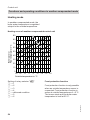
Functions and operating conditions in weather-compensated mode
Heating mode
In weather-compensated mode, the
boiler water temperature is regulated
subject to the outside temperature.
Heating curve of weather-compensated control unit
90
G
80
F
Boiler water or
Flow temperature in °C
70
E
D
60
C
50
B
40
A
30
20
10
0
20 15
10
5
0
-5
-10 -15 -20
Outside temperature in °C
Frost protection function
Frost protection function is only possible
when an outside temperature sensor is
connected. Frost protection function is
active at outside temperatures of < 5°C.
The burner starts and the boiler water
temperature is held at 20 °C.
5618 689 UAE
Setting of rotary selector "tr"
A =1
B =2
C =3
D =4
E = delivered condition
F =5
G =6
54
Control unit
Functions and operating conditions in… (cont.)
DHW heating
Heating the DHW primary store from
cold
The heating circuit pump is switched on
and the 3-way diverter valve will be
changed over, if the cylinder temperature sensor captures a temperature
lower than the default set value.
■ The cylinder primary pump is switched
on if the boiler water temperature ≥ set
DHW temperature.
■ The burner is switched on if the boiler
water temperature ≤ set DHW temperature, and the cylinder primary pump
is switched on when the required boiler
water temperature is reached.
The primary store is heated up to the set
DHW temperature. Heating stops when
the specified temperature has been
reached at the cylinder temperature sensor.
After heating, the cylinder primary pump
and the 3-way diverter valve remain on
for a further 30 s.
■ The cylinder primary pump is switched
on if the boiler water temperature ≥ set
DHW temperature.
■ The burner is switched on if the boiler
water temperature ≤ set DHW temperature, and the cylinder primary pump
is switched on when the required boiler
water temperature is reached.
DHW is regulated to the set temperature
via the outlet temperature sensor.
The primary store continues to be heated
up after the draw off process has terminated, until the set DHW temperature
has been reached at the cylinder temperature sensor.
The cylinder primary pump and the 3way diverter valve remain on for a further
30 s.
Reheating when DHW is drawn off
5618 689 UAE
Service
When DHW is drawn off, cold water
enters at the bottom of the primary
store.
The heating circuit pump is switched on
and the 3-way diverter valve is changed
over, if the cylinder temperature sensor
recognises a temperature lower than the
set value.
55
Designs
A
B
56
Stepper motor diverter valve
Ignition/ionisation
5618 689 UAE
H
G
F
E
A
D
C
B
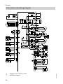
Connection and wiring diagram
Designs
Connection and wiring diagram (cont.)
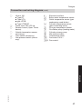
C
D
E
F
X ...
§
$
Electrical interface
Boiler water temperature sensor
Outlet temperature sensor (gas
condensing combi boiler)
Cylinder temperature sensor
%
(gas condensing boiler)
Flue gas temperature sensor
aG
Circulation pump (heating water)
sÖ
Cylinder primary pump
sA
Gas solenoid valve
dG
Temperature limiter
fJ
a-Ö Fan motor 230 V~
a-ÖA Fan control
5618 689 UAE
Service
G
H
Vitotrol 100
■ Type RT
■ Type UTA
■ type UTDB
■ Type UTDB-RF
Power input 230 V/50 Hz
Remote control (Open Therm
device)
Outside temperature sensor
(accessory)
Time switch (accessory)
Gas pressure switch (accessory)
57
Parts lists
Ordering parts
Standard parts are available from your
local supplier.
5618 689 UAE
The following information is required:
■ Serial no. (see type plate A)
■ Assembly (from this parts list)
■ Position number of the individual part
within the assembly (from this parts
list)
58
Parts lists
Overview of the assemblies
A
B
C
E
Service
D
5618 689 UAE
F
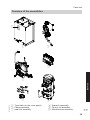
A Type plate (on the cover panel)
B Casing assembly
C Heat cell assembly
G
D Hydraulic assembly
E Control unit assembly
F Miscellaneous assembly
59
Parts lists
Overview of the assemblies (cont.)
G Cylinder assembly
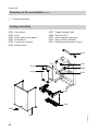
Casing assembly
0001
0002
0003
0004
0005
0006
Front panel
Logo
Cover panel with gasket
Profiled seal
Control unit support
Safety guard
0007
0008
0012
0013
0014
Toggle fastener (set)
Pipe clip Ø 18
Air box gasket, gas pipe
Wall mounting bracket
Diaphragm grommets (5 pce)
0013
0004
0014
0007
0008
0003
0012
0005
0006
0001
60
5618 689 UAE
0002
Parts lists
Heat cell assembly
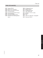
Gasket DN 60
Boiler flue connection
Boiler flue connection plug
Flue gas gasket
Flue gas temperature sensor
Heat exchanger
Thermal insulation block
Moulded hose heating water
return
0009
0010
0013
0015
0016
0019
0020
0021
0023
Condensate hose
Splash siphon
Condensate hose
Gas supply pipe
Gasket 17 x 24 x 2 (set)
Burner
Tee
Hose 19 x 600 mm, corrugated
Hose clip DN 25
5618 689 UAE
Service
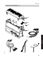
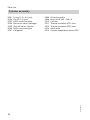
0001
0002
0003
0004
0005
0006
0007
0008
61
Parts lists
Heat cell assembly (cont.)
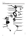
0005
0001
0002
0001
0003
0023
0003
0004
0008
0006
0023
0007
0009
0019
0010
0013
0016
0020
0015
0016
0023
5618 689 UAE
0021
62
Parts lists
Burner assembly
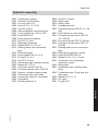
Burner gasket
Thermal insulation ring
Cylinder burner gauze assembly
Burner gauze assembly gasket
Burner door
Ionisation electrode gasket
Ignition and ionisation electrode
Burner door flange gasket
0009
0010
0012
0013
0014
0015
0016
Radial fan
Gas valve
Venturi extension
Gaskets (set)
Conversion kit G31
Gasket set G27
Conversion kit G2.350/G27
5618 689 UAE
Service
0001
0002
0003
0004
0005
0006
0007
0008
63
Parts lists
Burner assembly (cont.)
0003
0006
0007
0012
0015
0015
0016
0015
0002
0001
0003
0006
0005
0004
0008
0009
0013
0014
0013
0010
5618 689 UAE
0013
64
Parts lists
Hydraulic assembly
0001
0002
0003
0004
0005
0006
0007
0008
0009
0010
0011
0012
0013
0028
0029
0030
0031
0032
0033
0034
0035
0036
0037
0038
0039
0040
0041
0042
0043
0044
0045
0046
0051
Clip Ø 10 (5 pce)
Return pipe
Safety valve
Condensate hose
Circulation pump UPS 60 (19 - 26
kW)
Quick-action air vent valve
Circulation pump motor UPS 60
(19 - 26 kW)
Circulation pump UPS 70 (35 kW)
Circulation pump motor UPS 70
(35 kW)
Heating water return connection
pipe
Diaphragm expansion vessel
Hose clip Ø 220-240 x 9
Gasket A 10 x 15 x 1.5 (set)
Connection line; diaphragm
expansion vessel
Aqua-plate
Connection pipe, heating water
filling
Connection pipe, filling loop, potable water
Gasket A 6 x 11 x 1
Fill valve
Plug Ø 8/10
5618 689 UAE
Service
0014
0015
0017
0018
0019
0020
0021
0022
0023
0024
0025
0026
0027
Temperature sensor
Thermal circuit breaker
Air vent valve G ⅜
Hose Ø 10 x 1.5 x 750
Clip Ø 8 (5 pce)
Heat exchanger connection pipe
O-ring gasket set 17.86 x 2.62
Hose clip DN 25
Hose connector adaptor
Clip Ø 18 (5 pce)
Diaphragm grommet
Gasket set A 17 x 24 x 2
Heating water flow connection
pipe
Pressure gauge
O-ring gasket set 9.6 x 2.4
O-ring 14.3 x 2.4
Clip Ø 15 (5 pce)
Connection pipe, circulation pump
Gasket 23 x 30 x 2
Circulation pump VIUP-30
Circulation pump motor VIUP-30
Support, cylinder primary pump
Connection pipe, cold water
Connection manifold, cold water
Flat gasket
Round gasket 8 x 2
65
Parts lists
Hydraulic assembly (cont.)
0004
0003
0038
0005
0001
0039
0002
0008
0027
0005
0006
0040
0041
0012 0007
0010
0029
0009
0011
0030
0035
0008
0013
0031
0010
0042
0015
0028
0043
0045
0032
0015
0034
0015
0046
0020
0028
0036
0012
0028
0044
0045 0017
0014
0020
0019
0020
0018
0037
0021
0020
0024 0017 0026 0027
0051
0005
0023
66
0018
0025
5618 689 UAE
0022
Parts lists
Aqua plate assembly
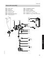
0001
0002
0003
0004
0005
0006
0007
Valve insert
Flow unit
Return unit
Overflow valve
Overflow pipe
Plate heat exchanger
Profiled gasket
0008
0009
0010
0011
0012
0013
Temperature sensor
Clip Ø 8 (5 pce)
Clip Ø 10 (5 pce)
Pipe clip Ø 18 (5 pce)
Gasket A 17 x 24 x 2 (set)
Gasket, O-ring 17.86 x 2.62 (set)
0006
0011
0002
0007
0007
0011
0011
0007
0009
0010
0008
0013
0001
0011
Service
0012
0013
0005
0012
0004
0012
0013
5618 689 UAE
0003
67
Parts lists
Control unit assembly
Control unit
Cover, wiring chamber
Fuse 2.5 A (slow) 250 V
Cable harness X20
Cable harness 100/35
0006 Cable harness stepper motor
0007 Ignition cable with angled plug
5 kΩ
0008 Cable fixing
5618 689 UAE
0001
0002
0003
0004
0005
68
Parts lists
Control unit assembly (cont.)
0002
0008
0003
0001
5618 689 UAE
Service
0004
0005
0006
0007
69
Parts lists
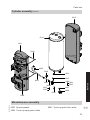
Cylinder assembly
O-ring 14.3 x 2.4 (set)
Clip Ø 15 (5 pce)
DHW connection pipe
Non-return valve (cartridge)
Shut-off elbow, cylinder
DHW connection pipe
Flat gasket
0008
0009
0010
0011
0012
0014
0015
Protective profile
Hose clip Ø 340 - 360 x 9
Cylinder
Thermal insulation EPS, front
Thermal insulation EPS, back
Strain relief
Cylinder temperature sensor NTC
5618 689 UAE
0001
0002
0003
0004
0005
0006
0007
70
Parts lists
Cylinder assembly (cont.)
0012
0010
0011
0009
0002
0002
0014
0007
0005
0001
0004
0001
0007
0001
0007
Service
0003
0007
0015
0006
0008
5618 689 UAE
Miscellaneous assembly
0001 Special grease
0002 Touch-up spray paint, white
0003 Touch-up paint stick, white
71
Parts lists
Miscellaneous assembly (cont.)
0004 Installation and service instructions
0005 Operating instructions
0001
0002
0004
0005
5618 689 UAE
0003
72
Specification
Specification
Rated voltage:
Rated frequency:
Rated current:
Safety category:
IP rating:
230 V~
50 Hz
2.0 A~
I
IP X4D to EN 60529
Temperature limiter
setting:
Backup fuse (power
supply):
100 °C (fixed)
max. 16 A
Permissible ambient temperature
■ during operation:
0 to +40 °C
■ during storage and
transport:
-20 to +65 °C
kW
kW
6.5 – 19
5.9 – 17.3
6.5 – 26
5.9 – 23.7
8.8 – 35
8.0 – 31.9
kW
5.9 – 24.0
5.9 – 29.3
8.0 – 35.0
kW
6.1 – 24.7
6.1 – 30.5
8.2 – 36.5
m3/h
kg/h
W
2.61
3.23
1.94
2.39
140
160
_-0085BT0029
3.86
2.86
185
5618 689 UAE
Note
The connection values are only for documentation purposes (e.g. in the gas contract
application) or to estimate a supplementary volumetric settings check. Due to the
factory settings, the gas pressure must not be altered from these values. Reference:
15°C, 1013 mbar.
73
Service
Rated heating output range in
heating mode
TV/TR 50/30 °C
TV/TR 80/60 °C
Rated heating output range
for DHW heating
Rated heat input range
Connection values
relative to the max. load with:
- Natural gas E
- LPG P
Power consumption (max.)
Product ID
Certificates
Declaration of conformity
Declaration of Conformity for the Vitodens 111-W
We, Viessmann Werke GmbH&Co KG, D-35107 Allendorf, confirm as sole responsible body that the product Vitodens 111-W complies with the following standards:
DIN 4753
EN 297
EN 483
EN 625
EN 677
EN 806
EN 12 897
EN 55 014-1
EN 55 014-2
EN 60 335-1
EN 60 335-2-102
EN 61 000-3-2
EN 61 000-3-3
EN 62 223
In accordance with the following Directives, this product is designated with
_-0085:
92/42/EEC
2004/108/EG
2006/95/EG
2009/142/EG
This product complies with the requirements of the Efficiency Directive
(92/42/EEC) for condensing boilers.
Allendorf, 01 March 2012
Viessmann Werke GmbH&Co KG
5618 689 UAE
Authorised signatory Manfred Sommer
74
Keyword index
Keyword index
B
Boiler water temperature sensor .......45
Burner gasket.....................................30
Burner gauze assembly.....................30
Burner installation..............................34
Burner removal..................................29
C
Cleaning the combustion chamber....32
Cleaning the heat exchanger.............32
Cold water connection.........................7
Commissioning..................................20
Condensate........................................13
Condensate drain.........................13, 33
Connection diagram...........................56
Connections...................................7, 10
Connections on the water side...........10
Cylinder temperature sensor .............46
D
Declaration of Conformity..................74
DHW connection..................................7
Draining................................................7
E
Electrical connections........................15
H
Heating curve.....................................54
Heating flow.........................................7
Heating return......................................7
I
Ignition...............................................31
Ignition electrode................................31
Ionisation electrode............................31
M
Max. heating output...........................24
O
Opening the control unit.....................15
Outlet temperature sensor.................47
Output matching
■ Flue pipe length..............................23
Outside temperature sensor .............44
P
Plate heat exchanger.........................50
Power supply.....................................17
R
Reducing the heating output..............24
Reset..................................................42
S
Safety chain ......................................48
Safety valve...................................7, 13
Siphon..........................................13, 33
Specification ......................................73
System pressure................................21
5618 689 UAE
F
Fault code..........................................39
Fault messages..................................39
Filling....................................................7
Filling function....................................20
Filling the system.........................20, 21
Flue gas temperature sensor.............49
Flue pipe............................................14
Frost limit...........................................54
Frost protection..................................54
Function sequence.............................38
Fuse...................................................51
G
Gas connection..............................7, 11
Gas type conversion
52
■ LPG................................................23
■ Natural gas.....................................52
75
Keyword index
Keyword index (cont.)
T
Temperature limiter............................48
Troubleshooting.................................43
W
Wall mounting......................................9
Weather-compensated mode.............54
Serial No.:
7487555
7499475
7499479
7499472
7499476
7499480
Viessmann Middle East FZE
E-Wing, Office 603
HQ Building
Dubai Silicon Oasis
PO Box 341330
Dubai, UAE
Tel: +971 4 3724240
Fax: +971 4 3724241
76
7499473
7499477
7499481
7499474
7499478
Viessmann Werke GmbH&Co KG
D-35107 Allendorf
Telephone: +49 6452 70-0
Fax: +49 6452 70-2780
www.viessmann.com
5618 689 UAE
Applicability
Subject to technical modifications.
V
Ventilation air pipe.............................14
Venting...............................................22