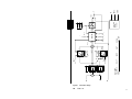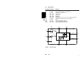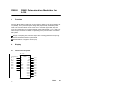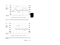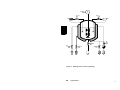
1
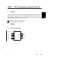
Loop CTRL → A120 → AKF
Type: CLC12
Version 1.1
Diskettes 31/2” and 51/4”
Configuration Guide
DOK-276557.20-0291
Belongs to software kit E-No. 424-271575
Overview
Notes
Table of Contents
Part I
How to Proceed?
Part II
Closed Loop Control Function Blocks
Part III
Application
Part IV
Appendix
Part V
Part VI
Part VII
Part VIII
Part IX
20
20
Notes
Table of Contents
20
v
vi
20
Notes
Application Note
Caution The relevant regulations must be observed for control
applications involving safety requirements.
For reasons of safety and to ensure compliance with documented system data, repairs to components should be performed only by the manufacturer.
Training
AEG offers suitable training that provides further information concerning the system (see addresses).
Data, Illustrations, Alterations
Data and illustration are not binding. We reserve the right to alter our products in
line with our policy of continuous product development. If you have any suggestions for improvements or amendments or have found errors in this publication,
please notify us by using the form on the last page of this publication.
Addresses
The addresses of our Regional Sales Offices, Training Centers, Service and Engineering Sales Offices in Europe are given at the end of this publication.
20
vii
Copyright
All rights reserved. No part of this document may be reproduced or transmitted
in any form or by any means, electronic or mechanical, including copying, processing or any information storage, without permission in writing by the AEG Aktiengesellschaft. You are not authorized to translate this document into any other
language.
Trademarks
All terms used in this user manual to denote AEG products are trademarks of
the AEG Aktiengesellschaft.
IBM, IBM-PC, IBM-XT and IBM-AT are registered trademarks of International
Business Machines Corporation.
Microsoft and MS-DOS are registered trademarks of Microsoft Corporation.
© 1990 AEG Aktiengesellschaft.
viii
20
Terminology
Note This symbol emphasizes very important facts.
Caution This symbol refers to frequently appearing error
sources.
Warning This symbol points to sources of danger that may
cause financial and health damages or may have other aggravating consequences.
Expert This symbol is used when a more detailed information is
given, which is intended exclusively for experts (special training required). Skipping this information does not interfere with understanding the publication and does not restrict standard application of the
product.
Path
This symbol identifies the use of paths in software menus.
Figures are given in the spelling corresponding to international practice and approved by SI (Système International d‘ Unités).
I.e. a space between the thousands and the usage of a decimal point
(e.g.: 12 345.67).
20
ix
AKF
abbr. instruction list (IL), ladder diagram (LD),
unction block diagram (FBD)
IL
instruction list
FPF
fire protection flap
DT1-part
real differential part of controller
FB
function block
HVAC
heating, ventilation and air conditioning
NW
network
P-controller
proportional-action controller
PI-controller
proportional-plus-integral controller
PID-controller
proportional-plus-integral-plus-derivative controller
PADT
programming and debugging tool
CLC-FB
closed loop control function block
PC
programmable controller
I&C
central instrumentation and control
<Cr>, <Return> use carriage-return key
<Ctrl>
use control-key
all three keys
<Alt>
use alternate-key
held down:
<Del>
use delete-key
warm restart
x
20
Objectives
Present software and documentation can only be used together with softwarepackage Dolog AKF → A120.
This manual is designed for configuration of closed-loop control programs on
Modicon A120.
It contents information about installing the software on personal computer and
the use of function blocks. The configuring of FBs (parameters, time etc.) will be
described. As an introduction into the configuration of closed-loop control programs using CLC 12C software, the software kit contains an application example
of heating, ventilation and air conditioning and the application of controlling an
reacting-tank in process engineering.
Arrangement of This Guide
General
20
This part contains the preface of the documents, describes the handling of install-disks and contains a detailed table of contents of this manual.
Part I
Checklist for proceeding with present software kit.
Part II
Requirements, installation and specification of closed-loop
control function blocks.
Part III
Installation and specification of application ‘I&C, HVAC’.
xi
Part IV
Appendix
Addresses
dresses
Publicatons Comment Form
Contain the adof the sales agencies
at home and abroad.
Please use this form a
lot, if you have any
questions or corrections regarding the
doumentation or software.
Related Documents
Software Kit
Dolog AKF → A120
Type: AKF12
E No 424-271521
Validity Note
This manual is assigned for software CLC12 version 1.1.
Translation of description DOK-275578.20.
xii
20
Handling 3 1/2” Diskettes
No cleaning of diskettes.
Store diskettes in protective
containers and boxes.
Temperature 10 to 60 C
Humidity
8 to 80%
No water on diskettes.
Insert diskettes correctly.
No erasing on diskettes.
Don’t move the metal slide.
No heavy objects on diskettes.
Diskettes tolerate no heat
(sunshine).
Label diskettes at the
right spot.
No diskettes near magnetic fields.
No forcing diskettes into
disk drive.
Always keep in mind
20
xiii
Handling 5 1/4” Diskettes
No diskettes near magnetic fields.
No cleaning of diskettes.
Insert diskettes correctly.
No erasing on diskettes.
Touch only protected parts
of diskettes.
Store diskettes in protective
containers and boxes.
No bending or folding of
diskettes.
Label diskettes at the
right spot.
Temperature 10 to 50 C
Humidity
8 to 80%
No water on diskettes.
No heavy objects on diskettes.
Diskettes tolerate no heat
(sunshine).
No painted pencils for
writing on diskettes.
No paper clips on diskettes.
No forcing diskettes into
disk drive.
Always keep in mind
xiv
20
Table of Contents
Part I
How to Proceed? . . . . . . . . . . . . . . . . . . . . . . . . 1
Chapter 1
Checklist . . . . . . . . . . . . . . . . . . . . . . . . . . . . . . . . . . . . . . . . . 3
Part II
Closed Loop Control Function Blocks . . . . 5
Chapter 1
Requirements . . . . . . . . . . . . . . . . . . . . . . . . . . . . . . . . . . . . . 7
Chapter 2
Installation of Function Blocks . . . . . . . . . . . . . . . . . . . . 9
Chapter 3
3.1
3.2
FB305
General Information about FBs . . . . . . . . . . . . . . . . . . . 11
Structure of FBs . . . . . . . . . . . . . . . . . . . . . . . . . . . . . . . . . . 12
General Information about CLC-FBs . . . . . . . . . . . . . . . . . 13
PID1.16 PID controller with 16 bit fixed point
arithmetics . . . . . . . . . . . . . . . . . . . . . . . . . . . . . . . . . . . . . . . 15
PID1.32 PID controller with 32 bit fixed point
arithmetics . . . . . . . . . . . . . . . . . . . . . . . . . . . . . . . . . . . . . . . 21
ZR1 Two-position controller for A120 . . . . . . . . . . . . . . . . 27
PDSR1 PD-step-action controller . . . . . . . . . . . . . . for A120
31
DR1 Three-position controller for A120 . . . . . . . . . . . . . . 37
PBM1 Pulse-duration Modulator for . . . . . . . . . . . . . . . A120
41
FB306
FB310
FB311
FB315
FB320
Part III
Chapter 1
1.1
1.1.1
1.1.2
20
Application . . . . . . . . . . . . . . . . . . . . . . . . . . . . . 47
Installation Application . . . . . . . . . . . . . . . . . . . . . . . . . . .
Installation of applications . . . . . . . . . . . . . . . . . . . . . . . . . .
Installation of application HVAC . . . . . . . . . . . . . . . . . . . . .
Installation of application REACT . . . . . . . . . . . . . . . . . . .
Table of Contents
49
50
50
51
xv
Chapter 2
2.1
2.2.1
Applications . . . . . . . . . . . . . . . . . . . . . . . . . . . . . . . . . . . . . 53
Open Loop and Temperature Control of a Ventilation System in HVAC Techniques . . . . . . . . . . . . . . . . . . . . . . . . . . 56
Open Loop Control . . . . . . . . . . . . . . . . . . . . . . . . . . . . . . . . 59
Mixed air temperature control . . . . . . . . . . . . . . . . . . . . . . . 62
Room Temperature Control . . . . . . . . . . . . . . . . . . . . . . . . . 63
Closed Loop Control of a Reacting Tank in Process Engineering . . . . . . . . . . . . . . . . . . . . . . . . . . . . . . . . . . . . . . . . . . 66
Sequence Control and Closed Loop Control . . . . . . . . . . 66
Part IV
Appendix . . . . . . . . . . . . . . . . . . . . . . . . . . . . . . 69
2.1.1
2.1.2
2.1.3
2.2
Addresses . . . . . . . . . . . . . . . . . . . . . . . . . . . . . . . . . . . . . . . 71
Publications Comment Form . . . . . . . . . . . . . . . . . . . . . 81
xvi
Table of Contents
20
Part I
How to Proceed?
20
1
2
20
Chapter 1
Checklist
The following list describes how to use this closed-loop control
manual and how to handle the loop control software in the best
way.
20
Checklist
3
Before using loop control function blocks take a look at the following checklist
and note the software details in the corresponding chapters.
Get familiar with the conditions for using loop control software (part II, chapter
1).
Have you fullfilled the conditions of the first point?
Install the loop control function blocks (part II, chapter 2).
To check software operation, install one of the applications (part III, chapter1).
Start AKF program using the ‘AKF12’-command on your PADT (see also software kit ‘AKF12’).
With SeTup menu type the name of ‘PLant’ and ‘PC Station’ that you want to
choose for applications (see also software kit ‘AKF12’).
Print closed-loop control program using print menu ‘program list’ (see also
software kit ‘AKF12’).
Get familiar to functionality of application using the program list and the manual‘s descriptions (see also software kit ‘AKF12’).
Edit your open loop program using ‘AKF12’ (see also software kit ‘AKF12’).
Copy the neecessary loop control Function Blocks to your actual plant using
the ‘Special’ and ‘Copy Files’ commands (see also software kit ‘AKF12’).
Create your closed loop program under using the function blocks (see also
part II).
The specific closed-loop control parts are now complete. Finally you can prepare
the AKF program for loading it to the connect PC or return to other work on the
given plant (AKF12, part ‘programming’, chap. ‘Programming Sequence’).
4
Checklist
20
Part II
Closed Loop Control
Function Blocks
20
5
6
20
Chapter 1
Requirements
This chapter enables you to perform closed loop control using
AKF software package Dolog AKF → A120 and the loop control
software CLC 12.
20
Requirements
7
To guarantee proper operation of software ensure the following conditions:
IBM compatible programming and debugging tool (personal computer) with
fixed disk drive and external-disk drive (3 1/2” or 5 1/4”) and with installed
software Dolog AKF → A120
software conditions:
Kind of software
A120:
ALU 200 basic software
ALU 201 basic software
ALU 202 basic software
PADT:
Dolog AKF → A120
programming software
Loop CTRL → A120 → AKF
Closed loop control FBs
type
number
BSW 124
BSW 123
BSW 123
275121.00
275120.00
275120.00
AKF12
E-Nr. 424-247197 version 2.0 or higher
CLC12
E-Nr. 424-271575 version 1.0
Knowledge about project planning of the A120 using the software kit
Dolog AKF → A120
8
Requirements
20
Chapter 2
Installation of Function
Blocks
This chapter describes you how to copy closed loop control function blocks.
20
Installation of Function Blocks
9
The loop control function blocks (CLC-FBs) are equipped with AEG defined numbers. Nevertheless these numbers can be freely changed by the customer when
copying function blocks from diskette to PC Station. To keep always best survey
and to make survive activities less difficult, we recommend to use the same
numbers or to commit function block numbers in your company.
Use the following procedure to copy FBs:
Step 1
Start AKF12 program
Step 2
Insert CLC12-diskette in your disk drive (e.g. A:\)
Step 3
You are in the Plant, entered during installation of AKF12
(e.g. ”C:\AKF12”)
Step 4
Select ”SeTup”, ”PC Station”, ”PC Station Name” in
AKF12 menu (e.g. ”CLC”)
Step 5
Select menu ”Special”, ”Copy Files”
Step 6
To specify source files type: A:\CLC12\*.* (note A:\ is the
name of disk drive in which youve inserted the CLC12 diskette, eventually this drive can be B:\ )
Step 7
When entering the return key in the ”Target” line (empty
line), the files on the inserted diskette will be copied into
the PC station determined with SeTup (CLC12)
Menu entries for step 6 and
step 7:
(parameter: /V)
Start Copying Files
SOurce: A:\CLC12\*.*
Target:
Parameter: /V
From this PC station the required FBs can be copied to the actual PC station
containing the user program (the recommendation mentioned above is automatically kept when proceeding in this way).
For this Step 4 to Step 7 have to be repeated.
To Step 4: Type the name of PC station you want to work with.
To Step 6: ”Source” is the directory of PC station ”CLC”. Instead of *.* insert the
number of required FB.
To Step 7: The selected PC station remains the target directory.
10
Installation of Function Blocks
20
Chapter 3
General Information about
FBs
20
General Information about FBs
11
3.1
Structure of FBs
Every function block consists of one operation and the necessary operands for
executing the operation.
The operation determinates which function will be executed by the function
block. The operand determinates which variable will be used when executing
the operation.
Function Block
Operand
actual operand
assignable
operand
Operation
e.g. ZR1
e.g. ER,X
operand
identifier
e.g. MW, M
Parameter
e.g. 2.3, 4.5
FB 310
Condition
M...
M...
MW..
MW..
MW..
MW..
ZR1
ER
ER
WE
XE
HYS
TA
YA
TM
VIM1
VIM2
VIW1
VIW2
MW..
T...
M...
M...
MW..
MW..
Note Only one FB is allowed in each network
Conditional- / unconditional FB call
The operation of every function block can be enabled with a ‘Conditional call’
(edit menu). Doing this causes AKF program to perform an additional FB marker
input. Setting the conditional input enables FB operation, resetting the input turns
the FB operation off. The output operands then will not be changed until the FB
is reactivated. This allows for instances where output operands are shared with
12
General Information about FBs
20
further FBs in cases of process dependant operating modes (e.g. split-range
control) - or simply to stop FB operation. The conditional input is next to the
name of function block (here ZR1).
Conditional input e.g. E2.1 → conditional call
→ unconditional call
no conditional input
The operand identifier determinates if it is e.g. an output variable (Q), Input variable (I), a marker byte (MB) etc. This information is demanded by Dolog AKF
from the system. It is not possible to write a marker bit to places which are assigned for marker words. Wrong inputs will not be accepted (syntax check).
Valid characters of variables in Function Block Diagrams:
Condition conditional or unconditional call (enable) of function block
M...
for input/output value or marker with bit format
MB..
for input/output value or marker with byte format
MW..
for input/output value or marker with word format
MD..
for input/output value or marker with double word format
The points signify the required parameters
3.2
General Information about CLC-FBs
The Closed Loop Function Blocks of MODICON A120 can be copied into an existing PC station and used like regular FBs.
Inserting a Function Block into a Network causes the AKF program to prepare
the finally program linkage with assignment of fundamental part of Function
Block code and additional the code for calling the FB in OB (see also FB descriptions). With every further insertion of the same Function Block only the call
of the new FB is added to the code to be linked. The required program memory
can be kept to a minimum in this way.
The Loop Control Function Blocks run without additional timing system using
only timer controlled sampling. Therefore every CLC-FB gets one or more timer
functions assigned at TMx variable. The sampling time, unless otherwise specified (see FB descriptions), should be determinated adapt to the conditions of
20
General Information about FBs
13
process loop. Usual values are 1/5 - 1/10 of loop control relevant system time
constants.
The required memory allocation for internal variables, controller input- and output
variables and controller parameters are completely assigned at the Controller
Function Block. There is no exceptional handling of data in the Data Block (DB)
or consideration of restricted data areas.
The number of timer addresses used can be minimized by assigning the same
timers to several function blocks in cases when the sampling time is determined
as zero. (e.g. ZR1-, DR1 continuous operation or PID controller in P controller
mode). Also the double words that have to be assigned to some controllers can
be used commonly. They are only used for buffer storage.
In displaying A120 signals using ”Online List” it should be considered that variables identified as controllable (CE) will be overwritten for one program cycle
with given list value after activating the transmit using the transmit command in
the AKF menu. The controller outputs have storing characteristics and therefore
should only be listed as viewable (no identifier). Identifying controller output variables as force variables should be avoided if regular and continual controller operation is to be guaranteed. (The fixing of output variables causes uncontrollable
influence in FB operation)
14
General Information about FBs
20
FB305
1
PID1.16 PID controller with
16 bit fixed point arithmetic
Function
The closed loop control function block PID 1.16 is a freely parametrizable PID
controller with 16 bit fixed point arithmetics. PID 1.16 has the following characteristics
negative KP values possible (change of control direction)
D-, and I-part can separately and bumpless turned on/turned off
D-part with bumpless change over to system deviation or actual value
D-part part combined with 1st order lag element for controlled step response
(DT1)
Operation with anti windup reset (AWR)
Manual input with setpoint correction of integral part for bumpless return to
automatic mode
Operating mode HALT for keeping the last value of controller output with setpoint correction of integral part
Dynamic HALT with positive edge trigger at DHLT-input during next FB cycle
Limiting of controller output to minimum/maximum value
Complete protection against arithmetic overflows; thus higher reliability
FB operating time less than 10 ms
20
PID1.16
15
2
Display
2.1
Funktion Block Symbol
FB 305
Condition
MW..
MW..
MW..
MW..
MW..
M...
M...
M...
MW..
MW..
MW..
M...
MW..
16
PID1.16
W
Y
X
TM
YH
VIM1
YAO
VIM2
YAU
VIW1
HAND
VIW2
HALT
VIW3
DHLT
VIW4
KP
VIW5
TN
VIW6
TV
VIW7
VIW8
ED
TA
PID1.16
MW..
T...
M...
M...
MW..
MW..
MW..
MW..
MW..
MW..
MW..
MW..
20
2.2
FB structure
Assignable parameter
Meaning
PID1.16
W
X
YH
YAO
YAU
HAND
HALT
DHLT
KP
TN
TV
ED
TA
Y
TM
VIM1
VIM2
VIW1
VIW2
VIW3
VIW4
VIW5
VIW6
VIW7
VIW8
Operation (Call)
setpoint value
actual value
manual input
maximum output value
minimum output value
operating mode HAND (priority over HALT)
operating mode HALT
dynamic HALT for next FB cycle
controller gain
integral-action time (in 0.1 s); TN < 0: I-part is turned off
derivative-action time (in 0.1 s); TV < 0: D-part is turned off
change over D-part (0 for KP * Xd, 1 for KP * -X)
sampling time (in 0.1 s)
manipulated variable (controller output)
timer
internal organization data (bit)
internal organization data (bit)
internal organization data (word)
internal organization data (word)
internal organization data (word)
internal organization data (word)
internal organization data (word)
internal organization data (word)
internal organization data (word)
internal organization data (word)
20
MW - addr.
MW - addr.
MW - addr.
MW - addr.
MW - addr.
M - addr.
M - addr.
M - addr.
MW - addr.
MW - addr.
MW - addr.
M - addr.
MW - addr.
MW - addr.
T - addr.
M - addr.
M - addr.
MW - addr.
MW - addr.
MW - addr.
MW - addr.
MW - addr.
MW - addr.
MW - addr.
MW - addr.
PID1.16
17
Figure 1
18
Controller design
PID1.16
20
YH
X
W
-KP
1
TV = 0
(Xe)
ED
TN = 0
T1 = (1/4) TV
Xd(i--1)
4 *Xe
TV
(Xd * KP)
TN
Xi(i--1)
P
DT1
Xd(i--1)
I
HIGH
TN = 0
AWR
1
1
LOW
1
1
DHLT HAND HALT
Y**
Xi(i--1)
Priority AWR:
TN = 0/TV = 0 . . . . . DHLT . . . . .HAND . . . . .HALT . . . . .Limiting
_
Xd
KP
1
Y*
Functtion
Block
Control
YAU
YAO
HAND
SM19
SM02
TA
Y
3
Configuration
The function block can be copied from the source file (PADT or Diskette) to the
target file of the selected PC station (ref. chapter LEERER MERKER).
3.1 Parametrization
The parametrization of PID 1.16 controller has no restrictions - Arithmetic overflows will be kept MAXINT limits the way that direction (sign) of substituted variable is the same as the direction of the unrepresentable, overshoot one (no undefined ‘saw-teeth’ effects). Controller operation without limited output value can
be reached with regards to the overall arrangement of control loop.
Note :
Step changes in setpoint value will be amplified with a gain of 5 * KP at the instant of step change and are given out additional to the actual controller output
value (once amplified by controller gain and four times by DT1-part, because of
internal determination TV/T1 = 4).
The following course of the controller output value is essentially determined by
the additional conditions of the control loop, mostly by system time constants.
The limiting of controller output in this connection, is in the main dependant on
the course of the integral part, whose settling to an fixed value can only be done
over the system loop.
Step changes in setpoint value can be (preferably in PI mode) transformed into a
slower settling of the control loop, with bumpless change in controller output value, when simultaneous causing a positive edge trigger at DHLT input. In that
case DHLT forces the controller to take over the normally occuring step change
in the controller output into the integral part (one cycle). The former controller
output value temporary remains as the output value. The following course of
controller output value is essentially determinated by the changing of the integral
part.
20
PID1.16
19
Table 1
Determination of sampling time
Controller
min
typ
max
P
PI
PD
PID
0
-
< 0.2*TN
< 0.05*TV
< 0.05*TV
-
3.2
FB operating times
Note The given operating times are valid when using ALU 202.
Operating times during sampling cycle:
mode
Controller
normal
AWR**
HAND
P
PI
PD
PID
3.08
5.06
3.79
5.41
3.20
4.25
3.62
4.46
2.98
4.02
2.99
4.03
ms
ms
ms
ms
ms
ms
ms
ms
HALT
ms
ms
ms
ms
3.01
4.03
3.02
4.94
ms
ms
ms
ms
Operating times in other cycles:
always
2.32 ms
3.3 Program memory
first FB-call in OB:
5 010
every further call:
+ 159
Byte*
Byte
** if I part works
* The given value represents worst case value and is valid when the Function
Block is the only one called in the OB. If however commands used in your
closed loop control functions already exist in your program, only the additional
program parts will cause an increase in the total linked program length (hence
saving in program memory).
20
PID1.16
20
FB306
1
PID1.32 PID controller with
32 bit fixed point arithmetics
Function
The Closed Loop Control Function Block PID 1.16 is a freely parameterizable
PID controller with 16 bit fixed point arithmetics for input and output. The calculation of I- and DT1-part and the summing of the internal values for building the
controller output signal are done with 32 bit accuracy.
negative KP values possible (change of control direction)
D-, and I-part can separately and bumplessly turned on/off
D-part with bumpless change over to system deviation or actual value
D-part part combined with 1st order lag element for controlled step response
(DT1)
Operation with anti windup reset (AWR)
Manual input with setpoint correction of integral part for bumpless return to
automatic mode
Operating mode HALT for keeping the last value of controller output with setpoint correction of integral part
Dynamic HALT with positive edge trigger at DHLT-input during next FB cycle
Limiting of controller output to minimum/maximum value
Complete protection against arithmetic overflows; thus higher reliability
FB operating time less than 10 ms
20
PID1.32
21
2
Display
FB 306
condition
MW..
MW..
MW..
MW..
MW..
M...
M...
M...
MW..
MW..
MW..
M...
MW..
22
PID1.32
W
Y
X
TM
YH
VIM1
YAO
VIM2
YAU
VIW1
HAND
VIW2
HALT
VIW3
DHLT
VIW4
KP
VIW5
TN
VIW6
VIW7
TV
VIW8
ED
TA
VIW9
VID1
VID2
PID1.32
MW..
T...
M...
M...
MW..
MW..
MW..
MW..
MW..
MW..
MW..
MW..
MW..
MD..
MD..
20
2.1
FB structure
Assignable parameter
Meaning
PID1.32
W
X
YH
YAO
YAU
HAND
HALT
DHLT
KP
TN
TV
ED
TA
Y
TM
VIM1
VIM2
VIW1
VIW2
VIW3
VIW4
VIW5
VIW6
VIW7
VIW8
VIW9
VID1
VID2
Operation (Call)
setpoint value
actual value
manual input
maximum output value
minimum output value
operating mode HAND (priority over HALT)
operating mode HALT
dynamic HALT for next FB cycle
controller gain
integral-action time (in 0.1 s); TN < 0: I-part is turned off
derivative-action time (in 0.1 s); TV < 0: D-part is turned off
change over D-part (0 for KP * Xd, 1 for KP * -X)
sampling time (in 0.1 s)
manipulated variable (controller output)
timer
internal organization data (bit)
internal organization data (bit)
internal organization data (word)
internal organization data (word)
internal organization data (word)
internal organization data (word)
internal organization data (word)
internal organization data (word)
internal organization data (word)
internal organization data (word)
internal organization data (word)
internal organization data (double word)
internal organization data (double word)
20
MW - addr.
MW - addr.
MW - addr.
MW - addr.
MW - addr.
M - addr.
M - addr.
M - addr.
MW - addr.
MW - addr.
MW - addr.
M - addr.
MW - addr.
MW - addr.
T - addr.
M - addr.
M - addr.
MW - addr.
MW - addr.
MW - addr.
MW - addr.
MW - addr.
MW - addr.
MW - addr.
MW - addr.
MW - addr.
MD - addr.
MD - addr.
PID1.32
23
Figure 2
24
Controller design
PID1.32
20
YH
X
W
-KP
1
TV = 0
(Xe)
ED
TN = 0
T1 = (1/4) TV
Xd(i--1)
4 *Xe
TV
(Xd * KP)
TN
Xi(i--1)
P
DT1
Xd(i--1)
I
HIGH
TN = 0
AWR
1
1
LOW
1
1
DHLT HAND HALT
Y**
Xi(i--1)
Priority AWR:
TN = 0/TV = 0 . . . . . DHLT . . . . .HAND . . . . .HALT . . . . .Limiting
_
Xd
KP
1
Y*
Function Block
Control
YAU
YAO
HAND
SM19
SM02
TA
Y
3
Configuration
The function block can be copied from source file (PADT or Diskette) to the target file of the selected PC station (ref. chapter LEERER MERKER).
3.1 Parameterization
The parametrization of PID 1.16 controller has no restrictions - Arithmetic overflows will be kept within MAXINT limits the way that direction (sign) of substituted
variable is the same as the direction of the unrepresentable, overshooten one
(no undefined ‘saw-teeth’ effects). Controller operation without limited output value can be reached with regards to the overall arrangement of control loop.
Note :
Step changes in setpoint value will be amplified with a gain of 5 * KP at the instant of step change and are given out additional to the actual controller output
value (once amplified by controller gain and four times by DT1-part, because of
internal determination TV/T1 = 4).
The following course of the controller output value is essentially determined by
the additional conditions of the control loop, mostly by system time constants.
The limiting of controller output in this connection, is in the main dependant on
the course of the integral part whose settling to an fixed value can only be done
over the system loop.
Step changes in setpoint value can be (preferably in PI mode) transformed into a
slower settling of the control loop, with bumpless change in controller output value, when simultaneousley causing a positive edge trigger at DHLT input. In that
case DHLT forces the controller to take over the normally occuring step change
in the controller output into the integral part (one cycle). The former controller
output value temporary remains as the output value. The following course of
controller output value is essentially determinated by the changing of the integral
part.
20
PID1.32
25
Table 2
Determination of sampling time
Controller
min
typ
max
P
PI
PD
PID
0
-
< 0.2*TN
< 0.05*TV
< 0.05*TV
-
3.2
FB operating times
Note The given operating times are valid when using ALU 202.
Operating times during sampling cycle:
mode
Controller
normal
AWR
P
PI
PD
PID
3.43
8.74
3.79
9.1
3.64
6.42
4.0
6.78
ms
ms
ms
ms
HAND
ms
ms
ms
ms
3.27
6.29
3.27
6.29
HALT
ms
ms
ms
ms
3.27
8.7
3.27
8.73
ms
ms
ms
ms
Operating times in other cycles:
always
2.56
ms
3.3 Program memory
first FB-call in OB:
6 150
every further call:
+ 177
Byte*
Byte
* The given value represents worst case value and is valid when the function
block is the only one called in OB. If however commands used in your closed
loop control functions already exist in your program, only the additional program
parts will cause an increase in the total linked program length (hence saving in
program memory).
26
PID1.32
20
FB310
1
ZR1 Two-position controller for A120
Function
The Function Block ZR1 transforms an internally formed system deviation into a
binary state for the output marker YA. If the absolute value of the system deviation (WE-XE) overranges by a half of the hysteresys value (HYS) the output will
be set dependant (sign) on the deviation value.
Assigning hysteresis and sampling time
Continuous operation setting TA = 0
2
Display
2.1
Function block symbol
FB 310
Condition
M...
M...
MW..
MW..
MW..
MW..
20
ZR1
ER
EF
WE
XE
HYS
TA
YA
TM
VIM1
VIW1
VIW2
M...
T...
M...
MW..
MW..
ZR1
27
2.2
FB structure
Assignable parameter
Meaning
ZR1
ER
EF
WE
XE
HYS
TA
YA
TM
VIM1
VIW1
VIW2
Operation (Call)
function block reset; ER = 1: reset of YA
enable: EF = 0: freezes YA
setpoint value
actual value
hysteresis
sampling time (in 0.1 s); TA = 0 for continuous operation
manipulated variable (controller output signal)
timer
internal organization data (bit)
internal organization data (word)
internal organization data (word)
B - addr.
B - addr.
MW - addr.
MW - addr.
MW - addr.
MW - addr.
M - addr.
T - addr.
M - addr.
MW - addr.
MW - addr.
TM
HYS
TA
t
Sampling Time
HYS
YA
Xd
WE
1
YA
-Xd
XE
EF
Figure 3
28
ER
controller design
ZR1
20
3
Configuration
The Function Block can be copied from source file (PADT or diskette) to the target file of selected PC station (ref. chapter LEERER MERKER).
3.1 Parameterization
The parameterization of ZR1 ensues with the assignment of the hysteresis and
sampling times.
The hysteresis defines the operating points of the controller. Outside the hysteresis the system deviation causes ZR1 to switch the output depending on the sign
of the deviation. Inside the hysteresis area ZR1 operates like a dead zone with
stored output.
To select the sampling time is an option that can be done to synchronize ZR1
with other controllers. If synchronizing is not necessary the Function Blocks can
be enabled to work in every program cycle by setting sampling time TA=0.
3.2 Reset of Function Block
ER = 1 reset of output marker YA.
EF = 0 no change in output marker condition even when the system deviation or
controller parameters are changing.
3.3
FB operating times
Note The given operating times are valid when using ALU 202.
Operating conditions :
ER = 1
0.52 ms
EF = 0
0.47 ms
ER = 0, EF = 1 1.5 ms
20
ZR1
29
3.4 Program memory
first FB-call in OB:
1 596
every further call:
+ 75
Byte*
Byte
* The given value represents worst case value and is valid when the function
block is the only one called in OB. If however commands used in your closed
loop control functions already exist in your program, only the additional program
parts will cause an increase in the total linked program length (hence saving in
program memory).
30
ZR1
20
FB311
1
PDSR1 PD-step-action controller
for A120
Function
The Function Block PDSR1 consists of a three-position controller hysteresis and
a 1st order lag feedback loop. The internal coupling of 1st order lag element
from controller output to the input summing point approaches controller characteristics of those in continuously sampling PD controllers (supposing relatively
high system- and actuator time constants for efficient filtering of switched output
signal). When connected with an integral actuator (e.g. control valve) the actuator/controller combination has PI characteristics. The parameterization is simplified by the direct assignment of the actuator-action time (nominal value of the
valve) and the required parameters KP and TN. The determination of feedbackand hysteresis value is done by the controller itself.
Parameterization of controller gain, integral action time, actuator action time
and scaling value
Internal determination of feedback- and hysteresis values
Accommodation of the controller operation to the process conditions by the
use of the scaling value KSN
20
PDSR1
31
2
Display
2.1
Function block symbol
FB 311
Condition
M...
M...
MW..
MW..
MW..
MW..
MW..
MW..
2.2
PDSR1
ER
EF
WE
XE
KP
TN
TS
KSN
YP
YN
TM1
VIM1
VIW1
VIW2
VIW3
VIW4
VID1
VID2
MW..
MW..
T...
M...
MW..
MW..
MW..
MW..
MD..
MD..
FB structure
Assignable parameter
Meaning
PDSR1
ER
EF
WE
XE
KP
TN
TS
KSN
YP
YN
TM1
VIM1
VIW1
VIW2
VIW3
VIW4
VID1
VID2
Operation (Call)
function block reset; ER = 1: reset of YA
enable: EF = 0: freezes YP, YN
setpoint value
actual value
controller gain
integral-action time (in s)
nominal actuating time of integral actuator (in s)
scaled process gain
controller output for positive directed actuating
controller output for negative directed actuating
timer
internal organization data (bit)
internal organization data (word)
internal organization data (word)
internal organization data (word)
internal organization data (word)
internal organization data (double word)
internal organization data (double word)
32
B - addr
B - addr
MW - addr
MW - addr
MW - addr
MW - addr
MW - addr
MW - addr
M - addr
M - addr
T - addr
M - addr
MW - addr
MW - addr
MW - addr
MW - addr
MD - addr
MD - addr
PDSR1
20
2.3
FB structure
TM1
TN
ER
KSN
Function Block
Control
K=1
EF
KR
TA = 100 ms
YP
YP
-WE
Xd
Y
--
YN
YN
XE
KR
HYS
UZ
UZ
KSN
KP
Figure 4
20
HYS
Conversion
TN
TS
Controller design
PDSR1
33
3
Configuration
The Function Block can be copied from the source file (PADT or diskette) to the
target file of the selected PC station (ref. chapter LEERER MERKER).
3.1 Parameterization
The parameterization of PDSR1 is carried out by the assignment of the controller
gain, integral-action time, the nominal actuating time of integral actuator and the
scaled process gain.
The gain of the 1st order lag feedback element is a function of scaled process
gain KSN. Therefore KSN has to be determinated in relation to input scaling of
controller setpoint- and actual value. For instance - a theoretical temperature
range of +/-400 oC that refers to +/- 4000 integer value (e.g. scaling an input
voltage signal of ADU204 ) results an input scaling of 10/ oC. If the maximum
difference in process temperature (actual value between the states - shut down
valve and widely opened valve- ) results to KS = 200oC the scaled process gain
is given to KSN = 2000.
The scaling accommodates the switching of the controller outputs to the appropriate switching of an integer value for feedback circuitry. In this way the transposition of the given parameters will be guaranteed and the handling of control
loop can be done close to that of continuously operating loops.
To keep the developing controller attributes close to the determinated parameters the following values have to be selected:
Parameter
min
type
max
KP
TN
TS
1
120
30
> 4*TS
< TN/4
-
(s)
(s)
The hysteresis determines the controller sensitivity and is internally calculated
the way:
HYS = KSN / (KP*TS)
34
PDSR1
20
When the scaling setpoint- and actual value to a function of twice the process
gain (exampled above) the resolution error reaches at the most 1.66 %. If the
user determination of integer range (not the scaling, hence KSN = constant) this
is defined otherwise, the resolution changes while the absolute error remains the
same.
3.2 Reset of Function Block
ER = 1 reset of output markers YP and YN.
EF = 0 no change in condition of output markers even when the system deviation or controller parameters are changing.
3.3
FB operating times
Note The given operating times are valid when using ALU 202.
Operating conditions:
ER = 1
0.76
EF = 0
0.67
ER = 0, EF = 1 7.0
ms
ms
ms
3.4 Program memory
first FB-call in OB:
3 903
every further call:
+ 117
Byte*
Byte
* The given value represents worst case value and is valid when the function
block is the only one called in OB. If however commands used in your closed
loop control functions already exist in your program, only the additional program
parts will cause an increase in the total linked program length (hence saving in
program memory).
20
PDSR1
35
FB315
1
DR1 Three-position controller for A120
Function
The Function Block DR1 transforms an internally formed system deviation into
binary states for output markers YP and YN. If the absolute value of the system
deviation (WE-XE) overranges by half of the hysteresys value (HYS) which is
shifted by dead band (UZ), the output will be set dependant (sign) on the deviation value (if positive - YP, if negative - YN). If system deviation falls below the
value marked by the inner edge of appropriate hysteresis loop the marker will be
reset. Overlapping of hysteresis loops can be done up to HYS = 2 * UZ
Assigning hysteresis, dead band and sampling time
Operation up to HYS = 2 * UZ possible
Continuous operation setting TA = 0
2
Display
2.1
Function block symbol
FB 315
Condition
M...
M...
MW..
MW..
MW..
MW..
MW..
20
DR1
ER
EF
WE
XE
HYS
UZ
TA
YP
YN
TM
VIM1
VIW1
VIW2
M...
M...
T...
M...
MW..
MW..
DR1
37
2.2
FB structure
Assignable parameter
Meaning
DR1
ER
EF
WE
XE
HYS
UZ
TA
YA
TM
VIM1
VIW1
VIW2
Operation (Call)
function block reset; ER = 1: reset of YA
enable: EF = 0: freezes YA
setpoint value
actual value
hysteresis
dead band
sampling time (in 0.1 s); TA = 0 for continuous operation
manipulated variable (controller output signal)
timer
internal organization data (bit)
internal organization data (word)
internal organization data (word)
B - addr.
B - addr.
MW - addr.
MW - addr.
MW - addr.
MW - addr.
MW - addr.
M - addr.
T - addr.
M - addr.
MW - addr.
MW - addr.
UZ
TM
TA
HYS
t
Cycle time
pos.
YP
YA
Xd
WE
HYS
YP
Xd
UZ
--
neg.
YN
YN
XE
EF
Figure 5
38
ER
controller design
DR1
20
3
Configuration
The Function Block can be copied from the source file (PADT or diskette) to the
target file of the selected PC station (ref. chapter LEERER MERKER).
3.1 Parameterization
The parameterization of Function Block ensues with assignement of hysteresis,
dead band and sampling time. The hysteresis defines the operating points of the
controller. Outside the hysteresis the system deviation causes DR1 to switch the
appropriate output depending on the sign of the deviation. Inside the hysteresis
area DR1 keeps the current output states as long as deviation does not overrange (underrange) the corresponding operating point (if high state - falling edge
of hysteresis, if low state - rising edge of hysteresis). The separation of the deviation area for the use of two controller outputs allows the design of loop controls
with separate control actions (split-range control, e.g. heating and cooling). The
select sampling time TA is optional and can be used to synchronize DR1 with
other controllers. If synchronization is not necessary the Function Blocks can be
enabled to work in every program cycle by setting sampling time TA=0.
3.2 Reset of Function Block
ER = 1 reset of output markers YP and YN.
EF = 0 no change in condition of output markers even when the system deviation or controller parameters are changing.
3.3
FB operating times
Note The given operating times are valid when using ALU 202.
Operating conditions :
ER = 1
0.6 ms
EF = 0
0.53 ms
ER = 0, EF = 1 1.2 ms
20
DR1
39
3.4 Program memory
first FB-call in OB:
1 623
every further call:
+ 87
Byte*
Byte
* The given value represents worst case value and is valid when the function
block is the only one called in OB. If however commands used in your closed
loop control functions already exist in your program, only the additional program
parts will cause an increase in the total linked program length (hence saving in
program memory).
40
DR1
20
FB320
1
PBM1 Pulse-duration Modulator for
A120
Function
Function Block PBM1 transforms an input signal, related to the given limiting value (OBGR), into a periodical pulse string with proportionally modulated pulsewidth. The Function Block can be used as a P-controller (input WE, XE) and
even as a transformer for continual signals (input WE with XE = 0) e.g. PID controller output connected to PBM1 for operating a two-point actuator of controllable system.
Assign of sampling time, absolute input value causing permanent output signal and minimum/maximum pulse-width
Transformation of negative values (YN)
2
Display
2.1
Function block symbol
FB 320
Condition
M...
M...
MW..
MW..
MW..
MW..
MW..
MW..
20
PBM1
ER
EF
WE
XE
OBGR
TTK
TMAX
TMIN
YP
YN
TM1
TM2
VIM1
VIM2
VIM3
VIM4
VIW1
VIW2
VID1
VID2
M...
M...
T...
T...
M...
M...
M...
M...
MW..
MW..
MD..
MD..
PBM1
41
2.2
FB structure
Assignable parameter
Meaning
PBM1
ER
EF
WE
XE
OBGR
TTK
TMAX
TMIN
YP
YN
TM1
TM2
VIM1
VIM2
VIM3
VIM4
VIW1
VIW2
VID1
VID2
Operation (Call)
function block reset; ER = 1: reset of YA
enable: EF = 0: freezes YA
setpoint value
actual value
limiting value (absolute)
sampling time (in s)
maximum pulse time (in s)
minimum pulse time (in s)
output signal for positive directed actuation
output signal for negative directed actuation
1st timer
2nd timer
internal organization data (bit)
internal organization data (bit)
internal organization data (bit)
internal organization data (bit)
internal organization data (word)
internal organization data (word)
internal organization data (double word)
internal organization data (double word)
3
B - addr.
B - addr.
MW - addr.
MW - addr.
MW - addr.
MW - addr.
MW - addr.
MW - addr.
M - addr.
M - addr.
T - addr.
T - addr.
M - addr.
M - addr.
M - addr.
M - addr.
MW - addr.
MW - addr.
MD - addr.
MD - addr.
Configuration
The Function Block can be copied from the source file (PADT or diskette) to the
target file of selected PC station (ref. chapter LEERER MERKER).
42
PBM1
20
3.1 Parameterization
The parameterization of PBM1 ensues with assignment of the limiting value, the
sampling time and minimum/maximum pulse-width.
TTK determines the sampling time in which the actuating pulses are periodically
given out to the controller outputs YP or YN. The actual pulse-width and thereby
the averaged proportionality ym of the actuating pulses are dependant on the relation of the input value (system deviation or setpoint) to the limiting value
(OBGR).
Tp =
ym =
WE -- XE
OBGR
WE -- XE
OBGR
*
TTK
* 100%
If the pulse-width underranges the given value TMIN the controller outputs are
turned to low.
If pulse-width overranges the given value TMAX, the pulse-width will be limited
to TMAX. Both measures ensure correct opeation between the modulator and
the characteristics of a given actuator.
When assigning TMIN = 0 and TMAX = TTK the pulse-width is not restricted this
way.
Note To keep the developing controller attributes as close to the determinated parameters the following values should be selected:
Parameter
min
type
max
OBGR
TTK
TMAX
TMIN
10
0
-< TTK
< TMAX
-3200 (s)
-
20
PBM1
43
3.2 Reset of Function Block
ER = 1 reset of output markers YP and YN.
EF = 0 no change in condition of output markers even when the system deviation or controller parameters are changing.
3.3
FB operating times
Note The given operating times are valid when using ALU 202.
Operating conditions :
ER = 1
0.83 ms
EF = 0
0.73 ms
ER = 0, EF = 1 > 1.5 ms (3.45 ms maximum)
3.4 Program memory
first FB-call in OB:
3 309
every further call:
+ 129
Byte*
Byte
* The given value represents worst case value and is valid when the function
block is the only one called in OB. If however commands used in your closed
loop control functions already exist in your program, only the additional program
parts will cause an increase in the total linked program length (hence saving in
program memory).
44
PBM1
20
TTK
Ti
smallest
impulse time
free controller range
possible clockgrid
t
transient
impulse length
Output
Tp
t
EF = 1
Output signal = 0
when Tp < TMIN
t
EF = 1
Output signal
when
Tp > TMAX
TMAX
t
Figure 6
20
Clock grid and pulse-shaping
PBM1
45
Tp
at VP
TTK
T MIN
T MAX
-- Xd
OBGR
OBGR
Xd
T MIN
T MAX
TTK
--Tp
Figure 7
46
at YN
Transfer characteristics
PBM1
20
Part III
Application
20
47
48
20
Chapter 1
Installation Application
This chapter tells you how to copy the applications of the AKF12
Closed Loop Control.
20
Installation Application
49
1.1
Installation of applications
The enclosed diskette contains two applications as example of close loop control
using AKF12.
1.1.1
Installation of application HVAC
Application of heating ventilation and air conditioning : ”HVAC”
Use the following procedure with the application:
Step1
Start AKF12 program
Step2
Insert CLC12-diskette in your disk drive (e.g. A:\)
Step3
You are in the Plant, entered during installation of AKF12
(e.g. ”C:\AKF12”)
Step4
Enter in the the AKF12 menu the station ”HVAC” under
”SeTup”, ”PC Station”, ”PC Station Name”
Step5
Select menu ”Special”, ”Copy Files”
Step6
To specify source files type: A:\CLC12\*.* (note A:\ is the
name of disk drive in which youve inserted the CLC12 diskette, eventually this drive can be B:\ )
Step7
When entering the return key in the ”Target” line (empty
line), the files on the inserted diskette will be copied into
the PC station determined with SeTup (CLC12)
Menu entries for step 6 and
step 7:
(parameter: /V)
Start Copying Files
SOurce: A:\CLC12\*.*
Target:
Parameter: /V
Now you can take a look at the PC station ”HVAC”.
50
Installation Application
20
1.1.2
Installation of application REACT
Application of a reacting tank in process engineering: ”REACT”
Use the following procedure with the application:
Step1
Start AKF12 program
Step2
Insert CLC12-diskette in your disk drive (e.g. A:\)
Step3
You are in the Plant, entered during installation of AKF12
(e.g. ”C:\AKF12”)
Step4
Enter in the the AKF12 menu the station ”REACT” under
”SeTup”, ”PC Station”, ”PC Station Name”
Step5
Select menu ”Special”, ”Copy Files”
Step6
To specify source files type: A:\CLC12\*.* (note A:\ is the
name of disk drive in which youve inserted the CLC12 diskette, eventually this drive can be B:\ )
Step7
When entering the return key in the ”Target” line (empty
line), the files on the inserted diskette will be copied into
the PC station determined with SeTup (CLC12)
Menu entries for step 6 and
step 7:
(parameter: /V)
Start Copying Files
SOurce: A:\CLC12\*.*
Target:
Parameter: /V
Now you can take a look at the PC station ”REACT”. For a better understanding
of the operation, in addition with the line comments available in IL mode, please
notice the network comments of NW1 in OB and the comments in NW2 of the
additional FBs.
20
Installation Application
51
52
Installation Application
20
Chapter 2
Applications
20
Applications
53
Instrumentation and control technology - Heating, Ventilation and Air Conditioning technology (HVAC)
The application originates from the production automation of chemical plants
(batch process) including the additional building services automation. Open loopand Closed Loop Control is respectively realized using Modicon A120 (ALU 202)
central unit with I/O modules placed on basic rack and expansion subrack
(ANSI). The networking to Modicon A350 central controller ensues with Modnet 1/SFB (1N procedure). In addition with visual display processor VIP101 and
a directly connected operator panel the arrangement represents an example for
central instrumentation and control technology (I&C) used for HVAC. The ”reacting-tank in process engineering” is achieved with the training board Modicon
ET722. The board simulates level and temperature of a reacting tank by combined digital and analogue simulations.
The following application contains only the CLC-part ”HVAC” of the original PC
station, because this part may be similar to some other applications in process
engineering. The open loop part is too dependant on the handling characteristics
of non CLC process appliances (like fans or flaps) or activities (like operating
and monitoring of process). The open loop function therefore is only briefly described.
54
Applications
20
DEA 106
VIP 101
BIK 151
Operating
and monitoring
Viewstar 200
PBT 103
DSG 102
ALU 202
DEP 216
DAP 216
DNP 205
Simulation Panel
Reacting Tank
ET 722
Hand-Held
terminal
DTA 201
ALU 201
KOS 201
MAB64
Control scheme
DTA 201
HVAC-techniiques
A120
DNP 205
A120
DAP 216
ADU 204
Temperature
Ratio
DEP 216
Temperature
Level
DEP 216
A350 (DTA 150)
DEP 216
20
DAP 216
Figure 8
Application ”I&C techniques, HVAC techniques”
Applications
55
DEP 216
2.1
Open Loop and Temperature Control of a
Ventilation System in HVAC Techniques
The process scheme is represented in Figure 9 and Figure 10. The CLC part described in chapter LEERER MERKER is located in PC station HVAC on the enclosed diskette (please read network comments and hints in NW1 of OB1).
For better understanding of the technology the essential open loop functions for
operating the process will be described in the following.
56
Applications
20
Figure 9
20
HVAC air conditioning
Applications
57
OUT
EX
T
B1
Y1 M
N1
MI
T
B2
P
S1
P
S4
M3
T
B5
Y2
M
υ
T
F1
Y3
M
VSU
M1
M2
P
S2
P
S3
N2
υ
T
B3
T-ROOM
SU
(inlet)
EX
Figure 10
58
HVAC air distribution
Applications
20
T-ROOM
SU
(inlet)
EX
Y4 M
Y5 M
SU
SU
FPF4
FPF3
FPF2
FPF1
EX WC/Showers
EX ADJOINING ROOM
TESTING AREA II
LABORATORIES
T
B4
C0
B6
TESTING AREA I
LT 4
LSM II
LT 3
LT 2
LSM I
LT 1
M11
BSK12
M13
M12
M10
M9
M8
M7
M6
M5
M4
BSK11
BSK10
BSK9
BSK8
BSK7
BSK6
BSK5
P
S6
P
S5
2.1.1
Open Loop Control
In the automatic mode the system is turned on with ‘I&C-remote’ key, located on
the operating and monitoring module MAB64. The following operating modes can
be additionally activated from there and from VIP101
I&C Day/On
Supply air fan M1
Exhaust air fan M2
Exhaust air fan M4
Exhaust air fan M11
2nd speed
2nd speed
1st speed
1st speed
Night/Off low fan
Supply air fan M1
Exhaust air fan M2
Exhaust air fan M4
Exhaust air fan M11
speed
1st speed
1st speed
OFF
OFF
Remote Control
If EXair fans M4 and M11 are in turned on state (2nd speed) the SUair fan M1
runs with 3rd speed. If EXair fans M4 or M11 and 2 from 4 laboratory tables are
activated also the SUair fan M1 is running with 3rd speed. If 3 from 4 laboratory
tables are in active state the SUair fan (M1) also runs with 3rd speed. With the
FBs assigned for testing area I and II the corresponding EXair fans M4 and M11
will be changed to 2nd speed.
20
Applications
59
Exhaust Air Fans
The EXair fans (M6/M9) for the solvent boxes (LSM) are continuously operating.
The EXair fan for the adjoining rooms (M12) is turned on by the light switch and
turned off with time delay after turning off the light.
The EXair fan for WC and showers is activated by the light switch (with time
delay) when using WC or by humidity sensor (hygrostat) when using the shower
cabins. When using only one room the fan runs with 1st speed. When using both
rooms the EXair fan runs with 2nd speed.
Circulating Pump of Supply Air Heater
The circulating pump M3 is activated when the heater valve is opened and
turned off when the heater valve is shut.
Frost Protection
If the outside temperature sinks below the protection value of 5 oC the fans (M1,
M2, M4 and M11) are turned off. In this turned-off mode of the ventilation system
the circulating pump is activated without respect to the key positions. The heater
valve is opened and the cooler valve is shut.
Filter Maintenance Signal
The differential pressure switches S1 and S4 signalize polluted filters which have
to be exchanged if the increasing differential pressure overranges given limits.
V-belt Control
The differential pressure switches S2, S3, S5 and S6 are controlling the differential pressure of the respecting fans. When a V-belt is broken the differential pressure vanishes, the respecting fan is turned off and the ventilation system signalizes a failure in process.
Fire Protecting Flap (FPF)
The Fire protecting flaps are shut by fusible links in the case of fire or fire hazard. The appropriate process units (SUair fans, EXair fans) are turned off.
60
Applications
20
Smoke Ventilation
The appliances for exhausting smoke are installed according to the regulations
of the fire department. In this ventilation system the activating of ‘smoke ventilation’ mode sets SUair fan to run with 3rd speed and the EXair fans M2, M4 and
M11 to run with 2nd speed. With manual control ‘Man/On’ at the switchgear cubicle the EXair fans can be turned on if required. The fire protecting flaps have
to be opened before activating the smoke ventilation.
Signalling
The operating state of every system unit is displayed by the control module LED:
Ready Failure -
steady light
blinking light
If one single system unit has failed the system is turned off automatically (by PC
program). The display lamps then turn off and the lamp corresponding to the failured unit starts blinking. After repair the ventilation system has to be turned into
‘automatic’ mode (acknowledge). All failure signals are collected in a special failure module. In this module the unit failures are signalling by blinking LEDs. The
failure can be acknowledged with ”Ackn. failure” key. After proceeding in this
way the blinking LEDs are turning to a steady light. This light is finally extinquished when the failed unit is repaired or exchanged by a new one.
Manual Control
Every drive (fan, circulating pump) can be activated separately in its different
speeds by the corresponding keys of control module.
20
Applications
61
2.1.2
Mixed air temperature control
Application: Ventilation- and air conditioning systems in which...
for save of heating energy the mixed air temperature is kept constant
a minimum supply of outside air is to guarantee
for save of cooling energy the supply of outside air is to minimize to a given
limit.
with change between summer- and winter mode the system has to be controlled by outside- and exhaust air temperature.
Function
The sensors B1, B2 and B3 measure the temperature of the outside air, mixed
air and exhaust air. The P-controller (N1) compares the determinated setpoint
value with the actual value of mixed air.
In cases of deviation, the actuating signal of P-controller output (N1) changes
the flap positions in a way that system deviation can be compensated. The CLCFB prevents the underrange of the determinated limiting value, for ensuring a
minimum supply of outside air.
Closed Loop Control
Simultaneously with increasing outside air temperature the corresponding outside air flap opens. If the outside air temperature reaches the mixed air temperature setpoint, the outside air flap is opened wide and the mixed air flap is shut.
If the EXair temperature rises above the determined limit, the outside air flap is
driven to minimum supply of outside air and the mixed air flap is opened.
In this case for the purpose of energy saving, it is more suitable to use mixed air
enthalpy instead of mixed air temperature for control (not realized here).
With this pre-connected mixed air temperature control the influence on the process by disturbing changes in outside air temperature can be efficently compensated. That means the difference between the outside air temperature in summer
62
Applications
20
and the outside air temperature in winter is reduced to the smaller one between
the mixed air temperatures. The following SUair system loop thereby is less burdened.
2.1.3
Room Temperature Control
Application
For systems with constant room temperature in winter time and a steadily increasing of room temperature in summer time (as a function of outside air temperature) e.g. bureaus, hotels, administration buildings, schools, theaters, laboratories etc.
Function
Sensor B1 measures the outside air temperature, sensor B3 measures SUair
temperature and sensor B4 measures room temperature. The PPI-cascade control unit (N 2) includes the secondary control loop with PI-controller for SUair
temperature control, this compensates for most of the disturbances to the system loop. The primary control loop with P-controller for room temperature control
determines the setpoint value for the secondary control loop. With an increasing
room temperature the setpoint for the SUair control decreases vice versa.
The cascade control unit N 2 compares the given setpoint value with the appropriate actual value. In cases of deviation the controller output (N 2) changes to
compensation. The output signal of cascade control unit (N 2) operates sequentially with the actuators of the air heater and air cooler. For the purpose of energy saving and because of physiological reasons the room temperature should be
increased relative to the rise of the outside air temperature (DIN 1946, part 2 ref. Figure 11). To accomplish this demand the outside air temperature is applied
to control unit N 2. To prevent the possibility of unhealthy draughts the system
operation is determined in such a way that the SUair setpoint values are only
valid within given limits. The limiting values therefore are set in the control unit.
20
Applications
63
Closed Loop Control Function
With the rise of room temperature the heater valve drives to direction ”Shut” and
sequentially the cooler valve drives to direction ”Open”. If room temperature is
too low, the cooler valve drives to direction ”Shut” and sequentially the heater
valve to direction ”Open”.
Room temperatureυ R
oC
26
24
22
22
Figure 11
24
26
28
Outside air temp. υ a
30
oC
32
Setpoint value for room temperature vs. outside air temperature
The results of loop control operation are shown in Figure 12 and Figure 13.
Figure 12 shows the reaction of the process where there is a step function
change in outside air temperature. This disturbance change has no significance
in practice but is done here to evaluate the control quality. Figure 13 shows the
settling of the control loop after a system failure. In this test the system air loop
itself was opened (EXair temperature = constant). The process settling after
reactivation of circulating pump is similar to the settling caused by step change
in outside air temperature. The disturbance, however is compensated more
quickly because of the cancelled system meshing.
64
Applications
20
TIME:
T_SUPPLY_AIR
240.0 s
→
PER
PARTING
LINE
20 min/partition
T_ROOM
SUP_POS
SUP_NEG
T_SUPPLY_AIR
Figure 12
27.2095
T_ROOM
24.6506
Loop control reaction after abrupt change in outside air temperature
TIME:
240.0 s
T_SUPPLY_AIR
PER
PARTING
LINE
T_ROOM
SUP_POS
SUP_NEG
T_SUPPLY_AIR
20.3987
T_ROOM
22.3079
Figure 13 Settling of control loop after system failure (temporary failure of circulating pump)
20
Applications
65
2.2
Closed Loop Control of a Reacting Tank
in Process Engineering
The process scheme is represented in Figure 14. The software described in
chapter LEERER MERKER is located in PC station REACT on the enclosed diskette (please note network comments and hints in NW1 of OB1).
2.2.1
Sequence Control and Closed Loop Control
By controlled enabling of every function block, the AKF program realizes batch
processing with fixed clock grid (ref. NW comment NW3, FB999 resp. NW2,
FB1). The time sequences are:
filling of tank to give setpoint value
heating to given setpoint value
cooling to fixed setpoint value
clearing of tank
On the enabling the level controller the reacting tank starts filling to the given
setpoint value. (The actual value is read as analogue value from the input module.) The assigned two-position controllers operate as limit monitors. Disturbances caused by opening of 2nd inlet valve leads to an earlier attainment of the
setpoint and to an earlier turn-off of the controller operated valve V2. Overfilling
is not compensated for additional emptying of the tank, because the tank contents should not be taken out before the heating and cooling periods are complete. If the setpoint level can not be reached in the given sequence time, the
following batch is carried out with a small quantity of product tank level.
After locking the level controller, the three-position temperature controller is activated with its first temperature setpoint value. (The actual value is read as an
analog value from input module.) The temperature control is performed as a
split-range control for both of the setpoint values. The control inlet valve AV2 of
the heating system (here operated binary) is opened together with drain valve
V5 for heating. For cooling the tank the valves V3 and V4 are opened. Hysteresis and dead band of controller are selecting way that there is no need for cool-
66
Applications
20
ing pulses during the heating period and no need for heating pulses during the
cooling period. If setpoint temperature can not be reached in a given sequence
time, the following batch is carried out with a reduced temperature of the tank
contents.
By changing over to the second, internally determined temperature setpoint (in
FB1), the cooling period begins. If the setpoint temperature cannot be reached in
the given sequence time, the chemical product is discharged with its temperature
reached up to that time.
The time for discharging the tank is calculated in such a way that the complete
clearing is guaranteed.
20
Applications
67
M
M
3~
V1
V2
PA
PB
H
T
V5
AV1
AV
2
V3
H
Figure 14
68
C
V4
PC
Reacting tank in process engineering
Applications
20
Part IV
Appendix
20
69
70
20
Addresses
24
Addresses
71
Regional Sales Modicon - Addresses of Technical Sales Offices
Regional Sales Offices Addresses
Representat.
Phone No.
Ext.
Hamburg
Stadthausbrücke 9
2000 Hamburg 36
Blunck
Schultze
Rehfeldt
Freese
(0 40) 34 98-0
280
244
233
233
Kiel
Seekoppelweg 7
2300 Kiel 1
Döring
(04 31) 6896-0
291
Bremen
Stresemannstraße 29
2800 Bremen 11
Modersitzki
Schmidt, G.
Nummensen
(04 21) 44 94-0
370
332
272
Bremerhaven
Löningstr. 6
2850 Bremerhaven
Meinecke
(04 71) 49 32-0
-
Berlin
Hohenzollerndamm
1000 Berlin 33
Langbein
Gerstmann
(030) 8 28-0
2947
2942
Hannover
Max-Müller-Straße 50-56
3000 Hannover 1
Mieske
Marquart
Mücke
Döhrmann
Geiss
Lange
Sperling
(05 11) 63 04-0
470
227
-
Bielefeld
Schillersstraße 44
4800 Bielefeld
Döhrmann
Mücke
(05 11) 63 04-0
470
-
Braunschweig
Campestraße 7
3300 Braunschweig
Mieske
Marquart
(05 11) 63 04-0
470
227
Dortmund
Rheinlanddamm
4600 Dortmund 1
Biermann
Engels
Hansen
Herforth
(02 31) 12 00-0
344
420
288
491
Münster
Friedrich-Ebert-Straße 7
4400 Münster
Benighaus
Jerke
Kottenstede
Herforth
(02 51) 53 06-0
108
116
115
491
Nordhorn
Ootmarsumer Weg 8
4460 Nordhorn
Osnabrück
Siegen
72
Pferdestraße 23
4500 Osnabrück
Sandstraße 173
5900 Siegen 1
Addresses
(02 31) 12 00-0
Rauen
Veltrup
Herforth
(0 59 21) 50 45
Siepker
Rautland
Pötter
Herforth
(05 41) 5 84 92-0
Helmer
Mertens
Herforth
(02 31) 12 00-0
(02 31) 12 00-0
(02 71) 47 55
(02 31) 12 00-0
491
23
28
26
491
491
24
Regional Sales Offices Addresses
Representat.
Phone No.
Ext.
Essen
Kruppstraße 6
4300 Essen 1
Vomhof
Fraenz
Jansen
Fr. Kytzia
(02 01) 2 44-1
334
537
465
536
Düsseldorf
Wiesenstraße 21
4000 Düsseldorf 11
Appel
Steiner
Henkel
(02 11) 50 80-01
378
364
360
Köln
Oskar-Jäger-Straße 125-143
5000 Köln 30
Goebel
Eich
Häring
Fr. Schäfer
(02 21) 54 91-0
642
687
672
616
Aachen
Grüner Weg 22/24
5100 Aachen 1
Gilleßen
Kamps
(02 41) 1 08-0
125
133
Koblenz
Rheinstraße 17
5400 Koblenz 1
Sander
(02 61) 3 94-0
227
Frankfurt
Mainzer Landstraße 351-367
6000 Frankfurt 1
Roos
Tödtemann
Trosch
Hadamik
(069) 75 07-0
444
336
393
276
Gießen
Schanzenstraße 1 - 5
6300 Gießen 1
Emmerich
(06 41) 7 06-0
248
Kassel
Lilienthalstraße 150
3500 Kassel
Dünkel
Keilmann
Cramer
Wittemeier
Specht
(05 61) 5 02-0
2820
2823
2825
2828
2824
Mainz
Fischtorplatz 14
6500 Mainz 1
Müller-Veit
Hensel
(0 61 31) 2 06-0
221
216
Mannheim
N7, 5 - 6 Kunststraße
6800 Mannheim 1
Schulz
Lanzet
(06 21) 2 97-1
281
229
Karlsruhe
Neureuter Straße 5/7
7500 Karlsruhe 21
Jüngling
Reinhard
(07 21) 59 69-0
-
Saarbrücken
Mainzer Straße 176
6600 Saarbrücken 3
Braun
(06 81) 81 03-0
238
Stuttgart
Dornierstraße 7
7030 Böblingen-Hulb
Eisele
Göhringer
Heim
Diessl
Liersch
Pfalzgraf
(0 70 31) 66 68-1
210
651
652
214
214
213
Freiburg
Tullstraße 84
7800 Freiburg 1
Höhne
Gutmann
(07 61) 51 01-1
236
585
24
Addresses
73
Regional Sales Offices Addresses
Representat.
Phone No.
Ext.
München
Arnulfstraße 205
8000 München 19
Detzner
Hart
Ulmann
Dups
Rautenstrauß
(089) 13 05-0
620
615
289
667
558
Augsburg
Raiffeisenstraße 13
8900 Augsburg 41
Demharter
Bestler
(08 21) 79 03-0
132
130
Kempten
Kronenstraße 21
8960 Kempten 1
Albrecht
(08 31) 2 40 49
-
Nürnberg
Muggenhofer Straße 135
8500 Nürnberg 80
Ankenbrand
Dötsch
Will
Mayerhofer
(09 11) 3 23-0
2630
2650
2520
2520
Würzburg
Gneisenaustraße 20
8700 Würzburg 1
Söder
Balling
Markert
Moldan
(09 31) 7 20 41
-
Regensburg
Bukarester Straße 12
8400 Regensburg 1
Giglberger
(09 41) 79 66-0
179
Bayreuth
Opernstraße 24-26
8580 Bayreuth 2
Strobel
(09 21) 88 03-0
26
74
Addresses
24
Contact Addresses
Publications
AEG Aktiengesellschaft
Automatisierungstechnik
Verkaufsförderung/Werbung
Steinheimer Straße 117
6453 Seligenstadt
Telefon 0 61 82/81-25 60
Training Center
AEG Aktiengesellschaft
Trainingszentrum
Außenstelle Mauergasse 3
6453 Seligenstadt
Telefon 0 61 82/81-22 68
Repairs
AEG Aktiengesellschaft
Automatisierungstechnik
Reparaturabteilung
Steinheimer Straße 117
6453 Seligenstadt
Herr Wombacher,
Telefon 0 61 82/81-22 30
Herr Feid,
Telefon 0 61 82/81-24 03
Service
Central:
AEG Aktiengesellschaft
Anlagenmontage
Automatisierungstechnik
Herr Joachim Hirschmann
Goldsteinstraße 238
6000 Frankfurt 71
Telefon 0 69/66 99-2 35
Telexelektron mont 413 705
AEG Aktiengesellschaft
Anlagenmontage
Herr Karl-Josef Reuter
Goldsteinstraße 238
6000 Frankfurt 71
Telefon 0 69/66 99-2 33
Sales Offices:
AEG Aktiengesellschaft
Anlagenmontage
Inbetriebsetzung und Service
Stützpunkt Konstanz
Herr Werner Oligmüller
Bückelstraße 1-5
7750 Konstanz
Telefon 0 75 31/86-27 20
AEG Aktiengesellschaft
Anlagenmontage
Inbetriebsetzung und Service
Stützpunkt Frankfurt
Herr Max Kummer
Lyoner Straße 19
6000 Frankfurt-Niederrad
Telefon 0 69/66 46 78*
0 69/6 69 92 43
0 69/6 69 93 72
AEG Aktiengesellschaft
Anlagenmontage
Inbetriebnahme und Service
Stützpunkt Stuttgart
Herr Knut Seyerle
Dornierstraße 7
7030 Böblingen-Hulb
Telefon 0 70 31/66 68-203
0 70 31/66 68-201*
AEG Aktiengesellschaft
Anlagenmontage
Inbetriebnahme und Service
Stützpunkt München
Herr Helmut Serfas
Arnulfstraße 199
8000 München 19
Telefon 0 89/13 05-5 98*
0 89/13 05-5 99
AEG Aktiengesellschaft
Automatisierungstechnik
Technischer Dienst
Stützpunkt Hannover
Herr Wilhelm Stömpel
Max-Müller-Straße 50-56
3000 Hannover 1
Telefon 05 11/63 04-4 44
AEG Aktiengesellschaft
Automatisierungstechnik
Technischer Dienst
Stützpunkt Hamburg
Herr Jan-Helmut Peters
Holstenkamp 42
2000 Hamburg 54
Telefon 0 40/8 53 95-3 28
0 40/8 53 95-2 49*
AEG Aktiengesellschaft
Automatisierungstechnik
Technischer Dienst
Stützpunkt Essen
Herr Horst Lohmann
Teilungsweg 28
4300 Essen 1
Telefon 02 01/31 94-2 02*
Telex elektron essen 875 849
AEG Aktiengesellschaft
Automatisierungstechnik
MODICON Europa
Service München
Herr Dieter Schödel
Tegernseer Landstr, 161
8000 München 90
Telefon 089/69777-0
AEG Aktiengesellschaft
Anlagenmontage
Technischer Dienst
Stützpunkt Berlin
Herr Heinz Rudolf
Hohenzollerndamm 150
1000 Berlin 33
Außendienst Prozeßtechnik
Telefon 0 30/8 28-21 68
0 30/8 28-27 62*
* phone recorder
24
Addresses
75
Technical Offices and Sales Points of AEG in the
Federal Republic of Germanyand Berlin (West)
Aachen
Grüner Weg 22/24
D-5100 Aachen
Tel. (02 41) 1 08-0
Essen
Kruppstraße 6
D-4300 Essen 1
Tel. (02 01) 2 44-1
Kiel
Seekoppelweg 7
D-2300 Kiel 1
Tel. (04 31) 68 96-0
Augsburg
Raiffeisenstraße 13
D-8900 Augsburg-Lechhausen
Tel. (08 21) 79 03-130
Frankfurt
Mainzer Landstr. 351-367
D-6000 Frankfurt 1
Tel. (0 69) 75 07-0
Koblenz
Rheinstraße 17
D-5400 Koblenz
Tel. (02 61) 3 94-0
Bayreuth
Opernstraße 24/26
D-8580 Bayreuth 2
Tel. (09 21) 2 20 21
Freiburg
Tullastraße 84
D-7800 Freiburg
Tel. (07 61) 51 01-1
Köln
Oskar-Jäger-Str. 125-143
D-5000 Köln 30
Tel. (02 21) 54 91-0
Berlin
Hohenzollerndamm 150
D-1000 Berlin 33
Tel. (0 30) 8 28-1
Gießen
Schanzenstraße 1-5
D-6300 Gießen
Tel. (06 41) 7 06-212
Mainz
Fischtorplatz 14
D-6500 Mainz 1
Tel. (0 61 31) 2 06-0
Bielefeld
Schillerstraße 44
D-4800 Bielefeld 1
Tel. (05 21) 8 05-0
Hamburg
Stadthausbrücke 9
D-2000 Hamburg 36
Tel. (0 40) 34 98-0
Mannheim
N 7, 5-6, Kunststraße
D-6800 Mannheim 1
Tel. (06 21) 2 97-1
Braunschweig
Campestraße 7
D-3300 Braunschweig
Tel. (05 31) 70 02-0
Hannover
Max-Müller-Straße 50-60
D-3000 Hannover 1
Tel. (05 11) 63 04-0
München
Arnulfstraße 205
D-8000 München 19
Tel. (0 89) 13 05-0
Bremen
Stresemannstraße 29
D-2800 Bremen 1
Tel. (04 21) 44 94-0
Heilbronn
Weinsberger Straße 18
D-7100 Heilbronn*
Tel. (0 71 31) 6 16-0
Münster
Friedrich-Ebert-Straße 7
D-4400 Münster
Tel. (02 51) 53 06-0
Bremerhaven
Löningstraße 6
D-2850 Bremerhaven*
Tel. (04 71) 4 93 20
Karlsruhe
Neureuther Straße 5-7
D-7500 Karlsruhe 21
Tel. (07 21) 59 69-0
Nordhorn
Ootmarsumer Weg 8
D-4460 Nordhorn*
Tel. (0 59 21) 50 45/60 50
Dortmund
Rheinlanddamm
D-4600 Dortmund 1
Tel. (02 31) 12 00-1
Kassel
Lilienthalstraße 150
D-3500 Kassel-Bettenhausen
Tel. (05 61) 5 02-1
Nürnberg
Gutenstetter Straße 12
D-8500 Nürnberg 60
Tel. (09 11) 65 97-0
Düsseldorf
Wiesenstraße 21
D-4000 Düsseldorf 11
Tel. (02 11) 50 80-01
Kempten
Kronenstraße 21
D-8960 Kempten*
Tel. (08 31) 2 40 49
Osnabrück
Pferdestraße 23
D-4500 Osnabrück*
Tel. (05 41) 5 84 92-0
* Sales Point
76
Addresses
24
Ravensburg
Henri-Dunant-Straße 6
D-7980 Ravensburg*
Tel. (07 51) 95 58
Siegen
Sandstraße 173
D-5900 Siegen 1
Tel. (02 71) 47 55
Wesel
Delogstraße 2
D-4320 Wesel*
Tel. (02 81) 2 50 91
Regensburg
Bukarester Straße 12
D-8400 Regensburg 1
Tel. (09 41) 79 66-0
Böblingen
Dornierstraße 7
D-7030 Böblingen-Hulb
Tel. (0 70 31) 66 68-1
Wilhelmshaven
Zedeliusstraße 28
D-2940 Wilhelmshaven*
Tel. (0 44 21) 3 48 60
Saarbrücken
Mainzer Straße 176
D-6600 Saarbrücken 3
Tel. (06 81) 81 03-1
Ulm
Neue Straße 113-115
D-7900 Ulm*
Tel. (07 31) 1 72-0
Würzburg
Gneisenaustraße 20
D-8700 Würzburg 1
Tel. (09 31) 7 20 41
* Sales Point
24
Addresses
77
Subsidiaries, Representatives and MODICON Distributors of AEG
in Europe
Austria
AEG Austria GmbH.
Brünner Str. 52
A-1211 Vienna
Tel. (222) 2 77 11-0
Czechoslovakia
MEDIA
Strakonicka 510
CS-1500 Prague 5
Tel. (2) 54 53 46...49
Greece
AEG Hellas A.E.
Florinis Str. 15
GR-18346 Moschaton (Athens)
Tel. (1 ) 4 89 21 11
MODICON Handelsgesellschaft mbH.
Brünner Str. 52
A-1211 Vienna
Tel. (222) 2 77 11-65 04
Denmark
AEG Dansk Aktieselskab
Roskildevej 8-10
DK-2620 Albertslund
Tel. (42) 64 85 22
Hungary
MERCATOR S.A.R.L.
Thököly ut 156
H-1145 Budapest, XIV
Tel. (1) 63 03 55
AEG Austria GmbH.
Bildgasse 8-10
A-6851 Dornbirn
Tel. (5572) 6 36 12
Finland
Säköliikkeiden Oy
Sähkömetsä
SF-01301 Vantaa 30
Tel. (0) 83 81
Iceland
Braedurnier Ormsson H/F
Lágmúla 9
IS-108 Reykjavik
Tel. (1) 3 88 20
OY E. Sarlin AB
Automation
Kaivokselantie 3-5, Vantaa
SF-00101 Helsinki
Tel. (0) 53 50 22
Ireland
Process Control & Automation
Systems Ltd.
Strawhall Industrial Estate
IRL-Carlow
Tel. (503) 4 23 77
Asperngasse 2
A-8020 Graz
Tel. (316) 57 25 70-0
Amraser Str. 118
A-6020 Innsbruck
Tel. (5222) 49 21 50
Rosentalerstraße 189
A-9023 Klagenfurt
Tel. (463) 28 27 00
Bachstr. 75
A-5023 Salzburg
Tel. (662) 7 45 01
Europaplatz 6/2
A-3100 St. Pölten
Tel. (2742) 6 76 46
Rubensstr. 40
A-4050 Traun
Tel. (732) 8 30 31
Belgium
S.A. belge - Belgische N.V. AEG
Rue de Stalle 65
B-1180 Brussels
Tel. (2) 3 70 06 11
France
AEG Modicon Automation S.N.C.
Rue Einstein, ZI Vaux le Pénil
F-77015 Melun Cédex
Tel. (1) 64 37 15 10
MODICON France S.A.R.L.
Rue Michael Faraday
F-78180 Montigny Le Bretonneux
Tel. (1) 34 60 61 01
Great Britain
AEG (UK) Ltd.- Eng. Division
Eskdale Road, Berkshire
GB-Winnersh RG 11 5 PF
Tel. (734) 69 83 30
MODICON Electronics Ltd.
6 Beechwood
Chineham Business Park
GB-Basingstoke,
Hants RG 24 OWA
Tel. (256) 84 31 84
Italy
AEG Italiana S.p.A.
Via Stephenson, 94
I-20157 Milan
Tel. (2) 3 32 12-1
MODICON Italiana S.r.L.
Via Stephenson, 94
I-20157 Milan
Tel. (2) 3 32 12-1
Elettronucleonica S.p.A.
Piazza de Angeli 7
I-20146 Milan
Tel. (2) 49 82 451
Luxembourg
AEG Luxembourg S.à.r.L.
2, Rue Albert Borschette
L-1246 Luxembourg-Kirchberg
Tel. 43 88 81
S.A. belge - Belgische N.V. AEG
Automatisierungstechnik
Bisschoppenhoflaan 637
B-2100 Antwerp (Deurne)
Tel. (3) 3 26 01 70
78
Addresses
24
Netherlands
AEG Nederland N.V.
Aletta Jacobslaan 7
NL-1066 BP Amsterdam
Tel. (20) 5 10 59 11
Portugal
AEG Portuguesa S.A.
Rua João Saraiva 4/6
P-1799 Lisbon
Tel. (1) 89 11 71
Switzerland
Elektron AG
Riedhofstraße 11
CH-8804 Au ZH
Tel. (1) 7 81 01 11
MODICON B.V.
Haarlemmerstraatweg 113
NL-1165 MK Halfweg (N.H.)
Tel. (2907) 70 41
Romania
AEG Liaison Office Bukarest
Str. Sevastopol No.13-17,Ap. 404
RO-78118 Bucharest
Tel. (0) 59 20 22
GSY Industrieautomation AG
Biberiststr. 24
CH-4501 Solothurn
Tel. (65) 21 81 21
Norway
AEG Norge A/S
Stanseveien 6
N-0902 Oslo 9
Tel. (2) 16 11 11
Solberg & Andersen a/s
Brynsveien 5
N-0611 Oslo 6
Tel. (2) 65 70 00
Poland
UNITEX S.A.
UI. Stawki 2/31
PL-00950 Warsaw
Tel. (22) 39 82 32
24
Soviet Union
AEG Liaison Office Moskow
Pokrovskij Boulevard 4/17
Korpus 3, 1. Etage
SU-101000 Moskow
Tel. (095) 2 08 54 13
Turkey
AEG Genel Elektrik T.A.S.
Yildiz Posta
Irfan Bastúg Cad. No. 1
Timlo Is Hani, Kat. 3-6
TR-80280 Esentepe/Istanbul
Tel. (1) 1 74 58 10...17
Spain
AEG Ibérica de Electricidad S.A.
c/Principe de Vergara, 112
E-28002 Madrid
Tel. (1) 2 62 76 00
Yugoslavia
INTEREXPORT
27. Marta 69/XII
YU-11000 Belgrade
Tel. (11) 62 00 55
Sweden
AEG Svenska AB
Svetsarvägen 6
S-17127 Solna
Tel. (8) 89 85 65
Addresses
79
80
Addresses
24
From
Company
Name
Street
City
Phone
AEG Aktiengesellschaft
Fachbereich Automatisierungstechnik
MODICON Europa / Abt. A91 M22
Postfach 1162
D-6453 Seligenstadt
Publications Comment Form
We are constantly striving to improve the contents and usability of our technical documents. If you have any suggestions for improvement, please let us
know and mail this form to us.
Name:
E-No. 424Version:
Factory No.
Automation Device:
GSW-/Firmware-Version:
Progr. Device (PADT):
MS-DOS-Version:
Graphic Module:
23
81
Suggestions for improvement
Software-Product:
Product Documentation:
Thank you for your help.
82
23