1
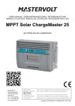
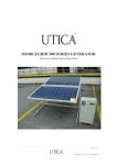
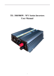
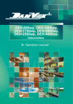
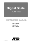
POWER CONDITIONING UNIT USER MANUAL/WARRANTY BOOK 1 "========================================================================================== DEALER / DISTRIBUTOR SEAL / SIGNATURE: PURCHASE DETAIL (DATE / INVOICE NUMBER): SERIAL NUMBER: MODEL NUMBER: OWNERS COPY: WARRANTY CARD: " DEALER / DISTRIBUTOR SEAL / SIGNATURE: PURCHASE DETAIL (DATE / INVOICE NUMBER): SERIAL NUMBER: MODEL NUMBER: MANUFACTURER COPY ( PLEASE SEND THE SIGNED COPY BACK TO US): 15 Dear Customer, Thank you for deciding in favor of PHOCOS Solar PCU. In doing so you have purchased an innovative, high quality product with unique equipment features and a high constant efficiency. This user manual contains explanations on using the PHOCOS Solar PCU.You will learn to recognize the many possibilities of the Solar Inverter. Information is provided on safety and installation. Please observe the safety precautions exactly to ensure increased safety at the operating site of the PCU. WARNING! Before installation of PCU, read and save these safety instructions. Important Safety Instructions: IMPORTANT: READ AND SAVE THIS OWNER'S GUIDE FOR FUTURE REFERENCE.This chapter contains important safety and installation instructions for the SOLAR PCU. Each time, before using the SOLAR PCU, READ ALL instructions and cautionary markings on or provided with the inverter and all appropriate sections of this guide Safety Precautions to be followed while Installation, Operation & Maintenance for PCU as High voltage is present inside unit. Incorrect installation or use may result in risk of electric shock or fire. No user serviceable parts in this unit. Do not expose the inverter to rain, snow, spray, or bilge water. This inverter is designed for indoor use only. Do not operate the inverter if it has received a sharp blow, been dropped, has cracks or openings in the enclosure including if the fuse cover has been lost, damaged, or will not close, or otherwise damaged in any other way. Do not disassemble the inverter. Internal capacitors remain charged after all power is disconnected. 14 3 Disconnect both AC and DC power from the inverter before attempting · The serial number of your product. any maintenance or cleaning or working on any circuits connected to · Information about the installation and use of the unit. the inverter. See note below. · Information about the failure and/or reason for the return. · A copy of your dated proof of purchase. Do not operate the inverter with damaged or substandard wiring. Make sure that all wiring is in good condition and is not undersized. To RMA please contact Pls check Dealer Seal for Contact number. ELECTRICAL SHOCK HAZARD Return Procedure: 1. DANGER Please ensure that your product is shipped fully insured in the original packaging or equivalent. This warranty will not apply where the product is damaged due to improper packaging. STATEMENT OF HAZARDS:Contains statements of avoidance or Strict Compliance. Failure to follow these Instructions will result in death or serious Injury. Package the unit safely, preferably using the original box and packing materials. 2. Include the following: · The RMA number supplied by Phocos clearly marked on the outside of the box. · A return address where the unit can be shipped. Post office boxes are not acceptable. · A contact telephone number where you can be reached during work hours. · A brief description of the problem. Failure to follow these instructions will result in death or serious injury NOTE: Turning off the inverter using the on/off switch on the front panel will not reduce an electrical shock hazard. FIRE AND BURN HAZARD Do not cover or obstruct the air in take vent openings and/or install in a zero-clearance compartment. Do not use transformer less battery chargers in conjunction with the Inverter due to overheating. 3. Ship the unit prepaid to the address provided by your Phocos customer service representative. Failure to follow these instructions will result in death or serious injury Out of Warranty Service: EXPLOSION HAZARD If the warranty period for your product has expired, if the unit was damaged by misuse or incorrect installation, if other conditions of the warranty have not been met, or if no dated proof of purchase is available, your product may be serviced at actual repair case only. · Charge only properly rated (such as 12V/24V ) lead-acid (GEL, AGM, Flooded,)rechargeable batteries because other battery types may explode and burst. · Do not work in the vicinity of lead-acid batteries. Batteries generate explosive gases during normal operation. See note #1. · Do not install and/or operate in compartments containing flammable materials or in locations that require ignition-protected equipment. · Failure to follow these instructions will result in death or serious injury. 4 13 · · The dated purchase receipt from the original purchase of the product at NOTES: point of sales. 1. Follow these instructions and those published by the battery manufacturer and the manufacturer of any equipment you intend to use in the vicinity of the battery. Review cautionary markings on these products and on the engine. The dated invoice or purchase receipt showing the product exchanged under warranty. 2. This inverter contains components which tend to produce arcs or sparks. This Limited Warranty does not cover normal wear and tear of the product or costs related to the removal, installation, or troubleshooting of the customer's electrical systems. This warranty does not apply to and Phocos will not be 3. Locations include any space containing gasoline-powered machinery, fuel tanks, as well as joints, fittings, or other connections between components of the fuel system responsible for any defect in or damage to: · The product if it has been misused, neglected, improperly installed, Precautions When Working With Batteries physically damaged or altered, either internally or externally, or damaged from WARNING improper use or use in an unsuitable environment; · The product if it has been subjected to fire, water, generalized corrosion, biological infestations, or input voltage that creates operating conditions NOTES: beyond the maximum or minimum limits listed in the Phocos product 1. Locate the PHOCOS SOLAR PCU unit away from batteries in a well ventilated compartment. specifications including high input voltage from generators and lightning strikes; · The product if repairs have been done to it other than by Phocos; · The product if it is used as a component part of a product expressly warranted by another manufacturer; · The product if its original identification (trade-mark, serial number) markings have been defaced, altered, or removed. Return Material Authorization Policy: Before returning a product directly to Phocos you must obtain a Return Material Authorization (RMA) number and the correct factory “Ship To” address. Products must also be shipped prepaid. Product shipments will be refused and returned at your expense if they are unauthorized, returned without an RMA number clearly marked on the outside of the shipping box, if they are shipped collect, or if they are shipped to the wrong location. When you contact Phocos to obtain service, please have your instruction manual ready for reference and be prepared to supply: 12 2. Always have someone within range of your voice or close enough to come to your aid when you work near a lead-acid battery. 3. Always have plenty of fresh water and soap nearby in case battery acid contacts skin, clothing, or eyes. 4. If battery acid contacts skin or clothing, wash immediately with soap and water. If acid enters your eye, immediately flood it with running cold water for at least twenty minutes and get medical attention immediately. 5. Use extra caution to reduce the risk or dropping a metal tool on the battery. It could spark or short circuit the battery or other electrical parts and could cause an explosion. 6. Batteries can produce a short circuit current high enough to weld a ring or metal bracelet or like to the battery terminal, causing a severe burn. 7. When removing a battery, always remove the negative terminal from the battery first for systems with grounded negative. If it is grounded positive, remove the positive terminal first. Make sure all loads connected to the battery and all accessories are off so you don't cause an arc. 5 Typical Loads Suitable for Usage:- Maintenance and Service: Ø · CFL Lamp · Incandescent Lamp · Fluorescent Lamps supply (building wiring socket outlet), components inside the PCU · Table Fan/ Ceiling Fan system are still connected to the battery and are still electrically live and · TV dangerous. · Computer To reduce risks of electric shock, disconnect all wiring before cleaning. Always maintain caution during maintenance & service. Ø Ø Even after the unit is disconnected from the Solar Panel / mains power Before carrying out any kind of servicing and/or maintenance, disconnect the battery and verify that no current is present. NOTE: Because of a policy of continuous product improvement, the specifications are subject to change without notice. CAUTION RISK OF DAMAGE TO THE INVERTER Never allow battery acid to drip on the inverter when reading gravity, or filling battery. Never place the SOLAR PCU unit directly above batteries; gases from a battery will corrode and damage the inverter. Do not place a battery on top of the inverter. Failure to follow these instructions can damage the unit and/or Damage other equipment. Installation: Overview of Installation Steps Mount the inverter. Connect the DC cables(Battery). Connect the SPV cables(Solar). Connect the AC cables(Mains). Mount the Inverter 1. Make sure that the inverter's switch is in the centre position. 2. Select an appropriate mounting location and orientation. The inverter must be oriented in under a horizontal surface. 3. Note:Any Other Loads connect to the INVERTER please check with Manufacture WARRANTY: This Limited Warranty is provided by Phocos India Solar Pvt. Ltd. and covers defects in workmanship and materials in your product. This warranty period lasts for 2 year from the date of purchase at the point of sale to you. You require proof of purchase to make warranty claims. This Limited Warranty is transferable to subsequent owners but only for the unexpired portion of the Warranty Period. Subsequent owners also require proof of purchase. Phocos will, at its option, repair or replace the defective product free of charge, provided that you notify Phocos of the product defect within the Warranty Period, and provided that Phocos through inspection establishes the existence of such a defect and that is covered by this Limited Warranty. Phocos will, at its option, use new and/or reconditioned parts in performing warranty repair and building replacement products. Phocos reserves the right to use parts or products of original or improved design in the repair or replacement. If Phocos repairs or replaces a product, its warranty continues for the remaining portion of the original warranty period. All replaced products and all parts removed from repaired products become the property of Phocos. In any warranty claim, dated proof of purchase must accompany the product and the product must not have been disassembled or modified without prior written authorization by Phocos. Proof of purchase may be in any one of the following forms: Don't connect the AC input cable before connecting the battery cable. 6 11 System Output Condition When the Battery is charged fully , System output will be automatically change over to UPS mode, and resume back only by 11.5V±0.2V/23V±0.2V when PV is available. Charging priority Battery is always charged through Solar as priority. AC Input Range INVERTER mode Grid Low cut off / Recovery Grid high cut off / Recovery : 110V AC ± 5V / 120V AC ± 5V : 270V AC ± 5V / 265V AC ±5V AC Input Range UPS mode Grid Low cut off / Recovery Grid high cut off / Recovery : 170V AC ± 5V / 180V AC ± 5V : 270V AC ± 5V / 265V AC ± 5V Protection Over Load, Phase Reversal, Over Temperature, Surge, PV Reverse Polarity Connect the DC Cables DAMAGE FROM A REVERSE POLARITY CONNECTION Ø DC power connections to the inverter must be positive to positive and negative to negative. Ø A reverse polarity connection (connecting positive to negative) can cause permanent damage to the inverter. Damage caused by a reverse polarity connection is not covered by the warranty. Failure to follow these instructions can damage the unit and/or damage other equipment. Ø Make sure the inverter's ON/OFF switch is in the centre position. Ø Inverter's positive [RED] DC Cable to properly connected terminal of the battery. Ø Inverter's Negative [Black] DC Cable to properly connected Negative terminal Of the battery. IP20 Operating temperature : 0°C to + 55°C Relative Humidity : 0 to 90% Ø Do not install PCU near flammable materials like plywood, chemicals, gasoline, etc. Weight (Approx) 6.5Kg Ø Mechanical Dimension Cooling Always ensure you connect the PCU system to an earthed shockproof socket outlet. Thermostatically controlled cooling fan Ø Ensure proper Tools / connections for Solar Input to PCU and AC Output from PCU. Ø Please make sure the battery inter connections (Series Parallel in case of need) were done properly as per system voltage requirement. Ø Connect the Battery, Solar Panel and AC mains as per the instruction given in Pic Rear View. Ø Please make sure the switch in the front panel was in centre position. Ø Connect Battery terminals with battery by ensuring correct polarity (Wrong Polarity connection will lead to permanent failure of the product) Ø Connect PV Terminals with solar panel by ensuring correct polarity (Wrong Polarity connection will lead to permanent failure of the product) Ø Connect the loads with PCU with Output Socket provided for AC Output, Kindly make sure the AC socket used to draw AC power suits the existing AC socket and free from damage. Displays Power Saving Recovery Enclosure Rating Environmental Battery Voltage, Load Level, UPS ON, Mains ON, MPPT ON, Battery Full, Charger on 3 Seconds 110mm X 280mm X 390mm ( H X W X L ) CHARGE CONTROLLER SPECIFICATION: Type MPPT 84V DC @ 12/24V PWM Max solar Input Voltage (Voc) 110VDC @ 48V 12V/24V/48V Auto Nominal Voltage recognition 40V DC Solar input Max VMP/Min VMP 90VMP/66VMP(48V) 66VMP/38VMP(24V) 55VMP/18VMP(12V) 36VMP/21VMP Max PV Input Power Charging Current (Imax) Efficiency 400Wp(12V)*/1000Wp(24V)* 1500Wp* (48V) 30A(at 12V system) 40A(at 24V system)* 30A(at 48V system) 97% Peak** 12V/ 24V* 360Wp*/1000Wp* 30A(at 12V system) 40A(at 24V system)* 92% Peak *Note : Manufacturer holds the rights to change the specifications without any prior notice. **Tracking 10 7 positive Ø Switch on the PCU by operating switch in front panel to Inverter Mode and ensure the Display as in Pic 1. Ø Connect AC Mains cable with AC Grid source and ensure the display as in pic 2 and please do not feed the output of the PCU as the input to PCU again as it will lead to malfunction of the unit. NOTE: In the case generator AC power ensure that the frequency and voltage regulation within the limit otherwise PCU will lead to malfunction. ** Ø UPS ON LOAD MPPT ON BAT – XX.X V MAINS ON CHARGER ON PIC 1 MPPT ON BAT – XX.X V PIC - 2 ** XX.X V INDICATES THE BATTERY VOLTAGE LEVEL AS PER ACTUAL. £ £ £ INDICATES THE CONNECTED LOAD CAPACITY Operation: ð Do not disconnect Solar Panel Input cable / mains cable of the PCU system and also the power socket outlet during operations since this would nullify the grounding of PCU system and all connected loads. ð The PCU has its own internal power source (batteries). The output terminals may be electrically live even when the PCU is not connected to the Solar Panel / AC supply. Hence handle with caution. UPS BYPASS INVERTER UPS ON LOAD ð In case of any Error observed please note down the error code which will get generated and displayed in front panel display which will help the service engineers for a quick fix. MPPT ON BAT – XX . X V Technical Specification: Nominal output power Picture: 1 PV Panel 450VA 650VA 800VA 1400VA 2000VA 350W 500W 650W Battery Voltage 12V DC Input AVR range 110V AC to 275V AC ± 5 V AC Output frequency 50Hz ± 1% 1000W 1600W 24V DC 24V/48V DC Output wave form Mains Cable FUSE Pure Sine Wave Output voltage in INVERTER 225V AC ± 5%. Output voltage in MAINS Same as Input Voltage. AC OUTPUT (+ve) solar I/P (-ve) BATTERY I/P (+ve) AC MAINS I/P Back View 8 MPPT / PWM AC Charging Current 2A to 10A auto programmed Inverter efficiency >85% Power Factor 0.8 Typical transfer time < 15ms in UPS mode. / < 40 ms in INVERTER mode. Battery LVD Cut off 10.8V ± 0.2V 21.6V ± 0.2V 43.2V± 0.2V Load Reconnection 12.6V ± 0.2V 25.2V ± 0.2V 50.4V± 0.2V (-ve) (+ve) Picture: 2 Solar Charge controller (-ve) 9