1
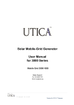
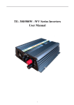
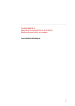
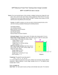
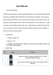
MOBILEGRID 500 SERIES GENERATOR Powered by 400Wp Photovoltaic Panels 1|Page Produced for UTICA™ Singapore User’s manual Contents 1 Introduction .................................................................................................................................... 2 1.1 Overview ............................................................................................................................. 2 1.2 Working Principle ............................................................................................................... 3 1.3 Technical Features ............................................................................................................... 3 1.4 Matters Need Attention ....................................................................................................... 4 1.5 Installation condition........................................................................................................... 5 1.6 The installation and wiring of the inverter .......................................................................... 5 2 Operation of Inverter ...................................................................................................................... 6 2.1 Introduction of Panel........................................................................................................... 6 2.2 Control Indicator Panel ....................................................................................................... 6 2.3 Operation Procedure ........................................................................................................... 7 2.4 Technical Management ....................................................................................................... 8 3 Technical Specification .................................................................................................................. 9 3.1 Technical Specification of Single Phase Output ................................................................. 9 1. Introduction 1.1 Overview UTICA™ develops and produces the MobileGrid Generator, an alternative energy system for residential, commercial and industrial buildings. The MobileGrid 500 series generator transforms the direct current generated by solar into alternating current. This current is good for general lightings, off-grid/ remote areas, on ships, hospitals, schools and military. Mobile-Grid Generator is affordable, reliable and effective. 2|Page Produced for UTICA™ Singapore 1.2 Working Principle Under normal sunlight, the Mobile-Grid Generator’s photovoltaic cells convert sunlight into electric currents, which transfer the energy into storage batteries. The entire process by control circuit is automated. The power controller will automatically adjust the charging/ discharging current parameters and performance. Inverter Resource s of solar Solar charging control Output Batterie s set Micro-process control circuit High Freq. Numerical PV Controller & Inverter The PV inverter transfers the DC voltage from the storage batteries back to AC voltage which is required during the functions of electrical appliances. We have integrated advance micro-processor UTM68HC908MR32CFU to control and manage the system more efficiently. 1.3 Technical Features The PV inverter is operated by numerical signal processing that uses the micro-processor as the control system. The following are the characteristics. 1) The PV inverter uses IGBT which is quickly switched and little power loss as its power components. At the same time, it applies high-frequency separation technology. So the inverter has many advantages, such as, little distortion of output waveform, low noise, good dynamic characteristic and high-efficient inverse. 2) The controller adopts the fast speed micro-processer UTM68HC908MR32CFU as the core CPU. It contains the features as voltage protection of output overload, over output, low output acts quickly, the ability of anti-interference is strong, and the accuracy of stabilized voltage is high and so on. 3) Output short-circuit protection adopts dual protection that includes output circuit detect protection and module circuit current detect protection. It largely enhances the reliability of short-circuit protection. 4) There is a filtering device in the output of inverter. It makes the load included in the PV inverter free from the interference of high-frequency harmonious wave. 3|Page Produced for UTICA™ Singapore 5) The part of display is the combination of LCD and LED. You can learn the operation status of the PV inverter clearly through the panels of machine. The LCD has the following functions: output voltage of the PV inverter, inverse frequency, the proportion of the load power, batteries voltage and other three parameters. Meanwhile, if the PV inverter is in the inverse status, if the load included is overload, if the battery is under-voltage and so on, all of this, you can see from the LED indication light. 6) It has all kinds of alarming function, for example, battery under-voltage and overvoltage alarm, system/ PV inverter malfunction alarm, overload alarm, over-temp. alarm and so on. 7) The charging mode of solar to storage battery is the mixture of the type of on/off and the type of impulse-width modulation. It makes full use of the limited solar energy and can extend the service life of the storage batteries at the same time. 8) There are anti-surge SPD and lightning MCB protection devices in the charging control system. 1.4 Matters Need Attention This equipment has been manufactured in accordance with the state of the art and general safetyengineering procedures. Please note the following. 1) Please read the operation manual thoroughly and follow the instructions. 2) Must ensure air can follow freely through the air vents without obstruction. 3) Do not carry out any alterations or modifications to the machine. 4) Please keep the PV inverter clean and cool. 5) All cables must be firmly attached and insulated. 6) If malfunctions, please reboot the system follow restart procedure slowly. 7) Please store the operation manual for using in the future. 8) The machine shall have an earth-connection system to ensure the safety. 9) Have to charge a whole day under sunshine before the first time using. 10) Under normal sunlight, there is no need to startup, the machine is automatic charging. 11) In the daytime and under the normal sunlight, the PV inverter also can be used, but the load added shall not beyond the supply of solar energy input. 12) Avoid using the PV inverter under thundery and rainy days. 13) In order to avoid the damage to the machine, please do not open the safety cover. 4|Page Produced for UTICA™ Singapore 1.5 Installation condition Ensure an appropriate indoor environment when installation. 1) No dust. 2) Appropriate temperature. 3) Related humidity complies with the specification. 4) No caustic gas, such as, steam. 5) No inflammable and explosive nearby. 6) With power supply complies with the safety requirement. 7) The distance between the back and sides of the machine and wall or some other things shall be wider than 50 cm. 8) Do not put anything on the top/front of the machine as there must be enough operation space in the front of the machine. 9) The cabling path of the power wires shall be clear from other materials. 1.6 The installation and wiring of PV inverter Matters need attention 1) Please follow the electricians rules when execution. 2) Finish the earth-connection work, if do not connect to the “earth-connection” system, the inverter cannot operate normally. 3) Use the multi-meter to measure if the input voltage is the correct voltage. 4) Avoid working charged, and pay attention to safety execution. 5) Take off the cover which covers the terminal row. 6) Butt joint the input and output cable correctly according to the wiring marks of the terminal row, and wrap with appropriate insulated tape and then lock. 7) After finishing wiring, reinstall the cover of terminal row, and then start the machine. The schematic diagram of the wiring terminal of single phase output inverter 5|Page Produced for UTICA™ Singapore 2 Operation of Inverter 2.1 Introduction of Panel The Full View of the Machine 2.2 Control Indicator Panel 1) Input indicator (green): indication of solar input; 2) Charge indicator (yellow): indication of solar charging for battery; 3) Inverse indicator (green): indication of supplying output of inverter; 4) Battery indicator (yellow): It shows the battery provides energy to load; 5) Malfunction indicator (red): indication of inverter malfunction; 6) LCD screen: displays the digital signal, such as, AC output voltage, output frequency, output power, state of inverter and so on; 7) The option key on the LCD screen: press the key, it will display all working parameters of inverter circularly; 8) The key to startup of the PV inverter: press this key, you can start the machine; press this key, you can stop the noise when the buzzer makes a lot of noise intermittently (when battery under-voltage and overload, press this key is invalid.) 9) The key to shut down of the inverter: the machine can be shut down if you press the key for 4 seconds. 6|Page Produced for UTICA™ Singapore ⑥ ① ② ③ ④ ⑤ ⑦ ⑨ ⑧ The contents of the LCD screen displays as follow. (1)OUTPUT VOLTAGE (2)OUTPUT FREQUENCY (3)BATTERY VOLTAGE (4)OUTPUT POWER 2.3 Operation Procedure The machine of this system is easy to operate. The system can run normally if you operate it as following correct steps. Confirm there is no load connected to the inverter output. Check that if the input power of the inverter is normal or not. Press the “ ON” key on the down panel, then the power light shines and the malfunction indicator is on(the inverter is doing self-check), after the malfunction indicator is off, press the “ ON” key again and last for 3 s, the buzzer of the inverter makes noise intermittently, it shows the inverter begins to run. The output indicator will be on after 20 s, it tells us the inverter is in normal operating. The inverter startup, the load can be operated (attention that the load added shall not beyond the rated output power of inverter. ) In order to wipe out the alarming of the buzzer, the machine can be in noise-hidden state(it does not work when the battery is under-voltage and overload.) if you want to recover the alarming of inverter, you only need to press the “ ON” key for another time. If you want to stop using the inverter, only need to press the “OFF” key(attention that please close down the inverter when there is no load on the output terminal of the inverter, it also can save energy of the storage battery.) 7|Page Produced for UTICA™ Singapore 2.4 Technical Management The normal alarming of the buzzer of inverter is screaming once every 5 s. If the screaming becomes quickly or longer duration, it could be that the inverter is abnormal working. In this situation, please following the instruction below. (1) The output of inverter is normal, but the screaming of buzzer is once every 1 s. The reason why buzzer screams once every 1 s is the voltage of battery is too low, please handle it as follow. 1. Because the sun power is not enough, the storage battery is not full charged. Advise the inverter stops to supply to load, and do not use the inverter until the storage battery is full charged. 2. When there is sunlight and the terminal voltage of battery is normal, however, once the inverter supplies to load, the voltage of the storage battery lower down quickly. This shows that the internal resistance of battery has became larger, recommend to change the storage battery. 3. The voltage of battery is too low, it cannot charge when there is not enough sunlight, suggest to adjust your charging control board. (2) The output of inverter is normal, but the screaming of buzzer is twice every 1 s. It is caused by overload, so you can emphasis on checking if the loads are too much. Advise to remove some unimportant load. If the buzzer continues to scream twice every 1s, the only thing you can do is to change the CPU board. (3) The inverter works normally, but after a while, it screams for a while and without output, and it will recover automatically after several minutes. It is caused by over-temperature of the power module of control system of the inverter. You should check the fan, and meanwhile check that if the air outlet of the fan blocks or not, or you can remove some unimportant load. (4) The inverter cannot be started by pressing the “ON” key. This phenomenon is always due to the voltage of storage battery is too low, you should full charge the storage battery and then apply the inverter. (5) The buzzer always screams and without output. This phenomenon is due to malfunction in the control system of the inverter, you should contact our maintenance professional to fix it. 8|Page Produced for UTICA™ Singapore 3 Technical Data 3.1 Technical Specification of Single Phase Output MobileGrid Generator 500 Series Nominal Capacity 600VA/480W DC Input Model Solar Voltage 24V~50V Solar Current 0.5A~10A Battery Voltage 24VDC±15% (200AH) Output Voltage 220VAC±2% Output Frequency 50HZ±0.5 Output Waveform Pure Sine Wave THD Distortion ≤3% linear load;non-linear load<5% Response Time <10ms Efficiency of Inverter ≥93% linear load Overload Capability 120% overload 30s Operation Temperature -10~50℃ Cooling Forced Air Ventilation Related Humidity 0%-90%(no condensation) LCD Indication Function LED Protection Function Inverter output voltage and output frequency, battery voltage value, load volume and so on Solar input(green), solar charge(yellow), inverter output(green), battery supply(yellow), overload/ malfunction(red) Overload, short-circuit, under-voltage, overvoltage, over-temp., Appearance Size 长×宽×高(mm) Input & Output Device Wiring terminal row Weight(kg) 25kg (without batteries) 250X450X855 9|Page Produced for UTICA™ Singapore