1
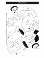
Owner's Manual
CRAFTSMAN°
ROTARY LAWN MOWER
160cc or 190cc Honda Engine
Power-Propelled
22" Multi-Cut
Model No.
917.376543
• Espa_ol,
p. 20
CAUTION'.
Read and follow all
Safety Rules and Instructions
before operating this equipment
Sears, Roebuck and Co., Hoffman Estates, IL 60179 U.S.A.
Visit our Craftsman website: www.sears.com/craftsman
Maintenance ......................................
Service and Adjustments ...................
Storage ..............................................
Troubleshooting .................................
Repair Parts .......................................
Sears Service .......................... Back
Warranty ...................................................
2
Safety Rules ..........................................
2-4
Product Specifications .............................. 4
Assembly / Pre-Operation ........................ 6
Operation .............................................
7-11
Maintenance Schedule ........................... 12
2-YEAR
FULL WARRANTY
ON CRAFTSMAN
12-15
16-17
17-18
18-19
38-53
Cover
LAWN MOWER
If this Craftsman Lawn Mower fails due to manufacturer defects in material or
workmanship within two years from the date of purchase, return it to any Sears store,
Parts & Repair Center or other Craftsman outlet for free repair (or replacement if repair
proves impossible).
This warranty applies for only 90 days from the date of purchase if this Lawn Mower is
ever used for commercial or rental purposes.
This warranty does not cover:
•
Expendable items that become worn during normal use, such as rotary mower
blades, blade adapters, belts, air cleaners and spark plug.
.
Repairs necessary because of operator abuse or negligence, including bent
crackshafts and the failure to assemble, operate or maintain this Lawn Mower
according to all supplied product instructions.
This warranty applies only while this product is used in the United States.
This warranty gives you specific legal rights, and you may also have other rights which
vary from state to state.
Sears,
Roebuck
and Co., Hoffman
Estates,
IL 60179
IMPORTANT:
This cutting machine is capable of amputating hands and feet and throwing objects. Failure to observe the following safety instructions could result in serious
injury or death.
_i, Look for this symbol to point out important safety precautions. It means
CAUTION!!!
BECOME ALERT!!!
YOUR SAFETY IS INVOLVED.
_I,WARNING" Battery posts, terminals and
related accessories contain lead and lead
compounds, chemicals known to the State
of California to cause cancer and birth
defects or other reproductive harm. Wash
hands after handling.
_I, WARNING:
In order to prevent accidental starting when setting up, transporting, adjusting or making repairs,
always disconnect spark plug wire and
place wire where it cannot come in contact
with plug.
_i, CAUTION:
Muffler and other engine
parts become extremely hot during
operation and remain hot after engine has
stopped. To avoid severe burns on contact,
stay away from these areas.
&WARNING"
Engine exhaust, some of its
constituents, and certain vehicle components
contain or emit chemicals known to the State
of California to cause cancer and birth defects
or other reproductive harm.
2
I. GENERAL
OPERATION
• Read, understand, and follow all
instructions on the machine and in the
manual(s) before starting. Be thoroughly
familiar with the controls and the proper
use of the machine before starting.
• Do not put hands or feet near or under
rotating parts. Keep clear of the discharge opening at all times.
• Only allow responsible individuals, who
are familiar with the instructions, to operate the machine.
• Clear the area of objects such as rocks,
toys, wire, bones, sticks, etc., which
could be picked up and thrown by blade.
• Be sure the area is clear of other people
before mowing. Stop machine if anyone
enters the area.
• Do not operate the mower when barefoot or wearing open sandals. Always
wear substantial foot wear.
• Do not pull mower backwards unless
absolutely necessary. Always look down
and behind before and while moving
backwards.
• Never direct discharged material toward
anyone. Avoid discharging material
against a wall or obstruction.
Material
may richochet back toward the operator. Stop the blade when crossing gravel
surfaces.
• Do not operate the mower without
proper guards, plates, grass catcher or
other safety protective devices in place.
• See manufacturer's instructions for
proper operation and installation of
accessories. Only use accessories approved by the manufacturer.
• Stop the blade(s) when crossing gravel
drives, walks, or roads.
• Stop the engine (motor) whenever you
leave the equipment, before cleaning the
mower or unclogging the chute.
• Shut the engine (motor) off and wait until
the blade comes to complete stop before
removing grass catcher.
• Mow only in daylight or good artificial
light.
• Do not operate the machine while under
the influence of alcohol or drugs.
• Never operate machine in wet grass.
Always be sure of your footing: keep a
firm hold on the handle; walk, never run.
• Disengage the self-propelled mechanism or drive clutch on mowers so
equipped before starting the engine.
• If the equipment should start to vibrate
abnormally, stop the engine (motor) and
check immediately for the cause. Vibration is generally a warning of trouble.
. Always wear safety goggles or safety
glasses with side shields when operating
mower.
Ii. SLOPE
OPERATION
Slopes are a major factor related to slip &
fa!l accidents which can result in severe injury. All slopes require extra caution. If you
feel uneasy on a slope, do not mow it.
DO:
• Mow across the face of slopes: never
up and down. Exercise extreme caution
when changing direction on slopes.
• Remove obstacles such as rocks, tree
limbs, etc.
• Watch for holes, ruts, or bumps. Tall
grass can hide obstacles.
DO NOT:
• Do not trim near drop-offs, ditches or
embankments. The operator could lose
footing or balance.
• Do not trim excessively steep slopes.
• Do not mow on wet grass. Reduced footing could cause slipping.
Iii. CHILDREN
Tragic accidents can occur if the operator
is not alert to the presence of children.
Children are often attracted to the machine
and the mowing activity. Never assume
that children will remain where you last
saw them.
• Keep children out of the trimming area
and under the watchful care of another
responsible adult.
• Be alert and turn machine off if children
enter the area.
• Before and while walking backwards,
look behind and down for small children.
• Never allow children to operate the machine.
• Use extra care when approaching blind
corners, shrubs, trees, or other objects
that may obscure vision.
IV. SAFE HANDLING
OF GASOLINE
Use extreme care in handling gasoline.
Gasoline is extremely flammable and the
vapors are explosive.
• Extinguish all cigarettes, cigars, pipes
and other sources of ignition.
• Use only an approved container.
• Never remove gas cap or add fuel with
the engine running. Allow engine to cool
before refueling.
• Never refuel the machine indoors.
• Never store the machine or fue! container where there is an open flame, spark
or pilot light such as a water heater or on
other appliances.
3
• Never fill containers inside a vehicle, on
a truck or trailer bed with a plastic liner.
Always place containers on the ground
away from your vehicle before filling.
• Remove gas-powered equipment from
the truck or trailer and refuel it on the
ground. If this is not possible, then
refuel such equipment with a portable
container, rather than from a gasoline
dispenser nozzle.
• Keep the nozzle in contact with the rim
of the fuel tank or container opening at
all times until fueling is complete. Do
not use a nozzle lock-open device.
• If fuel is spilled on clothing, change
clothing immediately.
• Never overfill fuel tank. Replace gas
cap and tighten securely.
V. GENERAL
• Keep nuts and bolts, especially blade
attachment bolts, tight and keep equipment in good condition.
• Never tamper with safety devices. Check
their proper operation regularly.
• Keep machine free of grass, leaves, or
other debris build-up. Clean oil or fuel
spillage. Allow machine to cool before
storing.
• Stop and inspect the equipment if you
strike an object. Repair, if necessary,
before restarting.
• Never attempt to make wheel height
adjustments while the engine is running.
• Grass catcher components are subject
to wear, damage, and deterioration,
which could expose moving parts or
allow objects to be thrown. Frequently
check components and replace with
manufacturer's recommended parts,
when necessary.
• Mower blades are sharp and can cut.
Wrap the blade(s) or wear gloves, and
use extra caution when servicing them.
• Do not change the engine governor setting or overspeed the engine.
• Maintain or replace safety and instruction labels, as necessary.
SERVICE
• Never run a machine inside a closed
area.
Never make adjustments or repairs with
the engine (motor) running. Disconnect
the spark plug wire, and keep the wire
away from the plug to prevent accidental
starting.
&WARNING:
This lawn mower is equipped with an internal combustion engine and
should not be used on or near any unimproved forest-covered, brush-covered or
grass-covered land unless the engine's exhaust system is equipped with a spark
arrester meeting applicable local or state laws (if any). If a spark arrester is used, it
should be maintained in effective working order by the operator.
In the state of California the above is required by law (Section 4442 of the California
Public Resources Code). Other states may have similar laws. Federal laws apply on
federal lands. A spark arrester for the muffler is available through your nearest Sears
Parts & Repair Center (See the REPAIR PARTS section of this manual).
Serial Number:
Date of Purchase:
Gasoline Capacity / Type:
1.0 Quarts (Unleaded
Oil Capacity:
18.5 Ounces
Oil Type (API SG-SL):
SAE 30 (above 32°F) or SAE 10W-30
Spark Plug (Gap:
NGK BPR6ES
Valve Clearance
.030")
(+ 0.04 mm):
Blade Bolt Torque:
Intake: 0.015 mm;
Regular)
Exhaust: 0.020 mm
35-40 ft. Ibs.
• The model and serial numbers wil! be found on a decal on the rear of the lawn mower
housing. Record both serial number and date of purchase in space provided above.
4
Repair Protection
Congratulations on making a smart purchase. Your new Craftsman® product is
designed and manufactured for years of
dependable operation. But like all products, it may require repair from time to
time. That's when having a Repair Protection Agreement can save you money and
aggravation.
Agreements
•
Fast help by phone- phone support from a Sears representative on
products requiring in-home repair, plus
convenient repair scheduling.
Once you purchase the Agreement, a
simple phone call is all that it takes for you
to schedule service. You can call anytime
day or night, or schedule a service appointment online.
Sears has over 12,000 professional repair
specialists, who have access to over 4.5
million quality parts and accessories.
That's the kind of professionalism you can
count on to help prolong the life of your
new purchase for years to come. Purchase
your Repair Protection Agreement today!
Some limitations and exclusions
apply.
For prices and additional
information
call 1=800=827=6655.
Purchase a Repair Protection Agreement
now and protect yourself from unexpected
hassle and expense.
Here's what's included in the Agreement:
• Expert service by our 12,000 profesional repair specialists.
• Unlimited service and no charge for
parts and labor on all covered repairs.
• Product replacement
if your covered
product can't be fixed.
• Discount of 10% from regular price of
service and service-related parts not
covered by the agreement; also, 10%
off regular price of preventive maintenance check.
Sears
Installation
Service
For Sears professional installation of home
appliances, garage door openers, water
heaters, and other major home items, in
the U.S.A. call 1-800-4-MY-HOME®.
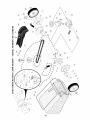
These accessories were available when this lawn mower was produced. They are not
shipped with your mower. They are also available at most Sears retail outlets and
service centers. Some of these accessories may not apply to your lawn mower.
LAWN MOWER
PERFORMANCE
CLIPPING
DEFLECTORS
FOR
REAR DISCHARGE
STABILIZER
CANS
GAS
LAWN MOWERS
GRASS CATCHERS
FOR
REAR DISCHARGE
LAWN MOWERS
LAWN MOWER
GRASS CATCHERS
FOR
SIDE DISCHARGE
LAWN MOWERS
MAINTENANCE
MUFFLERS
BELTS
AIR FILTERS
BLADES
BLADE ADAPTERS
5
SPARK
WHEELS
PLUGS
ENGINE OIL
Read these instructions and this manual in its entirety before you attempt to assemble
or operate your new lawn mower.
IMPORTANT: This lawn mower is shipped WITHOUT OIL OR GASOLINE in the engine.
Your new lawn mower has been assembled at the factory with the exception of those parts
left unassembled for shipping purposes. To ensure safe and proper operation of your lawn
mower, all parts and hardware you assemble must be tightened securely. Use the correct
tools as necessary to ensure proper tightness. All parts such as nuts, washers, bolts, etc.,
necessary to complete the assembly have been placed in the parts bag.
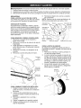
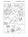
Handle
bracket
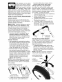
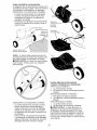
TO REMOVE MOWER FROM CARTON
1. Remove loose parts includedwith mower.
2. Cut down two end corners of carton
and lay end panel down flat.
3. Remove all packing materials except
padding between upper and lower
handle and padding holding operator
presence control bar to upper handle.
4. Roll lawn mower out of carton and
check carton thoroughly for additional
loose parts.
Knob
,-_
Bolt
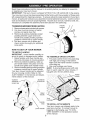
NOW TO SET UP YOUR MOWER
TO UNFOLD
HANDLE
iMPORTANT:
Unfold handle carefully so
as not to pinch or damage control cables.
1. Raise handles unti! lower handle section locks into place in mowing position.
2. Remove protective padding, raise upper handle section into place on lower
handle and tighten both handle knobs.
3. Remove handle padding holding operator
presence control bar to upper handle.
Your lawn mower handle can be adjusted
for your mowing comfort. Refer to "ADJUST HANDLE" in the Service and Adjustments section of this manual.
Operator
I:
control bar
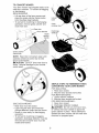
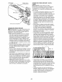
TO ASSEMBLE
GRASS CATCHER
1. Put grass catcher frame into grass bag
with rigid part of bag on the bottom.
Make sure the frame handle is outside
of the bag top.
2. Slip vinyl bindings over frame.
NOTE: If vinyl bindings are too stiff, hold
them in warm water for a few minutes. If
bag gets wet, let it dry before using.
MOWING
POSITION
UP
Vinyl
bindings
Handle
knob
Frame
opening
TO iNSTALL ATTACHMENTS
Your lawn mower was shipped ready to be
used as a mulcher. To convert mower to
bagging or discharging, see "TO CONVERT MOWER" in the Operation section
of this manual.
Lower handle
6
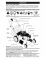
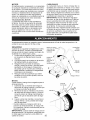
KNOW YOUR LAWN
MOWER
READ THIS OWNER'S MANUAL AND ALL SAFETY RULES BEFORE OPERATING
YOUR LAWN MOWER. Compare the illustrations with your lawn mower to familiarize
yourself with the location of various controls and adjustments.
Save this manual for
future reference.
These symbols may appear on your lawn mower
product. Learn and understand their meaning.
CAUTION
OR WARNING
ENGINE
ON
ENGINE
OFF
FAST
SLOW
or in literature supplied
CHOKE
FUEL
OIL
with the
DANGER, KEEP HANDS
AND FEET AWAY
Operator presence control bar
Drive control levers
Handle knobs
Gasoline filler cap
Fuel valve lever
Starter
handle
plug
Grass
catcher
Air filter
Wheel adjuster
(on each wheel)
Engine oil cap
with dipstick
Muffler
_
J
Mulcher door
Drive cover
Housing
IMPORTANT: This lawn mower is shipped
WITHOUT OIL OR GASOLINE in the engine.
MEETS CPSC SAFETY REQUIREMENTS
Sears rotary walk-behind power lawn mowers conform to the safety standards of the
American National Standards Institute and the U.S. Consumer Product Safety Commission. _I,WARNING: The blade turns when the engine is running.
Operator presence control bar - must
be held down to the handle to start the
engine. Release to stop the engine.
Starter handle - used for starting engine,
Mulcher door - allows conversion to
discharging or bagging operation.
Drive control levers - used to engage
power-propelled forward motion of mower.
7
handle to lift the front wheels off the
ground while turning lawn mower.
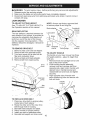
DRIVE CONTROL ADJUSTMENT
The operation of any lawn
SAFETVG'ASSES
mower can result in foreign
objects thrown into the eyes,
which can result in severe
eye damage. Always wear
safety glasses or eye shields while operating your lawn mower or performing any
adjustments or repairs. We recommend a
standard safety glasses orwide vision safety
mask worn over spectacles.
Over time, the drive control system may
become "loose", resulting in decreased
speed. There is a turnbuckle on the drive
control housing to increase tension on the
drive cable. Proceed as follows:
1. Turn unit off and disconnect spark plug
wire from spark plug.
2. Rotate turnbuckle on drive control to
increase drive speed.
3. Operate mower to test drive speed.
Readjust as required.
4. If condition fails to improve after the
above steps (forward speed remains
the same), your drive belt is worn and
should be replaced.
HOW TO USE YOUR LAWN MOWER
ENGINE SPEED
Engine speed was set at the factory for
optimum performance. It is not adjustable.
ENGINE ZONE CONTROL
_k,CAUTION:
Federal regulations require
an engine control to be installed on this
lawn mower in order to minimize the risk
of blade contact injury. Do not under
any circumstances attempt to defeat the
function of the operator control. The blade
turns when the engine is running.
• Your lawn mower is equipped with an
operator presence control bar which
requires the operator to be positioned
behind the lawn mower handle to start
and operate the lawn mower.
DRIVE CONTROL
ustment
turnbuckle
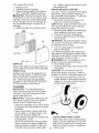
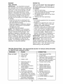
TO ADJUST CUTTING HEIGHT
Raise wheels for low cut and lower wheels
for high cut, adjust cutting height to suit
your requirements. Medium position is
best for most lawns.
• To change cutting height, pull up on
adjuster lever, move wheel up or down
to suit your requirements and release
adjuster lever. Be sure all wheels are in
the same setting.
NOTE: Adjuster is properly positioned
when lever inserts into hole in plate.
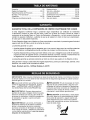
. Self-propelling is controlled by holding
the operator presence control bar down
to the handle and pulling either drive
control lever rearward to the handle.
The further toward the handle a lever is
pulled, the faster the unit will travel.
. Forward motion will stop when either
the operator presence control bar or a
drive control lever are released. To stop
forward motion without stopping engine,
release a drive control lever only. Hold
operator presence control bar down
against handle to continue mowing
without self-propelling.
NOTE: If after releasing the drive control
the mower will not roll backwards, push
the mower forward slightly to disengage
drive wheels.
LEVER BACKWARD
TO LOWER MOWER
Lever
LEVER
FORWARD
TO RAISE MOWER
Plate
Operator presence control bar
Drive
control
levers
TO ENGAGE
DRIVE CONTROL
DRIVE CONTROL
DISENGAGED
• To keep drive control engaged when
turning corners, push down on the
8
TO CONVERT
MOWER
I
Your lawn mower was shipped ready to be
used as a mulcher. To convert to bagging
or discharging:
REAR BAGGING
• Lift rear door of the lawn mower and
place the grass catcher frame hooks
onto the grass bag brackets.
• To convert to mulching or discharging
operation, remove grass catcher and
close rear door.
\
\
Unlock
latch
Open
mulcher door
I
I
door
Discharge
deflector
bracket
Grass
catcher
handle
Grass catcher
frame hook
\
/
NOTE: Rear door will remain open until
operator presence control bar is held
down to the handle.
ACAUTION:
Do NOT force rear door to
close. Serious damage to your mower
could result.
SIMPLE STEPS TO REMEMBER WHEN
CONVERTING YOUR LAWN MOWER
FOR MULCHING 1. Rear door closed.
2. Mulcher door closed and locked.
FOR REAR BAGGING 1. Grass catcher installed.
2. Mulcher door closed and locked.
FOR SIDE DISCHARGING 1. Rear door closed.
2. Discharge deflector installed.
ACAUTION:
Do not run your lawn mower without rear door closed or approved
grass catcher in place. Never attempt to
operate the lawn mower with the rear door
removed or propped open.
SIDE DISCHARGING
• Rear door must be closed.
• Open mulcher door and install discharge deflector under door as shown.
• Mower is now ready for discharging
operation.
• To convert to mulching or bagging
operation, discharge deflector must be
removed and mulcher door must be
closed and locked.
9
TO EMPTY GRASS CATCHER
ADD GASOLINE
• Fill fuel tank to bottom of tank filler neck.
Do not overfill. Use fresh, clean, regular
unleaded gasoline with a minimum of
87 octane. Do not mix oil with gasoline.
Purchase fuel in quantities that can be
used within 30 days to assure fuel freshness.
• i, CAUTION: Wipe off any spilled oil or
fuel. Do not store, spill or use gasoline
near an open flame.
,A CAUTION: Alcohol blended fuels
(called gasohol or using ethanol or methanol) can attract moisture which leads to
separation and formation of acids during
storage. Acidic gas can damage the fuel
system of an engine while in storage. To
avoid engine problems, the fuel system
should be emptied before storage of 30
days or longer. Empty the gas tank, start
the engine and let it run until the fuel lines
and carburetor are empty. Use fresh fuel
next season. See Storage Instructions for
additional information.
Never use engine
or carburetor cleaner products in the fuel
tank or permanent damage may occur.
1. Lift up on grass catcher using the
frame handle.
2. Remove grass catcher with clippings
from under lawn mower handle.
3. Empty clippings from bag using both
frame handle and bag handle.
NOTE: Do not drag the bag when emptying; it will cause unnecessary wear.
Grass
catcher
frame
BEFORE
STARTING
ENGINE
ADD OIL
Your lawnmower is shipped without oil in
the engine. For type and grade of oil to
use, see "ENGINE" in the Maintenance
section of this manual.
_i, CAUTION: DO NOT overfill engine with
oil, or it will smoke on startup.
1. Be sure lawnmower is level.
2. Remove oil fill cap/dipstick from oil fill
spout.
3. You recieve a container of oil with the
unit. Slowly pour the entire container
down the oil fill spout into the engine.
4. Insert and tighten oil fill cap/dipstick.
IMPORTANT:
• Check oil level before each use. Add oil
if needed. Fill to full line on dipstick.
• Change the oil after every 25 hours of
operation or each season. You may
need to change the oil more often
under dusty, dirty conditions. See "TO
CHANGE ENGINE OIL" in the Maintenance section of this manual.
Oil fill cap /
di
Upper
mark
Lowe
mark
TO STOP
ENGINE
• To stop engine, release operator presence control bar. Wait until blade and
all moving parts have stopped and turn
fuel valve to OFF position if you do not
intend to restart the engine soon.
TO START
ENGINE
NOTE: Due to protective coatings on the
engine, a small amount of smoke may be
present during the initial use of the product
and should be considered normal.
1. Be sure fuel valve is in the ON position.
2. Move choke lever to ON (1',,I)position.
3. Hold operator presence control bar
down to the handle and pull starter
handle quickly. Do not allow starter
rope to snap back.
NOTE: The choke lever automatically
begins moving to the OFF position when
operator presence control bar is held
down to handle.
Gasoline
filler cap
10
MULCHING
lever
OFF
MOWING
TiPS
IMPORTANT:
For best performance,
keep mower housing free of built-up
grass and trash. See "CLEANING" in the
Maintenance section of this manual.
• The special mulching blade will recut
the grass clippings many times and
reduce them in size so that as they fall
onto the lawn they will disperse into
the grass and not be noticed. Also, the
mulched grass will biodegrade quickly
to provide nutrients for the lawn. Always
mulch with your highest engine (blade)
speed as this will provide the best recutting action of the blades.
• Avoid cutting your lawn when it is wet.
Wet grass tends to form clumps and
interferes with the mulching action. The
best time to mow your lawn is the early
afternoon. At this time the grass has
dried, yet the newly cut area will not be
exposed to direct sunlight.
• For best results, adjust the lawn mower
cutting height so that the lawn mower
cuts off only the top one-third of the
grass blades. If the lawn is overgrown it
will be necessary to raise the height of
cut to reduce pushing effort and to keep
from overloading the engine and leaving
clumps of mulched grass. For extremely
heavy grass, reduce your width of cut
by overlapping previously cut path and
mow slowly.
Fuel valve lever
MOWING
TiPS
_I, CAUTION:
Do not use de-thatcher
blade attachments on your mower. Such
attachments are hazardous, will damage
your mower and could void your warranty.
• Under certain conditions, such as very
tall grass, it may be necessary to raise
the height of cut to reduce pushing effort
and to keep from overloading the engine
and leaving clumps of grass clippings.
It may also be necessary to reduce
ground speed and/or run the lawn
mower over the area a second time.
• For extremely heavy cutting, reduce the
width of cut by overlapping previously
cut path and mow slowly.
• For better grass bagging and most cutting conditions, the engine speed should
be set in the FAST position.
• Pores in cloth grass catchers can
become filled with dirt and dust with use
and catchers wil! collect less grass. To
prevent this, regularly hose catcher off
with water and let dry before using.
• Keep top of engine around starter clear
and clean of grass clippings and chaff.
This will help engine air flow and extend
engine life.
×[MAX
1/3
AH I I fll_
. Certain types of grass and grass
conditions may require that an area be
mulched a second time to completely
hide the clippings. When doing a second cut, mow across (perpendicular) to
the first cut path.
• Change your cutting pattern from week
to week. Mow north to south one week
then change to east to west the next
week. This will help prevent matting and
graining of the lawn.
11
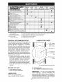
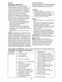
MAINTENANCE
SCHEDULE
BEFORE
EAC H
USE
Check for Loose Fasteners
,_ Clean / Inspect Grass Catcher *
_
AFTER
Check Tires
Check
Drive Wheels ***
Clean Lawn Mower****
_#,
EAC H
v'
v'
v'
v'
v'3
v'
v'
GENERAL
v_
vl
V_,2
_4
v'
_ Inspect Muffler
N Replace Spark Plug
I_' Replace Air Filter Paper Cartridge
Empty fuel system or add Stabilizer
*** Power-Propelled
mowers
**** Use a scraper
to clean under deck
BEFORE
STO RAG E
_V'
Check Engine Oil level
E Change Engine Oil
N Clean Air Filter
mowers
EVERY
100
HOURS
V'
ubrication
Clean and Recharge Battery **
* (if so equipped)
EVERY
25 HOURS
OR SEASON
v'
v'
O Check Drive Belt / Pulleys ***
W Check / Sharpen / Replace Blade
** Electric-Start
10
USE HOURS
M Clean under Drive Cover ***
_
EVERY
1
2
3
4
5
-
v'
=4
v'
Change more often if operating under a heavy load or in high outdoor
Service more often if operating in dirty or dusty conditions.
Replace blades more often when mowing in sandy soil.
Charge 48 hours at end of season.
And after each 5 hours of use.
LUBRICATION
RECOMMENDATIONS
The warranty on this lawn mower does not
cover items that have been subjected to
operator abuse or negligence. To receive
ful! value from the warranty, operator must
maintain unit as instructed in this manual.
Some adjustments wil! need to be made
periodically to properly maintain your unit.
At least once a season, check to see if
you should make any of the adjustments
described in the Service and Adjustments
section of this manual.
• At least once a year, replace the spark
plug, clean or replace air filter element
and check blade for wear. A new spark
plug and clean/new air filter element
assure proper air-fuel mixture and help
your engine run better and last longer.
• Follow the maintenance schedule in this
manual.
temperatures.
CHART
(_ Wheel
adjuster (on
each wheel)
(_ Engine oil
Mulcher
door hinge
pin
(_ Rear door
hinge
(_ Handle bracket mounting pins
BEFORE EACH USE
• Check engine oil level.
• Check for loose fasteners.
_
Spray
lubricant in Maintenance
See "ENGINE"
section.
IMPORTANT:
Do not oil or grease plastic
wheel bearings.
Viscous lubricants will
attract dust and dirt thatwill shorten the life of
the self-lubricating bearings. If you feel they
must be lubricated, use only a dry, powdered
graphite type lubricant sparingly.
LUBRICATION
Keep unit well lubricated
(See "LUBRICATION CHART").
12
LAWN MOWER
Always observe safety rules when performing any maintenance.
TIRES
• Keep tires free of gasoline, oil, or insect
control chemicals which can harm rubber.
• Avoid stumps, stones, deep ruts, sharp
objects and other hazards that may
cause tire damage.
DRIVE WHEELS
Check front drive wheels each time before
you mow to be sure they move freely.
The wheels not turning freely means trash,
grass cuttings, etc. are in the drive wheel area
and must be cleaned to free drive wheels.
If necessary to clean the drive wheels, be
sure to clean both front wheels.
1. Remove hubcaps, Iocknuts & washers.
2. Remove wheels from wheel adjusters.
3. Remove any trash or grass cuttings
from inside the dust cover, pinion and/
or drive wheel gear teeth.
4. Put wheels back in place.
NOTE: If after cleaning, the drive wheels
do not turn freely, contact a Sears or other
qualified service center.
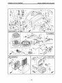
BLADE CARE
IMPORTANT: To ensure proper assembly,
center hole in blade must align with star
on blade adapter.
3. Be sure trailing edge of blade (opposite
sharp edge) is up toward the engine.
4. Install the blade bolt with the lock
washer and hardened washer into
blade adapter and crankshaft.
5. Use block of wood between blade and
lawn mower housing and tighten the
blade bolt, turning clockwise.
• The recommended tightening torque is
35-40 ft. Ibs.
IMPORTANT:
Blade bolt is heat treated.
If bolt needs replacing, replace only with
approved bolt shown in the Repair Parts
section of this manual.
For best results, mower blade must be kept
sharp. Replace a bent or damaged blade.
A CAUTION:
Use only a replacement
blade approved by the manufacturer of
your mower. Using a blade not approved
by the manufacturer of your mower is hazardous, could damage your mower and
void your warranty.
TO REMOVE BLADE
retainer
1. Disconnect spark plug wire from spark
plug and place wire where it cannot
come in contact with plug.
2. Turn lawn mower on its side. Make
sure air filter and carburetor are up.
3. Use a wood block between blade and
mower housing to prevent blade from
turning when removing blade bolt.
NOTE: Protect your hands with gloves
and/or wrap blade with heavy cloth.
4. Remove blade bolt by turning counterclockwise.
5. Remove blade and attaching hardware
(bolt, lock washer, hardened washer).
NOTE: Remove the blade adapter and
check the key inside hub of blade adapter.
The key must be in good condition to work
properly. Replace adapter if damaged.
TO REPLACE BLADE
1. Position the blade adapter on the engine crankshaft. Be sure key in adapter
and crankshaft keyway are aligned.
2. Position blade on the blade adapter.
13
Blade adapter
Key
Crankshaft
Lockwasher
(-
,,
Blade
Blade
bolt
Hardened
washer
,,,), ....
:',, ,,
\ ",,
Trailin/edge
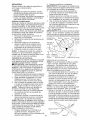
TO SHARPEN BLADE
NOTE: We do not recommend sharpening blade - but if you do, be sure the
blade is balanced. An unbalanced blade
will cause eventual damage to lawn
mower or engine.
• The blade can be sharpened with a file
or on a grinding wheel. Do not attempt
to sharpen while on the mower.
• To check blade balance, you will need
a 5/8" diameter steel bolt, pin, or a cone
balancer. (When using a cone balancer,
follow the instructions supplied with it.)
NOTE: Do not use a nail for balancing
blade. The lobes of the center hole may
appear to be centered, but are not.
• Slide blade on to an unthreaded portion
of the steel bolt or pin and hold the
bolt or pin parallel with the ground. If
blade is balanced, it should remain in a
horizontal position. If either end of the
blade moves downward, sharpen the
heavy end until the blade is balanced.
Center hole
5/8" bolt or pin
Blade
GRASS CATCHER
• The grass catcher may be hosed with
water, but must be dry when used.
• Check your grass catcher often for damage or deterioration.
Through normal
use it will wear. If catcher needs replacing, replace only with approved replacement catcher shown in the Repair Parts
section of this manual. Give the lawn
mower model number when ordering.
GEAR CASE
• To keep your drive system working
properly, the gear case and area around
the drive should be kept clean and free
of trash build-up. Clean under the drive
cover twice a season.
• The gear case is filled with lubricant to the
proper level at the factory. The only time
the lubricant needs attention is if service
has been performed on the gear case.
• If lubricant is required, use only Texaco
Starplex Premium 1 Grease, Part No.
750369. Do not substitute.
ENGINE
Maintenance, repair, or replacement of the
emission control devices and systems, which
are being done at the customers expense,
may be performed by any non-road engine
repair establishment or individual. Warranty
repairs must be performed by an authorized
engine manufacturer's service outlet.
LUBRiCATiON
Use only high quality detergent oi! rated
with API service classification
SG-SL.
Select the oil's SAE viscosity grade according
to your expected operating temperature.
SAE VISCOSITY GRADES
°F
-20
°c -_o
0
30
-2_
TEMPERATURE
-_o
RANGE
32
40
_
ANTICIPATED
BEFORE
80
_o
Oil fill cap /
dipstick
100
1o
4o
NEXT OIL CHANGE
NOTE: Multi-viscosity oils (5W30, 10W30
etc.) improve starting in cold weather, and
you should check your engine oil level frequently to avoid possible engine damage
from running low on oil.
Change the oi! after every 25 hours of operation or at least once a year if the lawn mower
is not used for 25 hours in one year.
Check the crankcase oil level before
starting the engine and after each five (5)
hours of continuous use. Tighten oil plug
securely each time you check the oil level.
TO CHANGE
Wipe off any spilled oil from lawn
mower or side of engine.
5. Fill engine with oil. Slowly pour oil
down the oil fill spout into the engine.
6. Wait one minute to allow oil to settle.
Use guage on oil fill cap/dipstick for
checking level. Insert dipstick into
the tube and rest the oil fill cap on the
tube. DO NOT thread the cap into the
tube when taking reading.
.
Upper _
60
_
1. Disconnect spark plug wire from spark
plug and place wire where it cannot
come in contact with plug.
2. Remove oil fill cap/dipstick; lay aside
on a clean surface.
3. Tip lawn mower on its side as shown
and drain oil into a suitable container.
Rock lawn mower back and forth to remove any oil trapped inside of engine.
ENGINE OIL
NOTE: Before tipping lawn mower to drain
oil, empty fuel tank by running engine until
fuel tank is empty.
14
mark
7. Continue adding small amounts of
oil and rechecking the dipstick until it
reads ful!. DO NOT overfill, or engine
will smoke on startup.
8. Always be sure to retighten oil fill cap/
dipstick before starting engine.
9. Reconnect spark plug wire to spark
plug.
AIR FILTER
Your engine will not run properly and may
be damaged by using a dirty air filter.
Replace the air filter every 100 hours of
operation or every season, whichever occurs first. Service air cleaner more often
under dusty conditions.
TO CLEANAIR FILTER
1. Remove cover.
2. Carefully remove cartridge.
3. Clean by gently tapping on a flat surface. If very dirty, replace cartridge.
ACAUTION: Petroleum solvents, such
as kerosene, are not to be used to clean
cartridge. They may cause deterioration
of the cartridge. Do not oil cartridge. Do
not use pressurizedair to clean or dry
cartridge.
4. Install cartridge,then replace cover.
Tab
Cartridge
Filter
MUFFLER
Inspect and replace corroded muffler as it
could create a fire hazard and/or damage.
SPARK PLUG
Replace spark plug at the beginning of
each mowing season or after every 100
hours of operation, whichever occurs
first. Spark plug type and gap setting
are shown in the "PRODUCT SPECIFICATIONS" section of this manual.
CLEANING
out. Water in engine can result in shortened engine life.
WATER WASHOUT FEATURE
Your lawn mower is equipped with a fitting
that allows quick and easy cleaning of
the underside of the housing. To use this
feature, proceed as follows:
1. Move lawn mower to an area of cut
grass or another hard surface.
NOTE: Water, grass and other debris will
drain from beneath the mower housing
during the washout process.
2. Remove grass catcher and discharge
chute assembly from lawn mower.
3. Close mulcher door (if equipped).
4. Connect a garden hose to the fitting
where shown.
IMPORTANT:
Be sure the garden hose is
not routed under the lawn mower housing
or entangled in the wheels.
5. Turn on water supply and check for
leaks at the fitting.
If no leaks are present, start engine (as
described in the Operation section of this
manual) and let engine run until the underside of the lawn mower is clean.
A WARNING:
Do not engage the drive
system during the washout process.
6. Shut off the engine.
7. Shut off water supply and remove hose
from fitting.
CAUTION: Do not remove hose from
fitting while engine is running. Water in
engine can result in shortened engine life.
8. Start engine (as described in the Operation section of this manual) and let
engine run for a full minute to remove
excess water from mower.
Hose
IMPORTANT:
For best performance,
keep mower housing free of built-grass
and trash. Clean the underside of your
mower after each use.
,ACAUTION:
Disconnect spark plug wire
from spark plug and place wire where it
cannot come in contact with plug.
• Clean the underside of your lawn mower
by scraping to remove build-up of grass
and trash.
• Clean engine often to keep trash from
accumulating.
A clogged engine runs
hotter and shortens engine life.
• Keep finished surfaces and wheels free
of all gasoline, oil, etc.
• We do not recommend using a garden
hose to clean lawn mower unless the
electrical system, muffler, air filter and
carburetor are covered to keep water
15
Fitting
CLEAN UNDER DRIVE COVER
Clean under drive cover at least twice a
season. Scrape underside of cover with
putty knife or similar tool to remove any
build-up of trash or grass on underside
of drive cover.
A
1.
2.
3.
WARNING: To avoid serious injury, before performing any service and adjustments:
Release control bar and stop engine.
Make sure the blade and all moving parts have completely stopped.
Disconnect spark plug wire from spark plug and place wire where it cannot come in
contact with plug.
LAWN MOWER
TO ADJUST CUTTING HEIGHT
See "TO ADJUST CUTTING HEIGHT" in
the Operation section of this manual.
NOTE: Always use factory approved
to assure proper fit and long life.
Blade adapter
REAR DEFLECTOR
The rear deflector, attached between the
rear wheels of your mower, is provided to
minimize the possibility that objects will
be thrown out of the rear of the mower
into the operator mowing position. If the
deflector becomes damaged, it should be
replaced.
Key
belt
Crankshaft
Lockwasher
Blade
Blade
bolt
Hardened
washer
TO
1.
2.
3.
REMOVE DRIVE BELT
Remove drive cover and belt keeper.
Remove belt from gearcase pulley.
Turn lawn mower on its side with air
filter and carburetor down.
4. Remove blade and blade adapter.
5. Remove belt from engine pulley.
TO ADJUST
_ '_
Trailin/edge
retainer
HANDLE
The handle on your lawn mower has three
(3) height positions - adjust to height that
suits you.
1. Remove knob and carriage bolt on one
side of the lower handle.
2. While holding handle assembly,
remove knob and carriage bolt from
opposite side, align hole in handle with
desired hole in handle bracket and
reassemble bolt and knob and tighten
securely.
3. Align opposite side of handle with
same positioning hole and secure with
bolt and knob.
Drive
cover
\
Gearcase
pulley
Handle
bracket
Belt
3er
J
TO REPLACE
Knob
Bolt
Belt
DRIVE
BELT
1. Place new drive belt on engine pulley,
inside tabs of belt retainer.
2. Route the other end of the new drive
belt through hole in housing.
3. Reinstall blade adapter and blade.
4. Return mower to upright position.
5. Install new belt on gearcase pulley.
6. Reinstall belt keeper and drive cover.
16
ENGINE
CARBURETOR
Maintenance, repair, or replacement of the
emission control devices and systems, which
are being done at the customers expense,
may be performed by any non-road engine
repair establishment or individual. Warranty
repairs must be performed by an authorized
engine manufacturer's service outlet.
ENGINE SPEED
Your carburetor is not adjustable. If your
engine does not operate properly due
to suspected carburetor problems, take
your lawn mower to a Sears or other
qualified service center for repair and/or
adjustment.
IMPORTANT:
Never tamper with the
engine governor, which is factory set for
proper engine speed. Overspeeding
the engine above the factory high speed
setting can be dangerous. If you think
the engine-governed high speed needs
adjusting, contact a Sears or other
qualified service center, which has proper
equipment and experience to make any
necessary adjustments.
Your engine speed has been factory set.
Do not attempt to increase engine speed
or it may result in personal injury. If you
believe that the engine is running too fast
or too slow, take your lawn mower to a
Sears or other qualified service center for
repair and adjustment.
Immediately prepare your lawn mower for storage at the end of the season or if the unit
will not be used for 30 days or more.
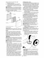
LAWN MOWER
IMPORTANT:
When folding the handle
for storage or transportation, be sure to
fold the handle as shown or you may damage the control cables.
When lawn mower is to be stored for a
period of time, clean it thoroughly, remove
all dirt, grease, leaves, etc. Store in a
clean, dry area.
1. Clean entire lawn mower (See
"CLEANING" in the Maintenance section of this manual).
2. Lubricate as shown in the Maintenance
section of this manual.
3. Be sure that all nuts, bolts, screws, and
pins are securely fastened. Inspect
moving parts for damage, breakage
and wear. Replace if necessary.
4. Touch up all rusted or chipped paint
surfaces; sand lightly before painting.
Operator
MOWING
POSITION
control bar
//
_b\
//!
FOLD
FORWARD
FOR
STORAGE
Upper
handle
Handle
knob
HANDLE
You can fold your lawn mower handle for
storage.
1. Loosen the two (2) handle knobs on
sides of the upper handle and allow
handle to fold down to the rear.
2. Remove the two (2) handle knobs and
carriage bolts on sides of the lower
handle and pivot entire handle assembly forward and allow it to rest on
mower.
3. Reinstall knobs and carriage bolts to
lower handle or handle brackets for
safe keeping.
• When setting up your handle from the
storage position, the lower handle will
require manually locking into the mowing position.
Lower handle
Handle
bracket
Knob
Bolt
17
ENGINE
ENGINE OIL
FUEL SYSTEM
Drain oil (with engine warm) and replace
with clean engine oil. (See "ENGINE" in
the Maintenance section of this manual).
CYLINDER
IMPORTANT:
It is important to prevent
gum deposits from forming in essential fuel
system parts such as carburetor,
fuel filter,
fuel hose, or tank during storage. Alcohol
blended fuels (called gasohol or using
ethanol or methanol)
can attract moisture
which leads to separation
and formation
of acids during storage. Acidic gas can
damage the fuel system of an engine while
in storage.
1. Remove spark plug.
2. Pour one ounce (29 ml) of oil through
spark plug hole into cylinder.
3. Pull starter handle slowly a few times
to distribute oil.
4. Replace with new spark plug.
OTHER
• Empty the fuel tank by starting the engine and letting it run until the fuel lines
and carburetor
are empty.
• Never use engine or carburetor
cleaner
products in the fuel tank or permanent
damage may occur.
• Use fresh fuel next season.
• Do not store gasoline from one season
to another.
• Replace your gasoline can if your can
starts to rust. Rust and/or dirt in your
gasoline will cause problems.
• If possible, store your unit indoors and
cover it to protect it from dust and dirt.
• Cover your unit with a suitable protective cover that does not retain moisture.
Do not use plastic. Plastic cannot
breathe, which allows condensation to
form and will cause your unit to rust.
IMPORTANT:
Never cover mower while
engine and exhaust areas are still warm.
ACAUTION:
Never store the lawn
NOTE:
Fuel stabilizer is an acceptable
alternative
in minimizing
the formation
of
fuel gum deposits during storage.
Add
stabilizer to gasoline in fuel tank or storage container.
Always follow the mix ratio
found on stabilizer container.
Run engine
at least 10 minutes after adding stabilizer
to allow the stabilizer to reach the carburetor.
Do not empty the gas tank and
carburetor
if using fuel stabilizer.
mower with gasoline in the tank inside a
building where fumes may reach an open
flame or spark. Allow the engine to cool
before storing in any enclosure.
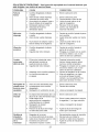
TROUBLESHOOTING
=See appropriate
to a Sears Parts & Repair Center.
PROBLEM
CAUSE
Does
not start
section
Dirty air filter.
2. Out of fue!.
3. Stale fuel.
.
in manual
unless
directed
CORRECTION
Clean/replace air filter.
2. Fill fuel tank.
3. Empty fuel tank and refill tank
with fresh, clean gasoline.
4. Empty fuel tank and refill tank
with fresh, clean gasoline.
5. Connect wire to plug.
.
4. Water in fuel.
5. Spark plug wire is
disconnected.
6. Bad spark plug.
7. Loose blade or broken
blade adapter.
8. Control bar in released
position.
9. Control bar defective.
10. Fuel valve lever (if so
equipped) in OFF position.
11. Weak battery (if equipped).
12. Disconnected battery
connector (if equipped).
13. Blown fuse (if equipped).
18
6. Replace spark plug.
7. Tighten blade bolt or
replace blade adapter.
8. Depress control bar to
handle.
9. Replace control bar.
10. Turn fuel valve lever
to the ON position.
11. Charge battery.
12. Connect battery to engine.
13. Replace fuse.
PROBLEM
Loss of power
CAUSE
.
.
3.
4.
5.
6.
Poor cut -
CORRECTION
Rear of lawn mower
housing or cutting blade
dragging in heavy grass.
Cutting too much grass.
Dirty air filter.
Buildup of grass, leaves,
and trash under mower.
Too much oil in engine.
Walking speed too fast.
1. Worn, bent or loose blade.
uReverl
2. Wheel heights uneven.
3. Buildup of grass, leaves
and trash under mower.
Excessive
vibration
.
Worn, bent or loose blade.
2. Bent engine crankshaft.
Starter rope
hard to pull
.
.
Engine flywheel brake is on
when control bar is released.
Bent engine crankshaft.
3. Blade adapter broken.
4. Blade dragging in grass.
1. Raise cutting height.
2. Raise cutting height.
3. Clean/replace air filter.
4. Clean underside of mower
housing.
5. Check oil level.
6. Cut at slower walking speed.
1. Replace blade. Tighten
blade bolt.
2. Set all wheels at same
height.
3. Clean underside of
mower housing.
1. Replace blade. Tighten
blade bolt.
2. Contact a Sears or other
qualified service center.
1. Depress control bar to
upper handle before
pulling starter rope.
2. Contact a Sears or other
qualified service center.
3. Replace blade adapter.
4. Move lawn mower to cut
grass or to hard surface.
Grass catcher
not filling
(if so equipped)
1. Cutting height too low.
2. Lift on blade worn off.
3. Catcher not venting air.
1. Raise cutting height.
2. Replace blade.
3. Clean grass catcher.
Hard to push
1. Grass is too high or wheel
height is too low.
2. Rear of lawn mower
housing or cutting blade
dragging in grass.
3. Grass catcher too ful!.
4. Handle height position not
right for you.
1. Raise cutting height.
2. Raise rear of lawn mower
housing one (1) setting
higher.
3. Empty grass catcher.
4. Adjust handle height to suit.
1.
2.
3.
4.
1.
2.
3.
4.
Loss of drive
or slowing of
drive speed
NEED
MORE
Belt wear.
Belt off of pulley.
Drive cable worn or broken.
"Loose" drive control system.
HELP?
You'll find the answer and more on managemyhome.com
•
•
•
•
Check/replace drive belt.
Check/reinstall drive belt.
Replace drive cable.
Adjust drive control.
- for free!
Find this and all your other product manuals online.
Get answers from our team of home experts.
Get a personalized maintenance plan for your home.
Find information and tools to help with home projects.
brought to you by Sears
19
Garantia ...................................................
Reglas de Seguridad ...............................
Especificaciones del Producto .................
Montaje / Pre-Operaci6n .........................
Operaci6n ................................................
Programa de Mantenimiento ...................
GARANTiA
Mantenimiento ..........................................
30-33
Servicio y Adjustes ...................................
33-34
Almacenamiento .......................................
35-36
Identificaci6n de problemas ...................... 36-37
Partes de repuesto ..................................
38-53
Servicio Sears .................................. Contratapa
.... 20
20-22
.... 22
.... 23
24-28
.... 30
TOTAL DE LA CORTADORA
DE ClaSPED CRAFTSMAN
POR 2 ANOS
Siesta
Segadora Craftsman Ilega a presentar algOn desperfecto por defectos de materiales
o fabricaci6n durante un plazo de dos a_os a partir de la fecha de compra, Ilevela de vuelta a
cualquiera de las tiendas Sears, al Centro de Repuestos y Reparaci6n, o a otro comercio donde se
vendan los equipos Craftsman, a efectos de que se la reparen sin costo (o bien se la reemplacen,
en caso que no sea posible repararla).
Siesta Segadora Ilega a ser utilizada con fines comerciales o arrendada,
vigencia por s61o 90 dias a partir de la fecha de compra.
La presente garantia
la presente garantia tendra
no cubre:
• Aquellas piezas fungibles que se desgastan por el uso normal, tales como las cuchillas rotatorias
de la cortadora, los adaptadores de las cuchillas, las correas, los filtros de aire y las bujias.
• Aquellas reparaciones que haya que hacer debido a mal uso o negligencia por parte del operador,
incluidos el arbol del cigOefial torcido u omisiones relativas al armado, manejo o mantenimieno de
la Segadora en un todo de acuerdo alas instrucciones provistas con el equipo.
La presente garantia se aplicara solamente
en tanto el articulo sea usado en los Estados Unidos.
Esta garantia le otorga a usted derechos legales especificos;
derechos, los cuales varian de estado a estado.
puede que usted tenga, ademas, otros
Sears, Roebuck and Co., Hoffman Estates, IL 60179
IMPORTANTE: Esta maquina cortadaora es capaz de amputar las manos y los manos y los pies y
de lanzar objetos. Si no se observan las instrucciones de seguridad siguientes se pueden producir
lesiones graves o la muerte.
_3k,Busque este simbolo
ciones de seguridad de
decir - i i iATENCION!!!
SU SEGURIDAD ESTA
que sefiala las precauimportancia. Quiere
i i iESTE ALERTO!!!
COMPROMETIDA.
_I, PRECAUCI6N:
El tubo de escape del motor,
algunos de sus constituyentes y algunos componentes del vehiculo contienen o desprenden
productos quimicos conocidos en el Estado de
California como causa de c_flncer y defectos al
nacimiento u otros dafios reproductivos.
_I_ADVERTENClA:
Siempre desconecte el
alambre de la bujia y pdngalo donde no pueda
entrar en contacto con la bujia, para evitar el
arranque por accidente, durante la preparacidn,
el transporte, el ajuste o cuando se hacen
reparaciones.
_:_PRECAUCI6N:
El silenciador y otras piezas
del motor Ilegan a sre extremadamente calien=
tes durante la operacidn y siguen siendo calf
entes despues de que el motor haya parado.
Para evitar quemaduras severas, permanezca
lejos de estas areas.
Ai_ADVERTENCIA:
Los bornes, terminales y
accesorios relativos de la bateria contienen
plomo o compuestos de plomo, productos
quimicos conocidos en el Estado de California
como causa de cancer y defectos al nacimiento
u otros dafios reproductivos. Lavar las manos
despues de manipularlos.
20
I. OPERACION
• Siempre use gafas de seguridad o anteojos
con protecci6n lateral cuando opere la segadora.
• Antes de empezar, debe familiarizarse
completamente con los controles y el uso
correcto de la maquina. Para esto, debe leer
y comprender todas las instrucciones que
aparecen en la maquina yen los manuales
de operaci6n.
• No ponga las manos o los pies cerca o
debajo de las partes rotatorias. Mantengase
siempre lejos de la abertura de la descarga.
• Permita que solamente las personas responsables que esten familiarizadas con las
instrucciones operen la maquina.
• Despeje el area de objetos tales como piedras, juguetes, alambres, huesos, palos, etc.
que pueden ser recogidos y lanzados por las
cuchillas.
• Aseg_rese que el area no se hallen personas, antes de segar. Pare la maquina si
alguien entra en el area.
• No opere la maquina sin zapatos o con
sandalias abiertas. P6ngase siempre zapatos
s61idos.
• No tire de la segadora hacia atras a menos
que sea absolutamente necesario. Mire
siempre hacia abajo y hacia detras antes y
mientras que se mueve hacia atras.
• Nunca dirigir el material descargado hacia
las personas. Evitar descargar material
contra paredes o barreras. El material puede
retornar al operador. Para la cuchilla cuando
se pasa por superficies de grava.
• No opere la segadora sin los respectivos
resguardos, las placas, el recogedor de
cesped u otros aditamentos dise ados para
su protecci6n y seguridad.
• Refierase alas instrucciones del fabricante
para el funcionamiento e instalaci6n de
accesorios. Use Qnicamente accesorios
aprobados pot el fabricante.
• Detenga la cuchilla o las cuchillas cuando
cruce pot calzadas, calles o caminos de
grava.
• Parar el motor cada vez que se abandona el
aparato, antes de limpiar la segadora o de
remover residuos del tubo.
• Apagar el motor y esperar hasta que las
cuchillas esten completamente paradas
antes de remover el receptor de hierba.
• Segar solamente con luz del dia o con una
buena luz artificial.
• No opere la maquina bajo la influencia del
alcohol o de las drogas.
Nunca opere la maquina cuando la hierba
este mojada. AsegQrese siempre de tener
buena tracci6n en sus pies; mantenga el
mango firmemente y camine; nunca corra.
Desconectar el mecanismo de propulsi6n
aut6noma o el embrague de transmisi6n en
las segadoras que Io tienen antes de poner
en marcha el motor.
Si el equipo empezara a vibrar de una
manera anormal, pare el motor y revise de
inmediato para averiguar la causa. Generalmente la vibraci6n suele indicar que existe
alguna averia.
II. OPERACION
SOBRE LAS CUESTAS
Los accidentes ocurren con mas frecuencia en
las cuestas. Estos accidentes ocurren debido a
resbaladas o caidas, las cuales pueden resultar
en graves lesiones. Operar la recortadora en
cuestas requiere mayor concentraci6n. Si se
siente inseguro en una cuesta, no la recorte.
HACER:
• Puede recortar a traves de la superficie de
la cuesta, nunca hacia arriba y hacia abajo.
Proceda con extrema precauci6n cuando
cambie de direcci6n en las cuestas.
• Renueva todos los objetos extrafios, tales
como guijarros, ramas, etc.
• Debe prestar atenci6n a hoyos, baches o
protuberancias. Recuerde que la hierba alta
puede esconder obstaculos.
NO HACER:
• No recorte cerca de pendientes, zanjas o
terraplenes. El operador puede perder la
tracci6n en los pies o el equilibrio.
• No recorte cuestas demasiado inclinadas.
• No recorte en hierba mojada. La reducci6n
en la tracci6n de la pisada puede causar
resbalones.
III. NINOS
Se pueden producir accidentes tragicos si el
operador no presta atenci6n a la presencia
de los nifios. A menudo, los nifios se sienten
atraidos por la maquina y por la actividad de
la siega. Nunca suponga que los nifios van a
permanecer en el mismo lugar donde los vio
por _ltima vez.
• Mantenga a los nifios alejados del area de
la siega y bajo el cuidado estricto de otra
persona adulta responsable.
• Este alerta y apague la maquina si hay nifios
que entran al area.
• Antes y cuando este retrocediendo, mire
hacia atras y hacia abajo para verificar si hay
nifios pequefios.
• Nunca permita que los nifios operen la maquina.
• Tenga un cuidado extra cuando se acerque
a esquinas donde no hay visibilidad, a los
arbustos, arboles u otros objetos que pueden
interferir con su linea de visidn.
IV. MANEJO
SEGURO
DE GASOLINA
Usar mucha atencidn cuando se maneja gasolina. La gasolina es extremamente inflamable y
los vapores son explosivos.
• Apagar todos los cigarrillos, cigarros, pipas y
otras fuentes de ignicidn.
• Usar solo un contenedor apropiado.
• Nunca quitar el tap6n de la gasolina o afiadir
carburante con el motor en marcha. Esperar
que el motor se enfrie antes de repostar la
gasolina.
21
• Nuncarepostarla maquinaal interiorde un
local.
• Nuncaguardarla maquinao el contenedor
degasolinadondehayunallamaabierta,
chispao luzpilotocomounacalderau otros
dispositivos.
• NuncaIlenarcontenedores
en unvehiculo,
en uncami6no caravanaconunforrode
plastico.Colocarsiempreloscontenedores
en elsuelolejosdesu vehiculoantesde
Ilenar.
• Quitarequiposquefuncionancongasolina
delcami6no caravanay repostarenel suelo.
Si estonoes posible,repostardichoequipo
conuncontenedorportatil,masbienquecon
unatoberadegasolina.
• Mantenerlatoberaencontactoconel bordo
deldepdsitodecarburanteo de laapertura
delcontenedor
siemprehastaterminarel
abastecimiento.
Nousarun dispositivode
cierre-apertura
dela tobera.
• Si el carburantecaeenla ropaquese Ileva,
cambiarselainmediatamente.
• NuncaIlenarenexcesoel depdsitode
carburante.Colocareltap6nde lagasolinay
apretardemodoseguro.
V. SERVIClO
• Nuncahagafuncionarunamaquinadentro
de unareacerrada.
• Nuncahagaajusteso reparaciones
mientras
el motorest¢enmarcha.Desconecte
el
cabledela bujia,y mantengaloa cierta
distanciadeCstaparaprevenirunarranque
accidental.
* Mantengalastuercasy lospernos,especialmentelospernosdelaccesoriode la
cuchilla,apretadosy mantengael equipoen
buenascondiciones.
* Nuncamanipuledeformaindebidalos
dispositivos
deseguridad.Controleregularmentesu funcionamiento
correcto.
* Mantengala maquinalibrede hierba,hojas
u otrasacumulaciones
dedesperdicio.
Limpielosderramesdeaceiteo combustible.
Permitaquela maquinaseenfrieantesde
almacenarla.
* Paree inspeccione
elequiposi le pegaa un
objeto.Reparelo,si es necesario,antesde
hacerloarrancar.
* En ning0ncasohayqueregularla alturade
lasruedasmientrasel motorestaen marcha.
* Loscomponentes
delreceptordela hierba
vansujetosa desgaste,da_osy deterioro,
quepuedenexponerlaspartesen movimientoo permitirqueobjetosseandisparados.Controlarfrecuentemente
y cuandosea
necesariosustituirconpartesaconsejadas
pot elfabricante.
* Lascuchillasdela segadoraestanafiladas
y puedencortar.Cubrirlashojaso Ilevar
guantes,y utilizarprecauciones
especiales
cuandoseefect0amantenimiento
sobrelas
mismas.
* Nocambieel ajustedelreguladordelmotor
ni excedasuvelocidad.
* Mantenero sustituirlasetiquetasde
seguridade instrucciones,
cuandosea
necesario.
,_ADVERTENClA:Estesegadoravieneequipadoconunmotorde combusti6n
internay nose
debeusarsobre,o cerca,de unterrenonodesarrollado
cubiertodebosques,dearbustoso de
cesped,o menosqueel sistemadeescapedelmotorvengaequipadoconunamortiguador
de
chispasquecumplaconlasleyeslocaleso estatales(si existen).Si se usaun amortiguador
de
chispas,el operadordebemantenerlo
encondicionesdetrabajoeficientes.
En elestadode California,la leyexigeIoanterior(Secci6n4442del"CaliforniaPublicResourcesCode").Otrosestadospuedencontarconotrasleyesparecidas.Lasleyesfederales
se aplicanen latierrasfederales.Su centrode Serviciomascercanotienedisponibleamortiguadoresdechispasparael silenciador(Veala secci6nde PARTESDEREPUESTO
en el
manualInglesdeldue_o).
NOmero de Serie:
Fecha de Compra:
Capacidad
y Tipo de Gasolina:
1.0 Cuartos (Regular sin PIomo)
Capacidad
de Aceite:
18.50nzas
Tipo de Aceite
Buj[a
(API SG-SL):
(Abertura:
Tolerancia
Torsi6n
.030")
de Valvula
del Perno
SAE 30 (Debajo
NGK
(+ 0.004 mm)
de la Cuchilla:
o SAE
10W30
BPR6ES
Admisi6n:
35-40
0°C/32°F)
0.015
mm; Descarga:
0.020
mm
ft. Ibs.
• El nOmero del nodelo y el de serie se encuentran en la calcomania adjunta a la parte trasera
de la caja de la segadora. Debe registrar tanto el nOmero de serie come la fecha de compra y
mantengalos en un lugar seguro para refencia en el futuro.
22
Acuerdos
de Protecci6n
Congratulaciones por su buena compra. Su
nuevo producto Craftsman® esta diseSado
y fabricado para funcionar de modo liable pot
muchos a_os. Pero como todos los productos,
puede necesitar alguna reparaci6n de tanto
en tanto. En este caso tenet un Acuerdo de
Proteccidn para la Reparacidn puede hacerles
ahorrar dinero y fastidios.
para la Reparaci6n
• Ayuda rapida por telefono - soporte tele=
f6nico por parte de un representante Sears
sobre productos que requieren un arreglo en
casa, y ademas una programaci6n sobre los
a reglos mas convenientes.
Cuando se ha comprado el Acuerdo, basta con
una Ilamada telef6nica para programar el servicio. Puede Ilamar cuando quiera, dia y noche o
fijar en linea una cita para obtener el servicio.
Sears tiene mas de 12.000 especialistas
profesionales en la reparaci6n, que tienen
acceso a mas de 4.5 millones de partes y
accesorios de calidad. Este es el tipo de
profesionalidad con que puede contar para
ayudar a alargar la vida del producto que acaba
de comprar, pot muchos aSos. iCompre hoy su
Acuerdo de Protecci6n para la Reparaci6n!
Se aplican algunas limitaciones
y e×clusiones. Para conocer los precios y tenet
mas information, Ilame al 1=800=827=6655.
Servicio de Instalaci6n Sears
Para la instalacidn profesiona/ Sears de
aparatos de casa, puertas de garaje,
calentadores de agua y otros importantes
articulos para la casa, en U.S.A. Ilamar a
1 =800=4=MY=HOME®.
Compre ahora un Acuerdo de Proteccidn para
la Reparacidn y protegese de molestias y gastos inesperados.
Un Acuerdo incluye los puntos siguientes:
• Servicio experto de nuestros 12.000 especialistas profesionales en la reparaci6n.
• Servicio ilimitado sin cargo alguno para
las partes y la mano de obra sobre todas las
reparaciones garantizadas.
• Sustituci6n
de! producto si su producto
garantizado no puede set arreglado.
• Descuento del 10% sobre el precio cot=
riente del servicio y de las partes relativas al
servicio no cubiertas pot el acuerdo; tambien
el 10% menos sobre el precio corriente de
un control de mantenimiento preventivo.
Estos accesorios estaban disponibles cuando se produjo la segadora. No son facilitados
junto al
cortacesped.
Tambien estan disponibles en la mayoda de las tiendas de Sears y en los centros
de servicio. Algunos de estos accesorios tal vez no se apliquen a su segadora.
RENDIMIENTO
DE LA SEGADORA
DESVIADOR
DE RECORTES
PARA SEGADORAS
ESTABILIZADORES
CON DESCARGA
TRASERA
RECOREDOR
PARA
SEGADORAS
CON DESCARGA
LATERAL
RECOREDOR
PARA
SEGADORAS
CON DESCARGA
TRASERA
MANTENIMIENTO
DE LA SEGADORA
SILENCIADORES
FILTROS DE AIRE
ADAPTADORES
CORREAS
CUCHILLAS
DE CUCHILLA
23
BUJiAS
ACEITE
RUEDAS
DEL
MOTOR
Lea estas instrucciones y este manual completamente antes de tratar de montar u operar su segadora nueva.
IMPORTANTE: Este cortacesped viene SIN ACEITE O GASOLINA en el motor.
Su segadora nueva ha sido montada en la fabrica con la excepci6n de aquellas partes que se dejaron sin montar por razones de envio. Todas las partes como las tuercas, las arandelas, los pernos,
etc., que son necesarias para completar el montaje han sido colocadas en la bolsa de partes. Para
asegurarse que su segadora funcione en forma segura y adecuada, todas las partes y los articulos
de ferreteda que se monten tienen que set apretados seguramente. Use las herramientas correctas,
como sea necesario, para asegurar que se aprieten adecuadamente.
PARA REMOVER
LA SEGADORA
LA CAJA DE CARTON
1.
2.
3.
4.
DE
Soporte
de mango
Remueva las partes sueltas que se incluyen
con la segadora.
Cortelasdosesquinasdelosextremosdelacaja
de cart6n y tienda el panel del extremo piano.
Remueva todo el material de empaque, excepto la curia entre el mango superior y 61
inferior, y la curia que sujeta la barra de los
control que exige la presencia del operador
junto con el mango superior.
Haga rodar la segadora hacia afuera de la
caja de cart6n y revisela cuidadosamente
para verificar si todavia quedan partes
sueltas adicionales.
COMO PREPARAR
Perno
.......... ----
SU SEGADORA
PARA MONTAR EL RECOGEDOR
CESPED
PARA DESDOBLAR EL MANGO
IMPORTANTE:
Despliegue el mango con
mucho cuidado para no pellizcar o dafiar los
cables de control.
1. Levante los mangos hasta que la secci6n
del mango inferior se asegure en su lugar,
en la posici6n para segar.
2. Remueva la curia protectora, levante la secci6n
del mango superior hasta su lugar en el mango
inferior, y apriete ambas manillas del mango.
3. Remueva la curia del mango que sujeta la
barra de los control que exige la presencia
del operador junto con el mango superior.
El mango de la segadora puede ajustarse
seg0n le acomode para segar. Refierase a
"AJUSTE DEL MANGO" en la secci6n de
Servicio y Ajustes de este manual.
Barra de
que exige la
presencia det
operador
DE
1.
Ponga el bastidor del recogedor de cesped
en la bolsa del cesped con la parte rigida
de la bolsa en la parte inferior. Aseg0rese
que el mango del bastidor este en el exterior de la parte superior de la bolsa.
2. Deslice los sujetadores de vinilo sobre el
bastidor.
AVISO: Si los sujetadores de vinilo estan muy
duros, metalos en agua caliente por algunos
minutos. Si se moja la bolsa, dejela que se
seque antes de usarla.
POSICION
PARA
_
_i "'SEGAR
j_/ //
.v /
///
LEVANTAR
Mango
superior
Sujetadore.,
de vinito
Manitla det
mango
Mango Inferior
24
Abertura
det bastidor
PARA INSTALAR LOS ACCESORIOS
Su segadora fue enviada lista para usarse
como una acolchadora de capa vegetal. Para
convertirla de modo que pueda ensacar o
descargar, refierase a "PARA CONVERTIR
LA SEGADORA" en la secci6n de Operaci6n
de este manual.
FAMILIARICESE
CON SU SEGADORA
LEA ESTE MANUAL DEL DUENO Y LAS REGLAS DE SEGURIDAD ANTES DE OPARAR SU
SEGADORA.
Compare las ilustraciones con su segadora para familiarizarse con la ubicaci6n de
los diversos controles y ajustes. Guarde este manual para referencia en el futuro.
Estos simbolos pueden apareser
producto. Aprenda y comprenda
ATTENCION
O
ADVERTENCIA
MOTOR
ENCENDIDO
MOTOR
APAGADO
sobre su segadora
sus significados.
R,_PIDO
LENTO
o en la literatura
ESTRANGU
LACION
COMBUSTIBLE
proporcionada
ACEITE
con el
PELIGRO, GUARDE LAS
MANOS Y LOS PIES LEJOS
Barra de control que exige la
presencia del operador
Palancas de control de la impulsi6n
Manilla del mango
Tapa del deposito de la gasolina
Cord6n
arrancador
Valvula del combustible
Bujia
Recogedor
de cesped
Filtro de aire
Ajustador de
la rueda (en
cada rueda)
Tapa del deF
de aciete del mo=
tor con varilla indicadora de nivel
Silenciador
Cubierta de
la impulsi6n
Puerta de la acolchadora
Caja
IMPORTANTE: Este cortacesped viene
SIN ACEITE O GASOLINA en motor.
CUMPLE CON
Las segadoras
los estandares
Product Safety
LOS REQUISITOS DE SEGURIDAD DE LA CPSC
a motor, que se conducen desde la parte de atras, rotatorias, Sears, cumplen con
de seguridad del American National Standards Institute y de la U.S. Consumer
Commission. Ai_PRECAUCl6N:
La cuchilla gira cuando el motor esta funcionando.
Barra de control que exige la presencia del
operador - tiene que sujetarse abajo, junto
con el mango, para hacer arrancar el motor,
Sueltela para parar el motor.
Puerta de la acolchadora
- permite la conver=
si6n para la operaci6n de descarga o ensacado. 25
Palancas de control de la impulsion - se usa
para enganchar la segadora para movimiento
hacia adelante impulsada a motor.
Cord6n arrancador - se usa para hacer arrancar el motor.
La operaci6ndecualquier
SEGURIDAD
segadorapuedehacerque
saltenobjetosextra_osdentrode
susojos,Ioquepuedeproducir
da_osgravesenestos.Siempre
useanteojosdeseguridado protecci6npara
losojosmientrasoperesu segadorao cuando
hagaajusteso reparaciones.
Recomendamos
gafaso unamascaradeseguridaddevisi6n
ampliadeseguridadusadasobrelasgafas.
COMO USAR SU SEGADORA
VELOCIDAD DEL MOTOR
La velocidad del motor se estableci6 en la fa=
brica para un rendimiento 6ptimo. La velocidad
no se puede ajustar.
CONTROL DE ZONA DEL MOTOR
,_ PRECAUCI6N:
Las regulaciones federales
exigen que se instale un control para el motor
en esta segadora para reducir a un minimo el
riesgo de lesionarse debido al contacto con la
cuchilla. Pot ningQn motivo trate de eliminar
la funci6n del control del operador. La cuchilla
gira cuando el motor esta funcionando.
• Su segadora viene equipada con una barra
de controles que exigen la presencia del
operador, Io que requiere que el operador
este detras del mango de la segadora para
hacerla arrancar y operarla.
Torniquete
ajuste
PARA AJUSTAR LA ALTURA DE CORTE
Levante las ruedas para el corte bajo y baje
las ruedas para el corte alto, ajuste la altura de
corte para que se acomode a sus requisitos. La
posici6n del medio es la mejor para la mayoria
de los cespedes.
• Para cambiar la altura de corte, levante
encendido la palanca del ajustador hacia la
rueda, mueva la rueda hacia arriba o hacia
abajo de modo que se acomode a sus requisitos y lanzamiento la palanca. AsegOrese
que todas las ruedas queden igualmente
ajustadas.
AVlSO: El ajustador esta correctamente colocado cuando la palanca estan insertadas en el
agujero del placa.
CONTROL DE LA IMPULSION
, La autopropulsi6n se controla manteniendo
la palanca de mando operador presente
abajo hacia el mango y tirando cualquiera
palanca de accionamiento atras hacia el
mango. Cuanto mas lejos se tira a palanca
hacia el mango, mas rapida ira la unidad.
• El movimiento hacia adelante se detiene cuando sea la palanca de mando operador presente o a palanca de accionamiento se sueltan.
Para detener el movimiento hacia adelante sin
apagar el motor, soltar s61o a palanca de accionamiento. Mantener la palanca de mando
operador presente abajo contra el mango para
continuar a cortar sin autopropulsi6n.
AVlSO: Si despues haber desenganchado
de la palanca de control, la segadora no roda
hacia atras, empuje la segadora un poco hacia
adelante para desenganchar las ruedas de la
impulsi6n.
• Para mantener el mando conectado cuando
se da la vuelta a una esquina, empujar el
mango para levantar las ruedas delanteras
del terreno mientras se gira la cortadora.
Barra de control que
PARA
ENGANCHAR EL
CONTROL DE LA
IMPULSION
PALANCA HACIA ATRAS PARA ,A/
BAJAR EL CORTAC¢:SPED
Palanca de
PALANCA HACIA ajustes
ADELANTE PARA
LEVANTAR EL
CORTAC¢:SPED
Placa
det operador
Palancas
de la
impulsi6n
CONTROL DE LA
IMPULSION
DESENGANCHADO
AJUSTE DEL MANDO
Ocasionalmente, el sistema de mando puede
"aflojarse", provocando una disminuci6n de la
velocidad. Hay un torniquete en la sede del
mando para apretar la tensi6n del cable. Proceder de la siguiente manera:
1. Apagar la unidad y desconectar el cable de
bujia de la bujia.
2. Vuelta el torniquete para aumentar la velocidad del mecanismo.
3. Opere la segadora para probar la velocidad del mecanismo. Reajuste segQn Io
requerido.
4. Si las condiciones no mejoran despues
de los pasos descritos (la velocidad hacia
adelante queda la misma), la correa de
transmisi6n esta desgastada y tiene que ser
sustituida.
26
t
PARA CONVERTIR LA SEGADORA
Su segadora fue enviada lista para usarse como
acolchadora de capa vegetal. Para convertirla a
una operaci6n de ensacado o de descarga:
SEGADORAS CON DESCARGA TRASERA
I
• Levantar la puerta trasera de cortacesped
y colocar los ganchos del armaz6n de la
recolectora de hierba en los soporte del
recogedor de cesped.
• Para pasar a la operaci6n de acolchamiento,
remover la recolectora de hierba y cerrar la
puerta trasera.
\
\
Abierto la
[
contra ta
descarga
trasera
Soporte det quincio
Mango det
bastidor det
-.._.recogedorde
-\
c',sped
I
I
Desviador
de ta descarga
Gancho lateral del
bastidor det recogedor
\
AVISO: Le puerta trasara seguira siendo abierto hasta la barra de control que exige la presencia del operador se mantiene a la mango.
,_i PRECAUClON:
No fuerce la puerta trasera
para cerrarse. El dafio grave a su segadora
podia resultar.
PASOS SIMPLES DE RECORDAR
CUANDO CONVIERTA SU SEGADORA
PARA ACOLCHAMIENTO
1.
2.
La puerta trasera cerrada.
La protecci6n contra la descarga cerrada y
trabado.
PARA ENSACAMIENTO TRASERO -
1.
2.
SEGADORAS
CON DESCARGA
Recogedor del cesped instalado.
La protecci6n contra la descarga cerrada y
trabado.
PARA DESCARGA LATERAL-
LATERAL
1. La puerta trasera cerrada.
2. La desviador de la descarga instalada.
,A PRECAUCION:
No haga funcionar su
segadora sin la placa de la acolchadora sin
el recogedor cesped aprobados en su lugar.
Nunca trate de operar la segadora cuando se
halla removido la puerta trasera o cuando se
ha removido a puerta trasera o cuando esta un
poco abierta.
• La puerta trasera tiene que estar cerrada.
• Abra la protecci6n contra la descarga y
instale el desviador de contra la descarga
debajo de la protecci6n como se muestra.
• La segadora esta lista para la operaci6n de
la descarga.
• Para convertir a la operaci6n de ensacado
o de descarga, el desviador de la descarga
debe set removido y la protecci6n contra la
descarga debe estar cerrada y trabado.
27
AGREGUE GASOLINA
• Llene el estanque de combustible hasta la
parte inferior del cuello de relleno del estanque de gasolina. No Io Ilene demasiado.
Use gasolina regular, sin plomo, nueva y limpia con el minimo de 87 octanos. No mezcle
el aceite con la gasolina. Para asegurar
que la gasolina utilizada sea fresca compre
estanques los cuales puedan ser utilizados
,_iLdurante los primeros 30 dias.
PRECAUClON: Limpie el aceite o el
combustible derramado. No almacene, derrame
o use gasolina cerca de una llama expuesta.
AI_PRECAUCI(DN: Los combustibles
PARA VACIAR
EL RECOGEDOR
DE
CESPED
1. Levante el recogedor de cesped usando el
mango del bastidor.
2. Remueva el recogedor de cesped, con los
recortes, de debajo del mango de la segadora.
3. Vacie los recortes de la bolsa.
AVlSO: No arrastre la bolsa cuando la vacie;
se producira un desgaste innecesario.
Mango det
bastidor
del
edor
de cesped
mezclados con alcohol (conocidos como
gasohol, o el uso de etanol o metanol) pueden
atraer la humedad, la que conduce a la
separaci6n y formacidn de acidos durante el
almacenamiento. La gasolina acidica puede
dafiar el sistema del combustible de un motor
durante el almacenamiento. Para evitar los
problemas con el motor, se debe vaciar el
sistema del combustible antes de guardarlo
por un periodo de 30 dias o mas. Vacie el
estanque del combustible, haga ar rancar el
motor y hagalo funcionar hasta que las lineas
del combustible y el carburador queden vacios.
La pr6xima temporada use combustible nuevo.
Vea las Instrucciones Para El Almacenamiento
para mas informaci6n. Nunca use productos de
limpieza para el motor o para el carburador en
el estanque del combustible pues se pueden
producir dafios permanentes.
Mango de cesped
ANTES DE HACER ARRANCAR
MOTOR
EL
AGREGUE ACEITE
Su segadora fue enviada sin aceite en el motor.
Para el tipo y el grado del aceite a utilizar, vea
el "MOTOR" en la secci6n del Mantenimiento
de este manual.
,_PRECAUCl6N:
NO sobrellene el motor con
aceite, o fumara pesa demante del silenciador
cuando Io valla a arrancar.
1. AsegQrese que la segadora este nivelada.
2. Remueva la vafila medidora de aceite del tubo
de desarga de aceite.
3. Usted recibe un envase de aceite con la
unidad. Vierta lentamente el envase entero
de aceite en el tubo de relleno del motor.
4. Inserte y apriete la varilla medidora de aceite.
IMPORTANTE:
• Revise el nivel del aceite antes de cada uso.
Agregue aceite si es necesario. Llene hasta la
linea de Ileno en la varilla medidora de nivel.
• Cambie el aceite despues de 25 horas de
operaci6n o una vez pot temporada. Puede
necesitar cambiar el aceite mas a menudo
cuando las condiciones son polvorosas o sucias. Vea "PARA CAMBIAR EL ACEITE DEL
MOTOR" en la seccion de Mantenimiento de
este manual.
Tapa det deposito
_
de aceite _%0o_
con
/"
/_--_o
varitta ]\.
__
-""'0%_
.Z._
-d-_"_
de
nivel _"_
PARA HACER ARRANCAR
Marca
EL MOTOR
AVISO: Debido a las capas protectoras del motor, una cantidad pequefia de humo puede estar presente durante el uso inicial del producto
y se debe considerar normal.
1. Asegurase que valvula del combustible este
en la posici6n ON.
2. Mueva la palanca de la estrangulaci6n a la
Tapa del
rettenador
de gasolina
__
su e,,o,
Marca
PARA PARAR EL MOTOR
,, Para parar el motor y si no intenta ponerlo en
marcha de nuevo, alivie la barra de control
que exige la presencia del operador. Espere
hasta que la cuchilla y todas las piezas m6=
viles se hallan parado y mueva la valvula del
combustible a la posicion APAGADO (OFF).
_'
28
pos c deON
6n <I",1)
3.
Sujete la barra de controles que exigen la
presencia del operador abajo en el mango
y tire el mango del arrancador rapidamente.
No permita que el cord6n arrancador se
devuelva abruptamente.
AVlSO: La palanca de la estrangulaci6n
comienza a moverse automaticamente a la
posici6n de APAGADO (OFF) cuando la barra
del control de la presencia del operador se
mantiene hacia el mango.
APAGADO
(OFF)
Patanca de ta
ulacidn
CONSEJOS
CHAR
PARA
SEGAR
Y ACOL-
IMPORTANTE: Para obtener el mejor
rendimiento mantenga la caja de la segadora
sin acumulacion de cesped y basura. Vea
"LIMPIEZA" en la seccion de Mantenimento de
este manual.
• La cuchilla acolchadora especial va a volver
a cortar los recortes de cesped muchas
veces, y los reduce en tamafio, de modo que
si se caen en el cesped se van a dispesar
entre este y no se van a notar. Tambien, el
cesped acolchado se va a deshacer rapidamente entregando substancias nutritivas para
el cesped. Siempre acolche con la velocidad
del motor (cuchilla) mas alta, pues asi se
obtendra la mejor acci6n de recorte de las
cuchillas.
• Evite cortar el cesped cuando este mojado.
El cesped mojado tiende a format montones
e interfiere con la acci6n de acolchado.
La mejor hora para segar el cesped es
temprano en la tarde. A esa hora este se ha
secado y el area recien cortada no quedara
expuesta al sol directo.
• Para obtener los mejores resultados, ajuste
la altura del corte de la segadora de modo
que esta corte solamente el tercio superior
de las hojas de cesped. En el caso de que el
cesped haya crecido demasiado, puede set
necesario el elevar la altura del corte para
reducir el esfuerzo necesario para empujar la
segadora y para evitar sobrecargar el motor,
dejando montones de recortes de cesped.
Para un cesped muy pesado, reduzca el ancho del corte pasando pot encima del lugar
anteriormente cortado y siegue lentamente.
Valvula det combustible
ONSEJOS
PARA SEGAR
PRECAUClON: No utilizar dispositivos antipaja de la hoja en la segadora ya que estos
accesorios son peligrosos, pueden dafiar su
segadora y anular su garantia.
• Bajo ciertas condiciones, tal como cesped
muy alto, puede ser necesario el elevar la
altura del corte para reducir el esfuerzo
necesario para empujar la segadora y para
evitar sobrecargar el motor, dejando montones de recortes de cesped. Puede que sea
necesario reducir la velocidad del recorrido
y/o haga funcionar la segadora sobre el area
por segunda vez.
• Para un corte muy pesado, reduzca el ancho
del corte pasando parcialmente por encima
del lugar anteriormente cortado y siegue
lentamente.
• Para un mejor ensacado del cesped y para la
mayoria de las condiciones de corte, la velocidad del motor debe ajustarse a la posici6n
de R/_PIDO.
• Los poros en los recogedores de cesped de
tela pueden Ilenarse con mugre y polvo con
el uso y los recogedores recaudaran menos
cesped. Para evitar este, rocie el recogedor
con la manguera de agua regularmente y
dejelo secarse antes de usarlo.
• Mantenga la parte superior del motor, alrededor del arrancador, despejada y sin recortes
de cesped y paja. Esto ayudara el flujo del
aire del motor y extendera su duraci6n.
MAX 1/3
• Ciertos tipos de cesped y sus condiciones
pueden exigir que un area tenga que ser
acolchada pot segunda vez para esconder
completamente los recortes. Cuando se haga
el segundo corte, siegue atravesado (en
forma perpendicular) a la pasada del primer
corte.
• Cambie su patr6n de corte de semana a
semana. Siegue de norte a sur una semana
y luego cambie de este a oeste la pr6xima
semana. Esto evitara que el cesped se
enrede y cambie de direcci6n.
29
PROGRAMA
DE
ANTES
MANTENIMIENTO
S
Revisar
si hay Sujetadores
Sueltos de Cesped *
Limpiar/Inspeccionar
el Recogedor
_1_
E
Controlar
los NeumAticos
I_
Controlar las Ruedas Motrices ***
Limpiar la Segadora ....
if
_
Limpiar debajo la Cubierta
Revisar las Correas
de la Transmisi6n
***
y las Poleas Impulsadas
***
Revisar
/ Afilar / Cambiar
Lubricacion
Limpiar / Recargar
DESPUES
CADA
CADA
CADA
ANTES DEL
DEUSO
CADA DEUSO
CADA HORAS
10
25 HORAS O HORAS
100
TEMPORADA
ALMACENAMIENTO
I_
_1_
!_
i/
I_
_1_3
i/
la Cuchilla
la Bateria **
if
I_
Revisar el nivel del Aceite
M
Cambiar
el Aceite
del motor
1_,2
Limpiar el Filtro
de Aire
Inspeccionar
el Silenciador
O
Cambiar
Cambiar
la Cartucho
Bujia
el
_
t_
t_
de Papel del Filtro de Aire
Vaciar el sistema del carburante
o afiadir un estabilizador de carburante.
, (si viene equipado)
1 ** Segadoras con Arranque Electrico 2 *** Segadoras con Poder Propulsor
3 **** Utilizar una rasqueta para limpiar 4 debajo de la cubierta del cortacesped
5-
iv'
Cambiar mgts a menudo cuando se opere bajo carga pesada o en ambientes con altas temperaturas.
Dar servicio mAs a menudo cuando se opere en condiciones sucias o polvorosas.
Cambie las cuchillas m__sa menudo cuando siegue en terreno arenoso.
Cargar por 48 horas al fin de la temporada.
Y despu_s de 5 horas de funcionamiento.
TABLA
RECOMENDACIONES
GENERALES
La garant{a de esta segadora no cubre los
articulos que han estado sujetos al abuso o a
la negligencia del operador. Para recibir todo
el valor de la garantia, el operador tiene que
mantener la segadora segQn las instrucciones
descritas en este manual.
Hay algunos ajustes que se tienen que hacer
en forma peri6dica para poder mantener su
unidad adecuadamente.
AI menos una vez cada estaci6n comprobar
si es necesario efectuar los ajustes descritos
en las secciones de Servicio y Ajustes de este
manual.
• Una vez al a_o, cambie la bujia, limpie o
cambie el elemento del filtro de aire y revise
si la cuchilla esta desgastada. Una bujia
nueva y un elemento del filtro de aire limpio/
nuevo aseguran la mezcla de aire=combustible adecuada y ayudan a que su motor
funcione mejor y que dure mas.
• Siga el programa de mantenimiento en este
manual.
DE LUBRICACION
(_ Ajustador
de la rueda
(_ Aceite del
motor
(_ Bisagra
la puerta
de la acolchadora
(_ Bisagra
de la
puerta
traser
(_ Clavija de montaje del puntal del mango
ANTES DE CADA USO
• Revise el nivel del aceite del motor.
• Revise si hay sujetadores sueltos.
(_ Rocie el lubricante
(_) Vea "MOTOR"
en la seccion
de Mantenimiento
IMPORTANTE: No aceite o engrase los rodamientos de la rueda de plastico. Los lubricantes
viscosos atearan polvo y mugre, Io acortara la
duracion de los rodamientos autolubricantes. Si
cree que tienen que lubricarse, use Iosamente
un lubricante tipo crafito, de polvo seco, en
forma moderada.
LUBRICACION
Mantenga la unidad bien lubricada
(vea la "TABLA DE LUBRICAClON").
30
SEGADORA
Siempre observe las reglas de seguridad cuando haga el mantenimiento.
LLANTAS
• Mantenga las Ilantas sin gasolina, aceite o
substancias quimicas para control de Jnsectos que pueden dafiar la goma.
• Evite los tocones, las piedras, las grietas profundas, los objetos afilados y otros peligros
que pueden dafiar a las Ilantas.
RUEDAS DE IMPULSI6N
Revise las ruedas de impulsi6n delanteras cada
vez antes de segar, para asegurarse de que se
mueven libremente. Si las ruedas no giran libremente quiere decir que hay basura, recortes
de cesped, etc. en el area de las ruedas de
impulsi6n y tienen que limpiarse para liberarlas.
Es necesario limpiar las ruedas de impulsi6n;
revise ambas ruedas delanteras.
1. Remueva los tapacubos, las tuercas de
seguridad y las arandelas.
2. Remueva las ruedas de los ajustadores de
las ruedas.
3. Remueva la basura y los recortes de
cesped de dentro de la cubierta contra
el polvo, pifi6n y/o de los dientes de los
engranajes de las ruedas de impulsi6n.
4. Ponga las ruedas de vuelta en su lugar.
AVlSO: Si despues de limpiar las ruedas de
impulsi6n no giran libremente, p6ngase en
contacto con su centro de servicio Sears o con
un otro centro de servicio cualificado.
2. Ponga la cuchilla en el adaptador.
IMPORTANTE: Para asegurar la instalacion apropiada, posicione el agujero central de la cuchilla
con la estrella del conjunto del adaptador.
3. AsegQrese de que el borde de salida de
la cuchilla (opuesto al borde afiiado) este
hacia arriba hacia el motor.
4. Instale el perno de la cuchilla con la arandela de seguridad y la arandela endurecida
en el adaptador de la cuchilla y el ciguefial.
5. Use un bloque de madera entre la cuchilla
y la caja de la segadora y apriete el perno
de la cuchilla girandolo en el sentido en que
giran las manillas del reloj.
• La torsi6n para apretar recomendada es de
35 - 40 pies libras.
IMPORTANTE: El perno de la cuchilla es tratado
a calo. Si es necesario sustituir los pernos,
sustituirlos s61o con pernos aprobados mostrados
en la secci6n Partesde Reparaci6n de este manual.
Adaptador de
la cuchitta
Ranura
Chavetero del
" uenal
Arandela de
seguridad
mo Arandela
de la
endurecida
cuchitta
Borde
e correa
CUIDADO DE LA CUCHILLA
Para obtener los mejores resultados, la cuchilla
PARA AFILAR LA CUCHILLA
de la segadora tienen que mantenerse afilada.
AVlSO: No recomendamos el afilar la cuchilla
,_mbie la cuchilla doblada o dafiada.
- pero si Io hace, asegQrese de que quede
PRECAUClON:
Usar solamente la cuchilla
balanceada. Se tiene que tener cuidado de
de repuesto aprobada por el fabricante de su
mantenerla balanceada. Una cuchilla que no
segadora. Usar una cuchilla no aprobada por
esta
balanceada va a producir eventualmente
el fabricante de su segadora es peligroso, pudafio en la segadora o en el motor.
erie dafiar su segadora y anular su garantia.
• La cuchilla puede afilarse con una lima o en
PARA REMOVER LA CUCHILLA
una rueda rectificadora. No trate de afilarla
1. Desconecte el alambre de la bujia y p6ngalo en
mientras se encuentra en la segadora.
donde no pueda entrar en contacto con esta.
• Para revisar el balance de la cuchilla, va a
2. Haga descansar la segadora en su lado.
necesitar un perno de acero de 5/8", una
AsegQrese que el filtro de aire y que el
clavija o un balanceador c6nico. (Cuando se
carburador queden mirando hacia arriba.
use un balanceador c6nico, siga las instruc3. Use un bloque de madera entre la cuchilla
ciones que vienen con el balanceador.)
y la caja de la segadora para evitar que la
AVlSO:
No use un elavo para balancear la
cuchilla gire cuando se le quite el perno.
cuchilla.
Los 16bulos del agujero central pueden
AVlSO: Proteja sus manos con guantes y/o
aparecer como centrados, pero no Io estan.
envuelva la cuchilla con una tela gruesa.
• Deslice la cuchilla en una parte no roscada
4. Remueva el perno de la cuchilla girandolo
del perno de acero o clavija y sujete el perno
en el sentido contrario en que giran las
o la clavija paralelo al suelo. Si la cuchilla esta
manillas del reloj.
balanceada, debe permanecer en la posici6n
5. Remueva la cuchilla y los articulos de ferhorizontal. Si cualquiera de los extremos de la
reteria adjuntadores (el perno, la arandela
cuchilla se mueva hacia abajo, afile el extremo
de seguridad y la arandela endurecida).
pesado hasta que esta quede balanceada.
AVlSO: Remueva el adaptador de la cuchilla y
revise el cubo interior de la ranura del adaptador
de la cuchilla. La ranura tiene que estar en buenas
condiciones para que funcione en forma adecuada. Cambie el adaptador si esta dafiado.
PARA CAMBIAR LA CUCHILLA
Agujero central
1. Ponga el adaptador de la cuchilla en el
ciguefial del motor. AsegQrese que la
Perno de la
ranura del adaptador y que el chavetero del
cuchitla de 5/8"
ciguefial esten alineados.
Cuchitla
31
RECOGEDOR DE CO:SPED
• El recogedor de cesped puede ser rociado
con el agua de la manguera pero tiene que
estar seco cuando se vaya a usar.
• Revise su recogedor de cesped a menudo
para verificar si esta dafiado o deteriorado.
Se va a desgastar con el uso normal. Si se
necesita cambiar el recogedor, cambielo
solamente por uno que sea aprobado por el
fabricante. De el nQmero del modelo de la
segadora cuando Io ordene.
CAJA DE ENGRANAJES
• Para mantener el sistema de impulsi6n
funcionando en forma adecuada, la caja
de engranajes y el area alrededor de la
impulsi6n tienen que mantenerse limpias y
sin acumulaci6n de basura. Limpie debajo
de la cubierta de la impulsi6n dos veces pot
temporada.
• La caja de engranajes se Ilena con lubricante
hasta el nivel adecuado en la fabrica. La
Qnica vez que el lubficante necesita atenci6n
es cuando se le ha prestado servicio a la
caja de engranajes.
• Si se necesita lubficante, use solamente
Grasa Texaco Starplex Premium 1, Parte No.
750369. No use substitutos.
MOTOR
El mantenimiento, la reparaci6n, o el reemplazo
de cualquier dispositivos o sistemas del control
de la emisi6n, los cuales sean hechos al costo
del cliente, pueden set realizados pot cualquier
individuo o establecimiento de reparaci6n de
motor. Los reparos que caen bajo garantia
deben set realizados pot un establecimiento de
servicio de reparaci6n de motor autorizado.
LUBRICACION
Use solamente aceite de detergente de alta calldad clasificado con la clasificaci6n SG-SL de servicio API. Seleccione la calidad de viscosidad SAE
segQn su temperatura de operaci6n esperada.
CALIDADES DE VlSCOSIDAD
DE SAE
1.
2.
3.
Desconecte el alambre de la bujia y
p6ngalo de modo que no pueda entrar en
contacto con esta.
Remueva la tapa del dep6sito del aceite;
dejela a un lado en una superficie limpia.
Incline la cortadora de cesped pot este
costado tal como se muestra y purgue el
aceite en un recipiente id6neo. Mueva la
segadora de atras para adelante para remover todo el aceite que se haya quedado
atrapado dentro del motor.
Envase
.
5.
.
Limpie todo el aceite derramado en la segadora yen el lado del motor.
Rellene el motor con aceite. Vierta lentamente el aceite en el tubo de relleno del
motor.
Permita que el aceite se asiente. Use un
medidor en la tapa/varilla indicadora del
nivel para relleno del aceite para revisar el
nivel. Inserte la varilla indicadora de nivel
en el tubo, y haga descansar la tapa del
dep6sito para relleno del aceite en el tubo
al leer las medidas. NO enrosque el tap6n
cuando este tomando una lectura.
Tapa det
deposito de
aceite con
varitla de
nivel
Marca_
°F
-20
°c -_o
0
-2;
GAMA DE TEMPERATURA
30
-_;
32
;
40
60
1;
80
_o
100
1o
40
ANTICIPADA ANTES DEL PROXIMO CAMBIO DE ACEITE
AVISO: Los aceites de multiviscosidad (5W30,
10W30, etc.) mejoran el arranque en clima frio,
y revise el nivel del aceite del motor menudo,
para evitar un posible dafio en el motor, debido
a que no tiene suficiente aceite.
Cambie el aceite despues de 25 horas de
operaci6n o pot Io menos una vez al afio si la
segadora se utiliza menos 25 horas el afio.
Revise el nivel del aceite del carter antes de
arrancar el motor y despues de cada cinco (5)
horas de uso continuado. Apriete el tap6n del
aceite en forma segura cada vez que revise el
nivel del aceite.
PARA CAMBIAR EL ACEITE DEL MOTOR
supenor_
Marca _inferior
7.
8.
9.
ContinOe agregando cantidades pequeas
de aceite y vuelva a inspeccionar la varilla
medidora hasta que lea Ileno (FULL). NO
sobrellene el motor con aceite, o fumara
cuando Io valla a arrancar.
AsegQrese de apretar la varilla medidora
del aceite antes de arrancar el motor.
Vuelva a conectar el alambre de la bujia a
esta.
FILTRO DE AIRE
Su motor puede sufrir avedas y funcionar de
manera incorrecta con un filtro del aire sucio.
Sustituir el papel del cartucho una vez al afio o
AVlSO: Antes de inclinar la segadora para dretras 100 horas de funcionamiento, mas a menunat el aceite, drene el tanque de combustible
do si se utiliza en condiciones de suciedad y
haciendo correr el motor hasta que el tanque
este vacio.
32Polvo particulares. No lave el filtro de aire.
PARALIMPIARELFILTRODEAIRE
1. Remuevala cubierta.
2. Cuidadosamente,
remuevael cartucho.
3. Limpielogolpeandolosuavemente
en una
superficieplana.Siesta muysuciocambie
el cartucho.
Ai_PRECAUCl6N:
Los solventes de petr61eo,
tales como el keroseno, no se deben usar para
limpiar el cartucho. Pueden producir el deterioro de este. No aceite el cartucho. No use aire
a presi6n para limpiarlo o secarlo.
4. Instale el cartucho, luego vuelva a poner la
cubierta.
Oreja
Cubierta det filtro de aire
SILENClADOR
Inspeccione y cambie el silenciador si esta corroido puede producir un peligro de incendio y/o dafio.
BUJiA
Cambie el bujia al comienzo de cada temporada de siega o despues de cada 100 horas
de operaci6n, Io que suceda primero. El tipo
de bujia y el ajuste de la abertura aparecen en
"ESPECIFICAClONES
DEL PRODUCTO" en la
secci6n de Mantenimiento de este manual.
LIMPIEZA
IMPORTANTE: Para obtener el mejor rendimineto,
mantenga la caja de la segadora sin acumulacion
de cesped y basura. Limpie la parte de abajo de
su segadora despues de cada uso.
_PRECAUCI6N:
Desconecte el alambre de
DERRUBIO DEL AGUA
Su cortacespedes de cesped se equipa de una
guarnici6n que permita la limpieza rapida y facil
del superficie inferior de la cubierta. Para utilizar
esta caracteristica, siga de la forma siguiente:
1. Mueva el cortacespedes de cesped a un area
de la hierba cortada o de otra superficie dura.
NOTA: El agua, la hierba y la otra ruina escurriran debajo de la cubierta del cortacespedes
durante el proceso del derrubio.
2. Quite el colector de la hierba y descargue
el montaje del canal inclinado del cortacespedes de cesped.
3. Cierre la puerta del mulcher (siesta equipado).
4. Conecte una manguera del jardin con la
guarnici6n donde demostrado.
IMPORTANTE: Sea seguro que la manguera
del jardin no esta encaminada debajo de la
cubierta del cortacespedes de cesped ni que
esta enredada en las ruedas.
5. Gire el abastecimiento y la comprobaci6n
para de agua escapes en la guarnici6n.
Si no hay escapes presentes, encienda el
motor (segOn Io descrito en la secci6n de la
operaci6n de este manual) y deje el motor
funcionar hasta que el superficie inferior del
cortacespedes de cesped esta limpio.
_;:_ADVERTENClA: No contrate el sistema de
impulsi6n durante el proceso del derrubio.
6. Apague el motor.
7. Apague el abastecimiento de agua y quite
la manguera de la guarnici6n.
PRECAUClON: No quite la manguera de la
guarnici6n mientras que el motor esta funcionando. El agua en motor puede dar lugar a vida
acortada del motor.
8. Encienda el motor (segQn Io descrito en la
secci6n de la operaci6n de este manual)
y deje el motor funcionar por un minuto
completo para quitar exceso de agua del
cortacespedes.
//
la bujia y p6ngalo en donde no pueda entrar en
contacto con esta.
* Haga descansar
la segadora en su lado.
AsegOrese que el filtro de aire y que el carburador queden mirando hacia arriba. Limpie la
parte inferior de su segadora raspandola para
remover la acumulaci6n de cesped y basura.
* Limpie el motor a menudo para evitar que
se acumule la basura. Un motor tapado funciona mas caliente y se acorta su duraci6n.
* Mantenga las superficies pulidas y las rue=
das sin gasolina, aceite, etc.
* No recomendamos el uso de una manguera
de jardin para limpiar la segadora a menos
que el sistema electrico, el silenciador, el
filtro de aire y el carburador esten tapados
para evitar que les entre el agua. El agua en
el motor puede acortar la duraci6n de este.
33
Guarnici6n
LIMPIE DEBAJO DE LA CUBIERTA DE LA
IMPULSION
Limpie debajo de la cubierta de la impulsi6n
por Io menos dos veces cada temporada.
Raspe debajo de la cubierta con un cuchillo
para masilla o con una herramienta parecida,
para remover toda acumulaci6n de cesped o
basura en la parte inferior de la cubierta de la
impulsi6n.
AI:iLADVERTENClA: Para evitar lesi6nes serias, antes de dar calquier servico o de hacer ajustes:
1. Suelte la barra de control y pare el motor.
2. AsegQrese que la cuchilla y que todas las partes movibles se hayan detenido completamente.
3. Desconecte el alambre de la bujia y p6ngalo en donde no pueda entrar en contacto con esta.
6.
Reinstale la fijador de la correa y cubierta
de la impulsi6n.
NOTA: Siempre use la correa aprobada pot la
fabrica para asegurarse que calce y dure.
SEGADORA
PARA AJUSTAR LA ALTURA DE CORTE
Yea "PARA AJUSTAR LAALTURA DE CORTE"
en la secci6n de Operaci6n de este manual.
Adaptador de
la cuchitta
DESVIADOR TRASERO
Se proporciona un desviador trasero, adjunto
entre las ruedas traseras de su segadora, para
reducir a un minimo la posibilidad que objetos
sean lanzados hacia afuera de la parte trasera
de la segadora, en la posici6n en donde se
encuentra el operador. Si se dafia el desviador
debe cambiarse.
PARA REMOVER
1.
2.
3.
4.
5.
Ranura
Chavetero det
" uenal
Arandeta de
seguridad
CORREA DE IMPULSION
Perno Arandela
de la
endurecida
cuchitta
Borde de ._
Remueva la cubierta de la impulsi6n y
fijador de la correa.
Remueva la correa en la polea de la caja de
engranajes.
Haga descansar la segadora en su lado
con el filtro de aire y el carburador mirando
hacia arriba.
Remueva la cuchilla y la adaptador de la
cuchilla.
Remueva la correa del polea del motor.
e correa
PARA AJUSTAR EL MANGO
El mango de su segadora cuenta con tres (3)
posiciones de altura - aj_stelo a la altura que le
acomode.
1. Remueva la manilla y el perno portador en
un lado del mango inferior.
2. AI mismo tiempo que sujeta el conjunto del
mango, remueva la manilla y el perno portador del lado opuesto, alinee el agujero en el
mango con el agujero deseado en el puntal
del mango yvuelva a montar el perno y la
manilla y aprietelos en forma segura.
3. Alinee el lado opuesto del mango con el
agujero de la misma posici6n y aseg_relos
con el perno y la manilla.
Cubierta
de ta
impulsion
\
Polea de
ta caja de
engranajes
Soporte
de mango
Fijador de
la correa
Perno
J
Correa
PARA CAMBIAR CORREA DE IMPULSION
1. Instale la nueva correa de mando en la
polea del motor y el estribo de la retenci6n
de correa.
2. Colocar la otra extremidad de la nueva
correa de mando a traves del orificio en el
bastidor.
3. Reinstale la adaptador de la cuchilla y
cuchilla.
4. Vuelva la segadora a la posici6n vertical.
5. Instale la correa nueva en la polea de la
caja de engranajes.
34
CARBURADOR
Su carburador tiene un chorro principal fijo no
ajustable para controlar la mezcla. Si su motor
no esta funcionando en forma adecuada debido
a problemas que se sospecha vienen del carburador, Ileve su segadora a contacto con su centro
de servicio Sears o con un otro centro de servicio
cualificado para repararla y/o ajustarla.
IMPORTANTE: Nunca manipule el regulador
del motor, el que ha sido ajustado en la fabrica
para la velocidad del motor adecuada. Puede
ser peligroso hacer funcionar el motor a una
velocidad por sobre el ajuste de alta velocidad
de la fabrica. Si cree que la velocidad alta
regulada del motor necesita ajuste,contacto con
su centro de servicio Sears o con un otro centro
de servicio cualificado, el que cuenta con el
equipo adecuado y la experiencia para hacer
los ajustes necesarios.
MOTOR
El mantenJmJento, la reparacJ6n, o el reemplazo
de cualquJer dJsposJtJvos o sJstemas del control
de la emJsJ6n, los cuales sean hechos al costo
del clJente, pueden ser realJzados por cualquJer
JndJvJduoo establecJmJento de reparacJ6n de
motor. Los reparos que caen ba]o garantJa
deben ser realJzados por un establecJmJento de
servJcJode reparacJ6n de motor autorJzado.
VELOCIDAD DEL MOTOR
La velocJdad del motor ha sJdoa]ustada en
la fabrica. No trate de aumentar la velocJdad
del motor pues se pueden producJr lesJones
personales. SJ cree que el motor esta funcJonando demasJado rapJdo o demasJado lento,
Ileve su segadora amas con su centro de
servJcJoSears o con un otro centro de servJcJo
cualJficado.
Inmediatamente prepare su segadora para el almacenamiento
unidad no se va a usar pot 30 dias o mas.
SEGADORA
o si la
POSICION
PARA
SEGAR
b
Barra de control
que exige
presencia det
operador
Cuando se va a guardar la segadora por cierto
periodo de tiempo, limpiela cuidadosamente,
remueva toda la mugre, la grasa, las hojas, etc.
Guardela en un area Iimpia y seca.
1. Limpie toda la segadora (Vea "LIMPIEZA"
en la secci6n de Mantenimento de este
manual).
2. Lubriquela segOn se muestra en la secci6n
de Mantenimento de este manual.
3. AsegOrese de que todas las tuercas y
clavijas y todos los pernos y tornillos esten
apretados en foma segura. Inspeccione
las partes que se mueven para verificar si
estan dafiadas, quebradas o desgastadas.
Cambielas si es necesario.
4. Retoque todas las superficies que esten
oxidadas o con la pintura picada; use una
lija antes de pintar.
MANGO
Puede doblar el mango de su segadora para el
almacenamiento.
1. Suelte las dos (2) manillas del mango en
cada lado del mango superior y permita que
el mango se doble hacia detras.
2. Remueva las dos (2) manillas y los pernos
de cada lado del mango inferior y pivote el
conjunto entero del mango hacia delante y
permita le que se descanse sobre la segadora.
3. Vuelva a poner las manillas y los pernos al
mango inferior o a los puntales del mango
para la seguridad.
• Cuando prepare su mango a partir de la
posici6n de almacenamiento, el mango inferior nesecitara cerrarlo manualmente para la
posici6n de sega.
IMPORTANTE: Cuando doble el mango para el
almacenamiento o el transporte, aseg_rese que
Io doble seg_n se muestra o purde dafiar los
cables de control.
al final de cada temporada
/////
DOBLAR
HACIA
ADELANTE
PARA
ALMACENAR
Mango
superior
Manitla det
mango
Mango inferior
Sopo_e
de mango
Manitla
Perno
35
MOTOR
ACEiTE DEL MOTOR
SISTEMA DE COMBUSTIBLE
IMPORTANTE: Es importante evitar que
se formen depositos de coma en partes
fundamentales del sistemade combustible tales
como el carburador, el filtro del combustible,
la mangura del combustible o en el estanque
durante el almacenamiento. Los combustibles
mezclados con alcohol (conocido come
gasohol o que tienen etanol o metanol)
Pueden atraer humedad, Io que conduce a la
separacion y a la formaci6n de acidos durante
el almacenamiento. La gasolina acida puede
danar el sistema de combustible de un motor
durante el perido de almacenamiento.
• Vaciar el dep6sito del carburante poniendo
en marcha el motor y dejandolo funcionar
hasta que el carburante termine y el
carburador este vacio.
• Nunca use los productos para limpieza del
carburador o del motor en el estanque de
combustible pues se pueden producir dafios
permanentes.
• Use combustible nuevo la pr6xima temporada.
AVlSO: El estabilizador de combustible es una
alternativa aceptable para reducir a un minimo
la formaci6n de dep6sitos de goma en el combustible durante el periodo de almacenamiento.
Agregue estabilizador a la gasolina en el estanque de combustible o en el envase para el
almacenamiento. Siempre siga la proporci6n de
mezcla que se encuentra en el envase del estabilizador. Haga funcionar el motor por Io menos 10
minutos despues de agregar el estabilizador, para
permitir que este Ilegue al carburador. No drene la
gasolina del estanque de gasolina y el carburador
si se esta usando estabilizador de combustible.
Drene el aceite (con el motor caliente) y cambielo
con aceite de motor limpio. (Vea "MOTOR" en la
secci6n de Mantenimento de este manual.)
SOLUCION
este dirigido
DE PROBLEMAS
a un centro
PROBLEMA
No arranca
CILINDRO
1. Remueva la bujia.
2. Vacie una onza (29 ml) de aceite a traves
del agujero de la bujia en el cilindro.
3. Tire la manilla de arranque lentamente unas
cuantas veces para distribuir el aceite.
4. Vuelva a montar la nueva bujia.
OTROS
• No guarde la gasolina de una temporada a la
otra.
• Cambie el envase de la gasolina si se empieza a oxidar. La oxidaci6n y/o la mugre en
su gasolina produciran problemas.
• Si es posible, guarde su unidad en un recinto
cerrado y cQbrala para protegerla contra el
polvo y la mugre.
• Cubra su unidad con un forro protector
adecuado que no retenga la humedad. No
use plastico. El plastico no puede respirar, Io
que permite la formaci6n de condensaci6n,
Io que producira la oxidaci6n de su unidad.
IMPORTANTE: Nunca cubra la segadora
mientras el motor y las areas de escape todavia
estan calientes.
,_I.PRECAUCI6N:
Nunca almacene la
segadora con gasolina en el estanque dentro
de un edificio en donde los gases pueden
alcanzar una llama expuesta o una chispa.
Permita que se enfrie el motor antes de
almacenarla en algQn recinto cerrado.
- Yea la secci6n
de servico
apropiada
en el manual
amenos
que
Sears.
CORRECCION
CAUSA
1. Filtro de aire sucio.
2. Sin combustible.
3. Combustible rancio.
1.
2.
3.
4.
Agua en el combustible.
4.
5.
6.
7.
5.
6.
7.
8.
Alambre de la bujia desconectado.
Bujia mala.
Cuchilla suelta o adaptador
de la cuchilla quebrado.
Barra de control en la
9.
posici6n suelta.
Barra de control defectuosa.
hacia el mango.
9. Cambie la barra de control.
10. Gire a la valvula del combustible
10. Valvula del combustible (si equipada) esta en la posici6n OFF.
11. Bateria debi (si equipada).
12. Desconecte el conector
de la baterfa (si equipada).
13. Fusible quemado.
36
8.
Limpie/cambie el filtro de aire.
Llene el estanque de combustible.
Vaciar el estanque y vuelva a IlenarIo con combustible limpio y nuevo.
Vaciar el estanque y vuelva a IlenarIo con combustible limpio y nuevo.
Conecte el alambre a la bujia.
Cambie la bujia.
Apriete el perno de la cuchilla
cambie el adaptador de la cuchilla.
Presione la barra de control
a la posici6n ON.
11. Cague la bated&
12. Conecte la bateria al motor.
13. Cambie el fusible.
SOLUCION
DE PROBLEMAS
est_ dirigido
Altura de las ruedas dispareja.
Velocidad del motor lenta.
4.
Acumulaci6n de cesped, hojas o
basura debajo de la segadora.
Demasiado aceite en motor.
Velocidad de recorrido
.
Dificil de
empujar
2.
Eleve la altura de corte.
3.
4.
Limpie/cambie el filtro de aire.
Limpie la parte inferior de la
caja de la segadora.
Revise el nivel del aceite.
Corte a una velocidad de
recorrido mas lenta.
5.
6.
rapida.
Cuchilla desgastada,
o suelta.
doblada
Eleve la altura de corte.
1.
Cambie la cuchilla. Apriete el perno
de la cuchilla.
Ajuste todas las ruedas a la misma
altura.
3.
Acumulaci6n de cesped, hojas o
basura debajo de la segadora.
3.
Limpie la parte inferior de la
caja de la segadora.
1.
1. Cuchilla desgastada,
o suelta.
Ciguefial del motor doblado.
2.
Cambie la cuchilla. Apriete el
perno de la cuchilla.
P6ngase en contacto con su centro
de servicio Sears o con un otro
centro de servicio cualificado.
1.
El freno del volante del motor
1.
Presione la barra de control
2.
esta aplicado cuando se
suelta la barra de control.
Ciguefial del motor doblado.
.
2.
3.
1.
.
4.
impulsibn
o retardase
de la
velocidad
1.
2.
2.
Perdida de
que
Altura de las ruedas dispareja.
3.
4.
Recogedor de
cesped no se
Ilena (si viene
equipado)
amenos
2.
2.
Cordon
arrancador
dificil de tirar
doblada
2.
3.
demasiado
Vibracion
excesiva
en el manual
CORRECCION
1. Cuchilla desgastada,
o suelta.
5.
6.
Mal corte=
disparejo
apropiada
CAUSA
PROBLEMA
Falta de
fuerza
- Vea la secci6n
a un centro de servico Sears.
doblada
hacia el mango superior antes
de tirar el cord6n arrancador.
2.
P6ngase en contacto con su centro
de servicio Sears o con un otro
centro de servicio cualificado.
Adaptador de la cuchilla quebrado.
La cuchilla se arrastra en
el cesped.
3.
4.
Cambie el adaptador de la cuchilla.
Mueva la segadora a un lugar
en donde el cesped ha sido
cortado o a una superficie firme
para hacer arrancar el motor.
Altura de corte demasiado baja.
Levantamiento de la cuchilla
desgastado.
Recogedor sin ventilaci6n de aire.
1.
2.
Eleve la altura de corte.
Cambie las cuchillas.
3.
Limpie el recogedor de cesped.
El cesped esta demasiado alto o la 1.
altura de la rueda demasiado baja.
Parte trasera de la
2.
caja/cuchilla de la segadora
arrastrandose en el cesped.
Recogedor de cesped
3.
demasiado Ileno.
Posici6n de la altura del mango
4.
no adecuada para usted.
1. Desgaste de la correa.
2. La correa esta fuera de la polea.
3. Cable de la impulsi6n usado o roto.
4. El sistema de control del
mecanismo impulsor "suelto".
37
Eleve la altura de corte.
Eleve la parte trasera de la caja de
la segadora (1) un lugar mas alto.
Vacie el recogedor de cesped.
Ajuste la altura del mango de
modo que le acomode.
1.
2.
Revise/cambie correa de impulsi6n.
Revise/vuelva a instalar la
3.
4.
Cambie el cable de la impulsi6n.
Ajuste el control del mecanismo
impulsor.
\\\
C,_
\\\
/
\
\
oo
/
/
oo
cO
o
oo
38
O
-o
_Z_
o
O
E
I
co
Z
o
I--
2
o
x
_O
W
o
x
-co(/)
c
_od
T
_o
"-_
o_
g
::3 _o
O_ _
--
o _ .=_
I
_on
_.1 IZ00
o_
N
_WZ
o
v
__j09
L_
X
00
O"}O,1
N_-
OCO
GO
N CO
kO
i
i
o
_m
B
o
-o
o
>
-{3
0
©
o
u_
00
o O9
O4
O
@U
--O CO
.D
N
O
O
I._
o9
o9
O
O
O
o9
o9
N
h-
i
I
I
I
I
I
8
CO O_ 0
O0
O'} N O_ _{-xl o_ 0o o_
i
_0_
o
N_m
5880,,,$
×
NNN_
kO O4
_ ._
_1o
o
0
0
N x
N
_
.m
0
I
_Z
,&-,
{!}
C
©
m
_z
LOLO
LD
N
00 CD
O_ O_
0000
i
<_
.o
_J
Ed
n_
W
©
zl
09
Z
n-o_
_!
_o_
W
1:1
Z
_o rex.
O
o
_<-_
I-I
m
o
W
x+6
<
0o
T
I
_
-0
o
g2_m
00
n
I
_T
80
o
rnv___I
_'d
r-
0T
<_
©
.-- ©
.o
x,_-x
x_n_
>
_z
0_
u'?
_-
_8
•
o o_
co
cxl NN
X
I
__
>_
W
O
Z
_
.@
E
NI
H _J
r'r"r'-_O
-(3
o_
r-- r-
X
C0__'o0
O'}_O_-
kO N
COCO
b,- _0
_O _0
{XI _00_0_
_1"
CO
O_ _0_
_l" [i_
cOo_
CON
cO o'}
¢O _0_
o_
__
_
0
__0_
0_0
__0
_
_
g_
.-1
_d
_z
_
LO LD
O
8_
o
Z
7_
O
0
r.--
o
_
©
Or}
l-
x
Z
oo
oO-__
8
0
o
n_
O
_F_
Cr
W
I--
r'-
TWo °
-r-
o
_O
W
o
CI _
D©a2
m
_
O_
"_
"_
_
__
__
_-r-
r-©
co
o_
N
X
_d
_z
©
r/?
_N
_f
CO
CO
CO
00
O,1
_-
o,1
X
_OO_ON
_oO__N_ON
_
_ _
_
___
X
XX
X_
_0__
0
_
_
_
_
N
___
39
_
_
___
_ _
X
_0
_
_
_
0_
00_
_
_
_
O
o.
\
\
/'
/
/
/'
s
\
W
\\
I
\
Z
kl.!
a
'\
/
'\
/
\
/
/
\
o
/
/co
co
/
\,/
/
0
/
!
I
iv
ul
0
/
o
!
/
Z
0
/
/
0
iv
Z
I-ki.
_D
oo
4O
s
c-
B
o
>,
-o
o
>
-o
0o
"a
0o
0o
©
x
o
__
#__
L_ _ _o
u_ _
_R_
EO
©
i
_z_-_
I',,
o
o,Z
×
_<_
_
_
>,
d3
n_
iii
iYl
Z
m
mOOoooO_:#_.eOoo_._.OLL_..m__
__0
o
o
N
It _J
r'r"
r'-__
_8
X
l--
_0__0
_
0
I
Ed
o
o
iii
I:I
_J
.-o
__
_
0_0_
_
_
O_
_
_
N_
r-
©
.-- ©
.o
>-
,,,d
_Z
>
iii
0
r-
8
Z
r-
LL
_o
g_
.J
co
Z
oE
(2_ _-_
E_
oo
co
o_
_
8w
-Q
o
l-a.
0
o_
7_
o
Z
111
r.-_
_0
X
X
lIJ.
X
_
X
l--
n*
0
_
___0_
__
Cr
r'-
>
-r-
_d
©
_Z
r-©
co
r/?
0
41
HONDA 4-CYCLE
ENGINE
CYLINDER BARREL
MODEL NUMBER
!
GCV160-LAS3A
CRANKSHAFT
/
®
3tS-24UNF
_:
2B TAP
--135.7-_86.7
L_" .
CARBURETOR 1
15_
^,_4
_
_
14
o.,,.W._;_,/
,
M " ,o
,_,
,_o<. ,_!
--_
-29_7_,<...,_
.......
21_
28
2_p
"o/_
.o_
]
_-"7 :__
,_,
___-__j
-'i
_2
{_"
_
.
-24
,
L_w/
,
23
@_,
....
RECOIL
11J=_l.i/'I
STARTER
-_-_--
]
_ .........
_
__
"
L____
42
_-__ ....
i
HONDA 4-CYCLE
ENGINE
MODEL NUMBER
CYLIND£R
BARR£L
KEY
PART
NO.
NO.
DESCRIPTION
1 12000-ZOL-406
Cylinder Assembly
12000-ZOL-840
Cylinder Assembly
3 12310-ZOJ-000
Cover, Cylinder Head
12311-ZL8-D00
Cover, Head
12311-ZL8-000
Cover, Head
4 12355-ZL8-000
Cover, Breather
5 90013-883-000
6 90014-952-000
7 91201-ZL8-003
8 98079-55846
10 12209-ZM0-003
11 14711-ZL8-000
14711-ZOJ-000
14711-ZOJ-800
12 14721-ZL8-000
13 14751-ZL8-000
14 14771-ZOJ-000
CARBURETOR
KEY
PART
NO.
NO.
1 16010-883-015
2 16013-ZLI-003
3 16015-ZOL-881
5 16028-ZE0-005
16028-ZK7-$91
7 16100-ZOL-852
8
9
10
11
13
15
16
16155-ZM0-013
16166-ZM0-003
16211 -ZL8-000
16212-ZL8-000
16228-ZL8-000
93500-05006-0H
99101-124-0600
99101-124-0620
99101-124-0650
26 16951-ZOL-000
(Breather Valve Assembly)
Bolt, Flange (#6 x 12)
(CT200)
Bolt, Flange (#6 x 14)
(CT200)
Oil Seal (25.4 x 62 x 6)
Spark Plug (BPR5ES)
(NGK)
Seal, Valve Stem
Valve, Intake
(Technostar)
Valve, Intake (Rocknel)
Valve, Intake
Valve, Exhaust
Spring, Valve
Retainer, Valve Spring
GCV160-LAS3A
CONTROL
KEY
PART
NO.
NO.
DESCRIPTION
1
2
3
4
10
13
15
Arm, Governor
Rod, Governor
Spring, Governor
Spring, Throttle Return
Bolt, Governor Arm
Nut, Flange (6 mm)
Screw, Washer Head
16551-ZM0-010
16555-ZOL-801
16561-ZOL-000
16562-ZM0-000
90015-ZE5-010
94050-06000
93892-04012-00
16 94103-04000
(#4 x 12)
Washer, Plain (4 mm)
CRANKSHAFT
KEY
PART
NO.
NO.
3 13310-ZM0-610
DESCRIPTION
Crankshaft
5 90402-ZL8-000
Washer, Thrust
RECOIL STARTER
KEY
PART
NO.
NO.
DESCRIPTION
1 28400-ZOL-V20ZA
8 28461-ZL8-003
9 28462-ZOL-V20
DESCRIPTION
Gasket Set
Float Set
11 90201-ZM0-000
Chamber Set, Float
Screw Set
Screw Set
Carburetor Assembly
(Ba62z B)
Valve, Float
Nozzle, Main
Insulator, Carburetor
Gasket, Insulator
Gasket, Carburetor
Screw, Pan (#5 x 6)
Jet, Main (#60)
Jet, Main (#62)
Jet, Main (#65)
Guide, Air
43
Starter Assembly,
Recoil, "NHI" (Long Rope)
(Black)
Grip, Recoil Starter
Rope, Recoil Starter,
"Long Type" (Black)
Nut, Flange (6 ram)
HONDA 4-CYCLE
ENGINE
MODEL NUMBER
GCV160-LAS3A
/-
9
_15
21
--
14
27
48
45
12
49
33
47
8
34
7
[
FLYWHEEL
I
23
-17
26-
18
AIR CLEANER
[
MUFFLER
3
7
44
HONDA 4-CYCLE
ENGINE
MODEL NUMBER
FAN COVER
KEY
PART
NO.
NO.
DESCRIPTION
6 16950-ZOY-003
Petcock Assembly
7 16952-ZA8-800
Filter, Fuel
8 16961-ZOL-900
Stay, Fuel Petcock
9 17511-ZOL-030
Tank, Fuel
10 17514-ZOL-000
Seal, Fuel Filler Neck
11 17516-ZOL-000
Clip, Tank Mounting
12 17532-ZOL-000
Rubber A, Tank Mounting
13 17533-ZOL-000
Rubber B, Tank Mounting
14 17534-ZOL-000
Nut, Tank Mounting
15 17620-ZOJ-800
Cap Assembly, Fuel Tank
16 17636-ZOL-000
Gauge, Fuel Level
21 19610-ZOL-861 ZC
Cover Assembly, Fan
"T89" (Craftsman Red)
19610-ZOL-861 ZA
Cover Assembly, Fan
"T89" ("NHI")(Black)
19610-ZOL-861 ZD
Cover Assembly, Fan
"T93" (Husqvarna Grey)
19610-ZOL-861 ZE
Cover Assembly, Fan
"T98" (M.T.D. Red)
22 19619-ZL8-300
Collar, Fan Cover
24 90013-883-000
Bolt, Flanged (#6 x 12)
25 90015-883-000
27 90043-ZL8=000
28 90043-ZL8-000
33 93913-25220
35
36
40
42
91424-Z8B-821
91427-Z8B-821
95002-40800-08
95002-41200-08
MUFFLER
KEY
PART
NO.
NO.
1 18310-ZM0-000
2 18321-ZOL-J00
18321-ZOL-J01
3 90004-ZL8-000
4 90013-883-000
5
9
10
11
12
18381-ZL8-305
18350-ZL8-000
18358-ZL8-000
90055-ZEI-000
06180-ZOJ-000
FLYWHEEL
KEY
PART
NO.
NO.
1 13331-357-000
DESCRIPTION
15 93892-04012-00
Key, Special, Woodruff
(25 x 18)
Coil Assembly, Ignition
Flywheel Assembly
Wire, Stop Switch
Switch Assembly,
Engine Stop (NC)
Spring, Brake Lever
Bolt, Flange (#6 x 14)
(CT200)
Bolt, Flange (#6 x 23)
(CT200)
Bolt, Flange (#6 x 23)
(CT200)
Nut, Special (14 mm)
Holder, Wire (Fastex)
Clip A, Cable (3.Bmm)
(Black) (NIFCO)
Screw, Washer Head
16 94103-04000
21 75110-ZOY-000
25 91601-ZOL-300
(#4 x 12)
Washer, Plain (4 mm)
Brake Sub Assembly
Grommet, Brake Plate
3
4
5
6
30500-ZL8-014
31105-ZM0-000
32195-ZM0-800
35120-ZM0-003
8 75113-ZM0-000
10 90014-952-000
11 90018-ZE1-000
12 90018-ZE1-000
13 90201-Z0%800
14 51125-ZOL-003
90681-959-003
(CT200)
Bolt, Flanged (#6 x 28)
(CT200)
Bolt, Stud (H=42.5mm)
Bolt, Stud (H=42.5mm)
Screw, Tapping (PO)
(#5 x 12)
Tube, Fuel Tank
Tube, Fuel (7.3 x 160)
Clip, Tube (DB)
Clip, Tube (D12)
GCV160-LAS3A
AIR CLEANER
KEY
PART
NO.
NO.
1 15721-ZM0-000
2 17211-ZL8-023
3 17220-ZM0-010
DESCRIPTION
5 17228-ZM0-000
6 17231-ZOL-030
Tube, Breather
Element, Air Cleaner
Case Assy., Air Cleaner
(SIN 1167575 and below)
Case Assy., Air Cleaner
(SIN 1167576-1239013)
Case Assy., Air Cleaner
(SIN 1239014 and above)
Gasket, Air Cleaner
Cover, Air Cleaner
(S/N 1243452 and below)
Protector, Muffler
17231-ZOL-040
(SIN 1167575 and below)
Cover, Air Cleaner
(S/N 1243453 and above)
Bolt, Flange #6 x 79
(CT200)
Bolt, Flange #6 x 12
(CT200)
Gasket, Muffler
17231-ZOL-050
7 90003-ZM0-010
17220-ZM0-020
17220-ZM0-030
DESCRIPTION
Muffler
Protector, Muffler
Arrester, Spark
Plate, Arrester Number
Screw, Tapping #4 x 6
Kit, Spark Arrester
45
(SIN 1167575 and below)
Cover, Air Cleaner
Bolt, Flange (#6 x 85)
(CT200)
HONDA 4-CYCLE
ENGINE
MODEL NUMBER
GCV160-LAS3A
,
I
i
I
i
i
I
I
I
_.
i_
_''_"
_I
I
_
> ;i i
13_
[
,
•
-_
"@
o
CONNECTING
__
'
9
'
18
PULLEY
13
17 I/.
.l_.P
21
'P_-2 ....
3
/
_'-'_L,_I
.
---
10
LF
,
ROD
I
CAMSHAFT
15
1
I
.........................
/-/_",#-"
L..J E_.__'_,,_
46
I _J
_g__._::T
_'_
CHOKE
BASE
HONDA 4-CYCLE
ENGINE
MODEL NUMBER
CAMSHAFT
PULLEY
KEY
PART
NO.
NO.
DESCRIPTION
1 14320-ZL8-010
Pulley, Camshaft
2 14324-ZL8-000
Shaft, Cam Pulley
3 14400-ZOJ-014
Belt, Timing
6
11
12
13
15
16
14461-ZL8-000
90112-333-000
90206-001-000
91301-ZM0-V31
14431-ZOJ-000
14441-ZOJ-000
OIL PAN
KEY
PART
NO.
NO.
1 11300-ZM0-811
2 15650-ZM0-801
4
5
6
8
9
10
11
12
13
14
15
15625-ZE6-000
15631-ZM0-000
15639-ZM0-000
16508-ZM0-010
16510-ZM0-010
16511-ZL8-000
16512-ZM0-000
16513-ZEI-000
16531-ZE1-000
16541-ZM0-000
90014-952-000
16 90121-952-000
17
18
19
20
21
22
23
90451-ZEI-000
90602-ZE1-000
91202-ZL8-003
91356-MA6-005
94101-068000
94251-08000
94301-08200
GCV160-LAS3A
PISTON / CONNECTING
ROD
KEY
PART
NO.
NO.
DESCRIPTION
1 13101-Z2A-010
Piston
2 13111-ZE0-000
Pin, Piston
3 13200-ZOJ-000
Connecting Rod Assembly
4 90001-ZEI-000
Bolt, Connecting Rod
5 90551-ZE0-000
Clip, Piston Pin (13 mm)
6 13010-ZOL-014
Ring Set, Piston, Standard
(84HU7 G-200)
Shaft, Rocker Arm
Screw, Tappet Adjusting
Nut, Tappet Adjusting
O-Ring (6.8 x 1.9) (ARAI)
Rocker Arm, Intake Valve
Rocker Arm,
Exhaust Valve
(Teikoku)
LABELS
KEY
PART
NO.
NO.
9
20
30
31
32
DESCRIPTION
Pan Assembly, Oil
Gauge Assembly,
Oil Level
87528-ZOL-V20
87114-ZH7-821
87101-Z8B-000
87169-Z8E-000
87524-Z8B-000
CHOKE BASE
KEY
PART
NO.
NO.
2 16592-Z2D-800
5 16614-Z2D-800
8 16632-ZOL-801
9 90022-888-010
Gasket, Oil Filler Cap
Extension, Oil Filler
Lock Washer, Extension
Shaft, Governor Holder
Governor Assembly
Weight, Governor
Holder, Governor Weight
Pin, Governor Weight
Slider, Governor
Shaft, Governor Arm
Bolt, Flange (#6 x 14)
(CT200)
Bolt, Flange (#6 x 25)
(CT200)
Washer, Thrust (6 mm)
Clip, Governor Holder
Oil Seal (28 x 41.25 x 6)
O-Ring (14.8 x 2.4) (NOK)
Washer, Plain (6 mm)
Pin, Lock (8 mm)
Pin, Dowel (#8 x 20)
14 16610-Z2D-801
16610-Z2D-802
47
DESCRIPTION
Mark, Choke Indication
Label, Warning
Mark, Emblem (GCV160)
Mark, Recoil Cover
Mark, Caution,
Fuel Petcock
DESCRIPTION
Spring, Return
Spring, Choke Lever
Rod, Stop
Bolt, Flange (#6 x 20)
(CT200)
Lever Assembly, Choke
Lever Assembly, Choke
HONDA 4-CYCLE
CAMSHAFT
ENGINE
PULLEY
MODEL NUMBER GcvIg0-LAS3A
PISTON /
CONNECTING
I
9
ROD
....
"
48
6
_
'_ _'_b
1o
BARREL
_
HONDA 4-CYCLE
ENGINE
MODEL NUMBER GcvIg0-LAS3A
CAMSHAFT
PULLEY
KEY
PART
NO.
NO.
DESCRIPTION
1 12209-ZM0-003
Seal, Valve Stem
2 14320-ZOY-000
Pulley, Camshaft
3 14324-ZL8-000
Shaft, Cam Pulley
4 14400-ZOJ-014
Belt, Timing
7 14461-ZL8-000
8 14711-ZL8-000
(84HU7 G-200)
Rocker Arm, Intake Valve
Rocker Arm,
Exhaust Valve
Shaft, Rocker Arm
Valve, Intake
14711-ZOJ-000
14711-ZOJ-800
1472 I-ZL8-000
14751-ZL8-000
14771-ZOJ-000
90112-333-000
90206-001-000
91301-ZM0-V31
(Technostar)
Valve, Intake (Rocknel)
Valve, Intake
Valve, Exhaust
Spring, Valve
Retainer, Valve Spring
Screw, Tappet Adjusting
Nut, Tappet Adjusting
O-Ring (6.8 x 1.9) (ARAI)
5 14431-ZOJ-000
6 14441-ZOJ-000
9
10
11
12
13
14
OIL PAN
KEY
PART
NO.
NO.
1 11300-ZOY-406
2 15625-ZE6-000
3 15631-ZM0-000
4 15639-ZM0-000
5 15650-ZM0-801
6
7
8
9
10
11
12
13
14 90121-952-000
15
16
17
18
19
20
21
CYLINDER
BARREL
KEY
PART
NO.
NO.
DESCRIPTION
1 12000-ZOY-010
Cylinder Assembly
12000-ZOY-840
Cylinder Assembly
2 12310-Z0J-000
Cover, Cylinder Head
12311-ZL8-D00
Cover, Head
12311-ZL8-000
Cover, Head
3 12355-ZL8-000
Cover, Breather
4 90013-883-000
5 90014-952-000
6 91201-ZOY-003
7 98079-55846
98079-56846
16508-ZM0-010
16510-ZM0-010
16511-ZL8-000
16512-ZM0-000
16513-ZEI-000
16531-ZEI-000
16541-ZM0-000
90014-952-000
90451-ZEI-000
90602-ZE1-000
91202-ZL8-003
91356-MA6-005
94101-068000
94251-08000
94301-08200
PISTON
2 13101-ZOY-010
3 13111-Z0%000
4 13200-ZOY-000
13200-ZOY-010
5 90001-ZEI-000
6 90551-ZE0-000
CRANKSHAFT
KEY
PART
NO.
NO.
1 13310-ZOY-610
2 90402-ZL8-000
49
Pan Assembly, Oil
Gasket, Oil Filler Cap
Extension, Oil Filler
Lock Washer, Extension
Gauge Assembly,
Oil Level
Shaft, Governor Holder
Governor Assembly
Weight, Governor
Holder, Governor Weight
Pin, Governor Weight
Slider, Governor
Shaft, Governor Arm
Bolt, Flange (#6 x 14)
(CT200)
Bolt, Flange (#6 x 25)
(CT200)
Washer, Thrust (6 mm)
Clip, Governor Holder
Oil Seal (28 x 41.25 x 6)
O-Ring (14.8 x 2.4) (NOK)
Washer, Plain (6 mm)
Pin, Lock (8 mm)
Pin, Dowel (#8 x 20)
/ CONNECTING
KEY
PART
NO.
NO.
1 13010-ZOY-014
(Breather Valve Assembly)
Bolt, Flange (#6 x 12)
(CT200)
Bolt, Flange (#6 x 14)
(CT200)
Oil Seal (25.4 x 62 x 6)
Spark Plug (BPR5ES)
(NGK) (Serial Number
1693052 and above)
Spark Plug (BPR6ES)
(NGK) (Serial Number
1693051 and below)
DESCRIPTION
ROD
DESCRIPTION
Ring Set, Piston, Standard
(Teikoku)
Piston
Pin, Piston
Connecting Rod Assembly
Connecting Rod Assembly
Bolt, Connecting Rod
Clip, Piston Pin (13 mm)
DESCRIPTION
Crankshaft
Washer, Thrust
HONDA 4-CYCLE
CARBURETOR
ENGINE
MODEL NUMBER GcvIg0-LAS3A
]
12
2O
18
AiR CLEANER
6
i
LABELS
3
10
6
9
1
I
2
MUFFLER
RECOIL STARTER
!
5O
HONDA 4-CYCLE
CARBURETOR
KEY
PART
NO.
NO.
1 16010-883-015
2 16013-ZL1-003
ENGINE
Chamber Set, Float
Screw Set
5 16024-ZEI-811
6 16028-ZE0-005
16028-ZK7-$91
Screw Set, Drain
Screw Set
Screw Set
7 16029-ZG0-901
8 16100-ZOY-821
Screw Set, Throttle Stop
Carburetor Assembly
(BB65C A)
Valve, Float
Nozzle, Main
insulator, Carburetor
Gasket, insulator
Gasket, Carburetor
Gasket, Carburetor
Guide, Air
Screw, Pan (#5 x 6)
Jet, Main (#65)
Jet, Main (#68)
Jet, Main (#70)
Chamber Set, Float
16155-ZM0-013
16166-Z0Y-003
16211-ZL8-000
16212-ZL8-000
16221-883-800
16228-ZL8-000
16950-ZM0=000
93500-05006-0H
99101-124-0650
99101-124-0680
99101-124-0700
19 16015-Z0L-881
AIR CLEANER
KEY
PART
NO.
NO.
1 15721-ZM0-000
2 17211-ZL8-023
3 17220-ZM0-000
17220-ZM 0-010
17220-ZM0-020
17220-ZM0-030
4 17228-ZM0-000
5 17231-ZOL-030
17231-ZOL-040
17231-ZOL-050
6 90003-ZM0-000
90003-ZM0-010
7 95701-06014-08
MUFFLER
KEY
PART
NO.
NO.
DESCRiPTiON
Gasket Set
Float Set
3 16015-887-782
4 16016-ZG0-W00
9
10
11
12
13
14
15
16
17
MODEL NUMBER GcvIg0-LAS3A
DESCRIPTION
1 06180-Z0J-000
2 18310-ZOY-000
Kit, SparkArrester
Muffler
3 18321-ZOL-J00
Protector, Muffler
4
5
6
7
Arrester, Spark
Plate, Arrester Number
Gasket, Muffler
Bolt, Flange #6 x 79
(CT200)
Bolt, Flange #6x 12
(CT200)
Screw, Tapping #4 x 6
18350-ZL8-000
18356-ZL8-000
18381-ZL8-305
90004-ZL8-000
8 90013-883-000
9 90055-ZE1-000
LABELS
KEY
PART
NO.
NO.
1
2
5
6
7
87114-ZH7-821
87528-Z0L-V20
87101-Z8D-000
87169-Z8E-000
87524-Z8B-000
DESCRIPTION
Label, Warning
Mark, Choke indication
Mark, Emblem (GCV190)
Mark, Recoil Cover
Label, Caution,
Fuel Petcock
RECOIL STARTER
KEY
PART
NO.
NO.
DESCRIPTION
DESCRIPTION
1 28400-ZOY-013ZB
Tube, Breather
Element, Air Cleaner
Case Assy., Air Cleaner
Case Assy., Air Cleaner
Case Assy., Air Cleaner
Case Assy., Air Cleaner
Gasket, Air Cleaner
Cover, Air Cleaner
Cover, Air Cleaner
Cover, Air Cleaner
Bolt, Flange (#6 x 86)
(CT200)
Bolt, Flange (#6 x 85)
(CT200)
Bolt, Flange (#6 x 14)
2 28461-ZL8-003
3 28462-ZOL-V20
4 90201-ZM0-000
51
Starter Assembly,
Recoil, "NHI" (Black)
Grip, Recoil Starter
Rope, Recoil Starter,
"Long Type" (Black)
Nut, Flange (6 mm)
HONDA 4-CYCLE
ENGINE
MODEL NUMBER
GCV-190-LAS3A
CHOKE
LEVER
[
I
5
_.
=_±_J
i
i
3
FLYWHEEL
4
18
..._19
1_
__._1
i
°"=_
li __,2
52
8
9[---1 i " ,!,-1_
_-14
HONDA 4-CYCLE
ENGINE
MODEL NUMBER
FAN COVER
KEY
PART
NO.
NO.
DESCRIPTION
6 16950-ZOY-003
Petcock Assembly
7 16952-ZA8-800
Filter, Fuel
8 16961-ZOL-900
Stay, Fuel Petcock
9 17511-ZOL-030
Tank, Fuel
10 17514-ZOL-000
Seal, Fuel Filler Neck
11 17516-ZOL-000
Clip, Tank Mounting
12 17532-ZOL-000
Rubber A, Tank Mounting
13 17533-ZOL-000
Rubber B, Tank Mounting
14 17534-ZOL-000
Nut, Tank Mounting
15 17620-ZOJ-800
Cap Assembly, Fuel Tank
16 17636-ZOL-000
Gauge, Fuel Level
21 19610-ZOL-861 ZC
Cover Assembly, Fan
"T89" (Craftsman Red)
19610-ZOL-861 ZA
Cover Assembly, Fan
"T89" ("NHI")(Black)
19610-ZOL-861 ZD
Cover Assembly, Fan
"T93" (Husqvarna Grey)
19610-ZOL-861 ZE
Cover Assembly, Fan
"T98" (M.T.D. Red)
22 19619-ZL8-300
Collar, Fan Cover
24 90013-883-000
Bolt, Flanged (#6 x 12)
(CT200)
25 90015-883-000
Bolt, Flanged (#6 x 28)
(CT200)
27 90043-ZL8=000
Bolt, Stud (H=42.5mm)
28 90043-ZL8-000
Bolt, Stud (H=42.5mm)
33 93913-25220
Screw, Tapping (PO)
(#5 x 12)
35 91424-Z8B-821
Tube, Fuel Tank
36 91427-Z8B-821
Tube, Fuel (7.3 x 160)
40 95002-40800-08
Clip, Tube (DB)
42 95002-41200-08
Clip, Tube (D12)
CONTROLS
KEY
PART
NO.
NO.
1
2
3
4
6
8
16551-ZM0-010
16555-ZOL-800
16561-ZOL-000
16562-ZM0-000
90015-ZE5-010
95050-06000
FLYWHEEL
KEY
PART
NO.
NO.
1 11344-MB0-000
2 13331-357-000
3
4
5
6
30500-Z0J-003
31105-Z0Y-010
32195-ZM0-800
35120-ZM0-003
7 51125-Z0L-003
90681-959-003
8 75110-Z0L-800
75110-Z0Y-000
9 75113-ZM0-000
10 90014-952-000
11 90018-ZE1-000
12 90018-ZE1-000
90022-888-010
13 90213-$3Y-000
14 93892-04012-00
15 94103-04000
16 91601-Z0L-300
GCV-190-LAS3A
DESCRIPTION
Grommet A, Rear Cover
(8 x 16 x 6.6)
(S/N 1877909 and below)
Key, Special, Woodruff
(25 x 18)
Coil Assembly, Ignition
Flywheel Assembly
Wire, Stop Switch
Switch Assembly,
Engine Stop (NC)
Holder, Wire (Fastex)
Clip A, Cable (3.Bmm)
(Black) (NIFCO)
Brake Sub-Assembly
(SIN 1877909 and below)
Brake Sub Assembly
(SIN 1877910 and above)
Spring, Brake Lever
Bolt, Flange (#6 x 14)
(CT200)
Bolt, Flange (#6 x 23)
(CT200)
Bolt, Flange (#6 x 23)
(CT200) (Serial Number
1774627 and above)
Bolt, Flange (#6 x 20)
(CT200) (Serial Number
1774626 and below)
Nut, Flange (14 mm)
Screw, Washer Head
(#4 x 12)
Washer, Plain (4 mm)
Grommet, Brake Plate
(SIN 1877910 and above)
DESCRIPTION
CHOKE LEVER
KEY
PART
NO.
NO.
Arm, Governor
Rod, Governor
Spring, Governor
Spring, Throttle Return
Bolt, Governor Arm
Nut, Flange (6 mm)
1 16592-Z2D-800
2 16610-Z2D-801
16610-Z2D-802
3 16614-Z2D-800
4 16632-ZOL-800
5 90022-888-010
53
DESCRIPTION
Spring, Return
Lever Assembly, Choke
Lever Assembly, Choke
Spring, Choke Lever
Rod, Stop
Bolt, Flange (#6 x 20)
(CT200)
SERVICE
NOTES
54
SERVICE
NOTES
55
NEED MORE HELP?
YOu']_[
fiTld
theanswera;_id
moreor_,.
maaagemyhomeo{om - forfree[
o Find this and at[ your other product manua[s online.
o Get answers from our team of home experts.
o Get a persona[ized
o Find information
maintenance
plan for your home.
and tools to help with home projects.
brought
to you by Sears
Your Home
For repair - in your home - of all major brand appliances,
lawn and garden equipment, or heating and cooling systems,
no matter who made it, no matter who sold it!
For the replacement parts, accessories and
owner's manuals that you need to do-it-yourself.
For Sears professional installation of home appliances
and items like garage door openers and water heaters.
1-800-4-MY-HOME ®
Anytime, day or night
(1-800-469-4663)
(U.S.A. and Canada)
www.sears.com
www.sears.ca
Our Home
For repair of carry-in products like vacuums, lawn equipment,
and electronics, call or go on-line for the nearest
Sears Parts and Repair Center.
1-800-488-1222
Anytime, day or night (U.S.A. only)
www,sears,com
To purchase a protection agreement (U.S.A.)
or maintenance agreement (Canada) on a product serviced by Sears:
1-800-827-6655 (U.S.A.)
Para pedir servicio de reparaci6n
a domidlio, y para ordenar piezas:
1-888-SU-HOGAR ®
(1-888-784-6427)
1-800-361-6665 (Canada)
Au Canada pour service en franqais:
1-800-LE-FOYER Mc
(1400-533-6937)
www.sears.ca
Serifs
© SearsBrands, LLC
® Registered Trademark / TMTrademark / SMService Mark of Sears Brands, LLC
@ Marca Registrada / TM Marca de Fabrica / SMMarca de Servicio de Sears Brands, LLC
MCMarque de commerce / MmMarque depos6e de Sears Brands, LLC
431805
Rev. 1
07.23.10
BY
Printed in U.S.A.