1
Operator's M nual
21" Self-Propelled
Mower
Model 997A71X
IMPORTANT:
Read safety rules and instructions
carefully
Warning:
This unit is equipped with an internal combustion engine and should not be used on or near any unimproved forest-covered,
brush-covered or grass-covered land unless the engine's exhaust system is equipped with a spark arrester meeting applicable local or state
laws (if any). if a spark arrester is used, it should be maintained in effective working order by the operator. In the State of California the
above is required by law (Section 4442 of the California Public Resources Code). Other states may have similar laws. Federal laws apply
on federal lands. A spark arrester for the muffler is available through your Cub Cadet dealer or contact the service department, P.O. Box
361131 Cleveland, Ohio 44136-0019.
CubCadetLLC.,P.O. Box361131,Cleveland,Ohio 44136-0019
PRINTED IN U.S.A.
Form No.770-10090H
(10/2003)
TABLEOFCONTENTS
Content
Important Safe Operation Practices
Slope Guage
Assembling Your Lawn Mower
Know Your Lawn Mower
Operating Your Lawn Mower 10
Making Adjustments
Page
3
6
7
9
Content
Maintaining Your Lawn Mower
Servicing Your Lawn Mower
Off-Season Storage
16
Troubleshooting
Illustrated Parts List
Warranty
11
Page
13
14
17
20
36
FINDINGMODELNUMBER
This Operator's Manual is an important part of your new lawn mower. It will help you assemble, prepare and
maintain the unit for best performance. Please read and understand what it says.
equipment and copy the information from it in the space provided below. A sample model plate is
Before
youbelow.
start You
assembling
your
equipment,
please at
locate
the model position
plate onand
the
also
given
can locate
the new
model
plate by standing
the operating
looking down at the rear of the deck. This information will be necessary to use the
manufacturer's web site and/or help from the Customer Support Department or an authorized
Cub Cadet dealer.
Copy the model number
here:
Copy the serial number here:
_ll¢_l_/_j_'_l_
CU
CADET361131LLC
P. O.B 81:IX
WWW.cubcadet.conl
CLEVELANO, OH 44136
OEALER LOCATOR PHOHE NUMBER: 877-Z82-8684
CUSTOMER
SUPPORT
Pleasedo NOT retum the unit to theretailer from whereit was purchased,withoutfirst contactingCustomerSupport.
If you have difficulty assembling this product or have any questions regarding the controls, operation or
maintenance of this unit, you can seek help from the experts. Choose from the options below:
Visit cubcadet.com for many useful suggestions. Click on Customer Support button and you
will get the four options reproduced here. Click on the appropriate button and help is
immediately available.
T/?e
artswef'
you
a mouse chck away.
are
__
Service
N,,_J
,
,
L¢¢a_er
..-...
a IB_elL_B_J ,_U_d _B p,_Lt_ Jilt?
a mouse chck awayJ
[}rr'_¢B_JoacJ
To reach a Customer Support Representative, please call 1-877-282-8684.
The engine manufacturer is responsible for all engine-related issues with regards to
)erformance, power-rating, specifications, warranty and service. Please refer to the engine
manufacturer's manual at the end of this manual for more information.
SECTION
1: IMPORTANT
SAFEOPERATION
PRACTICES
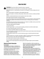
,_
WARNING:
This and/or
symbol property
points out
safety
instructions
which,
notinstructions
followed, could
the personal safety
of important
yourself and
others.
Read and
followif all
in thisendanger
manual
before attempting to operate this machine. Failure to comply with these instructions may result in personal
injury. When you see this symbol--HEED ITS WARNING.
WARNING:
Engine exhaust, some of its constituents, and certain vehicle components contain or emit
chemicals known to State of California to cause cancer and birth defects or other reproductive harm.
WARNING:
This machine was built to be operated according to the rules for safe operation in this
manual. As with any type of power equipment, carelessness or error on the part of the operator can result in
serious injury. This machine is capable of amputating hands and feet and throwing objects. Failure to
observe the following safety instructions could result in serious injury or death.
GeneralOperation
1.
2.
3.
4.
5.
6.
Read this operator's manual carefully in its entirety
before attempting to assemble this machine. Read,
understand, and follow all instructions on the
machine and in the manual(s) before operation. Be
completely familiar with the controls and the proper
use of this machine before operating it. Keep this
manual in a safe place for future and regular
reference and for ordering replacement parts.
This machine is a precision piece of power
equipment, not a plaything. Therefore, exercise
extreme caution at all times. Your unit has been
designed to perform one job: to mow grass. Do not
use it for any other purpose.
Never allow children under 14 years old to operate
this machine. Children 14 years old and over
should read and understand the operation
instructions and safety rules in this manual and
should be trained and supervised by a parent. Only
responsible individuals who are familiar with these
safe operation rules should use this machine.
Thoroughly inspect the area where equipment is to
be used. Remove all stones, sticks, wire, bones,
toys and other foreign objects which could be
tripped over or picked up and thrown by the blade.
Thrown objects can cause serious personal injury.
Plan your mowing pattern to avoid discharge of
material toward roads, sidewalks, bystanders and
the like. Also, avoid discharging material against a
walt or obstruction which may cause discharged
material to ricochet back toward the operator.
To help avoid blade contact or a thrown object
injury, stay in the operator zone behind the handles
and keep bystanders, helpers, children and pets at
least 75 feet from the machine while it is in
operation. Stop machine if anyone enters the area.
Always wear safety glasses to protect your eyes
during equipment operation and while performing
an adjustment or repair. Thrown objects which
ricochet can cause serious injury to the eyes.
7.
Wear sturdy, rough-soled work shoes and closefitting slacks and shirts. Shirts and pants that cover
the arms and legs and steel-toed shoes are
recommended. Never operate this machine in bare
feet, sandals, slippery or light weight (e.g. canvas)
shoes.
8.
Do not put hands or feet near rotating parts or
under the cutting deck. Contact with the blade can
amputate hands and feet.
9. A missing or damaged discharge cover can cause
blade contact or thrown object injuries.
10. Many injuries occur as a result of the mower being
pulled over the foot during a fall caused by slipping
or tripping. Do not hold on to the mower if you are
falling; release the handle immediately.
11. Never pull the mower back toward you while you
are walking. If you must back the mower away from
a walt or obstruction first look down and behind to
5.
6.
7.
8.
avoid tripping and then follow these steps:
a. Step back from the mower to fully extend
your arms.
b. Be sure you are well balanced with sure
footing.
c. Pull the mower back slowly, no more than
half way toward you.
d. Repeat these steps as needed.
Do not operate the mower while under the influence
of alcohol or drugs.
Do not engage the self-propelled mechanism on
units so equipped while starting engine.
The blade control handle is a safety device. Never
attempt to bypass its operation. Doing so makes
the safety device inoperative and may result in
personal injury through contact with the rotating
blade. The blade control handle must operate
easily in both directions and automatically return to
the disengaged position when released.
Never operate the mower in wet grass. Always be
sure of your footing. A slip and fall can cause
serious personal injury. If you feel you are losing
your footing, release the blade control handle
immediately
andthebladewillstoprotatingwithin
3. Do not mow on wet grass. Unstable footing could
threeseconds.
cause slipping.
9. Mowindaylightorgoodartificiallight;walk,notrun.
10.Stopthebladewhencrossinggraveldrives,
Children
walkways
or roads.
accidents can occur if the operator is not alert to
11. Iftheequipment
shouldstarttovibrateabnormally, Tragic
the presence of children. Children are often attracted to
stoptheengineandcheckimmediately
forthe
the mower and the mowing activity. They do not
cause.Vibrationisgenerallya warningoftrouble.
understand the dangers. Never assume that children
12.Shuttheengineoffandwaituntilthebladecomes
will remain where you last saw them.
toa completestopbeforeremoving
thegrass
1. Keep children out of the mowing area and under
catcherorunclogging
thechute.Thecuttingblade
the watchful care of a responsible adult other than
continues
torotateforafewsecondsafterthe
the operator.
engineisshutoff.Neverplaceanypartofthebody
2. Be alert and turn mower off if a child enters the
inthebladeareauntilyouaresurethebladehas
area.
stoppedrotating.
3.
Before and while moving backwards, look behind
13.Neveroperatemowerwithoutpropertrail shield,
and down for small children.
discharge
cover,grasscatcher,bladecontrol
4.
Use extreme care when approaching blind comers,
handleor othersafetyprotective
devicesinplace
doorways, shrubs, trees, or other objects that may
andworking.Neveroperatemowerwithdamaged
obscure your vision of a child who may run into the
safetydevices.Failuretodosocanresultin
mower.
personalinjury.
5.
Keep children away from hot or running engines.
14.Mufflerandenginebecomehotandcancausea
They can suffer bums from a hot muffler.
burn.Donottouch.
6.
Never allow children under 14 years old to operate
15.Only use parts and accessories made by the
original equipment manufacturer (O.E.M). Failure
to do so can result in personal injury.
16. If situations occur which are not covered in this
manual, use care and good judgment. Contact your
dealer for assistance. Call 1-877-282-8684 for the
name of your nearest dealer.
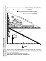
SlopeOperation
Slopes are a major factor related to slip and fall
accidents which can result in severe injury. Operation
on slopes requires extra caution. If you feel uneasy on a
slope, do not mow it. Before operating this unit on a
slope or hilly area, use the slope gauge on page 6 to
measure slopes. If the slope is greater than 15
degrees, do not mow it.
a power mower. Children 14 years old and over
should read and understand the operation
instructions and safety rules in this manual and
should be trained and supervised by a parent.
Service
Safe Handlingof Gasoline:
1.
2.
3.
4.
DO:
1.
2.
3.
Mow across the face of slopes; never up and down.
Exercise caution when changing direction.
Watch for holes, ruts, rocks, hidden objects, or
bumps which can cause you to slip or trip. Tall
grass can hide obstacles.
Always be sure of your footing. A slip and fall can
cause serious personal injury. If you feel you are
losing your balance, release the blade control
handle immediately, and the blade will stop rotating
within 3 seconds.
Do Net:
1.
2.
Do not mow near drop-offs, ditches or
embankments, you could lose your footing or
balance.
Do not mow slopes greater than 15 degrees as
shown on the slope gauge.
5.
6.
7.
8.
9.
To avoid personal injury or property damage use
extreme care in handling gasoline. Gasoline is
extremely flammable and the vapors are explosive.
Serious personal injury can occur when gasoline is
spilled on yourself or your clothes which can ignite.
Wash your skin and change clothes immediately.
Use only an approved gasoline container.
Never fill containers inside a vehicle or on a truck or
trailer bed with a plastic liner. Always place
containers on the ground away from your vehicle
before filling.
If possible, remove gas-powered equipment from
the truck or trailer and refuel it on the ground. If this
is not possible, then refuel such equipment on a
trailer with a portable container, rather than from a
gasoline dispenser nozzle.
Keep the nozzle in contact with the rim of the fuel
tank or container opening at all times until fueling is
complete. Do not use a nozzle lock-open device.
Extinguish all cigarettes, cigars, pipes and other
sources of ignition.
Never fuel machine indoors because flammable
vapors will accumulate in the area.
Never remove gas cap or add fuel while the engine
is hot or running. Allow engine to cool at least two
minutes before refueling.
10.Neveroverfillfueltank.Filltankto nomorethan½
inchbelowbottomoffillernecktoprovidespacefor
fuelexpansion.
11.Replacegasolinecapandtightensecurely.
12. Ifgasolineisspilled,wipeitofftheengineand
equipment.
Moveunittoanotherarea.Wait5
minutesbeforestartingtheengine.
13.Neverstorethemachineorfuelcontainerinside
wherethereisanopenflame,sparkorpilotlightas
onawaterheater,spaceheater,furnace,clothes
dryerorothergasappliances.
14.Toreducefirehazard,keepmowerfreeofgrass,
leaves,orotherdebrisbuild-up.Cleanupoilorfuel
spillageandremoveanyfuelsoakeddebris.
15.Allowmowertocool5 minutesbeforestoring.
GeneralService:
1.
2.
3.
Never run an engine indoors or in a poorly
ventilated area. Engine exhaust contains carbon
monoxide, an odorless and deadly gas.
Before cleaning, repairing, or inspecting, make
certain the blade and all moving parts have
stopped. Disconnect the spark plug wire and
ground against the engine to prevent unintended
starting.
Check the blade and engine mounting bolts at
frequent intervals for proper tightness. Also,
visually inspect blade for damage (e.g., bent,
cracked, worn) Replace blade with the original
equipment manufacture's (O.E.M.) blade only,
listed in this manual. "Use of parts which do not
meet the original equipment specifications may
lead to improper performance and compromise
safety!"
4.
Mower blades are sharp and can cut. Wrap the
blade or wear gloves, and use extra caution when
servicing them.
5. Keep all nuts, bolts, and screws tight to be sure the
equipment is in safe working condition.
6. Never tamper with safety devices. Check their
proper operation regularly.
7. After striking a foreign object, stop the engine,
disconnect the spark plug wire and ground against
the engine. Thoroughly inspect the mower for any
damage. Repair the damage before starting and
operating the mower.
8. Never attempt to make a wheel or cutting height
adjustment while the engine is running.
9. Grass catcher components, discharge cover, and
trail shield are subject to wear and damage which
could expose moving parts or allow objects to be
thrown. For safety protection, frequently check
components and replace immediately with original
equipment manufacturer's (O.E.M.) parts only,
listed here. Use of parts which do not meet the
original equipment specifications may lead to
improper performance and compromise safety.
10. Do not change the engine governor setting or
overspeed the engine. The governor controls the
maximum safe operating speed of the engine.
11. Maintain or replace safety and instruction labels, as
necessary.
12. Observe proper disposal laws and regulations.
Improper disposal of fluids and materials can harm
the environment.
YourResponsibility
Restrict the use of this power machine to persons who read, understand and follow the warnings and
instructions in this manual and on the machine.
/ WARNING
SIGHT AND HOLD THIS LEVEL WITH A VERTICAL TREE
C
A POWER POLE
A CORNER OF A BUILDING
o
"" ~....
i
,q
i
OR A FENCE POST
iq
O
c
O
t_
co
03
¢0
O.
O
CO
E
t.O
l
O
0_
o.
I,U
_o
I,M
"_
.=.°
5
WARNING
co
O_1
03
CO
.
_
Do not mow on inclines with a slope in excess of 15 degrees (a rise of approximately 2-1/2 feet every 10 feet). A riding mower could
CO O
o.--
._
_
=_ _
o
and
you could
slip, resulting
in serious
injury. a walk-behind mower on such a slope, it is extremely difficult to maintain your footing
overturn
and cause
sedoasupinjury.
If operating
Operate RIDING
mowers
and down
slopes, never across the face of slopes.
_ Co_
o
Operate WALK-BEHIND
03
mowers across the face of slopes, never up and down slopes.
SECTION3: ASSEMBLING
YOURLAWNMOWER
RemovingUnitFromCarton
Remove staples, break glue on top flaps, or cut
tape at carton end and peel along top flap to open
carton.
Remove loose parts, if included with unit (i.e., grass
bag etc.), and save it appropriately.
Cut along corners, lay the carton down flat, and
remove all packing material.
Roll or slide unit out of carton and check carton
SettingUpYourLawnMower
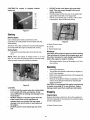
AssemblingHandle
Lift up and pull back on the upper handle to raise
the handle into the operating position. See Figure
3. Make certain the lower handle is seated securely
into the handle bracket assemblies.
Handle Assembly
thoroughly for loose parts.
LoosePartsin Carton
1.
2.
3.
4.
Grass Bag
Grass Bag Adapter
Side Discharge Chute
Hardware Pack
Wing I_ut
Handle Mountin
Bracket
HardwarePack
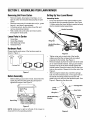
Please identify each piece of the hardware pack as
shown in Figure 1.
Ca a0e0ot
Wing Nut
Figure 1
BeforeAssembly
Before setting up your lawn mower, disconnect the
spark plug wire from the spark plug and ground
against the engine. See Figure 2.
Figure 3
Tighten wing nuts on each side of the handle
making sure that the carriage bolts are seated
propedy into the handle. See Figure 3.
Remove hairpin clip from the outer hole of the weld
pin on each handle brackets. Using a pair of pliers,
squeeze one leg of the lower handle against the
handle bracket. Insert the hairpin clip into the inner
hole on the weld pin. Repeat on the other side. See
Figure 4.
After moving the hairpin clip, insert the cardage
bolt, from the hardware pack, in the upper hole on
the handle mounting bracket and secure with
plastic wing nut, also from the hardware pack. See
Figure 4. Repeat on the other side.
\
_.,=-----Carriage
Lower
Handle
Wing
Handle Mounting
Bracket
Clip
Figure 2
NOTE: Reference to right or left side of the mower is
observed from the operating position.
Figure 4
Bolt
Fastenthecabletothelowerhandlewiththetwo
cabletiesfoundonthelowerhandle.Pullthecable
tiestightandtrimofftheexcess.SeeFigure5.
Grass Bag
Cable Tie.
Handle
Nuts
Figure5
Figure7
AttachingStarterRope
Lift chutedooron the grass bag adapter and slide
grass bag onto the adapter. See Figure8.
NOTE: Make certain the drive cable is routed around
the outside and above the lower handle so it does not
interfere with attaching the grass bag.
NOTE: The chute door has been designed to move the
starter rope out of the way of the bag when the chute
door is opened.
The rope guide, which is connected to the support
rod, is located on the right side of the lower handle.
See Figure 6.
With the spark plug wire disconnected and
grounded, hold the blade control handle against the
upper handle, and pull the starter rope out of the
engine. Release the blade control handle. Slip the
starter rope into the rope guide.
Sta_er
Rope
Figure 8
Rod
Guide
Figure 6
AttachingSideDischargeChute
Remove mulching baffle or grass bag adapter from
unit by disconnecting wing nuts.
Attach side discharge chute to unit and secure with
the three wing nuts. See Figure 9.
AttachingTheGrassBag
The mower was shipped with the mulching baffle
installed on the unit. You can keep this baffle on as long
as you want to mulch the grass clippings. For bagging
purposes, you will have to attach the grass bag and its
adapter in place of the mulching baffle.
Remove three wing nuts holding the mulching
baffle or side discharge chute in place and remove
the accessory from the unit.
Replace with grass bag adapter, while making
sure the front lip of adapter goes under the edge of
the deck. Secure with wing nuts previously
removed. See Figure 7.
Side Discharge
Chu_
Nuts
Figure 9
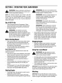
SECTION4: KNOWYOURLAWNMOWER
Read this operator's manual and safety rules before
operating your lawn mower. Compare the illustration in
Figure 10 with your lawn mower to familiarize yourself
with the location of various controls and adjustments.
Save this manual for future reference.
_
WARNING:
The operation of any lawn
mower can result in foreign objects being
thrown into the eyes, which can damage your
eyes severely. Always wear safety glasses
while operating the mower, or while performing
any adjustments or repairs on it.
Blade ControlHandle
The blade control handle is located on the upper handle
of the mower. The blade control handle must be
depressed in order to operate the unit. Release blade
control handle to stop engine and blade.
_bb
WARNING:
This blade control mechanism is
a safety device. Never attempt to bypass its
operations.
CuttingHeightAdjustmentLevers
The cutting height adjustment lever is located above
the left rear wheel. To adjust the cutting height, refer to
the Adjustment Section in this manual.
Recoil Starter
The recoil starter is attached to the right upper handle.
Stand behind the unit and pull the recoil starter rope to
start the unit.
Drive Clutch Lever
Drive ClutchControl
The drive clutch control is located on the upper handle.
Squeeze the drive control to engage the drive system.
Release the clutch control to disengage the drive
system. Release the clutch control to slow down when
approaching an obstacle, making a turn, or stopping..
Shift Lever
The shift lever is located on the drive clutch control
housing on the upper handle. This lever is used to
select the forward speed of the mower. When changing
speed selection, release the drive clutch lever.
NOTE: Move the shift lever only when the engine is
running. Changing the shift lever setting with the engine
off can damage the mower.
GrassBag
The grass bag is equipped with a bag-fill indicator to
add convenience to your work. While the mower is
running, air will flow through the bag and into the Grass
Gauge. If the grass catcher is empty, air flows through
easily pushing the gauge up. If the grass catcher is full,
air does not flow through it allowing the gauge to fall. So
the position of the gauge acts as a bag-fill indicator
signifying when to empty the grass bag.
MulchingPlug
The mulching plug is used only for mulching purposes.
Instead of collecting grass clippings in a grass catcher,
this mower has the option of recirculating the clippings
back to the lawn.
e Control Handle
Grass
Catcher
Shift Lever
Recoil
Trail Shield
Side-Discharge
Chute
Mulch Plug
Figure 10
Height Adjustment
Lever
SECTION5: OPERATING
YOURLAWNMOWER
,_
il_
WARNING:
understand,
and follow
all
instructions andRead,
warnings
on the machine
and
WARNING:
Be sure no one other than the
operator is standing near the lawn mower while
starting engine or operating mower.
in this manual before operating.
NOTE: For shipping purposes your mower is set with
the wheels in a low cutting height position. For best
results, raise the cutting position until it is determined
which height is best for your lawn. See the Adjustment
Section for details.
WARNING:
Never run engine indoors or in
enclosed, poorly ventilated areas. Engine
exhaust contains carbon monoxide, an
odorless and deadly gas.
Gas& OilFill-Up
WARNING:
Keep hands, feet, hair and
loose clothing away from any moving parts on
engine and lawn mower.
Check oil level and add oil if necessary. Follow
relevant instructions in the engine manual for this.
Service the engine with gasoline as instructed in
the engine manual.
,_
WARNING:
When starting the unit for the
first time, face the mower against a wall or a
fence. Start the unit and if it shows any signs of
motion while the drive clutch control is still
disengaged, shut engine off immediately.
WARNING:
Use Gasoline
extreme care
when
handling gasoline.
is extremely
Grasp starter handle and pull rope out slowly until
engine reaches start of compression cycle (rope
will pull slightly harder at this point). Let the rope
rewind slowly. Pull rope with a rapid, continuous,
full arm stroke. Keeping a firm grip on the starter
handle, let the rope rewind slowly.
flammable and the vapors are explosive. Never
fuel the machine indoors or while the engine is
hot or running. Extinguish cigarettes, cigars,
pipes and other sources of ignition.
BeforeStartingMower
Attach spark plug wire to spark plug. Make certain
the metal cap on the end of the spark plug wire
(inside the rubber boot) is fastened securely over
the metal tip on the spark plug.
Check for proper drive clutch operation using the
neutral adjustment test described below.
StoppingEngine
Release the blade control handle to stop engine
and blade. Wait till the blade stops completely.
Disconnect spark plug wire and move away from
spark plug to prevent accidental starting.
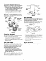
Neutral AdjustmentTest
UsingYourLawnMower
To perform the neutral adjustment test, answer the
following questions.
_lb
With the drive clutch control released, push mower
forward and pull it backward. Does it move freely?
Squeeze the drive clutch control and pull the
mower backward. Do the rear wheels lock?
Is the drive clutch control cable free of kinks or
WARNING:
Do not operate the mower
without mulching baffle, discharge chute or
grass catcher propedy installed.
For best results, do not cut wet grass. It may stick to
the underside of the mower, preventing proper
discharge of grass clippings, and could cause you
to slip and fall. New grass or thick grass may
require a narrower cut.
For a healthy lawn, always cut off one-third or less
of the total length of the grass.
sharp bends?
If you answered "yes" to all three questions, your
mower passed the test and you can start your
mower.
If you answered "no" to any of the three questions,
you will have to adjust the drive clutch control as
instructed in the ADJUSTMENT SECTION.
IMPORTANT: Move the shift lever only when the engine
is running. Changing the shift lever setting with the
engine off can cause damage to the mower.
StartingEngine
Mulching
Push primer once. Do not prime to restart a warm
engine after a short shutdown.
Standing behind the mower, depress the blade
control handle and hold it against the upper handle.
IMPORTANT: Be sure that the lawn is clear of stones,
sticks, wire, or other objects which could damage lawn
mower or engine. Such objects could be accidently
10
thrownbythemowerinanydirectionandcauseserious
personalinjurytotheoperatorandothers.
_
WARNING:
Attach grass catcher following instructions on page
8 of this manual. Grass clippings will automatically
collect in the bag as you run the mower.
Operate the mower till the grass bag is full.
Stop engine completely by releasing the blade
control handle. Make sure that the unit has come to
If the mower strikes a foreign
object, stop the engine. Remove spark plug
wire from the spark plug and thoroughly inspect
for any damage. Repair the damage promptly
before restarting and operating the mower.
a complete stop.
While holding the grass bag by both the rear handle
and the lower handle, lift the grass bag straight up
off the adapter. The chute door will move the rope
out of the way of the bag.
Continue to hold the lower handle and raise the
For effective mulching, do not cut wet grass. New or
thick grass may require a narrower cut. If the grass has
grown in excess of 4", mulching is not recommended.
Mow using the side discharge to reduce the grass
height to 3.25" maximum before mulching.
rear of the grass bag up toward your chest. The
grass bag will open and the grass clippings will
disperse. When replacing the grass bag, be sure
the top of the bag rests on the wire support
between the handles.
BaggingGrassClippings
You can use the grass catcher bag to collect clippings
while you are operating the mower.
SECTION6: MAKINGADJUSTMENTS
_lb
WARNING:
Reassemble the handles, placing the bottom holes
in the handle over the weld pins in the handle
mounting bracket.
Place the hairpin clips in the inner holes in the weld
pins and insert the carriage bolts through the upper
hole on the handle mounting bracket and secure
with plastic wing nuts.
Reassemble the upper handle to the lower handle.
Attach the starter rope as instructed on page 8.
DO not at any time make any
adjustments without first stopping engine and
disconnecting spark plug wire.
HandleHeight
Your mower is shipped with the handle in the higher
height position. To lower the height, proceed as follows:
Remove the starter rope from the rope guide.
Remove the wing nuts and carriage bolts securing
the upper handle. Remove and lay the upper
handle out of the way, being careful not to bend or
kink the cables.
CuttingHeight
Your mower is shipped with the cutting height in the
lowest position. To adjust the rear cutting height,
proceed as follows:
Remove the hairpin clips from the weld pins on the
handle brackets and remove the wing nuts and
carriage bolts from the upper hole on the handle
mounting bracket.
Press out on the legs of the lower handle and
remove lower handle from the mower.
Turn lower handle around so the notch on the
Pull the rear height adjustment lever out and away
from the mower and then move it forward or
backward to another slot. For rough or uneven
lawns, move the height adjustment lever to a higher
position. This will help stop scalping. See Figure 12.
,_ear
bottom of the lower handle is facing forward.
See Figure 11.
\
Notch
Lower Handle
Left Rear Wh__
Figure 12
Figure 11
11
Height Adj,.Lever
The front wheel cutting height is determined by
selecting one of six positions on each caster assembly.
To adjust front cutting height, proceed as follows:
Bottom View
®
Remove the wing nut from the axle bolt. See Figure
13. Slide the axle bolt and spring washer from the
assembly and select a cutting height.
With the spring washer on the axle bolt, reinsert
hardware in the square hole desired through the
wheel assembly and secure with the wing nut
previously removed.
Adjustment
Handle
Wheel_
Shift Lever
IMPORTANT: All wheels must be placed in the same
relative position. For rough or uneven lawns, raise the
cutting height of your mower.
Caster
Caster
Lock
Lock
Pin
Pin
Square Hole
(indicates
various cutting
Wheel
Front
®
Figure
e Clutch
Control
14
ShiftLeverCable
Pedodic adjustment of the six speed shift cable may be
necessary due to normal wear on the cable. Adjustment
is needed if all six speeds do not work.
The adjustable cable bracket is located on the left side
of the mower beside the engine. See Figure 15.
he ghts)
Adjustable Cable
Bracket
Hex Nut
Wing
Front ./_
Wheel
Spring
Washer
Figure 13
Figure 15
CasterLockAdjustment
Start engine and place shift lever in the sixth speed
position. Stop engine and disconnect spark plug
wire and ground it against engine.
Loosen hex nut which secures the adjustable cable
bracket. See Figure 15.
Push back on the adjustable cable bracket and
tighten hex nut.
The casters can be locked in a straight ahead position
or position to swivel freely. See Figure 13.
Lift and place the lock pins in the larger holes to
lock the wheels for straight ahead operation.
Place pins in smaller holes to allow casters to rotate
freely for turning.
DriveClutchControl
EngineAdjustments
The adjustment wheel is located in the drive clutch
control handle housing and is used to tighten or loosen
the drive belt. You will have to adjust the drive clutch
control if, with the drive clutch engaged, the mower
either does not self-propel or hesitate.
Refer to the engine manual for these adjustments.
To resolve the above problems, rotate the
adjustment wheel with your fingers: clockwise to
tighten the cable and counter-clockwise to loosen
the cable. See Figure 14.
NOTE: For some operators, the drive clutch control
may not be in a comfortable position. You can adjust
the handle out by tightening the adjustment wheel.
12
SECTION7: MAINTAINING
YOURLAWNMOWER
_lb
WARNING:
Inspect muffler periodically, and replace if
necessary. Damaged mufflers or spark arresters
can create a fire hazard. Make sure to avoid muffler
Always stop the engine and
disconnect the spark plug wire before
performing any maintenance work or
adjustments on your lawn mower.
and surrounding areas while the mower engine is
hot because temperature of these areas of the
engine may exceed 150° F.
CleaningMower
The underside of the mower deck should be cleaned
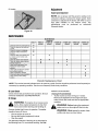
Lubrication
after each use to prevent any build-up of debds. If
allowed to accumulate, it will cause rust and corrosion.
Refer to the lubrication chart in Figure 16.
BladeControlHandle
NOTE: We do not recommend the use of pressure
washers or garden hose to clean your unit. These may
cause damage to electric components, spindles,
pulleys, bearings, or the engine. The use of water will
result in shortened life and reduce serviceability.
Lubricate the pivot points on the blade control
handle at least once a season with light oil. The
blade control must operate freely in both directions.
Rear DischargeDoor
Lubricate the torsion spring and the pivot point on
each end of the rear discharge door using a light oil.
This will prevent rusting of the discharge door.
Disconnect spark plug wire.
Drain the gasoline from the lawn mower, or place a
piece of plastic under the gas cap.
Tip the mower so that it rests on the housing. Keep
the side with the air cleaner facing up. Hold the
mower firmly.
Scrape and clean the underside of the deck with a
suitable tool. Do not spray with water.
Put the mower back on its wheels on the ground. If
you had put plastic under the gas cap, make sure to
remove it now.
_lb
WARNING:
Wheels
Lubricate the wheels and bearings, if so equipped,
at least once a season with light oil or engine oil.
Also, if the wheels are removed for any reason,
lubricate the surface of the axle bolt and the inner
surface of the wheel with light oil.
Engine
Follow the engine manual instructions and
recommended schedule for lubricating engine
components.
Never tip the mower more than
90 degrees in any directions and do not leave
the mower tipped for any length of time. Oil can
drain into the upper part of the engine causing
a starting problem.
EngineCare
Lubricate
A list of key maintenance jobs required for good
performance by the mower is given below. Follow the
accompanying engine manual for detailed list and
instructions.
Lubricate
Lubricate
Change engine oil regularly, as instructed in the
engine manual. Check oit level before starting
engine every time. Change oit while the engine is
warm, not hot or cold.
Service foam filter in the air cleaner every 25 hours
of use and replace the paper filter component every
100 hours. You may have to service the air filter
more frequently if you are operating the mower
under extremely dusty conditions.
Clean the engine periodically. Remove dirt and
debris with a cloth or brush.
Lubricate
Lubricate
Clean the spark plug and reset the gap to .030" at
least once a season. Refer to the engine manual for
correct spark plug type.
Figure 16: Lubrication Chart
13
SECTION8: SERVICING
THEMOWER
_1=
WARNING:
Place the blade on the adapter. Be certain the
blade is aligned and seated on the blade adapter
flanges.
Place blade bell support on blade. Make sure the
notches on the blade bell support are aligned with
small holes in the blade.
Always stop the engine and
disconnect the spark plug wire before
performing any maintenance work or
adjustments on your lawn mower.
BladeCare
_
WARNING:
Replace hex bolt and tighten hex bolt to torque: 450
in. lbs. min., 600 in. lbs. max.
When removing the cutting
NOTE: To ensure safe operation of your mower,
periodically check the blade bolt for correct torque.
blade for sharpening or replacement, protect
your hands with a pair of heavy gloves or use a
heavy rag to hold the blade.
Blade
Periodically inspect the blade adapter for cracks,
especially if you strike a foreign object. Replace when
necessary.
Blade Bell
Removingthe Blade
Disconnect spark plug wire from spark plug.
Turn mower on its side making sure that the air filter
and the carburetor are up.
Remove the bolt and the blade bell support which
hold the blade and the blade adapter to the engine
crankshaft. See Figure 17.
Remove the blade and the adapter from the
crankshaft.
Support
Figure 17
DriveBeltReplacement
Sharpeningthe Blade
The blade can be sharpened with a file or on a
grinding wheel. Do not attempt to sharpen the
blade while it is still on the mower.
Disconnect the spark plug wire and ground it
against the engine.
Drain the fuel tank or place a piece of plastic
beneath the cap to prevent gasoline leakage.
Place shift lever in the first position and tip the
mower on its side with air filter facing up.
Remove the center bolt which secures the blade to
Follow the original angle of grind as a guide. Make
sure that each cutting edge receives an equal
amount of gdnding to prevent an unbalanced blade.
_
the crankshaft followed by blade bell support,
blade, and blade adapter.
Move the cutting height adjustment to the highest
position.
Remove the three hex screws holding the baffle to
the deck and pivot baffle towards the rear of the
mower. See Figure 18.
WARNING:
An unbalanced
blade
wilt cause
excessive vibration
when rotating
at high
speeds. It may cause damage to the mower,
and could break causing personal injury.
Balancingthe Blade
The blade can be tested by balancing it on a round
shaft screwddver. Remove metal from the heavy
side until it balances evenly. It is recommended that
the blade always be removed from the adapter
when testing for balance.
Installingthe Blade
Before reinstalling the blade and the blade adapter
to the unit, lubricate the engine crankshaft and the
inner surface of the blade adapter with light oil.
Be sure to install the blade with the side of the
blade marked "Bottom" (or with part number) facing
the ground when the mower is in the operating
position.
Slide the blade adapter onto the engine crankshaft.
Baffle
Figure 18
14
Remove the hex bolt from the rear of unit holding
the transmission to the mower housing.
See Figure 19.
Pivot the control arm down away from the pulley
and belt.
Lift off the lower pulley assembly and remove the
old belt from around the crankshaft.
Place the new belt over the transmission pulley.
Start the belt in the pulley groove and rotate the
pulley until the belt is seated in transmission pulley.
Place the belt between the idler pulley and the belt
keeper bracket.
Using pliers, rotate the belt keeper bracket so that it
snaps into slot on the idler bracket.
Tighten the idler pulley bolt and lock nut half a turn.
Place the belt between the two pulley halves on the
crankshaft. Make sure to route the belt inside the
Whee_..._
/Hex
Cutting Height
__i
Adjustment
Z_1_1, _ I,
Bolt
belt guard pin. See Figure 22.
Figure 19
Upper Pulley_///__
Tilt the transmission forward and loosen the idler
pulley bolt and lock nut half a turn. See Figure 20.
Half Tab
( I_/'//_')'_
Transmission
Pulley
Belt
Belt
Belt
Belt Keeper
Bracket
Guard Pin_
_
LOal"_er
Pulley
__
-'
Figure 22
Idler
Pulley
IMPORTANT:When replacing the belt, do not disassemble the lower pulley assembly.
Bolt a
Locknut
Pinch both sides of the belt together so that the belt
is not in the pulley groove, and the lower pulley can
be pushed towards the engine. See Figure 23.
Figure 20
Using a pair of pliers, pull back and rotate belt
keeper bracket from the slot on the idler pulley.
Slide the belt out from between the belt keeper
bracket and the idler pulley.See Figure 20.
Squeeze the belt together and push it forward,
while pressing the control arm inward towards the
deck and remove the six speed cable from the slot.
See Figure 21.
Six*Speed
Cable Slot
Lower Pulley
o
o
Belt
Belt
Guard Pin
Arm
Figure 23
Pivot the control arm back to its original position
and reinstall the six-speed cable into the slot.
See Figure 24.
Figure 21
15
Attach the new flap and new rod to deck, bending
the ends of the new rod over to secure to deck.
Six-Speed
ReplacingBatteryPack
(Model E977 only)
Remove the battery pack from the handle panel for
replacement only. Do not separate the batteries for
any reason. Dispose of batteries properly.
When replacing battery pack in handle panel,
battery pack must be positioned with the positive
terminal to the right side and the negative terminal
to the left side of the panel. Replacing the battery
pack incorrectly will cause serious damage. The
positive lead on the wire harness has the smaller
connector. Connect the positive lead to the positive
side of the battery pack, then connect the negative
side.
Control
Arm
Figure 24
Make sure the belt is routed inside the pulley halves
and the belt guard pin.
Reinstall the bolt securing transmission to rear
mower housing.
Pivot the baffle back to its original position and
secure with three hex screws removed earlier.
_
WARNING:
Batteries
sulfuric
acid or
which may cause
burns. contain
Do not short
circuit
mutilate batteries in any way. Do not put
batteries in fire as these may burst or release
toxic materials.
Lightly lubricate the inside of the blade adapter and
reinstall the spacer, wave washer, blade adapter
assembly, and blade in the correct order.
Tighten the hex bolt to secure the blade to torque:
450-600 in. Ibs.
In-lineFuse
(Model E977 only)
The unit is equipped with an in-line fuse. If the unit fails
to start, check the fuse inside the battery cover by
turning the end of the fuse holder and removing from
the battery cover. Replace with standard automotive 71/2 amp fuse.
ReplacingRearFlap
To remove rear flap, cut off the flat end of the wire
rod which secures it to the deck.
SECTION9: OFF-SEASON
STORAGE
Coat mower's cutting blade with chassis grease to
prevent rusting.
Store mower in a dry, clean area. Do not store next
to corrosive materials, such as fertilizer.
StoringYourLawnMower
The following steps should be taken to prepare your
lawn mower for storage.
Clean and lubricate mower thoroughly as described
in the lubrication instructions.
NOTE: When storing any type of power equipment in a
poorly ventilated or metal storage shed, care should be
taken to rust-praof the equipment. Using a light oil or
silicone, coat the equipment, especially cables and all
moving parts.
IMPORTANT: We do not recommend the use of a
pressure washer or garden hose to clean your unit.
Refer to engine manual for correct engine storage
instructions.
16
SECTION
10: TROUBLESHOOTING
Problem
Cause
Remedy
Engine fails to start
1.
2.
3.
4.
5.
6.
Blade control handle disengaged.
Spark plug wire disconnected.
Fuel tank empty or stale fuel.
Blocked fuel line.
Faulty spark plug.
Engine flooded
1.
2.
3.
4.
5.
6.
Engage blade control handle.
Connect wire to spark plug.
Fill tank with clean, fresh gasoline.
Clean fuelline.
Clean, adjust gap, or replace.
Wait a few minutes to restart, do not
prime.
Engine runs erratic
1.
2.
Spark plug wire loose.
Blocked fuel line or stale fuel.
1.
2.
3.
4.
5.
6.
Vent in gas plugged.
Water or dirt in fuel system.
Dirty air cleaner.
Carburetor out of adjustment.
3.
4.
5.
6.
Connect and tighten spark plug wire.
Clean fuel line; fill tank with clean, fresh
gasoline
Clear vent.
Drain fuel tank. Refill with fresh fuel.
Clean air cleaner.
Adjust carburetor.
Engine overheats
1.
2.
3.
Engine oil level low.
Air flow restricted.
Carburetor not adjusted properly.
1.
2.
3.
Fill crankcase with proper oil.
Remove blower housing and clean.
Adjust carburetor.
Occasional skip (hesitates)
at high speed
1.
Spark plug gap too close.
1.
Adjust gap to.030".
Idles poorly
1.
2.
3.
Spark plug fouled, faulty or gap too
wide.
Carburetor improperly adjusted.
Dirty air cleaner.
1.
2.
3.
Reset gap to .030" or replace spark plug.
Adjust carburetor.
Clean air cleaner.
1.
2.
Cutting blade loose or unbalanced.
Bent cutting blade,
1.
Tighten blade and adapter. Balance
blade.
Replace blade.
Excessive vibration
2.
Mower will not mulch grass
Uneven cut
1.
Wet grass.
1.
2.
Excessively high grass.
2.
3.
Dull blade.
3.
1.
Wheels not positioned correctly.
1.
2.
Dull blade.
2.
Do not mow when grass is wet; wait until
later to cut.
Mow once at a high cutting height, then
mow again at desired height or make a
narrower cutting path.
Sharpen or replace blade.
Place all four wheels in same height
position.
Sharpen or replace blade.
NOTE: For repairs beyond the minor adjustments listed above, contact your local authorized service dealer.
17
YOURNOTES
Date
Comments
I
18
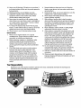
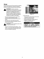
Safety& DecorativeLabels
Some of the labels found on your mower are representeted here with the corresponding part numbers. Please use
these part numbers when ordering replacement labels.
777S30118
DANGER
777120291
777S30128
777S30145
777D06697
DANGER
19
777S30116
SECTION
11: PARTSLISTFORMODEL997
20
100
48
27
29
59
\
_3
99
78
8
IMPORTANT:
For
a
proper
working
machine, use Factory Approved Parts.
V-BELTS are specially designed to engage
and disengage safely.
A substitute (non
OEM) V-Belt can be dangerous
by not
disengaging completely.
20
Model997
ReL
No.
1,
547-00408
Control Handle
2,
3,
4,
131-0904A
16864
731-0620
5,
6,
7,
713-0397
132-0627
731-0924
Upper Control Handle
6 Spd. Rack Cable Bracket
Control Lever
Gear Insert
8,
9,
10,
131-0905A
110-1667A
731-0906
11,
12,
13,
146-0711B
112-0324
146-0883
14,
15,
16,
17,
18,
19,
20,
21,
27,
28,
29,
30,
31,
32,
33,
34,
35,
36,
37,
38,
39,
40,
41,
42,
43,
44,
45,
46,
47,
48,
49,
50,
51,
52,
710-1270
746-04109
149-0439D
720-0284
136-0451
710-1174
726-0240
149-0907B
731-1901
732-0842
531-0066
731-1832
731-1833
182-0078B
712-0397
710-0703
746-0939
182-7574A
736-0270
712-0287
710-0167
112-0138
182-7575A
136-0329
156-0625
138-0924
736-0264
714-0104
732-0306
134-1981A
712-0414
16855
10622B
748-0381
148-0188B
138-0137A
748-0318
53,
54,
Part No.
Ref.
No.
Description
55,
56,
57,
58,
59,
60,
Shift Lever Spring
6 Speed Shift Lever
Top Lock Nut 1/4-20
Control Housing
Oval C-Sunk Screw
Control Cable 49"
Upper Handle
Wing Nut
Saddle Washer ,320 ID x .830 OD
Carriage Bolt 5/16-18 x 2.0
Cable Tie
Lower Handle
Trail Shield
Trail Shield Wire
Chute Assembly
Side-Discharge Chute
Mulch Cover
Deck 21"
Wing Nut
Carriage Bolt 1/4-20 x ,75
6 Speed Cable
Cable Adjustment Bracket
Bell Washer ,265 ID x .75 OD
Hex Nut 1/4-20
Carriage Screw 1/4-20 x ,50
Hex Nut 1/4-28
Cable Mounting Bracket
Lock Washer 1/4
Roller Cable
Shoulder Screw .375 ID x 1/4-14
Flat Washer .330 ID x ,630 OD
Cotter Pin
Compresion Spring
Wheel 9 x 2
Top Lock Tab Weld Nut 1/4-20
Ratchet Pawl Plate
Plastic Spring Ratchet
Pawl RH
Pawl LH
Shld Screw .340 ID x ,285 OD
Wheel Rachet
62,
63,
64,
65,
66,
67,
68,
69,
70,
71,
72,
73,
710-0260
754@460
656-0613
74,
75,
76,
750-1071
750-1070
782-7597
77,
78,
79,
710-0654A
782-7596
732-0807
80,
81,
82,
711-1114
736-6526
731-1828
83,
84,
85,
710-0653
753-0609
742-0741
86,
87,
88,
736-0524A
710-1257
731-1874
Blade Adapter Kit
21" Mulching Blade
Blade Bell Support
Hex Bolt 3/8-24 x 2,5
Chute Door
89,
90,
91,
732-0819
726-0111
747-0965
Torsion Spring
Push Cap
Pivot Rod
92,
94,
95,
731-1713B
726-0214
736-0366
Discharge Chute
Push Cap
Flat Washer.640 ID x 1,12 OD
96,
97,
98,
741-0685
712-3604A
734-1857
Flange Bearing
Flange Lock Nut 5/16-18
Wheel 7 x 2
99,
100,
101,
731-1888
731-0982A
682-3052
Hubcap - Spoke w/Hole
Hubcap - Radial Spoke
682-3053
21
Description
736-0270
710-6751
737-3000
736-6931
747-0924
682-9020A
682-9021 A
682-9624
682-9026
710-1348
710-6896
710-6654A
711-1146
736-0204
710-6703
710-1242
736-6232
712-0397
61,
Lower Control Housing
C Sunk Tap Screw #10 x ,75 Lg
Cable Mounting Cap
Drive Cable 51,0
Part No.
Bell Washer ,265 ID x ,75 OD
Hex Cap Screw 1/4-20 x ,620
Grease Fitting
Flat Washer .203 ID x ,403 OD
Wheel Pin Lock
Caster Assembly RH
Caster Assembly LH
Caster Bracket Assembly RH
Caster Bracket Assembly LH
Screw 1/4-14 x ,500
Screw 1/4-14 x ,625
Hex Washer Screw 3/8-16 x 1.0
Caster Axle
Flat Washer ,344 ID x ,62 OD
Carriage Screw 1/4-20 x ,75
Torx Screw
Wave Washer .531 ID x .781 OD
Wing Nut
Carriage Bolt 5/16-18 x .62
Belt 3/8 x 39.24
Pulley Assembly
Sleeve Spacer ,88 ID x 1.13 OD
Sleeve Spacer ,88 ID x 1,00 OD
Pivot Bracket
Screw 3/8-18 x 1,0
Control Arm
Torsion Spring
Pivot Shaft
Wave Washer 1.38 ID x .88 OD
Baffle
Screw 1/4-20 x 3,75
Handle Bracket Assembly- RH
Handle Bracket Assembly - LH
Model997
15
!
/
\
\
24.
\
8
"1o
\
12
31
6,
I
62
22
Model997
Ref.
No.
Part No.
Ref.
No.
Part Description
Part No.
Part Description
1.
2.
720-0223
732-0803A
Grip
32.
736-3084
Flat Washer .510 ID x 1.120 OD
Spring Lever
33.
712-0896
Hex Jam Nut 1/4-28
3.
738-0529
Shoulder Nut .825 x.165 Lg.
34.
782-7598
Belt Keeper
4.
5.
710-0751
736-0270
Cap Screw 1/4-20 x .620
Bell Washer .285 ID x .75 OD
35.
741-0600
Bearing
36.
732-6849A
Extension Spring
6.
7.
748-0318
736-0369
Wheel Rachet
Flat Washer ,508 ID x 1.00D
37.
38.
750-1050
682-6027A
Flange Spacer
Idler Bracket Assembly
8.
782-0566B
Pivot Arm Assembly
39.
710-0299
Hex Cap Screw 1/4-28 x 1.0
9.
750-0515
Spacer ,510 ID x .70 OD
46,
741-6682A
10.
741-0978
41.
42,
736-0570
721-6329
Bearing Sleeve
Flat Washer .865 ID x 1.45 OD
11.
750-1056
Sleeve Bearing .504 ID x .830 OD
Shoulder
12.
710-0653
Tap Screw I/4-20 x .375
44.
618-6253
13,
682-7528
Chain Cover Assembly
45.
782-7601A
14.
741-0324
Flange Bearing .506 ID x .590 Lg
46.
741-0690
15.
682-7526
Transmission
16.
618-0263A
17.
710-0604A
Transmission Assembly
Hex Screw 5/16-18
47.
48.
49.
736-0616
782-7595
741-0324
18.
713-0453
Chain
19.
20.
638-0012
741-0522
Rear Axle Assembly
56.
51.
711-1168
717-1469
Flange Bearing
Output Shaft 6T
Gear 34T
Flange Bearing .506 ID x .715 Lg
52.
741-0674
Bearing
21.
732-0832
Torsion Spring
53.
717-1487
22.
23.
24.
750-0151
710-1315
711-0835
Spacer .550 ID x .750 OD
Screw 3/8-16 x .25
54.
736-0314
Pinion Shaft 10T
Thrust Washer 3/8 x .70
55.
736-0569
Thrust Washer .388 x .625
25.
750-0807
Clevis Pin .50 Dia x 4.82 Lg.
Spacer .385 ID x .624 OD
56.
57.
618-0252
710-0642
26.
762-0568
58.
611-0066
27.
710-1652
Spring Bracket: Height Adjustment
Screw 1/4-14 x .825
Lower Housing Assembly
Hex Screw 1/2-20 x .75
Shaft Assembly
59.
664-0180
Grassbag
28.
714-0474
60.
747-0940A
29.
712-3025
Cotter Pin
Hex Jam Nut 5/16-24
61.
747-0939
Support Rod w/Rope Guide
Pivot Rod
30.
736-0425
Bell Washer .325 ID x .930 OD
62.
747-0937
Grassbag Frame
31.
756-0656
Pulley
63.
631-0071
Grassbag Cover
Axle Assembly
23
Oil Seal
Upper Housing Assembly
Cable Bracket
Bearing
Thrust Washer .504 ID x .70 OD
Pivot Bracket
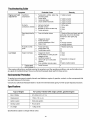
EngineManualfor KawasakiEngine
SAFETYAWARENESS
,_
WARNING:
Whenever you see the symbols shown on the left, heed their instructions!Always follow safe
operating and maintenance practices.
FORWARD
We wish to thank you for purchasing this Kawasaki engine. Please read this Owner's manual carefully before
starting your new engine so that you will be thoroughly familiar with the proper operation of your engine's
control, its features, capabilities and limitations. Also read the manual of the equipment to which this engine
is attached. To ensure a long, trouble-free life for your engine, give it the proper care and maintenance
described in this manual.
Always keep this manual at your fingertip so that you can refer to it whenever you need information. This
manual should be considered a permanent part of the engine and should remain with the engine when it is
sold. All rights reserved. No part of this publication may be reproduced without our prior written permission.
This publication includes the latest information available at the time of printing. However, there may be minor
differences between the actual product and illustrations and text in this manual. All products are subject to
change without prior notice or obligation.
EMISSION CONTROL INFORMATION ..................................................
GENERAL INFORMATION .....................................................................
FUEL AND OIL RECOMMENDATIONS ..................................................
PREPARATION ......................................................................................
Fuel .............................................................................................
Engine Oil ...................................................................................
STARTING ..............................................................................................
Starting Engine ...........................................................................
OPERATING ...........................................................................................
25
27
28
28
27
27
29
29
29
Anti-engine inclination .................................................................
STOPPING ..............................................................................................
Stopping Engine .........................................................................
ADJUSTMENT ........................................................................................
28
29
29
30
Engine Speed Adjustment ..........................................................
MAINTENANCE ......................................................................................
Periodic Maintenance Chart .......................................................
Oil Level Check ...........................................................................
Oil Change ..................................................................................
Air Cleaner Service .....................................................................
30
30
29
29
29
30
Spark Plug Service .....................................................................
STORAGE ...............................................................................................
TROUBLESHOOTING GUIDE ................................................................
ENVIRONMENTAL PROTECTION .........................................................
SPECIFICATIONS ..................................................................................
30
33
34
34
34
24
READTHISFIRST
_lb
WARNING:
Never allow children to operate the engine or equipment.
Keep people and pets out of area where you are using the engine or equipment.
Never wear loose, torn, or bulky clothing. It may catch on moving parts or controls, leading to the risk of
accident.
Never consume alcohol or drug before or while operating this engine.
Do not run the engine in a closed area. Exhaust gas contains carbon monoxide, an odorless and deadly
poison.
Gasoline is extremely flammable and can be explosive under certain condition.
Stop engine and allow the engine to cool before refueling.
Do not smoke. Make sure area is well ventilated and free from any source of flame or sparks including the
pilot light of any appliance while refueling, servicing fuel system, draining gasoline and/or adjusting
carburetor.
Do not fill the tank so the fuel level rises into the filler neck. If the tank is overfilled, heat may cause the fuel
to expand and overflow through the vents in the tank cap.
Wipe off any spilled gasoline immediately.
To prevent fire hazard:
Keep the engine at least 1 m (3.3 ft.) away from buildings, obstructions and other burnable objects.
Do not place flammable objects close to the engine.
Do not expose combustible materials to the engine exhaust.
Do not use the engine on any forest covered, bush covered or grass covered unimproved land unless spark
arrester is installed on the muffler.
To avoid getting an electric shock, do not touch spark plug, plug cap or spark plug lead during engine
running.
To avoid a serious bum, do not touch a hot engine or muffler. The engine becomes hot during operation.
Before you service or remove parts, stop engine and allow the engine to cool.
Do not place hands or feet near moving or rotating parts.
Do not run engine at excessive speeds. This may result in injury.
Always remove the spark plug lead from spark plug when servicing the engine to prevent accidental
starting.
EmissionControlInformation
Board. Also, depending on when your engine was
produced, it may have an assigned emissions durability
pedod. * See below for the engine emissions durability
period that may apply to your engine.
Fuel Information
THIS ENGINE IS CERTIFIED TO OPERATE ON
UNLEADED REGULAR GRADE GASOLINE ONLY.
ExhaustEmissionControlSystem
A minimum of 87 octane of the antiknock index is
The exhaust emission control system applied to this
engine consists of a fuel system and an ignition system
having optimum ignition timing charactedstics. The fuel
system has been calibrated to provide lean air/fuel
mixture characteristics and optimum fuel economy with
a suitable air cleaner and exhaust system
recommended. The antiknock index is posted on
service station pumps in the U.S.A.
To protect the environment in which we all live,
Kawasaki has incorporated an exhaust emission
control system in compliance with applicable
regulations of the United States Environmental
Protection Agency and the California Air Resources
A sealed-type crankcase emission control system is
also used to eliminate blow-by gasses. The blow-by
25
gasses are led to a breather chamber through the
crankcase and from there to the air cleaner.
necessary to ensure compliance with the applicable
standards.
Engine EmissionsCompliancePeriod
California
As the owner of the engine, you have the responsibility
to make sure that the recommended maintenance is
Model Year - 2006 and later Vertical Crankshaft
carried out according to the instructions in this Owner's
Manual at your own expense.
Durability Period - 500 hours
All Other States
The Kawasaki Limited Emission Control System
Warranty requires that you return your engine to an
authorized Kawasaki dealer for remedy under warranty.
Please read the warranty carefully, and keep it valid by
complying with the owner's obligations it contains.
Model Year - 2003 and later (new)
2007 and later (carry over)
Durability Period - 500 hours (Category A}
Tamperingwith EmissionControlSystemProhibited
If your engine has an assigned emissions durability
period it will be located on the certification label
attached to the engine (IMPORTANT ENGINE
INFORMATION).
Federal law and California State law prohibit the
following acts or the causing thereof: (1) the removal or
rendering inoperative by any person other than for
purposes of maintenance, repair, or replacement, of
any device or element of design incorporated into any
new engine for the purposes of emission control prior to
its sale or delivery to the ultimate purchaser or while it is
in use, or (2) the use of the engine after such device or
element of design has been removed or rendered
inoperative by any person.
High AltitudePerformanceAdjustmentInformation
To improve the EMISSIONS CONTROL
PERFORMANCE of engines operated above 1,000
meters (3,300 feet), Kawasaki recommends the
following Environmental Protection Agency (EPA) and
the California Air Resources Board (CARB) approved
modifications.
Among those acts presumed to constitute tampering
are the acts listed below:
NOTE: When properly performed, these specified
modifications only are not considered to be emissions
system
"tampering"
and engine performance
is
generally unchanged as a result.
Do not tamper with the original emission related parts:
Carburetor and internal parts
Spark Plug
Magneto or electronic ignition system
Fuel filter element
Air cleaner elements
Crankcase
InstallationInstructions:
High altitude adjustment requires replacement of
carburetor main jet. Installation of these optional parts
may be performed by an authorized Kawasaki dealer,
or the consumer, following repair recommendations
specified in the appropriate Kawasaki Service Bulletin.
Cylinder head
Breather chamber and internal parts
Intake pipe and tube
Maintenanceand Warranty
Proper maintenance is necessary to ensure that your
engine will continue to have low emission levels. This
Owner's Manual contains those maintenance
recommendations for your engine. Those items
identified by the Periodic Maintenance Chart are
26
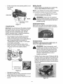
GeneralInformation
Locationof Safety RelatedLabels
Figure 3
A. Fuel Tank Cap
Figure 1
a.
b.
B. Fuel Tank (capacity 2.0L [0.528US gal.])
C. Fuel Tube
Warning
Engine Maintenance
D. Carburetor
E. Priming Pump
F. Air Cleaner
AWARNING
G. Recoil starter
_*FOR rEADOWNER'SMANUAL
SAFE OPERATION
•GASOLINE S FLAMMABLE
KEEPAWAY FROMFLAME
OR SPARKS
_IIk.EXHAUSTGARIS PO SOHOUS
O0
AN NO-RUNENBNE
ENCLOSED
AREA N
;_,TO
,_
RUFFLER
•
UI
I. Oil Drain Plugs (engine oil capacity 0.65L [0.69US
gal.])
AVO O BUR_ DO NOl
rouGHHOT
I_ENQ
H. Recoil Starter Grip
INE
EBO2OO2BZ2
MAINTENANOE
C
71
Figure 4
REFER TO ON_ER'S N_NIIALFOR FURTHER INFO_MAIJOH _
J. Oil Gauge / Filler Cap
K. Spark Plug Cap / Spark Plug
L. Muffler
Engine Serial Number
The engine serial number is your only means of
identifying your particular engine from others of the
same model type.This engine serial number is needed
by your dealer when ordering parts. Refer to Figure 2.
M. P.T.O. Shaft
Tune-upSpecifications
ITEM
Figure 2
27
SPECIFICATION
•
Valve Clearance
•
•
]N 0.12mm(0,005 in,)
EX 0.12mm{0,005 in,}
•
Ignition Timing
•
Unadjustable
•
High Idle Speed
•
3200 r/min (rpm)
•
Spark Plug Gap
•
0.7- 0.8mm(0,028-0,032
•
Other Specifications
•
NO OTHER ADJUSTMENT
NEEDED
in.)
FuelAndOilRecommendations
-2C C
-10°C
O°C
10°C
20°C
30°C 40°C
Fuel
Use only
gasoline.
clean, fresh, unleaded regular grade
OctaneRating
The octane rating of a gasoline is a measure of its
resistance to "knocking".Use a minimum of 87 octane of
the antiknock index is recommended. The antiknock
index is posted on service station pumps in the U.S.A.
Figure 5
NOTE: If "knocking or pinging" occurs, use a different
brand of gasoline orhigher octane rating.
NOTE: Using multi grade oils (5W-20, 10W-30, and
10W-40) will increase oil consumption. Check oil level
more frequently when using them.
CAUTION: Do not mix oil with gasoline
Oxygenated Fuel
Oxygenates (either ethanol or MTBE) are added to the
gasoline. If you use the oxygenated fuel be sure it is
unleaded and meets the minimum octane rating
requirement.The following are the EPA approved
percentages of fuel oxygenates.
ETHANOL: (Ethyl or Grain Alcohol)
You may use gasoline containing up to 10% ethanol by
volume.
MTBE: (Methyl Tertiary Butyl Ether)
Figure 6
You may use gasoline containing up to 15% MTBE by
volume.
Preparation
METHANOL: (Methyl or Wood Alcohol) 5% by volume
Fuel
You may use gasoline containing up to 5% methanol by
volume, as long as it also contains co solvents and
corrosion inhibitors to protect the fuel system.
Level the engine (equipment) before fueling.
Remove the fuel tank cap.
Slowly pour fuel into the fuel tank to bottom (B) of
the filler (A).
Do not overfill the fuel tank, fill only to bottom (B) of the
filler (A) to prevent spill out of the fuel from the tank cap.
Gasoline containing more than 5% methanol by volume
may cause starting and/or performance problems. It
may also damage metal, rubber, and plastic parts of
your fuel system.
dl_
WARNING:
Fuel Tank Capacity, 2.0 L (0.528 us.gal)
Close the tank cap securely by turning it clockwise
as far as it will go.
Gasoline is extremely
flammable and can be explosive under certain
conditions. Do not smoke. Make sure the area
EngineOil
is well ventilated and free from any source of
flame or sparks; this includes any appliance
with a pilot light. Never fill the tank so the fuel
level rises into the filler neck. If the tank is
Check the engine oil level daily before starting the
engine otherwise shortage of the engine oil may cause
serious damage to the engine such as seizure.
Place the engine (equipment) on level surface.
Clean area around the oil gauge before removing it.
Remove the oil gauge (A) and wipe it with clean
cloth.
overfitled, heat may cause the fuel to expand
and overflow through the vents in the tank cap.
Engine Oil
Pour the oil slowly to "FULL" mark on the oil gauge.
Insert the oil gauge into the oil filler (B)WlTHOUT
SCREWING IT IN.
The following engine oils are recommended:
API Service Classification: SF, SG, SH, or SJ.
Oil Viscosity
Remove the oil gauge to check the oil level. Level
should be between "ADD" and "FULL" marks. Do
not overfill.
Choose the viscosity according to the temperature
following chart in Figure 5.
Install and tighten the oil gauge.
Engine Oil Capacity, 0.65 L (0.69 us.qt)
28
CAUTION:The
engine oil.
engine
is shipped
without
DO NOT let the recoil starter grip snap back
itself. This may cause damage to the recoil
starter assembly.
Hold the brake control lever (A) on the equipment
against the handle (B) on the equipment.
Pull the recoil starter grip ((3) slowly until you feel
compression, then pull fast and steady.
Figure 7
Starting
BandPad System
Upon releasing the brake control lever on the
equipment, the cutting blade and the engine will stop
automatically.
Figure 9
A. Brake Control Lever
Therefore, the brake control lever must be held against
the handle while the engine is started and running.
B. Handle
C. Recoil Starter Grip
Starting Engine
Warming up
Fully push the priming button (A) by thumb only
once.
CAUTION: Allow engine to warm up before loading.
This will allow oil to reach all the engine parts, and
the piston clearance to reach design specification,
before the engine is ready for loading.
NOTE: When the engine is already warm or on hot
days, do not push the priming button to prevent faulty
starting engine caused by flooding carburetor.
After engine starts, warm up the engine, run it for a
few minutes.
Operating
Anti-engine inclination
This engine will operate continuously at angles up
to 30°in any direction.
Refer to the operating instructions of the equipment
this engine powers.
Because of equipment design or application, there
may be more stringent restrictions regarding the
angle of operation.
CAUTION: Do not operate this engine continuously
at angles exceeding 30 ° in any direction. Engine
damage could result from insufficient lubrication.
Figure 8
CAUTION:
DO NOT start the engine when the cutting blade
is in contact with long, uncut grass, it may
cause difficulties in starting and damage to the
recoil starter.
DO NOT attempt to start the engine when the
brake control lever on the equipment is
released from your hands; this may cause
damage to the recoil starter or pad system of
the engine.
DO NOT pull the recoil starter grip out of the
end.
Stopping
StoppingEngine
Release the brake control lever (A) on the equipment
from the handle (B) on the equipment to stop the engine
and the cutting blade.
A. Brake Control Lever
29
B. Handle
Adjustment
EngineSpeedAdjustment
NOTE: DO not tamper with the governor setting or the
carburetor setting to increase the engine speed. Each
carburetor is adjusted at the factory with either a cap or
stop plate installed on the mixture screw. Any
adjustments
must be performed
an authorized
Kawasaki dealer.
Figure 10
MAINTENANCE
DAILY
Check oil level and add engine oil
Check for loose or lost nuts and
screws
•
Check for fuel and oi_ leakage
Check for brake control Jever
function
•
Check or clean recoil starter and
air intake screen Tighten nuts
and screws
Clean air cleaner foam element
Clean air cleaner paper element
Change engine oil
Clean and re-gap spark Plug
Replace air cleaner paper
element
Clean dust and dirt from cylinder
and cylinder head fins
Clean combustion chamber
Check and adiust valve clearance
Clean and !ap valve seating I
surface
FIRST 8
HOURS
I
MAINTENANCE
INTERVAL
EVERY 25
HOURS
I
EVERY 50
HOURS
EVERY 100
HOURS
EVERY 200
HOURS
I
I
I
I
I
I
I
I
•
•
•
EVERY 300
HOURS
I
•
•
•
•
•
•
•
I
I
I
I
I
I
I
I
I
I
I
I
I
•
•
I
I
I
I
Periodic Maintenance
I
I
Chart
NOTE: The service intervals indicated are to be used as a guide. Service should be performed more frequently as
necessary by operating condition. Service more frequently under dusty conditions.
Oil LevelCheck
method is recommended.
Check oil level daily and before each operation. Be sure
oil level is maintained. See PREPARATION.
1.Draining0il FromCrank Case
Tip the mower as shown in Figure 11 below.
Remove the dipstick from the engine and pour
entire oil from the crank case into an appropriate
container.
Oil Change
_b
WARNING:
Hot engine oil can cause severe
bums. Allow engine temperature to drop from
hot to warm before draining and handling oil.
,_
WARNING:
Before tipping the equipment,
make sure to run the engine till fuel runs dry.
Change oil after first 8 hours of operation. Thereafter
change oil every 50 hours.
WARNING:
While tipping the engine, keep
muffler side down as shown below.
Run the engine to warm oil.
Be sure the engine (equipment) is level.
Stop the engine.
Two alternate methods of draining oil are described in
the following lines. For convenient handling, the first
3O
Putthemowerbacktoitsoperating
position(onall
fourwheels).
RefillingFreshOil
Remove dipstick and refill with new oil (See FUEL
AND OIL RECOMMENDATIONS chapter).
Dipstick_
NOTE: If you followed the second method of draining
oil, the dipstick is already removed from the engine.
Check the oil level (See PREPARATION chapter),
and secure dipstick to the filler plug.
_lb
WARNING:
Engine oil is toxic substance.
Dispose of used oil properly. Contact your local
authorities for approved disposal methods for
possible recycling.
Tilt mower so engine
tips this way
CoolingSystemCleaning
Figure 11
Before each use, make sure recoil starter (A) is free
from grass and debris to prevent engine overheating.
2. Using0il DrainPlug
IMPORTANT: The oil drain plug on this engine is located
at the bottom and can only be accessed by removing
the baffle and other components. This method of
draining oil involves complicated steps. The first
method, described earlier, is simpler and takes less
time; hence it is the preferred method.
Run the engine for a few minutes and stop the
engine. Tip the mower as shown in Figure 12.
Access the oil drain plug by removing the baffle and
other components following instructions in
"Changing Belts" section on page 14. See Figure
12 for location of the baffle.
Figure 13
Air CleanerService
CAUTION: To prevent excessive engine wear, do
not run the engine with the air cleaner
Remove the oil drain plug from bottom of the
engine. See Figure 12 inset for location of the oil
drain plug. Drain oil into suitable container.
,_
WARNING:
the care
elements
in a wellventilated area Clean
and take
that there
are no
sparks or flame anywhere near the working
area, this includes any appliance with a pilot
light. Do not use gasoline or low flash-point
solvents to clean the element. A fire or
explosion could result.
Unfasten the air cleaner case (C) fastened with the
air cleaner body (D) by sliding the two fasteners (A)
toward the recoil starter (B).Then, with two hands,
pulling the two latches (E) toward you and upward
as shown, separate the air cleaner case from the air
cleaner body.
A.
Oil Drain Plug (on
bottom of engine)
Figure 12
Reinstall the oil drain plug.
Reinstall the baffle and other components removed
earlier. Make sure to secure these now.
Put the mower back on its four wheels and on level
ground.
Figure 14
31
A. Fasteners
A. Slit in the air cleaner body
B. Recoil Starter
B. Projection on the air cleaner case
C. Fasteners
C. Air Cleaner Case
D. Air Cleaner body
E. Latches
CAUTION: After servicing the air cleaner, be sure
all the removed parts are reinstalled properly in
place. Failure to secure fastening of the air cleaner
case with the air cleaner body may cause dirt or
other foreign materials to enter the engine, while it
is running, through the air cleaner, resulting in
engine troubles or failures.
Remove the paper element (A) and the foam element
(B) from the air cleaner body (C).
_
WARNING:
Hot engine components can
cause severe burns. Stop engine and allow it to
cool before checking spark plug.
Clean or replace the spark plug and reset gap (A)
every 100 hours of operation.
Disconnect the spark plug cap from spark plug and
remove the spark plug.
Clean the electrodes (B) by scraping or with a wire
brush to remove carbon deposits.
Inspect for cracked porcelain or other wear and
damage. Replace the spark plug with a new one if
necessary.
Check the spark plug gap and reset it if necessary.
The gap must be between 0.7 and 0.8 mm (0.028
and 0.032").
To change the gap, bend only the side-electrode, using
a spark plug tool.
Figure 15
A. Paper Element
B. Foam Element
C. Air Cleaner body
Foam Element
Clean the foam element every 25 hours.
Wash the element in detergent and water, and dry it
thoroughly.
CAUTION: Do not oil foam element.
Paper Element
-Install and tighten the spark plug to 23 N-m (2.3kgf-m,
17fMb).
Clean the paper element every 100 hours.
Clean the element by tapping gently to remove
dust. If very dirty, replace the element.
Replace paper-element yearly or every 300 hours.
CAUTION: Do not wash paper-element. Do not use
pressurized air to clean or dry paper element.
NOTE: Operating in a dusty condition
more frequent maintenance than above.
-Fit the spark plug cap on the spark plug securely.
-Pull up the spark plug cap lightly to make sure of the
installation of the spark plug cap.
RecommendedSpark Plug
NGK... BPR5ES
may require
Reinstall the foam element and then the paper
element on the air cleaner body.
Reinstall the air cleaner case on the air cleaner
body by first fitting the projection (B) on the edge of
the air cleaner case into the slit (A) in the air cleaner
body. Then, sliding the fasteners (C) toward the air
cleaner case, securely fasten the air cleaner case
with the air cleaner body.
Figure 17
A.
Spark Plug Gap
B.
Electrodes
CAUTION: Be sure to use the same type of spark
plug for change. Resistor spark plug is required in
some areas by local law.
Figure 16
32
Storage
Engine to be stored over 30 days should be completely
drained of fuel (gasoline) to prevent gum deposits
forming on essential carburetor parts and fuel system.
_b
WARNING:
Gasoline is extremely
flammable and can be explosive under certain
conditions. Drain gasoline before storing the
equipment for extended periods. Drain
gasoline in a well-ventilated area away from
any source of flame or sparks, including any
appliances with a pilot light. Store gasoline in
an approved container in safe location.
Figure 18
A. Spark Plug Hole
Slowly pull the recoil starter grip until you feel
compression and leave it there.
Clean every part of the engine.
After period of storage, change engine oil.
(Refer to "Oil Change" section in
"MAINTENANCE" section).
Remove the spark plug cap from spark plug to
prevent accidental starting the engine.
Empty the fuel from the fuel tank with a pump or
siphon.
Fit the plug cap on the spark plug securely
Start and run the engine at idle speed to used up
the fuel in the fuel system.
_bb
WARNING:
Before maintaining engine, stop
the engine and allow it cool.
Remove the spark plug and pour approx. 1-2 mL
(0.06-0.1 cu.in) of new engine oil through the plug
hole (A), slowly pull the recoil starter grip several
times and reinstall the spark plug.
33
Troubleshooting
Guide
Symptom
Engine won't start
output is low
Probable
Insufficient
compression
1.
Cause
2.
3.
4.
Faulty piston, cylinder, piston ring,
and head gasket
Faulty valves
Loose spark plug
Loose cylinder head bolts
1.
2.
3.
4.
No fuel in fuel tank
Blocked rue tube
Blocked air vent in fuel tank cap
Faulty carburetor
1.
Over-rich fuel/air mixture
2.
3.
4.
5.
Clogged air cleaner
Faulty carburetor
Incorrect grade/type of fuel
Water in fuel
No spark or weak
spark
1.
2.
3.
Faulty spark plug
Faulty ignition coil
Faulty engine switch
Engine Overheats
1.
2.
Clogged air cleaner
Recoil Starter or cooling air path
clogged with dirt
Insufficient engine oil
carbon built -up in combustion
chamber
Remedy
1. Tighten properly
2. Tighten properly
3. Tighten properly
4. Tighten properly
No fuel to
combustion chamber
Spark plug fouled by
fuel
Low Output
3.
4.
1.
Engine speed
won't increase
1. Fill fuel tank
2. Clean
3. Clean
4.$
1. Slowly pull the recoil starter grip with
spark plug removed to discharge
excess fuel. clean spark plug
2.Clean
3.$
4. Change Gasoline
5. Change Gasoline
1. Replace spark plug
2.$
3.$
1. Clean
2. Clean
3. Replenish or change oil
4.$
5.
Poor ventilation around engine
5. Select a better location
1.
Faulty Governor
$
If the engine malfunctions,
carefully examine the symptoms and the operating conditions, and use the table above
as a guide to troubleshooting.$
Have an authorized Kawasaki dealer perform these service
Environmental
Protection
To protect our environment, properly discard used batteries, engine oil, gasoline, coolant, or other components that
you might dispose of in the future.
Consult your authorized Kawasaki dealer or local environmental waste agency for their proper disposal procedure.
Specifications
Type of Engine
Air-cooled,
4-stroke
Bore X Stroke
65 x 54mm (2.6 x 2.1 in.)
Displacement
179mL (109. cu.in.)
Ignition system
Solid-state ignition
Starting system
Recoil starter
Dry weight
13.5kg (29.1b)
Specifications subject to change without notice
34
OHV, single cylinder,
gasoline
Engine
Kawasaki
Emission
Limited
Control
Warranty:
Systems:
California
Small
And
Off-Road
Federal
Engines
The California Air Resources Board, the Environmental Protection Agency (EPA), and Kawasaki Motors Corp., U.S.A. (hereinafter "Kawasaki")
are pleased to explain the Emission Control Systems Warranty on your Kawasaki small off-road engine. In California and other states, new small
off-road engines must be designed, built and equipped to meet stringent anti-smog standards. Kawasaki must warrant the emission control system
on your small off-road engine for the period of time listed below provided there has been no abuse, neglect or improper maintenance of your small
off-road engine. Your emission control system may include parts such as the carburetor or fuel-injection system, the ignition system, and catalytic
converter. Also included may be hoses, belts, connectors and other emission related assemblies. Where a warrantable condition exists, Kawasaki
will repair your small off-road engine at no cost to you including diagnosis (if the diagnostic work is Performed at a Kawasaki small off-road engine
dealer), parts and labor.
OWNERS WARRANTY RESPONSIBILITIES.
The following obligations must be fulfilled by the owner to maintain the validity of the Kawasaki
California / EPA Emissions Systems Warranty:
(a)
As the small off-road engine owner, you are responsible for the performance of the required maintenance listed in your owner's manual.
Kawasaki recommends that you retain all receipts covering maintenance on your small off-road engine, but Kawasaki cannot deny warranty
solely for the lack of receipts or for your failure to ensure the performance of all scheduled maintenance.
(b)
You are responsible for presenting your small off-road engine to an authorized Kawasaki small off-road engine Dealer as soon as a problem
exists. The warranty repairs should be completed in a reasonable amount of time, not to exceed 30 days.
(c)
AS the small off-road engine owner, you should also be aware that Kawasaki may deny you warranty coverage if your small off-road engine or
a part has failed due to abuse, neglect, improper maintenance or unapproved modifications.
(d)
If you have any questions regarding your warranty rights and responsibilities, you should contact Kawasaki Motors Corp., U.S.A., Consumer
Services Department, 5080 36th Street, S.E. Grand Rapids, M149512, 616/949-6500.
f.
COVERAGE. Kawasaki warrants to the initial owner and each subsequent purchaser that the small off-road engine is free from defects in
materials and workmanship which cause a failure of a warranted part for a period of two years. Kawasaki is liable for damages to other engine
components caused by the failure of a warranted part still under warranty. The 1995 and later small off-road engines are warranted for two
years in California. In all other states, f 997 and later model year small off-road engines are warranted for two years. If any emission-related
part on your engine is defective, the part will be repaired or replaced by Kawasaki. This warranty time period shall begin on the date the small
off?road engine is delivered to the initial purchaser, or on the date the small off?road engine is first placed in service.
Warranty defects shall be remedied during customary business hours at any authorized Kawasaki small off-road engine dealer located within the
United States of America. Any manufacturer-approved
replacement part may be used in the performance of any warranty maintenance or repairs
on emission-related parts, and must be provided without charge to the owner if the part is still under warranty. Any part or parts replaced under this
warranty shall become the property of Kawasakk
The emission related warranted parts are specifically defined by the California Air Resources Board's Emission Warranty Parts List. (EPA's
regulations do not include a parts list, but EPA considers emission-related parts to include all parts listed here.) These warranted parts are:
carburetor and internal parts, spark advance/retard system, cold start enrichment system, magneto or electronic ignition system, catalytic
converter, intake manifold, exhaust manifold, air cleaner element, and spark plugs if failure occurs prior to the first required scheduled
replacement, hoses, clamps, fittings, gaskets, sealing devices, mounting hardware and tubing used directly in these parts.
Since emission related parts may vary slightly from model to model,certain
contain functionally equivalent parts.
models may not contain all of these parts and certain models may
2.
LIMITATIONS.
(a)
Repair or replacement required as a result of (i) misuse or neglect, (ii) lack of required maintenance. (iii) repairs improperly performed or
replacements improperly installed, (iv) use of replacement parts or accessories not conforming to Kawasaki specifications which adversely
affect performance and/or durability, (v) alterations or modifications not recommended or approved in writing by KawasakL
This Emission Control Systems Warranty shall not cover any of the following:
(b)
Replacement of parts, other services and adjustments
necessary for required maintenance at and after the first scheduled replacement
point.
LIMITED LIABILITY.
(a)
The liability of Kawasaki under this Emission Control Systems Warranty is limited solely to the remedying of defects in materials or
workmanship by any authorized Kawasaki small off-road engine dealer at its place of business during customary business hours. This
warranty does not cover inconvenience or loss of use of the small off-road engine or transportation of the small off-road engine to or from the
Kawasaki Dealer. KAWASAKI SHALL NOT BE LIABLE FOR ANY OTHER EXPENSE, LOSS OR DAMAGE, WHETHER DIRECT,
INCIDENTAL, CONSEQUENTIAL
(EXCEPTION LISTED UNDER COVERAGE) OR EXEMPLARY ARISING IN CONNECTION WITH THE
SALE OR USE OF OR INABILITY TO USE THE KAWASAKI SMALL OFF-ROAD ENGINE FOR ANY PURPOSE.
(b)
NO EXPRESS EMISSION CONTROL SYSTEMS WARRANTY IS GIVEN BY KAWASAKI WITH RESPECT TO THE KAWASAKI SMALL
OFF-ROAD ENGINE EXCEPT AS SPECIFICALLY SET FORTH HEREIN. ANY EMISSION CONTROL SYSTEMS WARRANTY IMPLIED
BY LAW, INCLUDING ANY WARRANTY OF MERCHANTABILITY OR FITNESS FOR A PARTICULAR PURPOSE, IS EXPRESSLY
LIMITED TO THE EMISSION CONTROL SYSTEMS WARRANTY TERMS SET FORTH HEREIN. THE FOREGOING STATEMENTS
WARRANTY ARE EXCLUSIVE
AND IN LIEU OF ALL OTHER REMEDIES.
(c)
(d)
OF
No dealer is authorized to modify this Kawasaki Limited Emission Control Systems Warranty.
Kawasaki is not liable for parts which are not genuine Kawasaki parts except when genuine Kawasaki parts cause damage to non-Kawasaki
parts.
LEGAL RIGHTS: THIS WARRANTY GIVES YOU SPECIFIC LEGAL RIGHTS, AND YOU MAY ALSO HAVE OTHER RIGHTS. THIS WARRANTY
IS IN ADDITION TO THE KAWASAKI LIMITED SMALL OFF-ROAD ENGINE WARRANTY.
35
MANUFACTURER'S
LIMITED WARRANTY
FOR:
®
The limited warranty set forth below is given by Cub Cadet
LLC with respect to new merchandise purchased and used in
the United States, its possessions and territories.
"Cub Cadet" warrants this product against defects in material
and workmanship for a period of two (2) years commencing
on the date of original purchase and will, at its option, repair or
replace, free of charge, any part found to be defective in
materials or workmanship. This limited warranty shall only
apply if this product has been operated and maintained in
accordance with the Operator's Manual furnished with the
product, and has not been subject to misuse, abuse,
commercial use, neglect, accident, improper maintenance,
alteration, vandalism, theft, fire, water, or damage because of
other peril or natural disaster. Damage resulting from the
installation or use of any part, accessory or attachment not
approved by Cub Cadet for use with the product(s) covered
by this manual will void your warranty as to any resulting
damage.
Normal wear parts are warranted to be free from defects in
material and workmanship for a period of thirty (30) days from
the date of purchase. Normal wear parts include, but are not
limited to items such as: batteries, belts, blades, blade
adapters, grass bags, rider deck wheels, seats, snow thrower
skid shoes, shave plates, auger spiral rubber and tires.
HOW TO OBTAIN SERVICE: Warranty service is available,
WITH PROOF OF PURCHASE, through your local authorized
service dealer. To locate the dealer in your area, check your
Yellow Pages, or contact Cub Cadet LLC at P.O. Box 361131,
Cleveland, Ohio 44136-0019, or call 1-877-282-8684, or log
on to our Web site at www.cubcadet.com.
This limited warranty does not provide coverage in the
following cases:
a.
b.
c.
d,
The engine or component parts thereof. These items
may carry a separate manufacturer's warranty. Refer
to applicable manufacturer's warranty for terms and
conditions.
Log splitter pumps, valves, and cylinders have a sepa
rate one year warranty.
Routine maintenance items such as lubricants, filters,
blade sharpening, tune-ups, brake adjustments, clutch
adjustments, deck adjustments, and normal
deterioration of the exterior finish due to use or
exposure.
Cub Cadet does not extend any warranty for products
sold or exported outside of the United States, its
e.
f.
g.
possesions and territories, except those sold through
Cub Cadet's authorized channels of export
distribution.
Replacement parts that are not genuine Cub Cadet
parts.
Service completed by someone other than an
authorized service dealer.
Transportation charges and service calls.
No implied warranty, including any implied warranty of
merchantability of fitness for a particular purpose,
applies after the applicable period of express written
warranty above as to the parts as identified. No other
express warranty, whether written or oral, except as
mentioned above, given by any person or entity,
including a dealer or retailer, with respect to any product,
shall bind Cub Cadet. During the period of the warranty,
the exclusive remedy is repair or replacement of the
product as set forth above.
The provisions as set forth in this warranty provide the
sole and exclusive remedy arising from the sale. Cub
Cadet shall not be liable for incidental or consequential
loss or damage including, without limitation, expenses
incurred for substitute or replacement lawn care services
or for rental expenses to temporarily replace a warranted
product.
Some states do not allow the exclusion or limitation of
incidental or consequential damages, or limitations on how
long an implied warranty lasts, so the above exclusions or
limitations may not apply to you.
In no event shall recovery of any kind be greater than the
amount of the purchase priceofthe product sold. Alteration
of safety features of the product shall void this warranty.
You assume the risk and liability for loss, damage, or injury to
you and your property and/or to others and their property
arising out of the misuse or inability to use the product.
This limited warranty shall not extend to anyone other than the
original purchaser or to the person for whom it was purchased
as a gift.
HOW STATE LAW RELATES TO THIS WARRANTY:
This
limited warranty gives you specific legal rights, and you may
also have other rights which vary from state to state.
IMPORTANT: Owner must present Original Proof of
Purchase to obtain warranty coverage.
CubCadetLLC, P.O. BOX361131CLEVELAND,OHIO44136-0019; Phone:1-877-282-8684