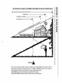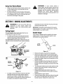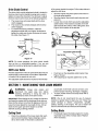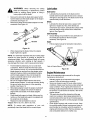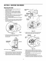
1
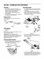
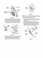
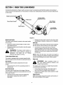
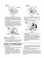
Operator's Manual
21-inch, 6-Speed
Lawn Mower
Model SC 621
IMPORTANT:
Read safety rules and instructions
carefully
before operating
equipment.
Warning: This unit is equipped with an internal combustion engine and should not be used on or near any unimproved forestcovered, brush-covered or grass-covered land unless the engine's exhaust system is equipped with a spark attester meeting
applicable local or state laws (if any). If a spark arrester is used, it should be maintained in effective working order by the operator.
In the State of California the above is required by law (Section 4442 of the California Public Resources Code). Other states may have
similar laws. Federal laws apply on federal lands. A spark arrester for the muffler is available through your nearest engine authorized
service dealer or contact the service department, P.O. Box 368023 Cleveland, Ohio 44136-9722.
CUB CADET CORP.
P.O. BOX 368023 CLEVELAND,
OHIO 44136-9722
ECO # 3520
PRINTED IN U.S.A.
FORM NO. 770-10090B
(11/2000)
TABLEOFCONTENTS
Content
Page
Important Safe Operation Practices ...................................................................
3
Slope Gauge ......................................................................................................
6
Assembling Your Lawn Mower ...........................................................................
7
Know Your Lawn Mower ....................................................................................
9
Operating Your Lawn Mower .............................................................................
10
Making Adjustments ..........................................................................................
12
Maintaining Your Lawn Mower ...........................................................................
13
Service ...............................................................................................................
15
Off-Season Storage ...........................................................................................
16
Troubleshooting
17
.................................................................................................
Parts List ............................................................................................................
18
FINDINGMODELNUMBER
This Operator's Manual is an important part of your new Lawn Mower. It wilt help you assemble, prepare
and maintain the unit for best performance. Please read and understand what it says.
Before you start assembling your new equipment, please locate the model plate on the
equipment and copy the information from it in the space provided below. The information on
the model plate is very important if you need help from our Customer Support Department or
an authorized dealer.
You can locate the model number by standing behind the unit in the operating position and looking
down at the cutting deck. A sample model plate is explained below. For future reference, please copy
the model number and the serial number of the equipment in the space below.
(Model Number)
(Serial Number)
Copy the model number here:
Copy the serial number here:
dl::_fP._"_(
CUB P.O.
CADET
CORP.
BOX 368023
CLEVELAND,
OHIO
44136__
CALLINGCUSTOMER
SUPPORT
If you have difficulty assembling this product or have any questions regarding the controls,
operation or maintenance of this unit, please call the Cub Cadet Customer Dealer Referral Line
at 1-(800)-528-1009. Please have your unit's model number and serial number ready when you
call. See previous section to locate this information. By having the model and serial numbers
ready, you help your Cub Cadet dealer give you faster service.
SECTION1: IMPORTANT
SAFEOPERATION
PRACTICES
WARNING:
This symbol points out important safety instructions which, if not followed, could endanger
the personal safety and/or property of yourself and others. Read and follow all instructions in this manual
before attempting to operate this machine. Failure to comply with these instructions may result in personal
injury. When you see this symbol--HEED ITS WARNING.
WARNING:
Engine exhaust, some of its constituents, and certain vehicle components contain or emit
chemicals known to State of California to cause cancer and birth defects or other reproductive harm.
DANGER: This
any type of power
machine is capable
tions could result in
machine was built to be operated according to the rules for safe operation in this manual. As with
equipment, carelessness or error on the part of the operator can result in serious injury. This
of amputating hands and feet and throwing objects. Failure to observe the following safety instrucserious injury or death.
GeneralOperation
9.
1.
10.
2.
3.
4.
5.
6.
7.
8.
Read this operator's manual carefully in its entirety
before attempting to assemble this machine. Read,
understand, and follow all instructions on the machine
and in the manual(s) before operation. Be completely
familiar with the controls and the proper use of this
machine before operating it. Keep this manual in a safe
place for future and regular reference and for ordering
replacement parts.
This machine is a precision piece of power equipment,
not a plaything. Therefore, exercise extreme caution at all
times. Your unit has been designed to perform one job: to
mow grass. Do not use it for any other purpose.
Never allow children under 14 years old to operate this
machine. Children 14 years old and over should read and
understand the operation instructions and safety rules in
this manual and should be trained and supervised by a
parent. Only responsible individuals who are familiar with
these safe operation rules should use this machine.
Thoroughly inspect the area where the equipment is to
be used. Remove all stones, sticks, wire, bones, toys and
other foreign objects which could be tripped over or
picked up and thrown by the blade. Thrown objects can
cause serious personal injury. Plan your mowing pattern
to avoid discharge of material toward roads, sidewalks,
bystanders and the like. Also, avoid discharging material
against a wall or obstruction which may cause discharged
material to ricochet back toward the operator.
To help avoid blade contact or a thrown object injury, stay
in the operator zone behind the handles and keep
bystanders, helpers, children and pets at least 75 feet
from the machine while it is in operation. Stop machine if
anyone enters the area.
Always wear safety glasses or safety goggles during
operation and while performing an adjustment or repair to
protect your eyes. Thrown objects which ricochet can
cause serious injury to the eyes.
Wear sturdy, rough-soled work shoes and close-fitting
slacks and shirts. Shirts and pants that cover the arms
and legs and steel-toed shoes are recommended. Never
operate this machine in bare feet, sandals, slippery or
light weight (e.g. canvas) shoes.
Do not put hands or feet near rotating parts or under the
cutting deck. Contact with the blade can amputate hands
and feet.
11.
12.
13.
14.
15.
16.
17.
18.
19.
20.
A missing or damaged discharge cover can cause blade
contact or thrown object injuries.
Many injuries occur as a result of the mower being pulled
over the foot during a fall caused by slipping or tripping.
Do not hold on to the mower if you are falling; release the
handle immediately.
Never pull the mower back toward you while you are
walking. If you must back the mower away from a wall or
obstruction first look down and behind to avoid tripping
and then follow these steps:
a. Step back from the mower to fully extend your
arms.
b. Be sure you are well balanced with sure footing.
c. Pull the mower back slowly, no more than half way
toward you.
d. Repeat these steps as needed.
Do not operate the mower while under the influence of
alcohol or drugs.
Do not engage the self-propelled mechanism on units
so equipped while starting engine.
The blade control handle is a safety device. Never
attempt to bypass its operation. Doing so makes the
safety device inoperative and may result in personal
injury through contact with the rotating blade. The blade
control handle must operate easily in both directions and
automatically return to the disengaged position when
released.
Never operate the mower in wet grass. Always be sure of
your footing. A slip and fall can cause serious personal
injury. If you feel you are losing your footing, release the
blade control handle immediately and the blade will stop
rotating within three seconds.
Mow in daylight or good artificial light. Walk, never run.
Stop the blade when crossing gravel ddves, walkways
or roads.
If the equipment should start to vibrate abnormally, stop
the engine and check immediately for the cause.
Vibration is generally a warning of trouble.
Shut the engine off and wait until the blade comes to a
complete stop before removing the grass catcher or
unclogging the chute. The cutting blade continues to
rotate for a few seconds after the engine is shut off.
Never place any part of the body in the blade area until
you are sure the blade has stopped rotating.
Never operate mower without proper trail shield,
discharge cover, grass catcher, blade control handle or
othersafety
protective
devices
inplaceandworking.
power mower. Children 14 years old and over should
Never
operate
mower
withdamaged
safetydevices.
read and understand the operation instructions and
Failure
todoso,canresultinpersonal
injury.
safety rules in this manual and should be trained and
21. Mufflerandenginebecomehotandcancauseabum.
Do
supervised by a parent.
nottouch.
22. Onlyusepartsandaccessories
made
forthismachine
by Service
theodginal
equipment
manufacturer
(O.E.M).
Failure
to
dosocanresultinpersonal
injury.
Safe Handlingof Gasoline:
23. Ifsituations
occurwhich
arenotcovered
inthismanual, 1. To avoid personal injury or property damage use extreme
usecareandgoodjudgment.
Contact
yourdealer
for
care in handling gasoline. Gasoline is extremely
assistance.
Telephone
1-800-528-1009
forthenameof
flammable and the vapors are explosive. Serious
yournearest
dealer.
personal injury can occur when gasoline is spilled on
SlopeOperation
Slopes are a major factor related to slip and fall accidents
which can result in severe injury. Operation on slopes
requires extra caution. If you feel uneasy on a slope, do not
mow it. Before operating this unit on a slope or hilly area, use
the slope gauge on page 6 to measure slopes. If the slope is
greater than 15 degrees, do not mow it.
Do:
1.
2.
3.
Mow across the face of slopes; never up and down.
Exercise extreme caution when changing direction on
slopes.
Watch for holes, ruts, rocks, hidden objects, or bumps
which can cause you to slip or trip. Tall grass can hide
obstacles.
Always be sure of your footing. A slip and fall can cause
serious personal injury. If you feel you are losing your
balance, release the blade control handle immediately,
and the blade will stop rotating within 3 seconds.
Do Not:
1.
2.
3.
Do not mow near drop-offs, ditches or embankments,
you could lose your footing or balance.
Do not mow slopes greater than 15 degrees as shown on
the slope gauge.
Do not mow on wet grass. Unstable footing could cause
slipping.
yourself or your clothes which can ignite.
Wash your skin and change clothes immediately.
Use only an approved gasoline container.
Never fill containers inside a vehicle or on a truck or
trailer bed with a plastic liner. Always place containers on
the ground away from your vehicle before filling.
5. If possible, remove gas-powered equipment from the
truck or trailer and refuel it on the ground. If this is not
possible, then refuel such equipment on a trailer with a
portable container, rather than from a gasoline dispenser
nozzle.
6. Keep the nozzle in contact with the rim of the fuel tank or
container opening at all times until fueling is complete. Do
not use a nozzle lock-open device.
7. Extinguish all cigarettes, cigars, pipes and other sources
of ignition.
8. Never fuel machine indoors because flammable vapors
will accumulate in the area.
9. Never remove gas cap or add fuel while the engine is hot
or running. Allow engine to cool at least two minutes
before refueling.
10. Never over fill fuel tank. Fill tank to no more than V_inch
2.
3.
4.
below bottom of filler neck to provide space for fuel
expansion.
11. Replace gasoline cap and tighten securely.
12. If gasoline is spilled, wipe it off the engine and
equipment. Move unit to another area. Wait 5 minutes
before starting the engine.
13. Never store the machine or fuel container inside where
Tragic accidents can occur if the operator is not alert to the
presence of children. Children are often attracted to the
mower and the mowing activity. They do not understand the
dangers. Never assume that children will remain where you
last saw them.
there is an open flame, spark or pilot light as on a water
heater, space heater, furnace, clothes dryer or other gas
appliances.
14. To reduce fire hazard, keep mower free of grass, leaves,
or other debris build-up. Clean up oil or fuel spillage and
remove any fuel soaked debris.
15. Allow a mower to cool at least 5 minutes before stodng.
1.
GeneralService:
Children
2.
3.
4.
5.
6.
Keep children out of the mowing area and under the
watchful care of a responsible adult other than the
operator.
Be alert and turn mower off if a child enters the area.
Before and while moving backwards, look behind and
down for small children.
Use extreme care when approaching blind corners,
doorways, shrubs, trees, or other objects that may
obscure your vision of a child who may run into the
mower.
Keep children away from hot or running engines. They
can suffer burns from a hot muffler.
Never allow children under 14 years old to operate a
1.
2.
3.
Never run an engine indoors or in a poorly ventilated
area. Engine exhaust contains carbon monoxide, an
odorless and deadly gas.
Before cleaning, repairing, or inspecting, make certain
the blade and all moving parts have stopped. Disconnect
the spark plug wire and ground against the engine to
prevent unintended starting.
Check the blade and engine mounting bolts at frequent
intervals for proper tightness. Also, visually inspect blade
for damage (e.g., bent, cracked, worn) Replace blade
with the original equipment manufacture's (O.E.M.) blade
only, listed in this manual. "Use of parts which do not
meettheoriginal
equipment
specifications
mayleadto
improper
performance
andcompromise
safety!"
4. Mowerblades
aresharpandcancut.Wrapthebladeor
weargloves,
anduseextra caution when servicing them.
5.
6.
7.
8.
9.
Keep all nuts, bolts, and screws tight to be sure the
equipment is in safe working condition.
Never tamper with safety devices. Check their proper
operation regularly.
After striking a foreign object, stop the engine, disconnect
the spark plug wire and ground against the engine.
Thoroughly inspect the mower for any damage. Repair
the damage before starting and operating the mower.
Never attempt to make a wheel or cutting height
adjustment while the engine is running.
Grass catcher components, discharge cover, and trail
shield are subject to wear and damage which could
expose moving parts or allow objects to be thrown. For
safety protection, frequently check components and
replace immediately with original equipment
manufacturer's (O.E.M.) parts only, listed in this manual.
"Use of parts which do not meet the original equipment
specifications may lead to improper performance and
compromise safety!"
10. Do not change the engine governor setting or overspeed
the engine. The governor controls the maximum safe
operating speed of the engine.
11. Maintain or replace safety and instruction labels, as
necessary.
12. Observe proper disposal laws and regulations. Improper
disposal of fluids and materials can harm the
environment.
YourResponsibility
•
Restrict the use of this power machine to persons who read, understand
this manual and on the machine.
and follow the warnings and instructions
WARNING
in
USE THIS PAGE AS A GUIDE
TO DETERMINE
SLOPES
WHERE
YOU MAY NOT OPERATE
SAFELY.
¢#
SIGHT AND HOLD THIS LEVEL WITH A VERTICAL TREE
A POWER POLE
A CORNER
OF A BUILDING
OR A FENCE POST
5"
I
I
O)
¢#
o)
¢0
t
I
O3
,.<
O
C
3
¢0
o
O
¢0
8.
¢#
3
o)
¢0
WARNING
,_
.'F
Do not mow on inclines with a slope in excess of 15 degrees (a rise of approximately 2-1/2 feet every 10 feet). A
riding mower could overturn and cause serious injury. If operating a walk-behind mower on such a slope, it is
extremely difficult to maintain your footing and you could slip, resulting in serious injury.
Operate RIDING mowers up and down slopes, never across the face of slopes.
Operate WALK-BEHIND mowers across the face of slopes, never up and down slopes.
m
SECTION3: ASSEMBLING
YOURLAWNMOWER
Unpacking
AssemblingHandle
•
•
•
•
•
Remove staples, break glue on top flaps, or cut
tape at carton end and peel along top flap to open.
Remove loose parts if included with unit (i.e.,
operator's manual, hardware pack etc.).
Cut corners and lay carton down flat. Remove
packing material.
Roll or slide unit out of carton. Check for loose parts
thoroughly before discarding carton.
•
•
For shipping purposes, the grass bag was packed
on top of the unit. Remove the grass bag and set it
out of the way.
Pull the upper handle upwards in the direction
shown in Figure 3. Align it with the lower handle.
Tighten wing nut securing the upper handle with the
lower handle on each side.
Upper
Handle
HardwarePack
Please identify each piece of the hardware pack as
shown in Figure 1.
_Wing
Nut
1/4-20 (2)
e Bolt
1/4-20 (2)
Lower
Handle
Figure 1
ToolsRequired
1.
2.
Pair of Pliers
Funnel
Bolt
NOTE: Reference to right or left hand side of the mower
is from the operating position.
IMPORTANT: This unit is shipped WITHOUT
GASOLINE OR OIL in the engine. Be certain to service
engine with fresh gasoline and oil as instructed in the
engine manual, the engine manual is packed
seperatety in the carton.
Nut
Figure 3
Raise complete handle assembly, as shown in
Figure 4, until it clicks into place. Make sure not to
kink the control cables.
Handle
Assembly
Disconnect
SparkPlugWire
•
Disconnect the spark plug wire from the spark plug,
and ground it against the engine by attaching
rubber boot to a bolt. See Figure 2.
Spark
Wire
Spark Plug
Figure 4
Figure 2
Pinch lower handle against the handle mounting
bracket with a pair of pliers. Move hairpin clip from the
outer to the inner hole of the weld pin on the handle
mounting bracket on each side. See Figure 5.
Cable Tie
\
Lowe
Handle
Lowe_
Handl
pin
Clip
Handle Mountin
Bracket
Figure 7
Figure 5
After you have moved the hairpin clips, place one
carriage bolt (included in the hardware pack) in the
upper hole of the right handle mounting bracket
from the inside outward. See Figure 6. Secure with
one plastic wing nut. Repeat process on the left.
NOTE: Make sure the drive cable is routed around the
outside and above the lower handle so as not to
interfere with the grass bag attachment.
The rope guide, which is connected to the support
rod, is located on the right side of the lower handle.
See Figure 8.
With the spark plug wire disconnected and
grounded, hold the blade control handle against the
upper handle, and pull the starter rope out of the
engine. Release the blade control handle. Slip the
starter rope into the rope guide. See Figure 8.
Starter
Rope
_Support
Rod
Guide
Figure 6
Attach control cables to handle by inserting post of
cable ties into the holes on the lower handle. The
holes may be on either side of the handle. Pull
cable ties tight and cut off the extra. See Figure 7.
Figure 8
SECTION4: KNOWYOURLAWNMOWER
Compare the illustrations in Figure 9 with your lawn mower to acquaint yourself with the location and working of
various controls and adjustments on the equipment. Always wear safety glasses while performing any adjustments
on the mower.
Blade Control
Cuffing Height
_stment Lever
Front Wheel
Drive Clutch Control
Front Wheel
Height Adjuster
Figure 9
Blade ControlHandle
•
The blade control handle is located on the upper handle
of the mower.
•
•
Depress the blade control handle in order to start
and operate the unit.
Release the blade control handle to stop the engine
and the blade.
WARNING:
negotiating an obstacle, making a turn or stopping.
Shift Lever
The shift lever is the shorter of the two levers located in
the drive clutch control housing on the upper handle.
•
The blade control handle is a
safety device. Never attempt to bypass its
operations.
The blade will be rotating
whenever the engine is running.
Release the drive clutch control to stow down when
Use this lever to select any of the six forward
speeds available on this mower model. Note that
when sliding the lever up or down to change speed
selection, you will have to release the drive clutch
control lever.
Throttle Control/ChokeLever
NOTE: Move the shift lever only when the engine is
running. Changing the shift lever setting with the engine
off can cause damage to the mower's drive system.
The engine is equipped with a constant speed throttle,
which is already set at full throttle for best performance.
CasterLock
Recoil Starter
hills,
front wheels
should
be locked
in the
WARNING:
When
operating
mower
on
straight ahead position.
The recoil starter handle is attached to the lower
handle.
_,
•
The casters can be locked in a straight ahead position
or can be left to swivel freely.
Stand behind the unit in the operating position to
start the unit.
Drive ClutchControl
•
The drive clutch control lever is the longer of the two
levers located in a seperate housing attached to the top
of the upper handle.
•
•
EngineControls
Squeeze the drive clutch control to engage the
drive system; release the clutch control to
disengage.
Lift and place the lock pins in the larger holes to
lock the wheels for straight-ahead operation.
Place pins in smaller holes to allow casters to rotate
freely for turning.
Refer to the engine manual for location and function of
the controls located on the engine.
SECTION5: OPERATING
YOURLAWNMOWER
rewind slowly. Pull rope with a rapid, continuous,
full arm stroke. Keeping a firm grip on the starter
handle, let the rope rewind slowly.
GasandOilFill-Up
•
Service the engine with gasoline and oil as
instructed in the accompanying engine manual.
Follow all instructions carefully.
WARNING:
StoppingEngineandBlade
Never fill fuel tank indoors,
•
with engine running or until the engine has
been allowed to cool for at least two minutes
Release the blade control handle to stop the engine
and blade.
after running.
for
a few seconds
the continues
engine is shut
off.
WARNING:
Theafter
blade
to rotate
,_
BeforeStarting
•
•
NeutralAdjustmentTest
Attach spark plug wire to spark plug. Make certain
the metal cap on the end of the spark plug wire
(inside the rubber boot) is fastened securely over
the metal tip on the spark plug.
Check the drive clutch control for proper
adjustment. If the mower does not propel itself or
the drive wheels hesitate with the drive clutch
•
To perform this test, answer the following questions
after having started the mower and engaged the
drive clutch control:
1.
engaged, perform the drive clutch control
adjustment as instructed on page 16.
2.
3.
StartingEngine
•
4_11
operator is standing
the other
lawn than
mower
WARNING:
Be sure near
no one
the
while starting engine or operating mower.
Never run engine indoors or in enclosed,
poorly ventilated
areas. Engine exhaust
contains carbon monoxide, an odorless and
deadly gas.
IMPORTANT: If you are cutting grass on a slope, always
lock the front wheel casters of your mower for straight
ahead operation. On level ground you may leave the
casters unlocked to pivot freely.
When starting the unit for the first time, face
the mower against a solid object such as a
wall, fence, etc. Start the unit and if it shows
any signs of motion while the drive clutch
control is still disengaged, shut the engine off
immediately.
•
•
•
sharp bends?
If you answered "yes' to all three questions, your
mower passed the test and you can start your
mower. If you answered "no" to any of the three
questions, you need to perform the "Drive Clutch
Control Adjustment" as instructed on page 13.
LockingCasters
Keep hands, feet, hair and loose clothing
away from any moving parts on engine and
lawn mower.
•
With the engine OFF and the drive clutch
control released, push mower forward and pull
it backward. Does it move freely?
Squeeze drive clutch control and pull the
mower backward. Do rear wheels lock up?
Is the drive clutch control cable free of kinks or
Unlocked
Position
Locked
Make sure that the drive clutch control is adjusted
so the drive belt is as loose as possible.
Push the primer three times. Wait two seconds
between each push. In temperatures below 55 ° F,
prime five times. Do not prime to restart a warm
engine after a short shutdown.
Standing behind the mower, depress the blade
control handle and hold it against the upper handle.
Grasp starter handle and pull rope out slowly until
engine reaches start of compression cycle (rope
will pull slightly harder at this point). Let the rope
Figure 10
•
•
10
To turn the mower on a slope with casters locked,
depress the upper handle and raise the front
wheels slightly.
To lock caster: Lift and place the lock pin in the
larger hole on each caster. See Figure 10.
•
To unlock caster: Lift and place the lock pin in the
smaller hole to allow casters to rotate freely. See
Figure 10.
Chute
Door
Lift bag
here
Lower Handle of /
Grass Bag
/
casters unlocked since the mower can drift
WARNING:
Do not mow on slopes with
downhill.
BaggingGrassClippings
This mower can bag grass clippings. For that, you will
have to install the grass bag on to the unit.
•
Remove the three wing nuts holding the mulching
baffle or side discharge chute in place. Then
remove the plug or the chute as the case may be.
See Figure 11.
Figure 13
EmptyingYour GrassBag
•
Lift grass bag from the bagging adapter using the
lower handle of the grass bag. While holding the
lower handle, lift up the rear section of the grass
bag. See Figure 13. The bag will open and grass
clippings will fall out. Empty the grass bag at a
proper disposal site.
Nut
Remove
mulching baffle
J
Side-Discharge
GrassClippings
•_ -_---_
Wing Nut
This mower can also side-discharge grass clippings.
For that, you will have to install the side-discharge
chute on to the unit.
Figure 11
Replace with bagging adapter. Attach using three
wing nuts removed earlier. Be sure that inner lip of
attachment goes under the edge of the deck. See
Figure 12.
•
•
Bagging
Adapte_
\
Remove mulching baffle or grass bag adapter. See
Figure 11.
Attach discharge chute with wing nuts. See Figure
14. Once the side-discharge chute is in place, you
can run the mower and the grass clippings will be
discharged sideways.
<_=
Side-Discharge
Chute
Figure 14
Figure 12
MulchingGrass
Lift chute door and slide bag onto adapter. Top of
bag rests on wire bracket that extends between the
handles. See Figure 13.
•
11
When the mulching baffle is installed on the unit,
the mower is used to mulch grass clippings. If the
mulching baffle is not already installed, you will
have to remove the grass bag or side-discharge
chute as the case may be, and install the mulching
baffle for the purpose. Make sure wing nuts
securing the mulching baffle to the deck (Figure 11 )
are firmly tightened before starting to mulch.
UsingYourRotaryMower
•
WARNING:
If your mower strikes a
foreign object, stop the engine. Remove wire
from spark plug, thoroughly inspect for any
damage, and do necessary repairs before
operating the mower again. Extensive
vibration of the mower during operation is an
indication of damage.
Make sure that lawn is clear of stones, sticks, wire,
or other objects which could damage the lawn
mower or its engine..
For best results, do not cut wet grass. New grass,
thick grass or wet grass may require a narrower cut.
For a healthier lawn, never cut off more than onethird of the total length of the grass.
•
•
SECTION6: MAKINGADJUSTMENTS
assembly and secure with the wing nut previously
removed. See Figure 15B.
WARNING:
Do not at any time make any
adjustment to lawn mower without first
stopping engine and disconnecting
spark
plug wire.
IMPORTANT: All wheels must be placed in the same
relative position. For rough or uneven lawns, raise the
cutting height of your lawn mower.
CuttingHeight
HandleHeight
The rear wheel cutting height adjustment lever is
located above the left rear wheel.
•
Your mower is shipped with the handle in the higher
height position.To lower the handle height for your
convenience, proceed as follows.
To adjust, pull the lever out and away from the
mower and move it forward or backward to the
desired cutting height. See Figure 15A.
The front wheel cutting height is determined by the
selection of one of six slots in each caster assembly.
[]
Handle
Adjustment
Lever
Figure 16
•
•
[]
•
•
Axle Bolt \
_$J_.'_\
_
Notch
Nut
•
•
Figure 15
To adjust, remove the wing nut from the axle bolt.
Slide the axle bolt and spring washer from the
assembly and select a cutting height. With the
spring washer on the axle bolt, reinsert hardware in
the square hole desired through the wheel
•
•
12
Remove the starter rope from the rope guide.
Remove the upper handle by removing the hand
knobs and carriage bolts. Lay the upper handle out
of the way, being careful not to bend or kink cables.
Remove the hairpin clips from the weld pins on the
handle brackets.
Remove carriage bolts and wing nuts from the two
handle brackets on both sides. Press outward on
the legs of the lower handle, and remove it from the
mower.
Turn the lower handle around so the notches on the
bottom of the lower handle are facing forward as
shown in Figure 16.
Reassemble, placing the bottom holes in the
handle over the weld pins in the handle mounting
bracket.
Reassemble the upper handle.
Place the hairpin clips in the inner holes in the weld
pins. Secure carriage bolts and wing nuts on the
handle brackets. Reattach the starter rope.
DriveClutchControl
of the mower beside the engine. Follow steps below to
adjust the shift lever.
The drive clutch control adjustment wheel is located in
the drive clutch control handle housing and is used to
tighten or loosen the drive belt. You will have to adjust
the drive clutch control if any of the following happens:
1.
2.
•
•
•
The mower does not propel itself with the drive
clutch engaged.
The mower's drive wheels hesitate with the drive
•
clutch engaged.
To resolve the above problems, rotate the
adjustment wheel with your fingers: clockwise to
tighten the cable and counter-clockwise to loosen
the cable. See Figure 17.
Start the engine and place speed control lever in
the sixth speed position.
Stop the engine; disconnect spark plug wire and
ground it.
Loosen hex nut (A) which secures the adjustable
cable bracket. This bracket is located on the left
side (towards the center) of the cutting deck. See
Figure 18 for location of the bracket.
Bottom View
Adjust_en
_
Wheel
\\
_
___
Hex Nut Adj,
Figure 17
NOTE: For some operators, the drive clutch handle
may not be in a comfortable position. If so, you can
adjust the handle by tightening the adjustment wheel
ShiftLeverCable
Figure 18
Periodic adjustment of the six-speed shift cable may be
required due to normal wear on the cable. Adjustment
is needed if all six speeds do not work.
•
•
Push back on the adjustable cable bracket. See
Figure 18 inset.
After adjusting as required, tighten hex nut (A).
The adjustable cable bracket is located on the left side
SECTION7: MAINTAININGYOURLAWNMOWER
accumulate, it wilt invite rust and corrosion, and
prevent proper mulching, discharge or bagging.
To clean, tilt the mower and scrape clean with a
suitable tool.
disconnect
spark stop
plug wire
WARNING: the Always
engine before
and
cleaning, lubricating or doing any kind of
maintenance work on the lawn mower.
NOTE: We do not recommend the use of pressure
washers or garden hose to clean your unit. These may
cause damage to electric components, spindles,
pulleys, bearing or the engine. The use of water will
result in shortened life and reduced serviceability.
IMPORTANT: When tipping the unit, empty the fuel tank
and keep the engine with the discharge chute side up.
Never tip the mower more than 90 degrees and do not
leave the mower tipped for any length of time. Oil can
drain into the upper part of the engine or air filter
element causing a starting problem.
CuttingBlade
CuttingDeck
•
•
Clean the underside of the mower deck after each
use to prevent buildup of grass clippings, leaves,
dirt or other matter. If this debris is allowed to
13
Periodically inspect the blade adapter for cracks,
especially if you strike a foreign object. Replace
when necessary.
Lubrication
WARNING:
When removing the cutting
blade for sharpening or replacement, protect
hands by wearing heavy gloves or using a
heavy rag to hold the blade.
•
•
BladeControl
•
Remove the bolt and the blade bell support which
hold the blade and the blade adapter to the engine
crankshaft. See Figure 19
Remove the blade and the blade adapter from the
crankshaft. See Figure 19.
Lubricate the pivot points on the blade control
handle and the brake cable at least once a season
with light oil. See Figure 20. The blade control must
operate freely in both directions.
Wheels
•
Lubricate the wheel at least once a season with
light oil (or engine oil). Also, if the wheels are
removed for any reason, lubricate the surface of the
axle bolt and the inner surface of the wheel with
light oil. See Figure 20.
Blade
Adapter
CasterAssembly
/
•
Blade Bell
Support
Hex Bolt
Engine
•
Figure 19
•
Grease fittings are provided for easy lubrication of
the swivel pins located on the front caster
assembly. See Figure 20.
Follow engine manual for lubrication instructions.
Lubricate
Lubricate
Lubricate
When sharpening the blade, follow the original
angle of grind as a guide.
Lubricate
NOTE: It is extremely important that each cuffing edge
receives an equal amount of grinding to prevent an
unbalanced blade. Such unbalanced blade will cause
excessive vibration when rotating at high speeds. It
may damage the mower, and/or cause personal injury.
•
•
•
•
•
Test the blade by balancing it on a round shaft
screwdriver. Remove metal from the heavy side
until it balances evenly. It is recommended that the
blade always be removed from the adapter when
testing for balance. Before reinstalling the blade
and the blade adapter to the unit, lubricate the
engine crankshaft and the inner surface of the
blade adapter with light oil.
Be sure to install the blade with the side of the
Refer to Engine Manual
Figure 20
EngineMaintenance
Refer to the separate engine manual for all engine
maintenance instructions.
•
blade marked "Bottom" (or with part number) facing
the ground when the mower is in the operating
position. See Figure 19.
Slide blade adapter toward the engine crankshaft
Place blade on adapter. Be certain the blade is
aligned with and seated on the blade adapter
flanges.
Place blade bell support on blade. Make sure the
notches on the blade bell support are aligned with
the small hole in the blade.
•
•
•
Replace hex bolt and tighten to secure.
Torque: 450 in. Ibs. min., 600 in. lbs. max.
•
NOTE: To ensure safe operations of your unit,
periodically check the blade bolt for correct torque.
14
Maintain engine oil as instructed in the engine
manual. Follow all instructions carefully.
Service air cleaner every 25 hours under normal
conditions. Clean every few hours under extremely
dusty conditions. Poor engine performance and
flooding usually indicates that the air cleaner should
be serviced. To service the air cleaner, refer to the
engine manual.
The spark plug should be cleaned and the gap
reset once a season. Spark plug replacement is
recommended at the start of each mowing season.
Check engine manual for correct plug type and gap
specifications.
Clean engine regularly with a cloth or brush. Keep
the cooling system (blower housing area) clean to
permit proper air circulation which is essential to
engine performance and life. Remove all grass, dirt
and combustible debris from muffler area.
SECTION8: SERVICING
YOURMOWER
ReplacingDriveBelt
•
•
•
•
•
•
Disconnect the spark plug wire and ground it
against the engine.
Drain the fuel tank or place a piece of plastic
beneath the cap to prevent gasoline leakage.
Place shift lever in the first position and tip the
mower on its side.
Remove the center bolt which secures the blade to
Transmission __
Pulley
Belt_
Belt Keepe
Bracket-Idler Pulley --''''_
Bracket
Idler_
Pulle_
the crankshaft followed by blade bell support,
blade, and blade adapter.
Move the cutting height adjustment to the highest
position.
Remove the three hex screws holding the baffle to
the deck and pivot baffle towards the rear of the
mower. See Figure 21.
Transmission
Bolt and/
Locknut
Figure 23
Baffle
Slide the belt out from between the belt keeper
bracket and the idler pulley. See Figure 23.
Figure 21
Remove the hex bolt from the rear of unit holding
the transmission to the mower housing.
See Figure 22.
Six-Speed
Cable Slot
Belt
Control
Arm
Cutting Height
Adjustment
Figure 24
NOTE: Mower is flipped on itsleft wheels for better access.
•
Figure 22
•
Tilt the transmission forward and loosen the idler
•
pulley bolt and lock nut half a turn. See Figure 23.
Using a pair of pliers, pull back and rotate belt
keeper bracket from the slot on the idler pulley.
•
•
15
Squeeze the belt together and push it forward,
while pressing the control arm inward towards the
deck. Remove the six-speed cable from the slot.
See Figure 24.
Pivot the control arm down and away from the
pulley and the belt. See Figure 24.
Lift off the lower pulley assembly and remove the
old belt from around the crankshaft. See Figure 25.
Lower
Pulley F
o
Lower Pulley
Half'x /
"_
_
o
o o
Belt
,_
Figure 27
Figure 25
•
•
•
•
•
•
Place the new belt over the transmission pulley.
Start the belt in the pulley groove and rotate the
pulley until the belt is seated in transmission pulley.
Place the belt between the idler pulley and the belt
keeper bracket.
Using a pair of pliers, rotate the belt keeper bracket
so that it snaps into slot on the idler bracket.
Tighten the idler pulley bolt and lock nut half a turn.
Place the belt between the two pulley halves on the
crankshaft. Make sure to route the belt inside the
belt guard pin. See Figure 26.
o
Belt
ard Pin
•
Pivot the control arm back to its original position
and reinstall the six-speed cable into the slot. See
Figure 28.
Check and make sure the belt is routed inside the
pulley halves and the belt guard pin.
Six-Speed
Cable Slot
o
Control _
Arm
Figure 28
Reinstall the bolt securing transmission to rear
mower housing.
Pivot the baffle back to its original position and
secure with three hex screws earlier removed.
Lightly lubricate the inside of the blade adapter and
reinstall the spacer, wave washer, blade adapter
assembly, and blade in the correct order.
Tighten the hex bolt to secure the blade to torque:
450-600 in. Ibs.
Pulley
Half
Figure 26
IMPORTANT: When replacing the belt, do not disassemble the lower pulley assembly.
•
Pinch both sides of the belt together so that the belt
is not in the pulley groove, and the lower pulley can
be pushed towards the engine. See Figure 27.
SECTION9: OFF-SEASON
STORAGE
The following steps should be taken to prepare lawn
mower for storage.
•
•
•
•
Clean and lubricate mower thoroughly as described
in the lubrication instructions.
We do not recommend the use of pressure
washers or garden hose to clean your unit. They
may cause damage to electric components,
spindles, pulleys, bearings or the engine. The use
of water will result in shortened life and reduce
serviceability.
•
Refer to engine manual for storage instructions.
Coat mower's cutting blade with chassis grease to
prevent rusting.
Store mower in a dry, clean area. Do not store next
to corrosive materials, such as fertilizer.
NOTE: When storing any type of power equipment
an unventilated or metal storage shed, care should
taken to rust-proof the equipment. Using a light oil
silicone, coat the equipment, especially cables and
moving parts.
16
in
be
or
all
SECTION10: TROUBLE
SHOOTING
GUIDE
Trouble
Possible Cause(s)
1. Blade control handle
disengaged.
2. Spark plug wire disconnected.
3. Engine not primed.
4. Fuel tank empty, or stale fuel.
5. Blocked fuel line.
6. Faulty spark plug.
7. Engine flooded.
1. Spark plug wire loose.
2. Blocked fuel line or stale fuel.
Corrective Action
3.
4.
5.
6.
Vent in gas cap plugged.
Water or dirt in fuel system.
Dirty air cleaner.
Carburetor out of adjustment.
3.
4.
5.
6.
Engine overheats
1.
2.
3.
1.
2.
3.
Occasional skip (hesitates)
at high speed
Idles poorly
1.
Engine oil level low.
Air flow restricted.
Carburetor not adjusted
properly.
Spark plug gap too close.
Engage blade control handle.
Connect wire to spark plug.
Depress primer bulb slowly three
times.
Fill tank with clean, fresh gasoline.
Clean fuel line.
Clean, adjust gap or replace.
Wait for the engine to dry out.
Tighten spark plug wire.
Clean fuel line; fill tank with fresh
gasoline.
Clear vent.
Drain fuel tank. Refill with fresh fuel.
Clean air cleaner.
Adjust carburetor. Follow engine
manual.
Fill crankcase with proper oil.
Remove blower housing and clean.
Adjust carburetor.
1.
Adjust gap to .030".
Spark plug fouled, faulty or
gap too wide.
Carburetor out of adjustment.
1.
Reset gap to .030" or replace spark
plug.
Adjust carburetor. Follow engine
manual.
Clean air cleaner.
Tighten blade and adapter. Balance
blade.
Replace blade.
Wait until later to cut.
Mow once at a high cutting height,
then mow again at desired height or
make a narrower cutting swath (1/2
width).
Sharpen or replace blade.
Placeallfourwheetsinsame
height
position.
Sharpen or replace blade.
Engine fails to start
Engine runs erratic
1.
2.
Excessive vibration
3.
1.
2.
Mower wilt not mulch grass 1.
2.
Uneven cut
3.
1.
2.
1.
2.
3.
4.
5.
6.
7.
1.
2.
2.
Dirty air cleaner.
Cutting blade loose or
unbalanced,
Bent cutting blade.
Wet grass.
Excessively high grass.
3.
1.
Dull blade.
Wheels not positioned
correctly,
Dull blade.
3.
1.
2.
1.
2.
2.
Refer to separate engine manual packed with your mower for more engine related information.
NOTE: For repairs beyond the minor adjustments listed above, contact your nearest Cub Cadet dealer.
17
SECTION11: PARTSLISTFORMODELSC621
Transmission Assembly
64
J
14
/
38
"_30 33
15
26
7
Pulley Assembly
Reference only
•75
6O
51
\
58
55
59
56
\
39
16
37
25
61
48
87
86
g
84
8
lO
83
/_
70
68
18
NOTE: For painted parts, please refer to
the list of color codes below. Please add
the applicable
color code
wherever
needed, to the pan number to order a
replacement part. For instance if a part
numbered 70O-xxxx is painted Cub Yellow.
the part number to order would be 70Oxxxx-0716.
Cub Yellow: 0716
Powder Black: 0637
ModelSC621
Ref.
No.
I
2
3
4
5
6
7
8
9
10
11
12
13
14
15
16
17
18
19
20
21
22
23
24
25
26
27
28
29
30
31
32
33
34
35
36
37
38
39
40
41
42
Part No.
710-0134
710-0654A
710-0703
712-0397
723-0233
736-0204
782-0046B
710-0653
710-1220
731-1828
638-0012
782-0566B
682-7526
682-7528
710-0653
710-0751
710-0896
710-1315
711-0835
713-0453
714-0474
720-0223
732-0803A
732-0832
736-0270
736-0369
738-0529
741-0324
741-0522
741-0978
748-0318
750-0151
750-0515
750-0807
750-1056
782-0568
682-3052
682-3053
710-1348
731-1901
732-0842
682-9020A
Description
Scr. Carr. 1/4-20 x .62
Scr. TT:3/8-18:1.00
Carriage Scr. 1/4-20 x .750
Wing Nut 1/4-20
Nut, Push .25 I.D. x .50 O.D.
Wash. FL .334 I.D.x .62 x.03
Deck - 21"
Scr. TT. 1/4-20 x .375
Scr. HL. 1/2-14 x .750
Baffle
Rear Axle Assembly
Pivot Arm Assembly
Trans. Axle Assembly
Chain Cover Assembly
Scr. TT 1/4-20 x .375
Cap Screw HH 1/4-20 x .620
Scr. AB 1/4--20x.625
Scr. 3/8 116 x .25
Clevis Pin .50 Dia. x 4.82 Lg.
Chain-Endls. #48.500P x 24L
Cotter Pin .1250.D. x .75
Grip
Spring Lever
Torsion Spring
Bell Wash..285 x .75 x .082
FL Wash..508 i.D. 1.000 x.020
Nut Shld..825 Dia. x .165 Lg.
Hx.FIg. Brg..506 I.D. x .590 L
Hx.FIg. Brg..506 I.D.x.715 L
Hx. SM Brg..504 I.D. x .830 L
Wheel Rachet
Spa..550 I.D. x/750 O.D.
Spa..51 .D. x .70 O.D. x 38 L.
Spa..385 x .624 x .700
Shld. Spa..385 I.D. X .715 Lg.
Brkt. - Ht. Adj. Spring
Handle Brkt. Ass'y. R.H.
Handle Brkt. Ass'y. L.H.
Scr. AB 1/4-14 x .500
Trail Shield
Trail Shield Wire
Caster Assembly R.H. (Not Shown)
19
Ref.
No.
Part No.
43
44
45
46
47
48
49
5O
51
52
53
54
55
56
57
58
59
60
61
63
64
65
66
67
68
69
7O
73
74
75
76
77
78
79
8O
81
82
83
84
85
86
87
88
682-9021A
682-9024
682-9026
711-1146
736-0232
731-1888
734-1867
712-0397
734-2010
712-3004A
714-0104
736-0264
10622B
748-0381
748-0188B
16855
738-0137A
712-0414
731-0982A
751B281587
725-0157
710-0604
754-0460
742-0741
748-0377C
736-0524A
710-1257
731-1832
731-1833
726-0214
732-0306
736-0366
736-0931
737-3000
741-0686
747-0924
631-0066
731-1713B
747-0965
732-0819
726-0111
731-1874
710-0260
Description
Caster Assembly L.H.
Caster Bracket Assembly: RH
Caster Bracket Assembly: LH
Caster Axle .374 Dia x 2.50"
Wave Washer
Hub Cap, Beige
Wheel 7 x 2 Link
Wing Nut 1/4-20
Wheel 9 x 2 Link
Lock Nut 5/15-18
Cotter Pin .072 x. 12 Lg.
Fl. Wash..330 x .830 x .060
Spring, Ratchet, Plastic
Pawl - R.H.
Pawl - L.H. (Not Shown)
Ratchet Pawl Plate
Scr. Shld..340 x .285
Top Lock Tab Weld Nut 1/4-20
Hub Cap: Radial Spoke Beige
Engine Shroud (not shown)
Cable Tie
Hex Scr. 5/16-18
Belt, 3/8"x 39.24"
21" Mulching Blade
Blade Adapter
Blade Bell Suport
Hex Bolt 3/8-24x2.5"Lg.
Side Discharge Chute
Mulch Cover
Push Cap
Compression Spring
FL Wash..5/8 I.D. x 1" O.D.
Fl. Wash..203 x .403 x .040
Fitting - Grease
Flange Bearing
Locking Pin
Chute Assembly
Discharge Chute
Pivot Rod
Torsion Spring
Push Cap
Chute Door
Carr. Bolt 5/16-18 x.62
ModelSC621
27
16
24
\
A
23
\
\
\
19
17
22
NOTE: For painted parts, please refer to
[he list of color codes below. Please add
the applicable
color code
wherever
needed, to the par_ number to order a
replacement parL For instance, if a part
numbered 700-xxxx is painted Cub Yellow,
the part number to order would be 700xxxx-0716.
Cub Yellow: 0716
%wder Black: 0637
Ref.
No.
1
2
3
4
5
6
8
11
12
14
16
17
18
19
20
21
22
23
Ref.
NO,
710-1174
714-0104
720-0241
726-0240
736-0451
720-0279
710-1270
712-0324
746-0883
746-0912
731-0904A
731-0924
713-0397
710-1667
732-0627
16864
731-0905A
731-0906
Bolt Cur. Carr. 5/16-18 x 2.0
Cotter Pin .072 x 1.12 Lg.
Wingknob 5/16-18
Strap 4.3 Lg.
Wash. Sad..320 ID x .830 OD
Handle Knob, 1/4-20
Screw 1/4-20 x 1.3
Nut 1/4-20 Top Lock Nut Insert
Housing,Control Cable
Control Cable 44" Lg.
Upper Control Housing
6 Speed Shift Lever
Gear Insert
C Sunk Tap Screw #10-16x.625
Shift Lever Spring
6 Spd. Rack Cable Brkt.
Lower Control Housing
Cable Mounting Cap
24
25
26
27
28
29
30
31
32
33
34
35
36
37
39
,
2O
40
41
42
731-0620
746-0939
746-0713
647-0004
720-0294
749-0439C
749-0907A
631-0071
747-0939
726-0106
747-0937
747-0940A
664-0104
712-0324
746-0883
710-1270
710-0703
712-0397
Control Lever
6 Spd. Cable
Self Prop. Cable 52"
Deluxe Control Handle
Foam Grip (2 Reqd.)
Upper Handle
Lower Handle
Grassbag Cover
Pivot Rod
Cap Nut
Frame - Grassbag
Rod, Support
Grassba9
Hex Lock Nut, 1/4-20
Control Box
Screw 1/4-20 x 1.31
Carriage Bolt
Wing Nut
Multi-SpeedPulleyAssembly
15
13
Ref.
No.
1
2
3
4
5
6
7
8
9
10
11
12
13
14
15
16
17
18
19
Part No.
746-0939
656-0613
710-0167
710-0896
711-1114
712-0287
732-0807
736-0270
736-0329
736-0526
738-0924
750-1070
750-1071
756-0625
782-7574A
782-7575A
782-7596
782-7597
712-0138
19
20
Description
Speed Selector Cable, 53"
Multi-Speed Pulley Assembly
Carriage Bolt, 1/4-20 x. 5
Self-Tapping Screw, 1/4-20 x .625
Pivot Shaft
Nut, 1/4-20
LH Torsion Spring
Bell Washer, .265 x .75 x .062
Lock Washer, 1/4
Wave Washer, 1.38 x .88 x .029
Shoulder Bolt, .34 x .35 x 1/4-20
Sleeve Spacer, .88 ID x 10D x .48
Sleeve Spacer, .88 ID x 1.13 OD x .12
Cable Roller
Cable Adjuster Bracket
Cable Mounting Bracket
Control Arm
Pivot Bracket
HexNut, 1/420
21
NOTE: For painted parts, please refer to
the list of color codes below. Please add
the applicable
color code,
wherever
needed, to the part number to order a
replacement part. For instance, if a part
numbered 700-xxxx is painted Cub Yellow,
the part number to order would be 700xxxx-0716.
Cub Yellow: 0716
Powder Black: 0637
Transmission
Assembly
IMPORTANT:
For a proper working machine, use
Factory Approved Parts.
V-BELTS
are specially
designed
to engage
and
disengage safely. A substitute (non OEM_ V-Belt can be
dangerous by not disengaging completely.
Ref.
No.
22
\
\
27
32
31
\
1
2
3
4
5
6
7
8
9
10
11
12
13
14
15
16
17
18
19
20
21
22
23
24
25
26
27
28
29
30
31
32
33
Part No.
712-3025
736-0425
756-0656
736-3084
712-0896
782-7598
741-0600
750-1050
682-0027A
710-0299
782-0849A
741-0682A
736-0570
721-0329
618-0253
736-0616
717-1487
736-0314
736-0569
618-0252
710-0642
782-7601A
741-0674
611-0066
721-0325
717-1469
711-1168
741-0672
721-0329
782-7595
741-0324
736-0369
741-0690
Description
Hex Jam Nut, 5/16-24
Bell Wash..325 x .930 x .045
Pulley
FI. Wash..510 x 1.120 x .060
Hex Jam Nut, 1/4-28
Belt Keeper
Bearing
Flange Spacer
Idler Bracket Assembly
Hex Cap Scr. 1/4-28 x 1.00 Gr. 5
Extension Spring
Bearing Sleeve
FI. Wash..885 x 1.145 x.030
Oil Seal
Upper Housing Assembly
Thrust Wash..504 x .700 x .030
Pinion Shaft, 10 "1".
Thr. Wash. 3/8 x .70 x .030
Thr. Wash..388 x .625 x .062
Lower Housing Assembly
Hex Scr. 1/2-20 x .75
Cable Bracket
Bearing
Shaft Assembly
Plug
Gear 34 T.
Output Shaft, 6 T.
Flange Bearing
Oil Seal
Pivot Bracket
Flange Bearing
Flat Washer
Bearing
30
29
NOTE: For painted parts, please refer to
the list of color codes betow. Please add
the applicable
color
code
wherever
needed, to the part number to order a
replacement part. For instance if a part
numbered 700.xxxx is painted Cub Yellow,
the part number to order would be 700xxxx-0716.
Cub Yellow: 0716
Powder Black: 0637
22
Decorative& SafetyLabels
23
MANUFACTURER'S
LIMITED WARRANTY
TWO-YEAR
RESIDENTIAL
ONE-YEAR
COMMERCIAL
FOR:
Proper maintenance of your Cub Cadet equipment is the owner's responsibility. Follow the instructions in your
operator's manual for correct lubricants and maintenance schedule. Your Cub Cadet dealer carries a
complete line of quality lubricants and filters for your equipment's engine, transmission, chassis and
attachments.
Riding
mowers,
attachments
lawn
tractors,
and home
garden
tractors,
Cub Cadet
maintenance
products
This limited warranty for residential users, covers any defect in materials or workmanship in your Cub Cadet
equipment for two years from the date of purchase for the first user purchaser. We will replace or repair any
part or parts without charge through your authorized Cub Cadet dealer.
Batteries have a one-year prorated limited warranty with 100% replacement during the first three months.
V-belts for either the traction drive or any attachments are covered for one year only.
Cub Cadet equipment used commercially is warranted for one year only.
(Commercial
use is defined as either having hired operators or used for income producing purposes.)
Items
not covered
The warranty does not cover routine maintenance items such as lubricants, filters (oil, fuel, air and hydraulic),
cleaning, tune-ups, brake and/or clutch inspection, adjustments made as part of normal maintenance, blade
sharpening, set-up, abuse, accidents and normal wear. It does not cover incidental costs such as transporting
your equipment to and from the dealer, telephone charges or renting a product temporarily to replace a
warranted product.
There is no other express warranty.
HOw tO obtain
service
Contact your authorized Cub Cadet servicing dealer who sold you your Cub Cadet equipment. If this dealer is
not available, see the Consumer Yellow Pages under "lawn mowers" for the name of a dealer near you.
If you need further assistance in finding an authorized Cub Cadet servicing dealer, contact:
Cub Cadet Corporation
Post Office Box 368023
Cleveland,
Ohio 44136
How does state law apply?
This limited warranty gives you specific legal rights, and you may also have other rights which vary from state
to state.