1
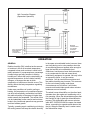
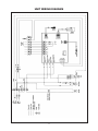
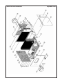
UNITARY PRODUCTS
GROUP
WHOLE HOUSE
DEHUMIDIFIER
Installation, Operating, and
Maintenance Manual
Installation, Operation, and Maintenance Instructions
Contents
Page
1. Safety .......................................................................... 2
a.Labeling ................................................................... 2
b.Instructions .............................................................. 2
2. Storage ....................................................................... 3
3. Specifications ............................................................. 3
4. Installing the Equipment ............................................. 3
a.Unit Location ........................................................... 3
b.Mounting .................................................................. 3
c.Condensate Drain ................................................... 4
d.Ducts ........................................................................ 4
5. Electrical ..................................................................... 4
a.Power Wiring ........................................................... 5
b.(Alternate) Remote Dehumidistat ............................ 5
c.Controls Connections .............................................. 6
d.Damper Connection ................................................ 7
6. Operation .................................................................... 8
a.General .................................................................... 8
b.Process .................................................................... 9
c.Sequence ................................................................ 9
i.Unit controls ........................................................... 9
ii. Wall control ........................................................ 10
iii. Frost control ...................................................... 10
d.Initial Set Up .......................................................... 10
7. Maintenance ............................................................. 11
a.Filter ....................................................................... 11
8. Wiring Diagram ......................................................... 11
9. Troubleshooting ........................................................ 12
10. Physical Dimensions .................................................12
SAFETY LABELING
SAFETY INSTRUCTIONS
DANGER!, WARNING! and CAUTION!
WARNING!
This dehumidifier must be installed by a qualified heating,
ventilation, and air conditioning professional in
compliance with all codes, local and national. Failure to
comply with this WARNING! could result in severe
personal injury or death.
These words are used to identify levels of hazard
seriousness as follows:
DANGER! Signifies an immediate hazard which will
result in severe personal injury or death.
WARNING!
Electrical shock hazard. Disconnect electrical power
before starting installation.
WARNING! signifies hazards or unsafe practices which
could result in severe personal injury or death
WARNING!
Equipment must be grounded electrically in compliance
with National Electric Code and local codes.
CAUTION! Signifies hazards or unsafe practices which
could result in minor personal injury or product and/or
property damage.
WARNING!
Handle unit with care using adequate manpower or
equipment to lift and avoid injury to personnel and/or
equipment.
CAUTION!
Failure to install this dehumidifier in compliance with
the instructions contained herein, could result in
unsatisfactory operation and/or damage to the product.
CAUTION!
Unit must be installed in compliance with all codes.
CAUTION!
For proper operation, external static pressures across the
unit must not exceed .6 in. w.c.
2
SPECIFICATIONS
Capacity
Unit Power Supply
Minimum Circuit Ampacity
Maximum Fuse
Dimensions
Weight
Compressor
Refrigerant
Fan Motor
Air Flow
Filter
Cabinet Insulation
Duct Connection
Drain Pan
Pints per day @ 80°F DBT/60% RH
Volts/Phase/Hz
13.1
15 amp
Length (overall)
Length (cabinet only)
Width
Height
Pounds net
Qty/Type
Watts/RLA/LRA
Qty/HP/FLA
CFM @ .6 in. w.c. e.s.p.
Type/size(in.)
Type/thickness
R Value
Inlet/Outlet
Material
STORAGE
130
115/1/60
30.00 in. (includes duct collars)
24.00 in.
25.25 in.
20.50 in.
150
1/Rotary
1070/9.5/61
R22
1/0.1/1.15
400
Washable nylon/17x23.5
EPDM/1 in.
4.2
8 in. diameter duct
Stainless steel
Place the unit in a location that will allow a
minimum of 22" clearance for filter removal and
service access. This clearance is required on only
one side of the unit since the filter is removable
from either side. Allow adequate clearance to
walls for normal unit service.
Temporary storage must be indoors, upright in the
original carton, and completely shielded from
precipitation.
CAUTION!
INSTALLING THE EQUIPMENT
Do not install the unit outdoors or in a
location where it will be subjected to
precipitation of any kind.
UNIT LOCATION
Unit location is very important as it will determine
the overall length of the connection ducts. Locate
the unit as close as possible to the indoor portion
of the resident’s air conditioning unit or air
handling unit, in the attic, basement, garage, or
equipment room. The dehumidifier may be placed
above, below or level with the air handing unit;
however, removal of condensate must be
considered when determining the location.
MOUNTING
The unit may be mounted on a flat surface or
suspended. If mounted on a flat surface use the
four rubber mounting feet provided. To minimize
unwanted vibration select a level mounting
surface. Adjust the four mounting feet to
compensate for any irregularities in the surface.
Ensure that the unit is sitting on all four feet. To
suspend the unit a separate hanger kit (S1-DEHUHGKIT)
is required. This kit consists of four brackets and
four rubber isolators. Threaded rod or other
means of suspension must be provided by the
installing contractor and must be selected based
on the unit weight, in compliance with local codes.
If the unit is mounted above a ceiling or in an
attic, a secondary drain pan under the entire unit
is recommended. This pan should have a visible
overflow drain that will alert the end user that a
problem exists with dehumidifier’s primary
drainage system.
3
be in compliance with local codes and be
complete, tight, and leak free.
Suspended unit utilizing
optional hanging kit
Ducts should be as short as possible, not to
exceed 100 ft. equivalent length and supported in
compliance with the manufacturer’s
recommendation.
CAUTION!
All duct connections must be sealed. Any
leakage in the duct work will adversely affect
the operation of the dehumidifier and may
lead to unsatisfactory performance.
DAMPERS
Optional dampers may be installed in the outlet
duct, inlet duct, or in an outside air duct. These
dampers must be full flow motorized type. Do not
use any type of pressure operated damper as
unacceptable pressure drop will affect unit
operation. All dampers must be installed in
compliance with the manufacturer’s
recommendations and be insulated, and sealed
per the section on ducts, above.
CONDENSATE DRAIN
ELECTRICAL
The condensate drain must be trapped external to
the unit. The trap dimensions must be equivalent
to the dimension of the trap on the associated air
conditioner air handling unit to prevent water
being removed from the trap when the A/C unit is
running.
POWER WIRING
WARNING!
Turn off electrical power at the fuse or
service panel before making any electrical
connections. The ground connection must
be completed before making line voltage
connections. Failure to do so can result in
electrical shock, severe personal injury or
death. The dehumidifier must be installed so
that the electrical components are protected
from water from any source.
A drain line must be attached to the trap outlet
and pitched away from the unit a minimum of 1/8"
per foot to allow the condensate to flow away
from the unit.
DUCTS
The unit is furnished with two beaded 8" round
collars for duct connections to the inlet and the
outlet of the dehumidifier. These are located
inside the unit and must be attached to the unit by
the installer using screws and gasket or caulking.
Center the collars over the inlet and outlet
openings in the cabinet.
WARNING!
The cabinet must be permanently
grounded. Connect the ground wire to the
Ground terminal provided in the unit. Failure
to ground the cabinet can result in fire,
electrical shock, personal injury or death.
Insulated flexible ducts in compliance with
Underwriter’s Laboratory’s (UL) Standard for
Factory Made Duct Materials, UL-18 and installed
per the manufacturer’s recommendation should
be used to connect the dehumidifier to the air
conditioner. The installation and connections must
The electrical supply requirements are listed on
the unit rating plate and in the specification table
above.
4
Use a separate fused branch electrical circuit
containing a properly sized fuse or circuit breaker.
Run this circuit directly from the main circuit box
to an electrical disconnect which must be readily
accessible and located within sight of the
dehumidifier. Connect from the disconnect to the
electrical connection within the dehumidifier
utilizing the hole sized for 1/2" conduit provided
on the entering air end of the unit.
local building/electric codes, using copper
conductors only.
(ALTERNATE) REMOTE DEHUMIDISTAT
The dehumidifier is supplied with its own, self
contained, dehumidistat control which includes an
air sampling sequence; however, the unit can also
be controlled by a remote dehumidistat located in
a conditioned space. DO NOT LOCATE THE
DEHUMIDISTAT IN THE DUCTWORK. It is
recommended that the remote dehumidistat, if
used, be located in an area close to the air
conditioner thermostat, out of drafts, away from
heat sources, and out of direct sunlight. It should
be located approximately 5 feet above the floor in
an area with good air circulation at average
temperature and relative humidity.
WARNING!
L (hot) and N (neutral) polarity must be
observed when making the electrical
connection to the unit.
Installation of the electrical supply line must be in
accordance with the National Electric Code, ANSI/
NFPA No. 70, latest edition, or Canadian
Electrical Code Part 1-CSA Standard C22.1 and
Remove the jumper on terminals S1 and S2 and
connect the remote dehumidistat as shown on the
unit connection diagram.
INSTALLATION OPTIONS
The dehumidifier can be connected so that the dehumidifier and the central air
conditioner fan operate totally independent of each other (independent
operation) or it can be connected in such a manner as to require that the
dehumidifier and the central fan operate simultaneously (dependent operation).
INDEPENDENT OPERATION
Dehumidifier Connected for Independent
Operation with Horizontal Air Handler/Furnace
DUCT CONNECTIONS (Independent
Operation)
In this arrangement, the dehumidifier is connected
across, or in parallel with the air conditioner air
handler. The discharge of the dehumidifier is
connected to the discharge of the air handler, and
the inlet connection of the dehumidifier is
connected to the inlet duct of the air handler.
When the dehumidifier is connected for
independent operation, the central air conditioner
fan and the dehumidifier fan CANNOT operate
simultaneously.
• Dehumidifier installed in attic (sitting on floor or
suspended from roof rafters
• Piped parallel to air handler
• Independent operation (furnace blower and
dehumidifier do not operate at the same time)
5
• Turn off the air conditioner fan, during
dehumidifier operation, if the FAN switch on
room thermostat has been placed in the ON
position for continuous operation
Dehumidifier Connected for Independent
Operation with Vertical Air Handler/Furnace
Five wires run from the air handler/furnace to the
dehumidifier to accomplish this interface, per Unit
Connection Diagram (Independent Operation)
and per the following:
DEHUMIDIFIER
• Connect the C, W, and Y terminals on the
dehumidifier unit to the corresponding
terminal on the air conditioner. Do not
disconnect any of the existing wires from the
C, W, or Y terminals on the air handler/
furnace.
• Dehumidifier
suspended from
ceiling
• Piped parallel
to air handler
• Disconnect the existing thermostat wire from
the G terminal on the air handler/furnace.
Using a wire nut, splice this wire to a new wire
and then connect to the G1 terminal on the
dehumidifier.
• Independent operation (furnace blower and
dehumidifier do not operate at the same time)
CONTROLS CONNECTION (Independent
Operation)
• Connect the G2 terminal on the dehumidifier
to the G terminal on the air handler/furnace.
The dehumidifier controls must interface with the
main air conditioning unit. This interface is
required to do the following:
All controls wiring, including connection to a
remote dehumidistat, must be 18-22 gauge and
must meet national and local electrical codes.
Entry into the dehumidifier unit is through a 7/8"
diameter hole located on the air entry end of the
unit, adjacent to the unit mounted dehumidistat.
Note that this is separate from the power entry.
• Turn off the dehumidifier if the air conditioning
unit is in the heating mode
• Turn off the dehumidifier if the air conditioning
unit is in the cooling mode
Unit Connection Diagram
(Independent Operation)
MODEL NUMBER
S1-DEHUMDKIT
AIR HANDLER/FURNACE
REMOVE
JUMPER ON S1
& S2 WHEN
OPTIONAL
DEHUMIDISTAT
IS USED
WALL-MOUNTED
DEHUMIDISTAT
S1-DEHUSTAT
(OPTIONAL)
6
these devices must be provided with a separate
transformer, not from the transformer located in
the dehumidifier.
DAMPER CONNECTION
If an optional damper(s) is used in the discharge/
return duct, this may be controlled by the
dehumidifier. See Unit Connection Diagram
(Independent Operation) for connection details.
When connected as shown in the Unit Connection
Diagram, the dehumidifier provides only the
switching interface for the damper(s). Power for
The damper control wiring must meet national
and local electrical codes. Entry into the
dehumidifier unit is through the control wire entry
located on the air-entering end of the unit. Note
that this is separate from the power entry.
DEPENDENT OPERATION
Connection Diagram (Dependent Operation) and
per the following:
DUCT CONNECTION (Dependent Operation)
In this arrangement, the dehumidifier is connected
either upstream or downstream of the air
conditioner air handler. Both the discharge and
the return of the dehumidifier are connected to
the same side of the air handler. When the
dehumidifier is connected for dependent
operation, the central air conditioner fan and the
dehumidifier fan MUST operate simultaneously.
• Connect the D terminals on the dehumidifier
unit to the R terminal on the air handler/
furnace. Do not disconnect any of the existing
wires from the air conditioning unit.
• Connect the DH terminal on the dehumidifier
to the G terminal on the air handler/furnace.
Do not disconnect any of the existing wires
from the air conditioning unit.
Dehumidifier Connected for Dependent Operation
with Vertical Air Handler/Furnace
All controls wiring, including connection to a
remote dehumidistat, must be 18-22 gauge and
must meet national and local electrical codes.
Entry into the dehumidifier unit is through a 7/8"
diameter hole located on the air entry end of the
unit, adjacent to the unit mounted dehumidistat.
Note that this is separate from the power entry.
DAMPER CONNECTION (Dependent
Operation)
DEHUMIDIFIER
Although not necessary, if an optional damper(s)
is utilized in the discharge/return duct, this may be
controlled by the dehumidifier. See Unit
Connection Diagram (Dependent Operation) for
connection details. When connected as shown in
the Unit Connection Diagram, the dehumidifier
provides the switching interface for the damper(s)
as well as the line voltage power to the
transformer (by others). Power for the damper(s)
is provided by the dehumidifier.
• Dehumidifier installed on floor
• Piped return/return
• Dependent operation (furnace blower and
dehumidifier must operate at the same time)
CONTROLS CONNECTION
(Dependent Operation)—Illustration on page 8
The dehumidifier controls must interface with the
main air conditioning unit. This interface is
required to do the following:
The damper control wiring must meet national
and local electrical codes. Entry into the
dehumidifier unit is through the control wire entry
located on the air-entering end of the unit. Note
that this is separate from the power entry.
• Ensure that the air handler/furnace fan is on
when the dehumidifier is operating
Two wires run from the air conditioner to the
dehumidifier to accomplish this interface, per Unit
See Illustration on page 8
7
Unit Connection Diagram
(Dependent Operation)
S1-DEHUMDKIT
REMOVE
JUMPER ON S1
& S2 WHEN
OPTIONAL
DEHUMIDISTAT
IS USED
WALL-MOUNTED
DEHUMIDISTAT
(OPTIONAL)
S1-DEHUSTAT
OPERATION
GENERAL
in the space at comfortable levels; however, there
are times during cool or rainy weather when the
air conditioning does not operate often enough to
keep the humidity at a comfortable level.
Oftentimes, homeowners lower the thermostat to
try to compensate for this and cause the air
conditioning equipment to operate. Not only is this
an expensive option, it may be counter
productive. Cool air can hold less moisture and
the relative humidity may increase. This accounts
for the cool clammy feeling under these
circumstances and, left alone, it will further
promote mold and mildew growth when moisture
condenses on cool surfaces.
Relative humidity (RH) is defined as the amount
of moisture in the air at a certain temperature
compared to how much moisture it could hold if
totally saturated. It is expressed as a percentage.
Human beings are fairly sensitive to relative
humidity as it affects the body’s natural ability to
regulate temperature. As the relative humidity
changes, so changes the rate at which
evaporation of moisture on the skin occurs. This
directly affects the body temperature regulating
mechanisms.
Under many conditions of comfort cooling or
heating, the temperature of a conditioned space
can be at a theoretically comfortable level while
the relative humidity of the space is higher than
would normally be acceptable. The results of this
can be inadequate human comfort and moisture
levels in the conditioned space that may promote
mold and mildew growth.
The whole house dehumidifier, on the other hand,
operates when the regular air conditioning unit is
not operating. When the dehumidistat senses that
the humidity is high it starts the dehumidification
process. The dehumidifier will remove moisture
while NOT OVERCOOLING the space. As stated
above, overcooling is expensive and does not do
the job. When the humidity level is under control,
the dehumidifier stops.
Typically, operating an air conditioning unit during
the cooling season will keep the relative humidity
8
discharge air temperature to be warmer than the
entering air temperature. The amount of this
temperature increase varies and is dependent
upon the load (how much dehumidification is
being done).
In southern climates, often the heating and air
conditioning equipment is turned off if the
residence is to be unoccupied for an extended
period of time. It is recommended that the
dehumidifier be left ON even when the air
conditioning is off. The internal fan in the
dehumidifier will move air throughout the
conditioned space to keep the humidity under
control. Since the dehumidifier adds a small
amount of heat to the space, it is recommended
that the air conditioning and the dehumidifier be
left on during unoccupied periods; however, the
set point of the air conditioning unit should be set
HIGHER than normal. The higher temperature will
lower the relative humidity. This, coupled with the
dehumidifier operation, will ensure a dry
conditioned space.
To ensure that the dehumidification process is
maximized, a thermostatic expansion valve is
used as part of the refrigeration system. This
device provides exacting control of the system
over a very wide range of operating temperatures.
This is superior to lower cost refrigerant control
devices such as capillary tubes which limit
efficient operation to a very narrow band of
operating temperatures.
SEQUENCE
Unit Controls
PROCESS
If no wall mounted dehumidistat is used, the unit
will be controlled by the integral control system.
This system operates the internal fan for 15
minutes approximately every hour to “sample” the
air in the system. The air sample passes over the
unit mounted humidity sensor. The unit mounted
control should be set at approximately mid level. If
the humidity level in the sampled air is greater
than the set point, the compressor will be turned
on, after a 3 minute delay. The fan and the
compressor will operate until the humidity level of
the air entering the dehumidifier satisfies the
humidity sensor/setpoint.
When the dehumidifier fan (blower) is operating,
moist air from the conditioned space is drawn into
the unit through the inlet duct. The air first passes
through the filter in the unit. Once beyond the
filter, the air passes through the cool evaporator
(cooling) coil. This coil is part of the refrigeration
process and is, therefore, cold. In all probability
the coil is colder than the dew point of the air.
Since it is below the dew point, moisture in the air
will condense on the coil fins. Once condensed
out of the circulating air, the moisture now in the
form of droplets falls to the bottom of the coil and
is collected in the drain pan. This is essentially the
same process that causes water to drip from
beneath an automobile when the air conditioning
is operating.
Wall Control
When this control method is selected, the unit
mounted control must be adjusted to its minimum
(lowest relative humidity) level and never
readjusted. The room dehumidistat should be set
in the comfort area at approximately 50% RH
(relative humidity). When the dehumidistat senses
that the RH in the space is above its set point, an
electrical contact within the dehumidistat closes
causing the dehumidifier to start. The unit runs to
dehumidify the air from the conditioned space
until the
dehumidistat is
satisfied, that is,
the RH has been
lowered to the set
point.
Once the moisture has been removed from the
air, it is somewhat cooler. However, since the air
is cooler it cannot hold as much moisture and its
relative humidity is high, even though moisture
has been removed. To solve this “problem” the air
next passes through a warm condenser (heating)
coil where it is warmed. Since the air is warmed
without adding any moisture, its relative humidity
decreases sharply. This dry air is drawn through
the fan and then expelled through the discharge
duct back to the conditioned space.
Dehumidifiers take latent heat (heat removed
from water vapor when it condenses) and convert
it to sensible heat (heat you can feel in the form of
temperature increase). This exchange causes the
Wall Mounted
Dehumidistat
9
Frost Control
Occasionally, frost will accumulate on the coil in
the unit. This is not abnormal and may result from
prolonged operation or if the conditioned space is
relatively cool. If allowed to go unchecked, ice will
eventually cover the coil, blocking air flow and
interrupting proper operation of the unit. To
prevent frost build-up beyond an acceptable level,
a sensor mounted on the coil will stop compressor operation if the coil becomes unacceptably cold and remains there for at least 10
minutes. The fan will continue to operate to melt
any accumulated ice. Once the ice has melted
and the coil is warm, the compressor will restart
and the dehumidification process will resume.
INITIAL SET UP
recommended that all adjustments be made in no
more than 3% increments at no less than 24 hour
intervals.
Insure that power to the dehumidifier unit is
turned on. For unit control, adjust the set point
knob to approximately 60% RH. For wall control,
adjust the unit mounted control to its minimum
(lowest RH) setting and set the wall mounted
dehumidistat to a desired level. It is
recommended that it be set at approximately 60%
at first and then adjusted no sooner than 24 hours
later to a higher or lower set point as desired. It is
Depending upon the conditions, the dehumidifier
may operate for extended periods, especially
when first started or after having been off. This is
not abnormal and something for which the
dehumidifier is designed.
MAINTENANCE
FILTER
H
The dehumidifier unit is equipped with a
permanent nylon mesh air filter. This filter is
washable and should be cleaned regularly, along
with the air conditioner filter replacement. If it
appears that the filter has become excessively
dirty when cleaned at this interval, it may be
necessary to adjust the cleaning schedule to
more frequent cleaning. Excess dirt on the filter
will reduce the air that can flow through it and
reduce the overall effectiveness of the
dehumidifier.
Filter Replacement
The unit Wiring Diagram is shown on page 11
and the Troubleshooting Guide is on page 12.
10
UNIT WIRING DIAGRAM
11
TROUBLESHOOTING
PROBLEM
Dehumidifier will not run
Dehumidifier operates
continuously but does not
dehumidify
Unit is noisy
Water drips from unit
Heat/AC unit is OFF, but
dehumidifier runs
POSSIBLE SOLUTION
• Verify there is power to the unit
• Check that any disconnect switch is ON
• Check that the circuit breaker is not tripped (a separate 15 amp
circuit breaker is recommended)
• Verify the dehumidistat is not in the OFF position
• Verify low voltage wiring between AC and dehumidifier is correct
• Unit door switch is not mechanically actuated due to loose door.
• Filter may be dirty. Clean filter
• Dehumidistat set at unrealistically low setting. Reset to
approximately 50% RH
• Ensure unit is sitting level and on all four feet
• Verify all panel screws are tight
• Ensure unit is level
• Verify condensate drain is properly trapped
• Check for plugged condensate trap or condensate line
• This is normal operation as long as there is power to the
dehumidifier.
Unit Dimensions
All specifications and performance data subject to change without notice.
12
Whole House Dehumidifier
Exploded View
13
Whole House Dehumidifier
ITEM
NUMBER
Parts List
DESCRIPTION
QTY
1
7410
D114 DUCT, SUPPLY
1
2
7411
VB14 PANEL, BLOWER SUPPLY w/ INSULATION
1
3
7412
BM14 BASE, MOTOR
1
4
7413
MT14 MOTOR - 115V, 1/10 HP, 3 SPD
1
5
7414
BW14 BLOWER SET (WHEEL, HOUSING & INLET)
1
6
7415
RC14 CAPACITOR, (MOTOR)
1
7
7416
DP14 DRAIN PAN (STAINLESS)
1
8
7417
SM14 PANEL SIDE w/ INSULATION
1
9
7418
CO14 COI
1
10
7419
FT14 FILTER, 431x 595 x 5 mm, NYLON
1
11
7420
UF14 UPPER GROOVE, FILTER
1
12
7421
DR14 DUCT, RETURN
1
13
7422
TR14 TRANSFORMER, 115-24VAC, 24VA
1
14
7423
VR14 PANEL, RETURN AIR w/ INSULATION
1
15
7424
LF14 LOWER GROOVE FILTER
1
16
7425
SR14 SUPPORT, SIDE PANEL RETURN AIR
1
17
7426
TX14 TEX VALVE
1
18
7427
FD14 FILTER DRIER
1
19
7428
CS14 COMPRESSOR
1
20
7429
BT14 BOTTOM PAN
1
21
7430
SD14 PANEL, SIDE w/ INSULATION
1
22
7431
SP14 PANEL, FILTER w/ INSULATION
2
23
7432
PP14 PCB, MAIN
1
24
7433
HC14 SENSOR MODULE, HUMIDITY W/ HARNESS
1
25
7434
NC14 KNOB, CONTROL
1
26
7435
RI14 ISOLATOR, RUBBER
4
27
7436
AF14 FOOT, RUBBER, ADJUSTABLE
4
28
7437
DS14 SWITCH, DOOR
1
29
7438
CT14 PANEL, CONTROL
1
30, 31
7439
MH14 GROMMET, RUBBER, CLOSED, 7/8" OD
1
32
7440
RH14 POT, RH ADJUSTMENT, w/ HARNESS
1
33
7441
TP14 PANEL, TOP w/ INSULATION
1
34
7442
HG14 HANGER
4
35
7443
TS14 TERMINAL STRIP, TB-10, 5 AMP
1
36
7444
TS14-1 TERMINAL STRIP, TB-6, 30 AMP
1
37
7445
RC14-1 CAPACITOR, (COMPRESSOR)
1
38
7446
DF14 DEFROST SENSOR w/ HARNESS
1
14
LIMITED WARRANTY
The model S1-DEHU130 dehumidifier, if properly registered by the return of the attached warranty registration to Unitary Products Group, is warranted to
the consumer against defects in materials and workmanship for a period of five years from the date of installation, so long as the product has been
installed and operated in accordance with all appropriate manuals and wiring diagrams. Any other defective parts will be repaired without charge
except for removal, reinstallation and transportation costs. To obtain repair service under this limited warranty, the consumer must send the defective
part to Unitary Products Group.
THERE ARE NOT EXPRESS WARRANTIES COVERING THIS HUMIDIFIER OTHER THAN AS SET FORTH ABOVE. THE IMPLIED WARRANTIES
OF MERCHANTABILITY AND FITNESS FOR A PARTICULAR PURPOSE ARE EXPRESSLY EXCLUDED. THE MANUFACTURER ASSUMES
NO LIABILITY IN CONNECTION WITH THE INSTALLATION OR USE OF THIS PRODUCT, EXCEPT AS STATED IN THE LIMITED WARRANTY.
THE MANUFACTURER WILL IN NO EVENT BE LIABLE FOR INCIDENTAL OR CONSEQUENTIAL DAMAGES.
This limited warranty gives you specific legal rights, and you may also have other rights which vary from state to state. Some states do not allow either
limitations on implied warranties, or exclusions from incidental or consequential damages, so the above exclusion and limitation may not apply to you.
Any questions pertaining to this limited warranty should be addressed to Unitary Products Group. The Unitary Products Group has elected not to
make available the informal dispute settlement mechanism which is specified in the Magnuson-Moss Warranty Act.
Unitary Products Group
5005 York Drive
Norman OK, 73069
www.source1parts.com
Tel. 1-800-536-6112
15
WARRANTY REGISTRATION
Enregistrement de la garantie
MODEL S1-DEHU130
MODÈLE S1-DEHU130
OWNER'S NAME
Nom du propriétaire:
STREET ADDRESS
Adresse:
CITY
Ville:
DEALER'S NAME
Nom du marchand:
STREET ADDRESS
Adresse:
CITY
Ville:
DATE OF INSTALLATION
DATE DE INSTALLATION
STATE
Province:
POSTAL CODE
Code postal:
STATE
Province:
POSTAL CODE
Code postal:
SERIAL NUMBER
NUMÉRO DE SÉRIE
Design, material, performance data and components
subject to change without notice.
UNITARY PRODUCTS GROUP
5005 YORK DRIVE
NORMAN OK, 73069
12/14/06 Rev. A
FORM# 16007