1
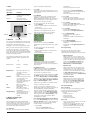
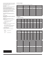
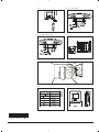
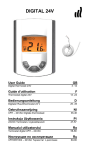
U SER M AN U AL
Warmup Thermostat type WA-TSTAT-V
57628 09/06 (BJ)
Contents
1.
2.
3.
4.
5.
6.
Language
English .
G erman .
French .
Portuguese
.
.
.
.
.
.
.
.
.
.
.
.
.
.
.
.
.
.
.
.
page
1-4
page
5-8
page 9 - 12
page 13 - 16
Introduction
. . . . . . . . . .
G etting started . . . . . . . . . .
G eneral Display . . . . . . . . . .
LE D
. . . . . . . . . .
Buttons
. . . . . . . . . .
Menus for Setting U p the Thermostat
. . . .
6.1.
O peration . . . . . . . . . .
6.1.1. Auto . . . . . . . . .
6.1.2. Manual
. . . . . . . .
6.1.3. C omfort . . . . . . . .
6.2.
Setting 4-event . . . . . . . .
6.2.1. Example of Scheduling 4-event Set-up
6.3.
Programming . . . . . . . . .
6.4.
G eneral Settings . . . . . . . .
6.4.1. Language . . . . . . . .
6.4.2. Time . . . . . . . . .
6.4.3. Day
. . . . . . . . .
6.4.4. Temperature . . . . . . .
6.4.5. C hild lock . . . . . . . .
6.4.6. H eater . . . . . . . . .
6.4.7. C overing . . . . . . . .
6.4.8. Sub Floor . . . . . . . .
6.4.9. Application
. . . . . . .
6.5.
Service
. . . . . . . . . .
6.6.
C ontact Details . . . . . . . .
6.7.
Engineer Settings . . . . . . . .
6.7.1. Readout . . . . . . . .
6.7.2. Temp. Settings
. . . . . .
6.7.3. Adaptive function . . . . . .
6.7.4. Offset . . . . . . . . .
6.7.5. Fil Pilote* . . . . . . . .
6.7.6. Reset . . . . . . . . .
7. Error Messages . . . . . . . . . .
8. F actory settings . . . . . . . . . .
9. Appendix
. . . . . . . . . .
9.1.
Table of C ompatibility . . . . . . .
9.2.
H eat Definitions . . . . . . . .
1. Introduction
2. Getting started
The N ewStar thermostat can switch on your
heating system at pre-determined times on
different days of the week. It is possible to set 4
periods called events each day with different
temperatures. The thermostat comes with a
default schedule that is suitable for most
installations. Unless you change these settings,
the thermostat will operate to this default
program.
Q uick set-up:
The first time you connect the power or after a
reset, the display will show you “Welcome to
Warmup”.
Working with lower temperatures during times
that the room is unoccupied will lower your
energy costs without reducing the comfort. The
thermostat has an adaptive function that
automatically changes the start time of a
heating period so that the desired temperature
is reached at the time that you set. After 3 days
the adaptive function has learned when the
heating must be switched on.
Push accept button. Then you can select:
• Language
• Time
• Day
• Temperature
• C hild lock
• H eater?
• C overing?
• Sub floor
• Application
Use the navigation buttons for selecting /
changing in the menus.
Important:
You have, as minimum, to select “H eater” and
“covering” to define the type of heater and
covering, before you can start up the
thermostat.
F or further information, see point:
5. Buttons.
6.4. G eneral settings.
Type: WA-TSTAT-V
.
.
.
.
.
.
.
.
.
.
.
.
.
.
.
.
.
.
.
.
.
.
.
.
.
.
.
.
.
.
.
.
.
.
.
.
.
.
.
.
.
.
.
.
.
.
.
.
.
.
.
.
.
.
.
.
.
.
.
.
.
.
.
.
.
.
.
.
.
.
.
.
.
.
.
.
.
.
.
.
.
.
.
.
.
.
.
.
.
.
.
.
.
.
.
.
.
.
.
.
.
.
.
.
.
.
.
.
.
.
.
.
.
.
.
.
.
.
.
.
.
.
.
.
.
.
.
.
.
.
.
.
.
.
.
.
.
.
.
.
.
.
.
.
.
.
.
.
.
.
.
.
.
.
.
.
.
.
.
.
.
.
.
.
.
.
.
.
.
.
.
.
.
.
.
.
.
.
.
.
.
.
.
.
.
.
.
.
.
.
.
.
.
.
.
.
.
.
.
.
.
.
.
.
.
.
.
.
.
.
.
.
.
.
.
.
.
.
.
.
.
.
.
.
.
.
.
.
.
.
.
.
.
.
.
.
.
.
.
.
.
.
.
.
.
.
.
.
.
.
.
.
.
.
.
.
.
.
.
.
.
.
.
.
.
.
.
.
.
.
.
.
.
.
.
.
.
.
.
.
.
.
.
.
.
.
.
.
.
.
.
.
.
.
.
.
.
.
.
.
.
.
.
.
.
.
.
.
.
.
.
.
.
.
.
.
.
.
.
.
.
.
.
.
.
.
.
.
.
.
.
.
.
.
.
.
.
.
.
.
.
.
.
.
.
.
.
.
.
.
.
.
.
.
.
.
.
.
.
.
.
.
.
.
.
.
.
.
.
.
.
.
.
.
.
.
.
.
.
.
.
.
.
.
.
.
.
.
.
.
.
.
.
.
.
.
.
.
.
.
.
.
.
.
.
.
.
.
.
.
.
.
.
.
.
.
.
.
.
.
.
.
.
.
.
.
.
.
.
.
.
.
.
.
.
.
.
.
.
.
.
.
.
.
.
.
.
.
.
.
.
.
.
.
.
.
.
.
.
.
.
.
.
.
.
.
.
.
.
.
.
.
.
.
.
.
.
.
.
.
.
1
1
1
2
2
2
2
2
2
2
2
2
2
2
2
2
3
3
3
3
3
3
3
3
3
3
3
3
3
4
4
4
4
4
4
4
4
3. General Display
The display will normally
show the period (day, night,
home, out), the current
temperature, and the time.
The period is indicated by a symbol. B elow you
can see a list of some of the symbols:
At work
At home
Day
Night
4. LED
ways of setting the temperature(s):
The LE D is placed in the top right corner above
the display.
6.1.1. Auto
Select Auto if you want the temperature to be
controlled and operated automatically via the 4event system.
LED signal
C onstant red light
Blinks
No light
Indicates
Relay is active
System failure. (see error
messages)
Relay not active or
thermostat turned off
LE D
Reset
Standby
5. Buttons
6.1.2. Manual
H ere you can cancel the scheduled 4-event
program (e.g. during holidays) and set the
wanted temperature manually. You may want to
adjust the temperature to for example 5°C for
frost protection while you are away.
To set the temperature, do the following:
1. Select Manual.
2. Use the up/down button to raise/lower the
temperature.
3. Press the Accept button to finish.
Please note: The temperature that you set
manually will be valid until you cancel the
manual mode again by selecting Auto.
N avigation
You can use the standby button to turn display
and regulation of temperature on/off. When the
thermostat is switched off, the relay
disengages. The clock will keep going, though.
6.1.3. Comfort
H ere you can set a temporary Comfort
temperature (so-called party mode) for a single
event.
When you press the Reset button (use pen to
activate) for 3 seconds, a " C onfirm factory
reset " text will be shown on the display. Then
press the Accept button to reset the thermostat,
which will then start up with default values and
display the installation menu.
To set the temperature, do the following:
1. Select Comfort.
2. Use the up/down button to raise/lower the
temperature.
3. Press the Accept button to finish.
The buttons for navigating in the menus and
selecting/changing settings are placed in the
middle.
Up
B ack/ C ancel
Accept
F orward
Down
• G o back in the menus (i.e.
upwards in the menu
hierarchy).
• C ancel changes of current
value.
Forward
• Move forward in the menus
(i.e. downwards in the
menu hierarchy).
• Q uick steps upwards when
specifying values, e.g.
temperature.
Up
• Move up in menu.
• Raise current value, e.g.
temperature.
Down
• Move down in menu.
• Lower current value, e.g.
temperature.
Accept/Change • Select item from menu to
see/change/set value.
• Accept new/changed
setting.
Back/Cancel
6. Menus for Setting Up
the Thermostat
You can program the thermostat and make
various settings by using the menu system. To
open the main menu, press the Accept button.
In the sections below every item on the main
menu will be described in more detail.
6.1. Operation
H ere you can choose between three different
Please note: C omfort mode is a temporary,
manual setting that will be automatically
cancelled by the next event in the scheduled 4event system.
6.2. Setting 4-event
If Auto has been selected in the Operation
menu, the 4-event system can be set to
automatically control the temperature settings
for each day in a period of 7 days.
You can select the wanted temperature for Day
and Night, for when you are O ut and at Home,
and for the Weekend Day and Weekend Night.
Moreover, you can define when you want each
time period (Day, Night, Out, Home, Weekend
Day, and Weekend Night) to begin.
Please note: You need to use the Down button
to move to the end of the menu.
Finally you can specify temperatures and
periods (Day, Night, O ut, Home) for each day of
the week (Monday, Tuesday, Wednesday,
Thursday, Friday, Saturday, and Sunday). This
requires, though, that the Mon-Sun, 4-events
option has been selected in the Programming
menu (will be shown as Programming: 7:0 on
the display). Please refer to section about
Programming on page 8.
6.2.1. Example of Scheduling 4-event Set-up
If you in the Programming menu have selected
Mon-Fri, Sat-Sun (shown as Programming: 5:2
on the display) you can set up the 4 periods
(called events) in the following way:
1. C hoose Day.
• Specify when Day time begins.
Use the up/down button to mark the
wanted time.
Press the Accept button to finish.
• Specify the wanted Day temperature.
Use the up/down button to raise/lower the
temperature.
Press the Accept button to finish.
2. C hoose Out.
• Specify when O ut time begins.
• Specify the wanted temperature when you
are out and away from home (O ut temp).
3. C hoose Home.
• Specify when Home time begins.
• Specify the wanted temperature when you
are at home (Home temp).
4. C hoose Night.
• Specify when Night time begins.
• Specify the wanted Night temperature.
5. C hoose Weekend Day.
• Specify when Day time begins on
weekends.
• Specify the wanted Day temperature on
weekends.
6. C hoose Weekend Night.
• Specify when Night time begins on
weekends.
• Specify the wanted Night temperature on
weekends.
6.3. Programming
H ere you can choose between various
programming options that are used in
connection with scheduling the 4-event system:
• Mon-Fri, Sat-Sun
Will be shown as 5:2 on the display. This
setting allows you to have 5 days with the
same 4-events, and 2 days with the same 2
events. The days 1-5 are controlled by the
settings for Day, Night, Out, Home and
day 6-7 is controlled by the settings for
Weekend Day and Weekend Night.
• Mon-Sat, Sun
Will be shown as 6:1 on the display. This
setting allows you to have 6 days with the
same 4-events, and 1 day with 2 events.
The days 1-6 are controlled by the settings
for Day, Night, Out, Home and day 7 is
controlled by the settings for Weekend Day
and Weekend Night.
• Mon-Sun, 4-events
Will be shown as 7:0 on the display. This
setting allows you to have 7 days with 4
different events (Day, Night, Out, Home).
The days 1-7 are controlled by individual
day settings (Monday – Sunday).
6.4. General Settings
6.4.1. Language
H ere you can select the language you want to
be used on the display. You can choose
between the following languages:
• English
• G erman (Deutsch)
• French (Francais)
• Spanish (Espanol)
• Portuguese (Portogese)
6.4.2. Time
• H ere you can select whether 12- or 24-hour
clock should be used.
• Further, you can set the time here. To set
the time, select Set time. Then use the
up/down buttons to adjust the time, and
press the Accept button to finish.
6.4.3. Day
H ere you can set the day of the week:
• Monday
• Tuesday
• Wednesday
• Thursday
• Friday
• Saturday
• Sunday
Please note: You need to use the Down button
to move to the end of the list of weekdays.
6.4.4. Temperature
Scale
H ere you can specify what temperature unit
should be used in the display:
• °C (C elsius, with a resolution of 0.5 degree)
• °F (F ahrenheit, with a resolution of 1
degree)
• A scale from 1-10 (in steps of about 10°).
Display shows
H ere you can decide whether the display shall
show the time, set point and/or air temperature.
• Time (O n/ Off)
• Set point (O n/ Off) (The current temperature
that the thermostat has been set to, for
instance in the 4-event settings.)
• Air Temp. (O n/ Off). The room/air
temperature currently registered by the
sensor.
Air temperature
Set point
Time
6.4.5. Child lock
By switching on the child lock you can lock the
menus (marked with a padlock symbol on the
display). Then it will no longer be possible to
select the sub-menus and change the settings.
You can still set a comfort temperature and the
time, though.
Please note: You can still use the Reset button
to return to factory settings, if the child lock has
been switched on.
6.4.6. Heater
H ere you can define the type of heater that the
thermostat is attached to:
• Wire
• Ribbon
• C arbon
• Radiator
• Type A
• Type B
• Type C
• User Defined
Please refer to Appendix for configuration table
showing combinations of heater type and
covering.
6.4.7. Covering
H ere you can enter the type of floor covering:
• C eramic Tiles
• Stone
• Laminate
• Wood
• C arpet
• Vinyl
• Other
Please refer to Appendix for configuration table
showing combinations of heater type and
covering.
6.4.8. Sub Floor
H ere you can enter the type of sub floor:
• C oncrete
• Screed
• W B P Ply
• Ins. B acker B oard
• B acker B oard
6.4.9. Application
H ere you can select the type of regulator
application:
• Floor Temp. Cont.: A floor sensor is used.
• Fl. Cont. 2 sensors: B oth floor sensor and
limit sensor are used. A maximum
temperature limit can be set for the limit
sensor, so the thermostat will switch off if
the temperature at the place of the limit
sensor reaches the maximum temperature.
This set-up with a limit sensor can, for
instance, be used to avoid damage to some
delicate floor covering.
• Air Temp. Control: The sensor is placed in
the thermostat.
• Air Cont. Floor limit: Apart from the sensor
inside the thermostat an extra limit sensor
is used. A maximum temperature limit can
be set for the limit sensor, so the thermostat
will switch off if the temperature at the
position of the limit sensor reaches the
maximum temperature. This set-up with an
extra limit sensor can, for instance, be used
to avoid damage to some delicate floor
covering.
• Regulator Control: No sensor is used here.
The thermostat will turn on in sequences of
20 minutes, and you can specify the length
of the sequences as a percentage of 20
minutes. If you, for example, set the
regulator to 50, the thermostat will turn on
for 10 minutes, switch off for 10 minutes,
and then turn on again for 10 minutes.
• External Control: Used in case of a set-up
with several thermostats being controlled
by an external master thermostat. Then the
thermostat will work as a slave, and you
cannot apply any settings at all since the
master thermostat controls it.
6.5. Service
If you need tecnical help then select Service
from the main menu to see the contact
information.
6.6. Contact Details
Select Contact Details from the main menu to
see the contact information.
Warmup plc
www.warmup.com
G B +442084536868
U SA +12037910072
E S +34800099988
PT +351800812080
F +33080563990
6.7. Engineer Settings
To select Engineer settings, press the up and
down button at the same time for 5 seconds.
Note: C hanges may invalidate warranty.
6.7.1. Readout
H ere you see readouts of the following current
temperatures:
• Room temp
• Floor temp
• Floor limit temp
You can also get readouts of some statistics:
• Min daily: A percentage indicating the
minimum activated period within 24 hours
over the last 14 days.
• Max daily: A percentage indicating the
maximum activated period within 24 hours
over the last 14 days.
• 2 Days: Indicates how many % the heater
has been turned on for the last two days.
• 30 Days: Indicates how many % the heater
has been turned on for the last 30 days.
• 360 Days: Indicates how many % the
heater has been turned on for the last 360
days.
• Min Air: Minimum room temperature within
the last 48 hours.
• Mean Air: Average room temperature
within the last 48 hours.
• Max Air: Maximum room temperature
within the last 48 hours.
• Min Floor: Minimum floor temperature
within the last 48 hours.
• Mean Floor: Average floor temperature
within the last 48 hours.
• Max Floor: Maximum floor temperature
within the last 48 hours.
• Cut out cnt: Number of relay connections
in the service life of the thermostat. This
value is never reset.
• Application: H ere you can get readout for
the current application type that has been
selected in the G eneral settings
- Floor
- Floor-2
- Air
- Air-Limit
- Reg.
- Ext.
• Software ver.: Indicates the current version
of the software.
6.7.2. Temp. Settings
H ere you can specify the wanted minimum and
maximum temperatures for air, floor, or external
limit sensor.
B efore you can select minimum and maximum
limits for air, floor or limit sensor, the application
for the regulator type in question must be
chosen. Please refer to section about G eneral
Settings – Application on page 11 for more
details.
Please note: If you do not specify any settings
here, the factory settings will be used.
• Air Temp. Range
Max Temp
Min Temp
• Floor Temp. Range
Max Temp
Min Temp
• Limit Sensor
Max Temp
Min Temp
6.7.3. Adaptive function
H ere you can activate/deactivate (O n/ Off) the
adaptive function. This function is only related
to the 4-event timer and only works in
connection with going from one event to
another where the temperature is going to be
raised. The adaptive function finds out when the
thermostat shall start heating to ensure that the
right temperature is reached at the time that it
has been programmed for.
6.7.4. Offset
Offset is used to compensate for any difference
between the thermostat and a room
thermometer. If the thermometer, for instance,
shows 1°C more than the thermostat, it is
possible to adjust the offset by +/- 5°C . Then
the thermostat will show the same temperature
as the thermometer. If the thermostat for
example shows 1 degree too much, offset
should be set to +1. Then the temperature will
be set 1 degree lower.
Offset applies to both built-in and external
sensors whereas the limit sensor, if any, is not
affected.
6.7.5. Fil Pilote*
H ere you can specify temperature settings that
will depend on which signal is received from the
Fil pilote input.
*Please note: The Fil pilote menu is only
available in type WA-STAT-VB. It is primarily for
usage in France.
• E co Temp: E conomic temperature
• Frost Prt T: Frost protection
• Fil Pilote: O n/ Off
6.7.6. Reset
• Reset 2: Reset values defined in Engineer
settings to factory settings.
• Reset 3: E qual to Reset 2, except history
data are deleted. The number of relay
connections is not deleted, though.
7. Error Messages
If you get an error the LE D is flashing red.
Internal
failure
C ontact Warmup
External
failure
C ontact Warmup
8. Factory settings
The thermostat is delivered with factory set programs as follows:
Day 1-5
Event
Time
With floor sensor
With air sensor
Day
06:00-08:00
25°C
20°C
O ut
08:00-16:00
20°C
15°C
Home
16:00-22:30
27°C
22°C
Night
22:30-06:00
20°C
15°C
Day 6-7
Event
Time
With air sensor
Day
08:00-23:00
27°C
22°C
Night
23:00-08:00
20°C
15°C
9. Appendix
9.1. Table of Compatibility
Tiles
Stone
Laminate
Wood
Carpet
Vinyl
Other
Wire
YES
YES
NO
NO
NO
NO
n/a
Ribbon Wire
YES
YES
YES
YES
NO
NO
n/a
Carbon
YES
YES
YES
YES
YES
YES
n/a
Central heating
n/a
n/a
n/a
n/a
n/a
n/a
n/a
Type A
YES
YES
NO
NO
NO
NO
n/a
Type B
NO
NO
YES
YES
NO
NO
n/a
Type C
NO
NO
NO
NO
YES
YES
n/a
User Defined
n/a
n/a
n/a
n/a
n/a
n/a
n/a
Tiles
Stone
Laminate
Wood
Carpet
Vinyl
Other
Wire
A
A
n/a
n/a
n/a
n/a
H
Ribbon Wire
A
A
B
B
n/a
n/a
H
Carbon
A
A
B
B
C
C
H
Central heating
G
G
G
G
G
G
H
Type A
D
D
n/a
n/a
n/a
n/a
H
Type B
n/a
n/a
E
E
n/a
n/a
H
Type C
n/a
n/a
n/a
n/a
F
F
H
H
H
H
H
H
H
H
9.2. Heat Definitions
User Defined
Configuration
Control temperature
Overheat
Room
Floor
Min. Max.
Min. Max.
Max.
A
5
40
5
40
40
B
5
27
5
27
30
C
5
25
5
25
30
D
5
40
5
50
55
E
5
27
5
45
50
F
5
25
5
G
5
45
H
5 7 6 2 8
With floor sensor
n/a = not available
prog
35
40
n/a
n/a
prog
prog
INS TRU C T IONS
Programmable Thermostat WA-XSTAT
57627B 11/06 (BJ)
English
The electronic comfort controller is a clock
thermostat that can be programmed to function
as a floor temperature controller and room
temperature controller with a limitation function.
The thermostat is intended for mounting in a
55 mm standard wall socket. The operating area
ranges from +0° to +30°C. The thermostat
incorporates a clock enabling the programming
of several setback functions.
Controller setting WA-XSTAT
Program choice:
Floor temperature control
Floor temperature control with 2 sensors
Air temperature control
Air temperature control with floor
temperature limit
Regulator control
External control
The controller is designed in accordance
with current product standard EN 607302-9, and fulfill hereby the requirements to both
LVD and EMC directives.
The controller must not be put into operation
until it has been ascertained that the entire
installation complies with current general safety
requirements for electrical installations.
The warranty is only valid if the controller has
been put into operation in accordance with the
operating instructions supplied with the
controller and these installation instructions.
Technical data
Supply voltage . . . . . . . . . . .230V ±15%, 50 Hz
Output relay SPST . . . . . . . . . . . . . .16A, 3600W
Temperature range . . . . . . . . . . . . . . . .+0/+30˚C
Temperature limitation . . . .min./max. +5/+55˚C
Clock function . . . .1 pre-installed programmes
28 optional setback programmes
Ambient temperature . . . . . . . . . . . . . . .0/+30˚C
On/off differential . . . . . . . . . . . . . . . . . . . .0,4˚C
Housing . . . . . . . . . . . . . . . . . . . . . . . . . . .IP 21
Sensor type . . . . . . . . . . . . . . . . . . . . . . . . .NTC
- heating is switched off in case of sensor failure
Dimensions (HxWxD) (fig. 6) . . . . .86/86/48 mm
The controller is maintenance-free.
Control pollution degree: 2
Pollution degree 2 is representative of normal
household air circulation.
Overvoltage category: III
Classification
The product is a class II device (reinforced
insulation) and the product must be connected
to the following conductors:
1) Phase (L)
2) Neutral (N)
The thermostat is constructed to store the clock
up to 4 hours at an occasional voltage
interruption. It is not suitable for use by regular
voltage interruptions. (Example: Power term
applications). At such conditions a constant
power supply for the thermostat must be
ensured.
Type WA-XSTAT
WARNING – Important Safety Instructions
Isolate supply before carrying out any
installation or maintenance work on this control
unit and associated components. This control
unit and associated components should only be
installed by a competent person (i, e qualified
electrician). Electrical installation to be in
accordance with latest IEE Wiring Regulations
and appropriate Statutory Regulations.
Mounting of sensor
Floor sensor: Placed in an approved non
conductive installation pipe in accordance with
EN 61386-1, which is embedded in the floor.
(fig. 3). The pipe is closed in the end and placed
as high as possible in the concrete layer. The
installation pipe must be centered in between
the heating cable.
The enclosed 3 meter sensor cable can be
extended up to 100 m by means of a separate
cable. If the extension cable is lighter than
H05VV-F, it shall equally be installed in an
unbroken installation pipe between the sensor
cable and the extension cable. Two remaining
cores of a multi-core cable which, for example,
supplies current to the heating wires of a floor
heating system, must not be used. The
switching peaks of such current supply lines
may create interfering signals that prevent
optimum controller function. The two-corecable
must be placed in a separate pipe.
Controller installation site
The controller must be mounted on the wall so
that air can circulate freely around it (fig. 4). An
installation site must be selected where the
controller is not exposed to foreign energy
sources, e.g. solar radiation. The controller must
not be exposed to draughts coming from, for
example, windows, doors or cold outer walls.
The controller has a built-in fault interrupter
circuit which interrupts the heating in case of
disconnected or short-circuited sensor.
Mounting of controller
The single gang mounting box must have a
debt of no less than 25 mm.
1. Use a screwdriver in both sides to open the
lock.
The cover must be dismounted (fig. 1).
2. Connect cables according to the diagram
(fig. 2a-2b).
All electrical connections must be performed by
a fully qualified and Part P certified electrician.
3. The thermostat is mounted in the wall
socket. The cover is remounted.
Programming
(See user manual)
The controllers are delivered with a pre-installed
setback programme.
If the pre-installed setback programme is not
used, there are different programmes which can
be selected and used on the required days.
The controllers calculate when the heating is to
be switched on to make sure that the comfort
temperature is obtained to the required time.
Fault location
If the sensor is disconnected or shortcircuited, the heating system is switched off.
The sensor can be checked according to the
resistance table fig. 5.
Environment and recycling
Please help us to protect the environment by
disposing of the packaging in accordance with
the national regulations for waste processing.
Recycling of obsolete appliances
Appliances with this label must not
be disposed off with the general
waste. They must be collected
separately and disposed off
according to local regulations.
NW107UW-A
Warmup Plc
702 Tudor Estate · Abbey Road
London NW10 7UW
T. +44 845 345 2288
F. +44 845 345 2299
warmup.com
Español
El controlador electrónico de confort es un
termostato cronometrado que se puede
programar para funcionar como controlador de
temperatura del piso y como controlador de
temperatura ambiente con una función
limitadora.
El termostato está diseñado para montaje en un
receptáculo de pared estándar de 55 mm. Los
límites de funcionamiento son de 0° a +30 °C.
El termostato incorpora un reloj que permite la
programación de varias funciones de reducción
de temperatura.
Ajuste de controlador WA-XSTAT
Opción de programa:
Control de temperatura de piso
Control de temperatura de piso con 2
sensores
Control de temperatura del aire
Control de temperatura del aire con límites
de temperatura de piso
Control regulador
Control externo
El controlador está diseñado de acuerdo
con las normativas de producto vigentes
EN 60730-2-9, y por lo tanto cumple los
requisitos de las directivas LVD y EMC.
No se debe accionar el controlador antes de
verificar que toda la instalación cumpla con los
requisitos vigentes de seguridad general para
instalaciones eléctricas.
La garantía es válida solamente si el controlador
se ha puesto en servicio de acuerdo con las
instrucciones de operación suministradas con
el controlador y estas instrucciones de
instalación.
Datos técnicos
Tensión de alimentación . . .230 V ±15%, 50 Hz
Relé de salida SPST . . . . . . . . . . .16 A, 3600 W
Rango de temperatura . . . . . . . . . . . .+0/+30 °C
Limitación de temperatura mín./máx. +5/+55 °C
Función del reloj . . . . .1 programa preinstalado
. . . . . . . . . . .28 programas opcionales
. . . . . . . .de reducción de temperatura
Temperatura ambiente . . . . . . . . . . . . .0/+30 °C
Diferencial Activado/Desactivado . . . . . .0,4 °C
Protección . . . . . . . . . . . . . . . . . . . . . . . . .IP 21
Tipo de sensor . . . . . . . . . . . . . . . . . . . . . .NTC
- Se apaga la calefacción si falla el sensor . . . . .
Dimensiones (Alt.xAxProf.) (fig. 6) .86/86/48 mm
calefacción en caso de que el sensor se
desconecte o se coloque en cortocircuito.
El controlador no requiere mantenimiento.
2. Conecte los cables de acuerdo con el
diagrama (fig. 2a-2b).
Todas las conexiones eléctricas deberán ser
efectuadas por un electricista debidamente
cualificado y con certificación Parte P.
Die Garantie gilt nur, wenn der Regler in Übereinstimmung mit der mit dem Regler mitgelieferten Betriebsanleitung und vorliegender
Installationsanleitung in Betrieb genommen
wurde.
3. El termostato se instala en el receptáculo de
pared. Se vuelve a colocar la cubierta.
Technische Daten
Netzspannung . . . . . . . . . .230 V ±15 %, 50 Hz
Ausgangsrelais SPST . . . . . . . . . .16 A, 3.600 W
Temperaturbereich . . . . . . . . . . . . . . .+0/+30 °C
Temperaturbegrenzung . . .min./max. +5/+55 °C
Uhrfunktion . . . . . . .1 vorinstalliertes Programm
. . . . .28 Setback-Programme zur Wahl
Umgebungstemperatur . . . . . . . . . . . .0/+30 °C
ON/OFF Abweichung . . . . . . . . . . . . . . . .0,4 °C
Schutzart . . . . . . . . . . . . . . . . . . . . . . . . . .IP 21
Sensortyp . . . . . . . . . . . . . . . . . . . . . . . . . .NTC
- Bei Fühlerstörung wird die Heizung
abgeschaltet.
Abmessungen (HxBxT) (Abb. 6) . .86/86/48 mm
Der Regler ist wartungsfrei.
Control del grado de contaminación: 2
El grado de contaminación 2 es representativo
de la circulación de aire en la vivienda.
Categoría de sobretensión: III
Clasificación
El producto es un dispositivo clase II
(aislamiento reforzado) y el producto se deberá
conectar a los siguientes conductores:
1) Fase (L)
2) Neutro (N)
El termostato está construido para guardar el
reloj hasta un máximo de 4 horas en caso de
una interrupción ocasional de tensión. Esta
característica no está destinada para el uso
durante interrupciones regulares de tensión.
(Ejemplo: Aplicaciones PowerTerm). En dichas
condiciones se debe asegurar el suministro
eléctrico constante para el termostato.
ADVERTENCIA – Instrucciones importantes
de seguridad
Aísle la fuente de alimentación antes de realizar
cualquier instalación o trabajo de
mantenimiento en esta unidad de control y sus
componentes asociados. Solamente personal
competente (electricistas cualificados) deberían
instalar esta unidad de control y los
componentes asociados. La instalación
eléctrica deberá realizarse de acuerdo con las
Normativas Estatutarias aplicables más
recientes.
Montaje del sensor
Sensor de piso: Colocado en una tubería de
instalación no conductiva de uso aprobado de
acuerdo con EN 61386-1, la cual está
incrustada en el piso (fig. 3). La tubería está
cerrada en el extremo y colocada lo más arriba
posible en la capa de hormigón. La tubería de
instalación deberá quedar centrada entre los
cables de calefacción.
El cable sensor de 3 metros incluido se puede
extender hasta 100 m por medio de un cable
separado. Si el cable de extensión es más
liviano que H05VV-F, habrá que instalarlo en
una tubería de instalación continua entre el
cable del sensor y el termostato. No se debe
utilizar los dos núcleos restantes de un cable
multinúcleos que, por ejemplo, suministre
corriente a los cables de calefacción de un
sistema de calefacción por suelo radiante. Los
picos de conmutación de dichas líneas de
suministro de corriente pueden crear señales de
interferencia que impidan el funcionamiento
óptimo del controlador. El cable de dos núcleos
se debe instalar en tubería separada.
Sitio de instalación del controlador
Se debe instalar el controlador sobre la pared
de manera que el aire pueda circular libremente
alrededor del mismo (fig. 4). Se debe
seleccionar un sitio de instalación donde el
controlador no quede expuesto a fuentes
externas de energía, por ejemplo, la radiación
solar. No se debe exponer el controlador a
corrientes de aire que provengan de, por
ejemplo, ventanas, puertas o paredes frías
exteriores.
El controlador tiene integrado un circuito de
interruptor de fallo que interrumpe la
Montaje del controlador
La caja sencilla de montaje en grupo debe tener
una profundidad mínima de 25 mm.
1. Use un destornillador en ambos lados para
abrir la cerradura.
Se debe desmontar la cubierta (fig. 1).
Programación
(Ver el manual para el usuario)
El controlador se entrega con un programa
preinstalado de reducción de temperatura.
Si no se usa el programa preinstalado de
reducción de temperatura, hay diferentes
programas que se pueden seleccionar y utilizar
en los días que así se requiera.
El controlador calcula cuándo se debe
encender la calefacción para asegurarse de
alcanzar la temperatura de confort a la hora
determinada.
Ubicación del fallo
Si el sensor está desconectado o
en cortocircuito, se apaga el
sistema de calefacción.
Se debe verificar el sensor de
NW107UW-A acuerdo con la tabla de
resistencias de la fig. 5.
Medio ambiente y reciclaje
Por favor ayúdenos a proteger el medio
ambiente mediante la eliminación del material
de embalaje de acuerdo con las normativas
nacionales para el procesamiento de desechos.
Reciclaje de electrodomésticos obsoletos
Los electrodomésticos con esta etiqueta no se
deben eliminar junto con los desechos
generales. Estos deben ser recolectados
separadamente y eliminarse de acuerdo con las
normativas locales.
Warmup Plc
702 Tudor Estate · Abbey Road
London NW10 7UW, Reino Unido
Tel. +44 845 345 2288 · Fax +44 845 345 2299
warmup.com
Deutsch
Der elektronische Komfortregler ist ein
Uhrenthermostat, der als Bodentemperaturregler oder Raumtemperaturregler mit
Begrenzungsfunktion programmiert werden
kann. Der Thermostat ist für Unterputzmontage
in einer 55 mm Standard-Wanddose
vorgesehen. Der Betriebsbereich liegt zwischen
+0 °C und +30 °C. Der Thermostat verfügt über
eine eingebaute Uhr, die das Programmieren
mehrerer Setback-Funktionen ermöglicht.
Reglereinstellung WA-XSTAT
Programmwahl:
Bodentemperaturregelung
Bodentemperaturregelung mit 2 Fühlern
Lufttemperaturregelung
Lufttemperaturregelung mit
Bodentemperaturbegrenzung
Reglersteuerung
Externe Steuerung
Der Regler ist gemäß der geltenden
Produktnorm EN 60730-2-9 ausgelegt,
und erfüllt damit sowohl die Anforderungen der
NS- als auch der EMV-Richtlinien.
Der Regler darf nicht in Betrieb genommen
werden bevor gewährleistet ist, dass die
Installation gesamthaft den allgemeinen Sicherheitsregeln für Elektroinstallationen entspricht.
Verschmutzungsgradkontrolle: 2
Ein Verschmutzungsgrad 2 entspricht der
Luftzirkulation eines normalen Haushalts.
Überspannungskategorie: III
Klassifikation
Das Produkt ist ein Klasse-II-Gerät (mit
verstärkter Isolierung) und ist an folgende Leiter
anzuschließen:
1) Phase (L)
2) Nullleiter (N)
Bei unvorhergesehenem Spannungsausfall
werden die Uhrdaten bis zu 4 Stunden im
Thermostat gespeichert. Er ist nicht für den
Einsatz bei regelmäßigen Spannungsausfällen
geeignet. (Z. B.: Nachttarifanwendungen). Bei
derartigen Bedingungen muss eine ständige
Spannungsversorgung des Thermostats
gewährleistet sein.
ACHTUNG – Wichtiger Sicherheitshinweis
Vor der Ausführung von Installations- oder
Instandhaltungsarbeiten an dieser Regeleinheit
und zugehörigen Komponenten ist die
Spannungsversorgung zu unterbrechen. Diese
Regeleinheit und zugehörige Komponenten
dürfen nur von einer fachlich befähigten Person
(d. h. autorisierter Elektriker) installiert werden.
Die Elektroinstallation muss in Übereinstimmung
mit den neuesten EU-Richtlinien für elektrische
Betriebsmittel und den geltenden
diesbezüglichen Rechtsvorschriften erfolgen.
Montage des Fühlers
Bodenfühler: Platzierung in einem gemäß EN
61386-1 zugelassenen nichtleitenden
Installationsrohr, das im Boden eingelassen ist
(Abb. 3). Das Rohr ist am Ende verschlossen
und so hoch wie möglich in der Betonschicht
platziert. Das Installationsrohr muss zwischen
den Heizkabelserpentinen zentriert werden.
Das beiliegende 3 m lange Fühlerkabel kann mit
einem separaten Kabel bis zu 100 m verlängert
werden. Ist das Verlängerungskabel dünner als
H05VV-F, muss es ebenfalls in einem zwischen
Fühlerkabel und Thermostat durchgehenden
Installationsrohr verlegt werden. Zwei freie
Leiter eines Mehrleiterkabels, das beispielsweise Heizdrähte in einer Bodenheizungsanlage
mit Strom versorgt, dürfen nicht verwendet
werden. Die Schaltspitzen einer derartigen
Stromversorgung können das Signal beeinträchtigen und eine optimale Reglerfunktion
verunmöglichen. Das Zweileiterkabel ist in
einem separaten Rohr zu verlegen.
Reglerplatzierung
Der Regler ist so auf der Wand anzubringen,
dass Luft frei um ihn zirkulieren kann (Abb. 4).
Bei der Auswahl des Installationsorts ist darauf
zu achten, dass der Regler keinen fremden
Energiequellen, z. B. Sonnenstrahlung,
ausgesetzt wird. Der Regler darf nicht von
Fenstern, Türen oder kalten Außenwänden
kommender Luftzug ausgesetzt werden.
Der Regler verfügt über einen eingebauten
Fehlerschutzschaltkreis, der die Heizung bei
unterbrochenem oder kurzgeschlossenem
Fühler abschaltet.
Einbau des Reglers
Die UP-Montagedose muss mindestens 25 mm
tief sein.
1. Zum Öffnen des Verschlusses auf beiden
Seiten einen Schraubendreher benutzen.
Der Deckel muss demontiert werden (Abb. 1).
2. Die Kabel gemäß Schaltplan anschließen
(Abb. 2a-2b).
Alle elektrischen Anschlüsse müssen von einem
dazu autorisierten Elektriker ausgeführt werden.
3. Den Thermostat in der Wanddose montieren.
Der Deckel wieder aufsetzen.
Programmierung
(siehe Benutzerhandbuch)
Die Regler werden mit einem vorinstallierten
Setback-Programm geliefert.
Das vorinstallierte Setback-Programm kann mit
verschiedenen wahlweise zur Verfügung
stehenden Programmen zur Anwendung an
beliebigen Tagen ausgetauscht werden.
Die Regler berechnen den zum zeitgerechten
Erreichen der Komforttemperatur erforderlichen
Einschaltzeitpunkt der Heizung.
Fehlersuche
Bei unterbrochenem oder kurzgeschlossenem
Fühler wird die Heizanlage abgeschaltet. Den
Fühler ggf. gemäß Widerstandstabelle Abb. 5
checken.
Umweltschutz und Wiederverwertung
Bitte helfen Sie mit die Umwelt zu schützen –
die Verpackung bitte den nationalen Regeln für
Abfallverwertung entsprechend entsorgen.
Wiederverwertung ausgedienter Geräte
Geräte mit dieser Kennzeichnung dürfen nicht
mit allgemeinem Abfall entsorgt werden. Sie
müssen separat gesammelt und entsprechend
den lokalen Vorschriften entsorgt werden.
Warmup Plc
702 Tudor Estate · Abbey Road
London NW10 7UW
T. +44 845 345 2288
F. +44 845 345 2299
warmup.com
Fig.1
Fig. 2a - With fil pilote
Fig. 2b - Master slave function
Fig. 3
1,6m
BR929A04
Fig. 4
Fig. 5
5 7 6 2 7 B
Fig. 6