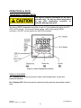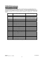
1
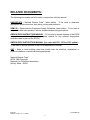
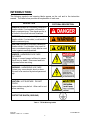
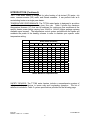
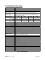
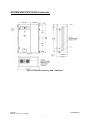
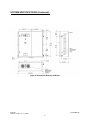
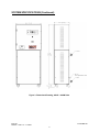
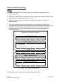
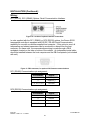
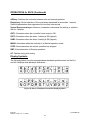
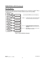
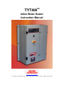
TM
TYTAN
Inline Water Heater
Instruction Manual
www.process-technology.com
7010 Lindsay Dr., Mentor, OH 44060 Phone: 440-974-1300 Fax: 440-974-9561 USA/CN: 800-621-1998
TABLE OF CONTENTS:
RELATED DOCUMENTS ............................................................................................... 3
INTRODUCTION............................................................................................................. 4
SYSTEM SPECIFICATIONS .......................................................................................... 6
MODEL NUMBER......................................................................................................... 10
MODEL NUMBER EXPLANATION......................................................................................................... 11
FACILITY REQUIREMENTS ........................................................................................ 13
WATER PLUMBING REQUIREMENTS.................................................................................................. 14
ELECTRICAL REQUIREMENTS ............................................................................................................ 14
INSTALLATION ............................................................................................................ 15
INSPECTION AND UNCRATING ........................................................................................................... 15
POSITIONING AND MOUNTING.................................................................................. 17
PLUMBING.............................................................................................................................................. 18
WIRING ................................................................................................................................................... 20
RC1, RC2 COMMUNICATIONS (OPTIONAL)........................................................................................ 22
RC3 COMMUNICATIONS (OPTIONAL) ................................................................................................. 23
RI REMOTE INTERFACE (OPTIONAL) ................................................................................................. 23
OPERATIONS .............................................................................................................. 25
CONTROL PANEL .................................................................................................................................. 25
TEMPERATURE CONTROLLER E5CN ................................................................................................. 26
PARAMETER SETTINGS E5CN......................................................................................................... 29
CHANGING SET POINT E5CN........................................................................................................... 30
HIGH ALARM E5CN ............................................................................................................................ 30
PID TUNING E5CN.............................................................................................................................. 31
TEMPERATURE CONTROLLER E5CK (RC OPTIONS) ....................................................................... 32
PARAMETER SETTINGS E5CK ......................................................................................................... 35
CHANGING SET POINT E5CK ........................................................................................................... 36
HIGH ALARM E5CK ............................................................................................................................ 37
PID TUNING E5CK.............................................................................................................................. 38
OVER TEMPERATURE CONTROLLER: FDC-L91................................................................................ 39
SYSTEM START UP ............................................................................................................................... 42
SYSTEM SHUT DOWN........................................................................................................................... 42
MAINTENANCE............................................................................................................ 43
WARRANTY ................................................................................................................. 44
M-45-02
Revision - Date: 01 – 11/16/07
TYTAN Manual
2
RELATED DOCUMENTS:
The following documents are to be used in conjunction with this manual:
ANSI/NFPA70 – National Electric Code→, latest edition. To be used to determine
appropriate electrical service, wire sizing, routing and protection.
SEMI S2 – Semiconductor Equipment Safety Guidelines, latest edition. To be used in
conjunction with safe operation, access and decommissioning procedures.
OMRON E5CN INSTRUCTION MANUAL – To be used to access features of the E5CN
temperature controller. (Secure appropriate manual for any optional temperature
controller used in place of the E5CN).
OMRON E5CK INSTRUCTION MANUAL (for units with RC1, RC2 or RC3 option) –
To be used to access features of the E5CK temperature controller.
ANY – State or local building codes that would cover the electrical, mechanical, or
physical installation of electrical heating equipment.
National Electric Code→
NFPA 1999 Copyright
National Fire Protection Association
Quincy, Mass. 02269
M-45-02
Revision - Date: 01 – 11/16/07
TYTAN Manual
3
INTRODUCTION:
The following symbols and warning labels appear on the unit and in the instruction
manual. The table below provides an explanation of each one.
DESCRIPTION
PICTORAL DESCRIPTION
DANGER indicates an imminently hazardous
situation which, if not avoided, will result in
death or serious injury. This signal word is to
be limited to the most extreme situations.
WARNING indicates a potentially hazardous
situation which, if not avoided, could result in
death or serious injury.
CAUTION indicates a potentially hazardous
situation which, if not avoided, may result in
minor or moderate injury. It may also be used
to alert against unsafe practices.
DANGER: HAZARDOUS VOLTAGE
ENCLOSED
Voltage or current hazard sufficient to cause
shock, burn or death. Disconnect and lock
out power before servicing.
WARNING: HAZARDOUS VOLTAGE
Contact may cause electric shock or burn.
This unit to be serviced by trained personnel
only.
CAUTION: HOT SURFACE. DO NOT
TOUCH
Heater column may be hot. Allow unit to cool
before servicing.
PROTECTIVE EARTH (GROUND)
Table 1: TYTAN Warning Labels
M-45-02
Revision - Date: 01 – 11/16/07
TYTAN Manual
4
INTRODUCTION (Continued):
The TYTAN water heater is designed for inline heating of de-ionized (DI) water, city
water, reverse-osmosis (RO) water, and filtered seawater. It can perform both as a
recirculating heater or a single-pass heater.
TEMPERATURE PERFORMANCE: The TYTAN water heater is designed to provide a
specified temperature increase at a given flow rate. Table 2 shows the maximum
temperature increase (∆T) that can be achieved for continuous flow conditions at the
specific heater power ratings varying from 24 kW to 144 kW (Higher wattage systems
available upon request). The temperature control system provided with the heater will
modulate the power to the heating columns in order to maintain your specific outlet
temperature setting.
Heater Power (Kilowatts)
Flow Rate
GPM
1
2
4
6
8
10
12
14
16
18
20
22
24
12
80.8
40.4
20.2
13.5
10.1
8.0
6.7
5.7
5.0
4.5
4.0
3.6
3.3
18
24
36
48
72
96
120
Maximum Theoretical Temperature Rise (°F)
121.2
60.6 80.8 121.2
30.3 40.4 60.6 80.8 121.1
20.2 26.9 40.4 53.8 80.8 107.7 134.6
15.1 20.2 30.3 40.4 60.6 80.8 101.0
12.1 16.1 24.2 32.3 48.4 64.6 80.8
10.1 13.4 20.2 26.9 40.4 53.8 67.3
8.6 11.5 17.3 23.0 34.6 46.1 57.7
7.5 10.1 15.1 20.2 30.3 40.4 50.5
6.7
8.9 13.4 17.9 26.9 35.9 44.8
6.0
8.0 12.1 16.1 24.2 32.3 40.4
5.5
7.3 11.0 14.6 22.0 29.3 36.7
5.0
6.7 10.1 13.4 20.2 26.9 33.6
144
121.2
96.9
80.8
69.2
60.6
53.8
48.4
44.0
40.4
Table 2: Maximum Temperature Rise
SAFETY DEVICES: The TYTAN water heaters include a comprehensive system of
safety controls and devices to insure safe and long-lasting operation. The list of
safeties is included in Table 3: system specifications provided on the following page.
M-45-02
Revision - Date: 01 – 11/16/07
TYTAN Manual
5
SYSTEM SPECIFICATIONS:
Product
TYTAN inline titanium water heater
Standards
UL, cUL standard
CE, SEMI S3 optional (-SC)
12kW – 144kW
Refer to model number label for the wattage of any specific unit
208V – 600V, 50/60Hz, 3 phase standard
(Some voltages available in single phase or with special construction,
consult factory for details)
Available Wattage Range
Available Voltages
Cabinet dimensions:
Width
Depth
Height
Weight
12kW – 48kW
28.5-in (75 cm)
13.5-in (34 cm)
36-in (91 cm)
145 lbs. (66 kg)
72kW
37.5-in (95 cm)
13.5-in (34 cm)
36-in (91 cm)
230 lbs. (104 kg)
28-in (71 cm)
17-in (43 cm)
63-in (160 cm)
300 lbs. (136 kg)
96kW – 144kW
Wetted surfaces:
Heating elements
Columns and plumbing
PRV Valve
CP2 titanium standard, (316SS optional [-S option])
CP2 titanium standard, (316SS optional [-S option])
PVDF
Operating temperatures:
Process inlet
Process outlet
Temperature accuracy
Ambient air temperature
Up to 194°F (90°C), depending upon operating conditions
+/- 1°F, depending upon operating conditions
86°F (30°C) maximum
Water pressure range
Minimum water flow rate:
12kW - 24kW
36kW – 48kW
72 kW
96kW
120kW
144kW
Standard Safety Devices:
Minimum 10 psi (69 kPa, 0.69 bar)
Maximum 100 psi (690 kPa, 6.9 bar)
0.5 gpm (2 lpm)
1.0 gpm (4 lpm)
1.5 gpm (6 lpm)
2.0 gpm (8 lpm)
2.5 gpm (10 lpm)
3.0 gpm (12 lpm)
EMO Pushbutton
Pressure Relief Valve (PRV), connected to inlet manifold
Electrically grounded heating chamber construction
Ground Fault Protection (GFP)
Safety Limit Control (SLC)
Bimetallic heater over temperature sensor(s)
Heater outlet overtemperature alarm
Solid state relay (SSR) overheat bimetallic sensor
Sensor failure detection
Control circuit fuse protection
Table 3: TYTAN Specifications
M-45-02
Revision - Date: 01 – 11/16/07
TYTAN Manual
6
SYSTEM SPECIFICATIONS (Continued):
Figure 1: Dimensional Drawing, 12kW – 48kW Units
M-45-02
Revision - Date: 01 – 11/16/07
TYTAN Manual
7
SYSTEM SPECIFICATIONS (Continued):
Figure 2: Dimensional Drawing, 72kW Unit
M-45-02
Revision - Date: 01 – 11/16/07
TYTAN Manual
8
SYSTEM SPECIFICATIONS (Continued):
Figure 3: Dimensional Drawing, 96kW – 144kW Units
M-45-02
Revision - Date: 01 – 11/16/07
TYTAN Manual
9
MODEL NUMBER:
Process Technology model numbers are designed to offer some description of the
heater construction, including features and options. The model number can be found on
the model/serial number label located on the front of the unit, near the bottom (see
figures 1-3).
Figure 4: Model/Serial Number Label
M-45-02
Revision - Date: 01 – 11/16/07
TYTAN Manual
10
Model Number (Continued):
Model Number Explanation:
Provided below is an example of a typical model number along with an explanation of
each part. This key will help you understand your model number.
Model number example:
TY-072-480-3-SC-RI
c
d
e
f
g
c
Heater Series. The beginning of each model number will designate the product
line. In this case, the TYTAN inline titanium water heater.
d
Heater Wattage. The numerical portion of the model number will always begin
with the wattage of your heater. The table provided below identifies the standard
available wattage ratings and the number of heater columns needed to provide
that amount of Wattage.
HEATER
MODEL
NUMBER
HEATER
WATTAGE
(W)
NUMBER
OF HEATER
COLUMNS
WATTAGE
PER
HEATING
COLUMN
(W)
HEATER
MODEL
NUMBER
HEATER
WATTAGE
(W)
NUMBER
OF HEATER
COLUMNS
WATTAGE
PER
HEATING
COLUMN
(W)
012
12,000
1
12,000
072
72,000
3
24,000
018
18,000
1
18,000
096
96,000
4
24,000
024
24,000
1
24,000
120
120,000
5
24,000
036
36,000
2
18,000
144
144,000
6
24,000
048
48,000
2
24,000
Table 4: Wattage and Column Table
M-45-02
Revision - Date: 01 – 11/16/07
TYTAN Manual
11
Model Number Explanation (continued):
TY-072-480-3-SC-RI
c
d
e
f
g
e
Heater Voltage. The first character following the heater Wattage will describe
the rated Voltage of the heater.
f
Heater Phase. This character will specify if this unit is designed for single
phase (-1) or three phase (-3) power.
g
Options. The remaining characters will specify any options included in this
system. Many of these options can be combined on a single Tytan water heater.
Only a few options are mutually exclusive.
Model Number
Option
-CB
Include circuit breaker with disconnect switch.
-SC
Built to SEMI S3 standards, CE compliant version
(Includes –CB option)
-PLC
PLC temperature controller, in place of the standard PID
controller
-RI
Remote interface. This will allow the user to start, stop,
reset the unit and monitor the safety circuit remotely.
-RC1
RS485 communications interface with the Omron PID
temperature controller (requires optional E5CK
controller)
-RC2
RS232 communications interface with the Omron PID
temperature controller (requires optional E5CK
controller)
-RC3
4-20mA process
controller)
output
(requires
optional
E5CK
-S
Wetted surfaces to be passivated 316 stainless steel.
-X
Special option, consult factory
-##
Special construction design, consult factory for details
Table 5: TYTAN Options
M-45-02
Revision - Date: 01 – 11/16/07
TYTAN Manual
12
FACILITY REQUIREMENTS:
Before installing the TYTAN inline water heater confirm the facility requirements listed
below.
Space Requirements:
The TYTAN inline water heater is constructed in a wall-mounted or freestanding
enclosure. The dimensions of this enclosure are based upon the wattage of the unit.
This enclosure includes the common framework for the heating column(s) as well as the
electrical components.
The enclosure requires adequate ventilation. Locate equipment so that ventilation
provisions on the bottom and sides of the enclosure are not obstructed. The ventilation
fan exhausts air through these openings which prevents overheating of the interior. Be
sure to provide adequate clearance for normal operation and maintenance of this
heater.
The standard dimensions of the various models are shown in Table 3 (see appendix for
custom made units). Allow additional space on all sides of the unit for the control
ventilation and service access. (all dimensions are in inches).
Figure 5: Clearance Dimensions for Wall-Mounted Units (72kW Model Shown)
M-45-02
Revision - Date: 01 – 11/16/07
TYTAN Manual
13
Facility Requirements (continued):
Water Plumbing Requirements:
The customer supplied inlet and outlet plumbing must be rated to withstand
temperatures up to 275°F (135°C) at pressures up to 100 psi (6.9 Bar).
The wall-mounted TYTAN units are supplied standard with 1-inch MNPT threaded pipe
connections for the plumbing inlet and outlet. These connections extend from the right
side of the unit, with the inlet near the bottom and the outlet near the top (see figures 12). There is also a ½-inch FNPT threaded pipe connection for the PRV valve on the
right side of the enclosure which must be plumbed to a non-pressurized drain. Special
plumbing connections are available as an option. Refer to your specific unit for any
special connections.
The free-standing TYTAN units are supplied standard with 2-inch MNPT threaded pipe
connections for the plumbing inlet and outlet. These connections extend from the back
of the unit, with the inlet near the bottom and the outlet near the top (see figure 3).
There is also a ½-inch FNPT threaded pipe connection for the PRV valve on the back of
the enclosure, which must be plumbed to a non-pressurized drain. Special plumbing
connections are available as an option. Refer to your specific unit for any special
connections.
Do not reverse the plumbing connections of
this unit.
Failure to observe the correct
plumbing orientation will result in hightemperature conditions and heater failure.
Electrical Requirements:
NOTE: Ensure electrical power fusing and disconnects meet local jurisdictional
requirements. Fuse ratings noted in this document are for reference only.
Ensure external electrical components comply with local requirements before
operating this unit.
Reference the model/ serial number label to identify the electrical power requirements of
this unit (see figure 4). Verify that the incoming electrical service is rated and fused for
the required amperage draw.
Do not exceed the rated voltage. Irreparable
damage to the heating column or control
circuitry may result.
M-45-02
Revision - Date: 01 – 11/16/07
TYTAN Manual
14
INSTALLATION:
NOTE: The mounting and installation of this unit should only be performed by
qualified personnel.
Inspection and Uncrating:
The wall-mounted TYTAN units are shipped in a horizontal position. The free-standing
TYTAN units are shipped in a vertical position.
Due to the weight of the unit, DO NOT
ATTEMPT to move or lift the unit without the
appropriate material handling equipment.
1) Inspect the shipping crate for evidence of damage. If any damage is detected,
contact the carrier immediately.
2) Inspect the shock sensors located on the outside of the crate. The shock sensors
will indicate if the unit experienced rough handling. If the sensors indicate that the
unit has experienced rough handling, contact the carrier immediately. If the shock
sensor on the outside of the crate is missing, there is also a shock sensor located on
the inside of the crate.
Figure 6: Shockwatch Sensor
M-45-02
Revision - Date: 01 – 11/16/07
TYTAN Manual
15
INSTALLATION (Continued):
Uncrating the wall-mounted units:
3) Remove the top of the crate.
4) Remove any protective packaging material and any other materials that may have
been packed in the crate with the enclosure.
5) Remove any braces used to hold the unit in place during shipping.
6) Using a hoist or other suitable lifting device, lift the unit from the mounting holes on
the side flanges and remove from the crate. Do NOT lift the unit by holding the
plumbing connections or (if present) the disconnect handle.
Uncrating the free-standing units:
3) Remove the front of the crate.
4) Remove any protective packaging material and any other materials that may have
been packed in the crate with the enclosure.
5) Remove any braces used to hold the unit in place during shipping.
6) Using a hoist or other suitable lifting device, lift the unit from underneath and remove
from the crate. Do NOT lift the unit by holding the plumbing connections or (if
present) the disconnect handle.
Do not tip the unit beyond 10° from vertical.
Serious personal injury or equipment damage
may result.
M-45-02
Revision - Date: 01 – 11/16/07
TYTAN Manual
16
INSTALLATION (Continued):
Positioning and Mounting:
Wall-mounted units:
The wall-mounted TYTAN units must be anchored to a support structure that can
support at least 275-pounds (125 kg). We recommend that the mounting bolts are no
smaller than a 3/8-16 thread.
We recommend that the unit is mounted such that the temperature controller is no more
than 78-inches (2 meters) above the floor level (see figure 5).
Free-standing units:
Move the unit into position by lifting the unit from underneath using a fork truck or other
suitable handling equipment. Position the equipment to avoid damaging the cooling
fans located on the bottom of the unit.
The castors should not be used to move the
unit over long distances or on uneven surfaces.
They are intended to facilitate small
adjustments to the position of the unit at its
place of operation. Move the unit slowly, as
there is no means of slowing or stopping the
unit. Ensure that there are sufficient personnel
to move the unit safely. Failure to follow these
instructions can result in serious personal
injury and/or damage to the unit.
Place the unit on a hard, level surface. Ensure the unit is secured so as not to roll as
the casters are unlocked. Once the unit is in position, lock the four castors.
Ensure the unit is on a smooth, level surface
and there are sufficient personnel to hold the
unit in place. As the leveling feet are retracted
and the unit rests on the castors unexpected
movement may result. Failure to properly
secure the unit may result in serious personal
injury and/or damage to equipment.
M-45-02
Revision - Date: 01 – 11/16/07
TYTAN Manual
17
INSTALLATION (Continued):
Plumbing:
The plumbing installation of this unit should only be performed by qualified technicians.
Verify that the water supply is shut off, and any
necessary lockout/tagout devices are properly
installed.
The customer supplied inlet and outlet plumbing must be rated for temperatures up to
275°F (135°C) at pressures up to 100 psi (6.9 Bar).
On all TYTAN units, the lower plumbing connection will always be the inlet, and the
upper plumbing connections will always by the outlet. The inlet plumbing to the unit
must include the means to drain the unit, which may be necessary in the case of
replacing the heating column or other parts.
Do not reverse the plumbing connections of
this unit.
Failure to observe the correct
plumbing orientation will result in hightemperature conditions and heater failure.
M-45-02
Revision - Date: 01 – 11/16/07
TYTAN Manual
18
INSTALLATION (Continued):
Plumbing (Continued):
When tightening all connections on this unit, be sure to support the TYTAN heater
connection to prevent excessive torque or strain from damaging the internal plumbing of
the unit.
Figure 7: Tytan Heater Connection Support
Failure to properly support the TYTAN
plumbing connections during tightening will
result in equipment damage and internal water
leaks. Such damage is not covered under the
product warranty.
Inlet/Outlet Plumbing Connections:
1) Remove the protective plastic caps from inlet and outlet plumbing.
2) Test fit the piping to insure proper length.
3) Support the TYTAN pipe fittings to avoid any damage during tightening.
4) Tighten the connections as required. Take care not to over-tighten.
5) Establish water flow through the unit. Inspect the plumbing for leaks.
M-45-02
Revision - Date: 01 – 11/16/07
TYTAN Manual
19
INSTALLATION (Continued):
Plumbing (Continued):
PRV Plumbing Connection:
1) Test fit the drain pipe to insure proper length. The PRV must be connected to a nonpressurized drain.
2) Support the TYTAN PRV fitting to avoid any damage during tightening.
3) Tighten the connection as required. Take care not to over-tighten.
Wiring:
The wiring of this unit should only be performed by qualified technicians.
Verify that the electrical power supply is shut
off, and any necessary lockout/tagout devices
are properly installed.
Power Connections:
TYTAN units are designed to operate on 4 wire electrical power supplies (3 power
wires, 1 ground wire). All electrical connections should conform to local electrical codes
and/or NFPA 70/79.
There is no pilot hole for incoming power supply conduit. This hole will have to be cut in
the top of the enclosure during installation.
Figure 8: Recommended location for power supply conduit (72kW unit shown)
1) Check the model/serial number on the front of the unit for power requirements.
Do not exceed the rated voltage. Irreparable
damage to the heating column or control
circuitry may result.
M-45-02
Revision - Date: 01 – 11/16/07
TYTAN Manual
20
INSTALLATION (Continued):
Wiring:
2) Remove front cover of the control side of the cabinet by loosening the cover
mounting screws.
3) Cut a hole in the top of the enclosure for the incoming power supply to allow for the
power supply to enter the top of the enclosure.
4) Fuse the incoming line for the rated amperage using an approved electrical
disconnect box.
5) Connect the leads from the incoming power line to the appropriate terminals
(reference the Electrical Schematic) making sure not to disturb existing wiring. Use
care that no loose strands of wire are exposed out of the terminal connection.
Torque all wires to the specified ratings located on the wiring diagrams and
component labels.
TORQUE SPECIFICATIONS
CIRCUIT BREAKER
DISTRIBUTION BLOCK
PRIMARY:
SECONDARY:
SECONDARY:
POWER FUSES
SAFETY CONTACTOR
SOLID STATE RELAYS
INPUT :
OUTPUT :
Figure 9: Torque Specifications Label
6) Grounding is done internally from the Incoming Power Strip.
M-45-02
Revision - Date: 01 – 11/16/07
TYTAN Manual
21
INSTALLATION (Continued):
Wiring:
RC1 (RS232), RC2 (RS485) Options: Serial Communication Interface:
Figure 10: Location of optional interface connections
In units supplied with the RC1 (RS485) or RC2 (RS232) options, the Omron E5CK
temperature controller is equipped with RS-232 / RS-485 Serial Communication
capability for use with a customer-supplied host computer. If this option is used, all
temperature and related parameters can be monitored or altered from the host
computer. On these units, the communications wiring is made through a DB-9
receptacle located on the side or bottom of the cabinet. An independent serial cable
should be installed between the host computer and the DB-9 receptacle (not included
with unit).
Figure 11: DB9 connector, for optional -RC# remote communications
RC1 (RS485) Communications pin assignment:
Pin Number
Signal
2
Positive (+)
3
Negative (-)
1, 4, 5, 6, 7, 8, 9
Not used
RC2 (RS232) Communications pin assignment:
Pin Number
Signal
2
Send
3
Receive
5
Signal Ground
1, 4, 6, 7, 8, 9
Not used
M-45-02
Revision - Date: 01 – 11/16/07
TYTAN Manual
22
INSTALLATION (Continued):
Wiring:
RC3 (4-20 mA) Option: Process Output:
Units provided with the RC3 option will include a 4-pin connector plug, for wiring of the
4-20 mA process output. This process output will allow the user to record the outlet
temperature of the Tytan heater from a remote device. This signal is an output only.
Figure 12: 4-pin connector plug, for optional –RC3 process output
RC3 option process output pin assignment:
Pin Number
Signal
1
Positive (+)
2
Negative (-)
3, 4
Not used
RI Option: Remote Interface:
Units provided with the RI option will include a 16-pin connector plug which will allow
remote operation of the Tytan inline water heater. The remote interface will allow remote
operation of heater start/stop, remote EMO trip and remote monitoring of heater
enabled and the status of the alarm system. Some of the remote interface inputs have
been jumped at the factory, to allow for heater operation with the remote interface cable
disconnected. These jumpers are located in the electrical side of the heater cabinet,
and are marked by a red tag. If the customer wants to use the remote interface, these
red tag jumpers must be removed.
If the unit was provided with a custom remote interface (-RI# at the end of the model
number), then refer to the electrical prints (provided with the unit) for your specific
signals and pin-out assignments.
Figure 13: 16-pin connector plug, for optional -RI, -RI# remote interface
M-45-02
Revision - Date: 01 – 11/16/07
TYTAN Manual
23
INSTALLATION (Continued):
Wiring:
RC3 option process output pin assignment:
Pin
Number
1, 2
Signal
EMO
Signal type
Description
The customer supplied remote controller can trip
an EMO condition on the unit by opening contacts
across these two pins.
Input,
This is one of the signals that has been bypassed
at the factory. In order to use this remote EMO
feature, the red tag jumper must be removed.
Dry contacts
The EMO condition must be reset at the unit.
3, 4
Start/Stop
The customer supplied remote controller can start
heater operation by closing the contacts across
these pins, when the controller is in REMOTE
mode only.
Input,
This is one of the signals that has been bypassed
at the factory. In order to use this remote EMO
feature, the red tag jumper must be removed.
Dry contacts
Open contacts will stop heater operation.
9, 10
System Fault
This output will apply open contacts across these
pins when any alarm condition has been tripped.
Once the alarm condition has been corrected, the
unit will require a manual reset at the unit. The
unit can not be reset remotely.
Output,
Dry Contacts
Open contacts indicate all of the safety devices
are in normal operating mode.
11, 12
Heater
Enabled
This output will apply closed contacts across
these pins when power is applied to the unit, there
is not EMO condition and the heater selector
switch is set to ON.
Output,
Dry contacts
Open contacts indicate the EMO has been tripped
or the unit has been stopped or shut down.
M-45-02
Revision - Date: 01 – 11/16/07
TYTAN Manual
24
OPERATIONS:
Control Panel:
Figure 14: Temperature Controller and Control Panel.
The TYTAN Heating System incorporates a self-tuning, PID microprocessor based,
digital temperature controller with a set high temperature alarm. The PID feature
enhances the controller's ability to reach and maintain a constant process temperature.
The self-tuning feature enables the controller to measure the process characteristics
and indicate desired values, which can be displayed on LED displays.
The following sections provide a description and instructions for two available
temperature controllers:
1. The Omron E5CN Controller. This is the temperature controller used on standard
Tytan heaters. For a complete user guide, visit the Omron website; www.omron.com.
2. The Omron E5CK Controller. This is the temperature controller used on Tytan
heaters with the RC1, RC2 or RC3 options. For a complete user guide, visit the
Omron website; www.omron.com
These two temperature controllers program differently, and have slightly different control
settings. Be sure to refer to the correct temperature controller section when
programming your unit.
M-45-02
Revision - Date: 01 – 11/16/07
TYTAN Manual
25
OPERATIONS (Continued):
Temperature Controller E5CN:
This section contains information for the E5CN
controller only. Do not use these instructions
for any other temperature controller, or
controller damage may result.
Figure 15: Omron Temperature Controller
DISPLAY FEATURES:
No. 1 display (PV): Shows the process value (outlet temperature), modes and
parameter symbols.
No. 2 display (SV): Shows set points, parameter operation read value, or the variable
input value.
Level key: Switches the controller between auto and manual operation.
Mode key: Press this key to change parameters within a setting level.
Up and Down arrow keys: Advances, increases or decreases the setting or values in
the No. 2 display. Holding these keys down will speed up the rate of change.
M-45-02
Revision - Date: 01 – 11/16/07
TYTAN Manual
26
OPERATIONS for E5CN (Continued):
Display Symbols:
Operation Indicators:
ALM1:
Illuminates when the alarm 1 setting is ON (tripped) (120°C).
ALM2:
Illuminates when the alarm 2 setting is ON (tripped) (110°C).
ALM3:
Not available on this controller.
HA:
Not available on this controller.
OUT1:
Illuminates when the control output 1 is ON.
OUT2:
Illuminates when control output 2 is ON (Not used).
STOP:
Illuminates when the control operation has stopped.
CMW:
Illuminates when communications wiring is enabled.
:
MANU:
Illuminates when setting change protection is ON.
Illuminates when the controller is in Manual operation mode.
The following tables show the correspondence between symbols shown on the No.1
and No.2 displays and alphabetic characters.
Figure 16: Omron Temperature Controller Display Symbols
M-45-02
Revision - Date: 01 – 11/16/07
TYTAN Manual
27
OPERATIONS for E5CN (Continued):
Using the keys:
This section describes the basic functions of the front panel keys.
Level Key: Press this key to move between setting levels. The setting level is
selected in the following order: operation level: adjustment level, initial setting
level, communications setting level.
Mode Key: Press this key to change parameters within a setting level. The
parameters can be reversed by holding down the key (moving one per second in
reverse order).
Up Key: Each press of this key increments the value displayed on the No. 2
display or
advances the setting. Holding the key down speeds up the incrementation.
Down Key: Each press of this key decrements values displayed on the No. 2
display or reverses the setting. Holding the key down speeds up the
incrementation.
Selecting Menu Levels:
The following section describes how to access the various menu levels in the Omron
controller.
Operations Level:
Press the mode key.
Adjustment Level:
Press and hold the level key for at least 1 second.
Initial Setting Level:
Press and hold the level key for at least 3 seconds.
Protect Level:
Press and hold the level key and the mode key
simultaneously for at least 3 seconds.
Advanced Function Setting Level: (Note: in order to access this level, the ICPt setting
in the protect level must be set at 0) Index through the
initial setting level and adjust the AmoV setting to “-169”.
M-45-02
Revision - Date: 01 – 11/16/07
TYTAN Manual
28
OPERATIONS for E5CN (Continued):
Mode Parameter Settings:
The Omron E5CN temperature controller has been programmed prior to shipment, so
no additional programming is normally necessary. The table below shows the various
controller settings for this unit when properly configured to operate the TYTAN inline
heater. Some internal menus have been factory programmed and subsequently locked.
Those menus are not listed.
The selections in bold indicate settings that have been changed from the original
factory default for operation with the TYTAN inline heater.
Level
Operations
Level
Adjustment
Level
Parameter
R-S
AL-1
AL-2
LAdJ
At
INS
P
I
D
SPRt
OL-H
OL-L
Description
Run – Stop selection
Alarm value 1
Alarm value 2
Adjustment level
Autotune execute
Temperature input shift
Proportion band
Integral time
Derived time
SP ramp set value
MV upper limit
MV lower limit
Setting
RUN
120°C
110°C
OFF
0.0
80**
233**
40**
OFF
100.0
0.0
** The P, I and D values may change following the execution of Auto-tune.
Table 6: Omron E5CN Parameters
M-45-02
Revision - Date: 01 – 11/16/07
TYTAN Manual
29
OPERATIONS for E5CN (Continued):
Changing Primary Set Point:
1. The process Set Point can be changed in the normal display mode.
2. Press the up and down arrow keys to select the desired setting.
After changing the process set point (SP-0) on the Omron controller, you must
manually adjust the SP2 setting on the Future Design over-temperature control.
See OPERATIONS Over-Temperature Controller FDC-L91 section.
High Alarm:
The Omron E5CN temperature controller incorporates an independent high-temperature
alarm. Alarm 1 (AL-1) prevents heater operation above a preset maximum temperature
that may harm the process and potentially the tank material. If the process temperature
exceeds the preset high alarm value, the heater will be disengaged and the audibly
alarm will sound. The temperature controller will activate once the process temperature
exceeds the set point by the preset value. The factory setting of this alarm temperature
is 248°F (120°C).
The high alarm value can be adjusted to a lower setting through the operations level.
1. Press the mode key
to enter the operations level.
2. Press the mode key
to index through the operations level to the AL-1 setting.
3. Press the up or down key to adjust AL-1 to the desired setting.
4. Press the mode key
to index through the operations level to the AL-2 setting.
5. The AL-2 setting is normally set at 10°C below AL-1. Press the up and down keys to
adjust AL-2 to the desired setting.
6. Press and hold the level key for a minimum of three seconds to return to the normal
display.
M-45-02
Revision - Date: 01 – 11/16/07
TYTAN Manual
30
OPERATIONS for E5CN (Continued):
PID Tuning:
The Omron E5CN temperature controller incorporates the capability of automatically
tuning the PID parameters (Auto-Tuning) to fit the characteristics of the process. The
optimum PID parameters are automatically set by forcibly changing the Manipulated
Variable (MV) to calculate the characteristics (limit cycle method) of the control target.
Depending on the auto-tune level selected, AT-1 or AT-2, the controller will run this test
at either 40% or 100% of the actual Process Set Point. When the auto tuning is
complete, the appropriate PID tuning parameters will be automatically installed into the
non-volatile memory of the temperature controller.
1. Turn on water supply and set the desired water flow.
2. Set the Process Temperature Set point to the desired value.
(See OPERATIONS; Changing Primary Set point,).
3. Press and hold the level key for a minimum of one second to enter the
adjustment level.
4. Press the mode key to index through the adjustment level to get to the At
settting.
5. Press the up or down arrow key to adjust the At value to oN.
6. Press and hold the level key for at least 3 seconds to return to the normal
display.
7. Turn the ENABLE HEATER switch past the ON position to the RESET position,
then release the switch, which will move to the ON position. If all criteria for the
various safety devices have been met, the heater will begin to heat.
8. When the process is complete, the appropriate PID tuning parameters will be
installed and retained in the non-volatile memory.
M-45-02
Revision - Date: 01 – 11/16/07
TYTAN Manual
31
OPERATIONS for E5CK:
Temperature Controller E5CK:
This section contains information for the E5CK
controller only. Do not use these instructions
for any other temperature controller, or
controller damage may result.
The Omron E5CK temperature controller is used on Tytan heaters that utilize the RC1,
RC2 or RC3 options. For units with these options, refer to this section (E5CK
controller). Do NOT use the section for the E5CN controller
Figure 17: Omron Temperature Controller
DISPLAY FEATURES:
No. 1 display (PV): Shows the process value (outlet temperature), modes and
parameter symbols.
No. 2 display (SV): Shows set points, parameter setting and the manipulated variable
heat.
M-45-02
Revision - Date: 01 – 11/16/07
TYTAN Manual
32
OPERATIONS for E5CK (Continued):
A/M key: Switches the controller between auto and manual operation.
Display key: Allows selection of the mode when depressed for more than 1 second.
Switches parameters when depressed for less than one second.
Up and Down arrow keys: Advances, increases or decreases the setting or values in
the No. 2 display.
OUT1: Illuminates when the controller’s heat output is ON.
OUT2: Illuminates when the alarm 1 setting is ON (tripped).
SUB1: Illuminates when the alarm 2 setting is ON (tripped).
MANU: Illuminates when the controller is in Manual operation mode.
STOP: Illuminates when the control operation has stopped.
RMT: Illuminates when in Remote operation.
AT: Flashes during auto-tuning.
Display Symbols:
The following tables show the correspondence between symbols shown on the No.1
and No.2 displays and alphabetic characters.
Figure 18: Omron Temperature Controller Display Symbols
M-45-02
Revision - Date: 01 – 11/16/07
TYTAN Manual
33
OPERATIONS for E5CK (Continued):
Selecting Modes:
The modes are selected by pressing the Display Key for one second or greater. The up
and down arrow keys allow the movement between modes in the top display.
Figure 19: Omron E5CK Menu Navigation
M-45-02
Revision - Date: 01 – 11/16/07
TYTAN Manual
34
OPERATIONS for E5CK (Continued):
Mode Parameter Settings:
The Omron E5CK temperature controller has been programmed prior to shipment, so
no additional programming is normally necessary. The table below shows the various
controller settings for this unit when properly configured to operate the TYTAN inline
heater. Some internal menus have been factory programmed and subsequently locked.
Those menus are not listed.
The selections in bold indicate settings that have been changed from the original
factory default for operation with the TYTAN inline heater.
Mode
Parameter
Level 0
SP-n
O
C-o
Level 1
r–S
At
SP-0
AL–1
AL–2
P
i
D
C-SC
C-db
Of-R
HYS
CHYS
CP
C-CP
SPrU
Description
Set point during ramp
Manipulated variable (MV) monitor for
heat
Manipulated variable (MV) monitor for
cool
Run/Stop
Auto Tune (AT) execute/cancel
Set point 0 (Process Set point)
High Alarm
Temperature Deviation
Proportional Band
Integral Time
Derivative Time
Cooling coefficient
Dead band
Manual reset value
Hysteresis (heat)
Hysteresis (cool)
Heating control period/cycle time
Cooling control period/cycle time
Set Point ramp time unit
Setting
NP
0
NP
Run
o-FF
Determined by Operator
120°C (248°F)
10°C (15°F)
10.0 (default)**
233 (default)**
40 (default)**
1sec
M, minutes
** The P, I and D values may change following the execution of Auto-tune.
Table 7: Omron E5CK Parameters
M-45-02
Revision - Date: 01 – 11/16/07
TYTAN Manual
35
OPERATIONS for E5CK (Continued):
Changing Primary Set Point:
3. The process Set Point can be changed in the level 1 mode menu.
4. Press the Display Key
for a minimum of one second to enter the level select
mode.
5. Press the up or down arrow key to select the desired level. (Level 1 for process
set point adjustment).
6. Press the Display Key
for a minimum of one second to enter the selected
level mode menu.
7. Press the Display Key
for less than one second to cycle through the selected
level mode menu until (SP-0) is shown on the upper display.
8. Press the up or down arrow key to adjust the (SP-0) value to the desired point.
9. Press the Display Key
for a minimum of one second to once again enter the
level select mode.
10. Press the up or down arrow key to select the desired level. (Level 0 for normal
control operation).
After changing the process set point (SP-0) on the Omron controller, you must
manually adjust the SP2 setting on the Future Design over-temperature control.
( See OPERATIONS Over-Temperature Controller FDC-L91 section.
M-45-02
Revision - Date: 01 – 11/16/07
TYTAN Manual
36
OPERATIONS for E5CK (Continued):
High Alarm:
The Digital Temperature Controller incorporates an independent alarm. The High
Process Temperature Alarm (AL-1) prevents heater operation above a preset maximum
temperature that may harm the process and potentially the tank material. If the process
temperature exceeds the preset high alarm value, the heater will be disengaged. The
temperature controller will activate once the process temperature exceeds the set point
by the preset value. The factory setting of this alarm temperature is 248°F (120°C).
The high alarm value can be adjusted to a lower setting through mode Level 1.
7. The process Set Point can be changed in the level 1 mode menu.
8. Press the Display Key
for a minimum of one second to enter the level select
mode.
9. Press the up or down arrow key to select the desired level. (Level 1 for high process
temperature alarm adjustment).
10. Press the Display Key
for a minimum of one second to enter the selected level
mode menu.
11. Press the Display Key
for less than one second to cycle through the selected
level mode menu until (AL-1) is shown on the upper display.
12. Press the up or down arrow key to adjust the (AL-1) value to the desired point.
13. Press the Display Key
for a minimum of one second to once again enter the
level select mode.
14. Press the up or down arrow key to select the desired level. (Level 0 for normal
control operation).
M-45-02
Revision - Date: 01 – 11/16/07
TYTAN Manual
37
OPERATIONS for E5CK (Continued):
PID Tuning:
The Digital Temperature Controller incorporates the capability of automatically tuning
the PID parameters (Auto-Tuning) to fit the characteristics of the process. The optimum
PID parameters are automatically set by forcibly changing the Manipulated Variable
(MV) to calculate the characteristics (limit cycle method) of the control target.
Depending on the auto-tune level selected, AT-1 or AT-2, the controller will run this test
at either 40% or 100% of the actual Process Set Point. When the auto tuning is
complete, the appropriate PID tuning parameters will be automatically installed into the
non-volatile memory of the temperature controller.
The PID Tuning Process can be started by adjusting the (At) parameter.
9. Turn on water supply and set the desired water flow.
10. Set the Process Temperature Set point to the desired value.
(See OPERATIONS; Changing Primary Set point,).
11. Press the Display Key
mode.
for a minimum of one second to enter the level select
12. Press the up or down arrow key to select the desired level. (Level 1 for Auto
Tune adjustment).
13. Press the Display Key
level mode menu.
for a minimum of one second to enter the selected
14. Press the Display Key
for less than one second to cycle through the selected
level mode menu until (At) is shown on the upper display.
15. Press the up or down arrow key to adjust the (At) value to the desired setting of
(AT-2).
16. Press the Display Key
level select mode.
for a minimum of one second to once again enter the
17. Press the up or down arrow key to select the desired level. (Level 0 for normal
control operation). The “AT” LED will flash during the Auto-Tune cycle.
18. Turn the ENABLE HEATER switch past the ON position to the RESET position,
then release the switch, which will move to the ON position. If all criteria for the
various safety devices have been met, the heater will begin to heat.
19. When the process is complete, the “AT” LED will stop flashing. The appropriate
PID tuning parameters are now installed and retained in the non-volatile memory.
M-45-02
Revision - Date: 01 – 11/16/07
TYTAN Manual
38
OPERATIONS (Continued):
Over-Temperature Controller FDC-L91:
1. This over-temperature controller is located inside the electrical portion of the Tytan
heater. It uses a separate temperature sensor to monitor the temperature on the
surface of the heating elements.
2. This controller has two discreet set points:
SP2: This is the over-temperature cutoff setting, which is set for 18°F
(10°C) ABOVE the primary set point on the Process temperature
controller.
HSP1: This is an element high-temperature alarm setting, which is factory
set at 248°F (120°C). Do not adjust this setting.
Figure 20: Futuredesign Over Temperature Controller
M-45-02
Revision - Date: 01 – 11/16/07
TYTAN Manual
39
OPERATIONS (Continued):
Mode Parameter Settings:
The Futuredesign FDC-L91 temperature controller has been programmed prior to
shipment, so no programming will be necessary. The table below shows the various
controller settings for this unit when properly configured to operate the TYTAN inline
heater.
Parameter
Description
Default Setting
HSP1
LSP1
SP2
Hi Limit Set Point
Low Limit Set Point
Set Point 2 value, for Output 2
INPT
UNIT
RESO
IN.LO
IN.HI
SHlF
FILT
OUT1
O1.HY
HSP.L
HSP.H
LSP.L
LSP.H
OUT2
ADDR
BAUD
PARI
AL.FN
AL.MD
AL.HY
AL.FT
EIFN
DISP
Input Type Selection
Process Unit
Display Resolution
Low Scale for Linear Input
High Scale for Linear Input
PV Shift (offset) Value
PV Filter Time Constant
Output 1 Function
Output Hysteresis Value
Lower Limit of HSP1
Upper Limit of HSP1
Lower Limit of LSP1
Upper Limit of LSP1
Output 2 Function
Address Assgnmnt of Digital Com
Baud Rate of Digital Com
Parity Bit of Digital Com
Alarm Function
Alarm Mode
Alarm Hysteresis
Alarm Failure Transfer
Event Input Function
Normal Display Format
120 C / 248 F
82 C / 180 F
10 C / 18 F above”SP0” of the
E5CN Temperature Controller
J_tC
C/F
NodP
0
100 C / 212 F
0
2
HI
0.1
0
150 C / 302 F
0
120 C / 248 F
ALA
Not used
Not Used
Not Used
PYLA
Norm
0.1
ON
0
PV
Table 8: Future Design L91 Parameters
M-45-02
Revision - Date: 01 – 11/16/07
TYTAN Manual
40
OPERATIONS (Continued):
Programming FDC-L91:
Every time the primary set point of the main controller E5CN is modified, the SP2
setting on the over-temperature controller FDC-L91 must be changed manually.
To Change the SP2 set point on the FDC-L91 over-temperature controller, follow the
following procedure:
Do not change any of the other settings in this controller.
1. Turn the “Enable Heater” switch to the Off position. Leave the “Control Power”
switch in the On position.
2. Open the door to the control-portion of the unit.
When the enclosure door is open, be careful
not to touch the electrified components inside.
To avoid shock hazard, qualified personnel
should only perform this procedure.
Note: If the “Lock” LED is lit on the face of the Over-temperature Controller, press
the (
) key for 4 seconds to clear “lock” feature of the FDC-L91, enabling up /
down key function.
3. Identify the over-temperature controller, tagged 1SLC.
4. Press the Index key (
highlighted.
) to advance through the menu until “SP2” is
5. Using the up and down arrow keys, adjust the SP2 value until it is 18°F (10°C)
higher than the set point on the temperature controller.
Note: Do not change any other settings on this controller.
6. Close the door to the control portion of the enclosure.
M-45-02
Revision - Date: 01 – 11/16/07
TYTAN Manual
41
OPERATIONS (Continued):
System Start-Up:
1) Turn on water at its supply source. Allow water to flow for several minutes to insure
that all entrapped air has been purged from the heating column(s).
2) Stop water flow at point of use location and check all plumbing connections and
water heater for leaks. Repair any water leaks if applicable.
3) Enable the power at the MAIN SERVICE DISCONNECT (provided by customer).
4) Ensure that the disconnect handle on the front of the unit (if provided) is ON and the
EMO button on the front panel is not depressed.
5) Turn the CONTROL POWER toggle switch to the ON position. At this time the
temperature controller and all optional displays will come on.
Note: Temperature controller set point should be set to "0" at this time to
prevent accidental heater engagement during calibration procedures. Reference
temperature controller section if required.
6) Adjust the setpoint of the temperature controller to the desired value.
7) Turn the ENABLE HEATER switch past the ON position to the RESET position, then
release the switch, which will move to the ON position. If all criteria for the various
safety devices have been met, the heater will begin to heat.
System Shut-Down:
1) Turn the ENABLE HEATER switch from the ON position to the OFF position.
Continue water flow through the heater until the outlet temperature display indicates
95°F (35°C) or less.
2) Turn the CONTROL POWER toggle switch to OFF.
3) Turn off the MAIN SERVICE DISCONNECT to the unit (provided by customer).
4) Stop water flow through the unit. If the shut down will be for an extended period,
open the customer supplied drain located near the inlet plumbing connection to drain
the water from the unit. Once the unit is drained, dry the unit by blowing inert gas
(N2 or CDA) through the piping system.
M-45-02
Revision - Date: 01 – 11/16/07
TYTAN Manual
42
MAINTENANCE:
The Tytan water heater requires only a routine inspection every 6 months to check the
operation of the various operation and safety devices. Many of these devices require
the control system to remain operational during inspection, while others may be
checked while the unit is completely powered down.
Note: Several maintenance tasks can be completed simultaneously while the
cabinet access covers are open and lockout/tagout procedures are in place.
The maintenance procedures for this unit must be performed by qualified technicians.
Normal maintenance of TYTAN™ DI Water Heaters consists of the following:
1) Disinfect the water heater along with the rest of the plumbing system on a regular
basis if continuous sanitizing such as ozone injection is not employed.
2) Inspect the temperature sensors every 24 months, replace as needed.
3) Replace the heater control relays and fan after approximately 24-30 months of use.
Actual life expectancy varies with application conditions such as hours of operation;
control tuning parameters, applied voltage and amperage.
4) The Solid State Relay fan should be replaced and the heat sink is to be cleaned
every 24 months.
M-45-02
Revision - Date: 01 – 11/16/07
TYTAN Manual
43
WARRANTY:
All PROCESS TECHNOLOGY equipment, heaters and controls have been carefully inspected before
shipping and are warranted to be free from defects in workmanship and materials for a period of one year
from date of purchase on a pro-rated basis. At its option, PROCESS TECHNOLOGY will repair or
replace any defects that are exhibited under proper and normal use. PROCESS TECHNOLOGY
disclaims any responsibility for misuse, misapplication, negligence or improper installation of equipment,
tempering or other operating conditions that are beyond its control (such as excessively high or low purge
gas supply pressure). PROCESS TECHNOLOGY makes no warranty or representation regarding the
fitness for use or the application of its products by the customer.
All products and components not manufactured by PROCESS TECHNOLOGY will carry the original
manufacturer's warranty, copies of which are available upon request. PROCESS TECHNOLOGY makes
no warranty or representation, expressed or implied, with respect to the products not manufactured by
PROCESS TECHNOLOGY.
Products must be installed and maintained in accordance with PROCESS TECHNOLOGY instructions.
PROCESS TECHNOLOGY is not liable for labor costs incurred in removal, reinstallation, or unauthorized
repair of the product or for damage of any type including incidental or consequential damage.
PROCESS TECHNOLOGY neither assumes nor authorizes any representative of PROCESS
TECHNOLOGY or any other person to assume for it any other liabilities in connection with the sale of the
products. This warranty may not be verbally changed or modified by any representative of PROCESS
TECHNOLOGY.
Shipping Damages:
Claims against freight carriers for damage in transit must be filed by the customer at the time of delivery
or as soon as possible.
Returns:
No product shall be returned to PROCESS TECHNOLOGY without first obtaining a return material
authorization (RMA) number from a PROCESS TECHNOLOGY representative. All returns must be
freight prepaid. Freight collect or shipments without authorization will be refused.
Information:
PROCESS TECHNOLOGY will endeavor to furnish such advice as it may be able to supply with
reference to the use by buyer of any material purchased, but PROCESS TECHNOLOGY makes no
guarantees and assumes no obligation or liability for advice given verbally or in print or the results
obtained. Buyer assumes all risk and liability that may result from the use of any material, whether used
by itself or in combination with other products. No suggestion for product use shall be construed as a
recommendation for its use in infringement on any existing patent.
Conflict Between Documents:
Acceptance of this offer is expressly conditioned upon agreement to all terms and conditions contained
herein. In the event of a conflict between the terms and conditions of purchaser's purchase order, and
PROCESS TECHNOLOGY‘s terms and conditions, proposal or offer, the latter shall govern.
M-45-02
Revision - Date: 01 – 11/16/07
TYTAN Manual
44