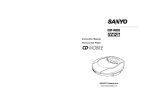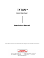
1
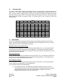
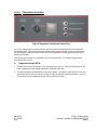
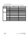
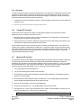
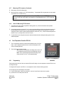
TYTANTM
Electric Water Heater
Installation Manual
Please supply your in-line heater model and serial number when ordering spare parts or requesting technical assistance.
Table of Contents
Related Documents ......................................................................................................................................................................3
Section 1:
Introduction...........................................................................................................................................................4
1.1 TYTAN DI Water Heater model number designation.........................................................................................5
1.2 Performance data ..........................................................................................................................................................8
1.3 Safety network................................................................................................................................................................8
Section 2:
Pre-Installation.....................................................................................................................................................9
Section 3:
Installation...........................................................................................................................................................10
3.1 Uncrating and inspection...........................................................................................................................................10
3.2 Mounting heater and control ....................................................................................................................................10
3.3 Plumbing connections ................................................................................................................................................10
3.4 Electrical connections ................................................................................................................................................11
3.4.1 Incoming power connections.........................................................................................................................11
3.4.2 RS232/RS485 serial communications interface (optional) ..................................................................11
3.4.3 Customer interface plug (optional)..............................................................................................................11
Section 4:
Temperature controller....................................................................................................................................12
4.1 Temperature controller E5CK..................................................................................................................................12
4.1.1 Display symbols................................................................................................................................................13
4.1.2 Selecting modes................................................................................................................................................13
4.1.3 Mode parameter settings................................................................................................................................14
4.1.4 Changing primary set point............................................................................................................................15
4.1.5 High alarm...........................................................................................................................................................16
4.1.6 Changing PID contstants................................................................................................................................16
4.1.7 Measuring PID constants...............................................................................................................................16
4.1.8 Notes on measuring PID constants ............................................................................................................17
4.2 Over-temperature controller FDC-L91 ..................................................................................................................17
4.2.1 Programming......................................................................................................................................................17
Section 5:
Operation.............................................................................................................................................................18
5.1 Cleaning .........................................................................................................................................................................18
5.2 System start-up ............................................................................................................................................................18
5.3 Normal operation.........................................................................................................................................................19
5.4 Shut down procedure.................................................................................................................................................19
Section 6:
Service and maintenance...............................................................................................................................19
6.1 Maintenance..................................................................................................................................................................19
6.2 Service policy................................................................................................................................................................20
6.3 Warranty policy.............................................................................................................................................................21
Appendix
CM-02-001
O.I. 6/27/03
ECO
TYTANu DI Water Heater
Installation, Operation and Maintenance Manual
page 2
RELATED DOCUMENTS
The following documents are to be used in conjunction with this manual:
ANSI/NFPA70 – National Electric Code®, latest edition. To be used in conjunction with electrical service, wire sizing, routing
and protection.
SEMI S2 – Semiconductor Equipment Safety Guidelines, latest edition. To be used in conjunction with safe operation, access
and decommissioning procedures.
OMRON E5CK INSTRUCTION MANUAL – Latest Edition. To be used in conjunction with accessible features of the
E5CK temperature controller. (Secure appropriate manual for any optional temperature controller used in place of the E5CK).
ANY – State or local building codes that would cover the electrical, mechanical, or physical installation of electrical heating
equipment.
National Electric Code®
NFPA 1999 Copyright
National Fire Protection Association
Quincy, Mass. 02269
CM-02-001
O.I. 6/27/03
ECO
TYTANu DI Water Heater
Installation, Operation and Maintenance Manual
page 3
Section 1:
Introduction
The Process Technology TYTANu DI Water Heater is designed to accommodate normal fluctuations in flow and process
temperatures while providing a safe, energy efficient heater. The heating elements have a durable low watt density design which
gives the element a long service life while maintaining a high flow capacity. The heating elements and wetted surfaces of the DI
Water Heater are manufactured from either Titanium or Stainless Steel as ordered by the customer. The standard Process
Technology TYTANu DI Water Heater, consisting of the heating column(s) and the complete control system, is enclosed in an
wall-mounted or freestanding painted steel enclosure.
The standard TYTANu
u DI Water Heater control system consists of the following:
PID based temperature controller with high-temperature alarm relays
Solid state control relays
Bi-metallic over- temperature Sensors
Over-temperature controller
GFP
Optional Equipment may include the following:
PLC controller
Circuit breaker and electrical disconnect
Built to SEMI and CE standards
Remote control electrical interface
RS-232, RS485 serial communication interface
Special inlet/outlet plumbing connections
Stainless steel heating column construction
CM-02-001
O.I. 6/27/03
ECO
TYTANu DI Water Heater
Installation, Operation and Maintenance Manual
page 4
1.1
TYTANu
u DI Water Heater model number designation:
Model / Part numbers are descriptive and usually follow this format.
Example:
TY – 072 – 480 – 3 - SC
Model Series:
TY = TYTAN DI Water Heater
Wattage (in kW):
072 = 72kW
Power Supply Voltage (in Volts):
480 = 480 Volts
Power Supply Phase (1 or 3):
1 = Single-phase
3 = Three-phase
Note: Some units are available only as three-phase
Options:
SC = SEMI S3 and CE compliant
CB = Include disconnect and circuit breaker
RI = Remote control interface
RC = Controller communications (RS232, RS 485)
PLC = PLC based control system
S = Stainless steel heating columns
Other Options = Consult Factory
CM-02-001
O.I. 6/27/03
ECO
TYTANu DI Water Heater
Installation, Operation and Maintenance Manual
page 5
Figure 1: Dimensional Drawing, 12kW-48kW Units.
Figure 2: Dimensional Drawing, 72kW Unit.
CM-02-001
O.I. 6/27/03
ECO
TYTANu DI Water Heater
Installation, Operation and Maintenance Manual
page 6
Figure 3: Dimensional Drawing, 96kW-144kW Units.
CM-02-001
O.I. 6/27/03
ECO
TYTANu DI Water Heater
Installation, Operation and Maintenance Manual
page 7
1.2
Performance Data:
The TYTANu DI Water Heater is designed for inline heating of DI water. It will perform both as a recirculating heater, and as a
one-pass heater. The TYTANu DI Water Heater is designed to provide a specified temperature increase at a given flow rate.
Table 1 shows the maximum temperature increase (∆T) that can be achieved for continuous flow conditions at the specific
heater power ratings varying from 24kW to 144 kW (Higher wattage systems available upon request). The temperature control
system provided with the heater will modulate the power to the heating columns in order to maintain your specific outlet
temperature setting.
kW
GPM
2
4
6
8
10
12
14
16
18
20
1.3
Table 1
60
72
96
120
144
o
∆T F
82
41
51
82
27
34
55
68
82
20
26
41
51
61
82
16
20
33
41
49
65
82
14
17
27
34
41
55
68
82
12
15
23
29
35
47
58
70
10
13
20
26
31
41
51
61
9
11
18
23
27
36
45
55
8
10
16
20
25
33
41
49
Temperature increase (oF) as a function of power (kW) and flow rate (GPM)
24
30
48
Safety Network:
The TYTANu DI Water Heater is protected from accidental damage or unsafe operating conditions with a network of safety
interlocks. The safety interlocks will disengage power to the heaters until power is manually restored at the control. The safety
interlocks offered on the TYTANu DI Water Heater are listed below.
Bi-Metallic Heater Over-Temperature Sensor:
The temperature of the heating elements is continuously monitored by these bimetallic sensors. Any over-temperature situation
will cause the main load contactor to disengage, and sound the audible alarm. This will require a manual reset of the heater
once the overheat event has been corrected. The over temperature sensors are provided with a fixed setting of 262°F (128°C).
(Maximum Element Surface Temperature)
High Temperature Alarm:
The High Temperature Alarm setting on the OMRON E5CK is factory set at 248°F (120°C). If this temperature is detected at the
process sensor. the controller will disengage the main load contactor and sound the audible alarm. This will require a manual
reset of the heater once the overheat event has been corrected.
Over-Temperature Controller:
This over-temperature controller is a separate controller mounted inside the control enclosure. It uses a separate temperature
sensor to monitor the hot-zone temperature in one of the heating columns.
This over-temperature controller has two different settings:
1. Over-temperature cutoff (SP2). This setting needs to be adjusted manually by the customer, to be set 18°F
(10°C) higher than the set point of the Omron Temperature controller. This setting will cutoff power to the heaters
if the internal temperature rises above this value, but will automatically re-engage the heaters when the
temperature drops below this value. This is not an alarm set point.
CM-02-001
O.I. 6/27/03
ECO
TYTANu DI Water Heater
Installation, Operation and Maintenance Manual
page 8
1.3
Safety Network: (Continued)
2. High Limit (HSP1). This high-temperature alarm setting is set at 248°F (120°C). If this temperature is detected at
this sensor. the controller will disengage the main load contactor and sound the audible alarm. This will require a
manual reset of the heater once the overheat event has been corrected.
Pressure Relief Valve:
The heating columns are protected from pressures over 100 PSI (6.9 Bar) by a type 316 stainless steel Pressure Relief Valve
(PRV) mounted on the inlet of the heater. If the column pressure exceeds 100 PSI (6.9 Bar), the pressure relief valve will open
and vent excess water pressure to the drain.
Section 2:
Pre-Installation:
Note: Before beginning installation of the TYTANu DI Water Heater, carefully read this entire section.
1)
Space Requirements: The standard dimensions of the various models are shown in Table 2 (see appendix for custom made
units). Allow additional space on all sides of the unit for the control ventilation and service access. (all dimensions are in
inches).
Table 2
kW
12-48
72
96-144
Dimensions
Width
Depth
29 ½” (750mm)
13 ½” (343mm)
37 ½” (953mm)
13 ½” (343mm)
28” (712mm)
17” (432mm)
Height
36” (915mm)
36” (915mm)
63” (1601mm)
2)
Inlet and Outlet Plumbing: The TYTANu DI Water Heater is supplied with customer specified inlet and outlet plumbing
connections. Reference the specific model number ordered and section 1.1 “TYTANu DI Water Heater Model Number
Designation” of this manual to confirm the required plumbing connections.
3)
Electrical Connections: The TYTANu DI Water Heater is supplied with customer specified power requirements. Reference
the specific model number ordered and section 1.1 “TYTANu DI Water Heater Model Number Designation” of this manual
for the required power connections. Confirm these requirements by checking the product identification tag located on the
lower right-hand corner of the cabinet (see figures 1-3). Fuse the incoming power line for the rated amperage using an
approved electrical disconnect box.
CM-02-001
O.I. 6/27/03
ECO
TYTANu DI Water Heater
Installation, Operation and Maintenance Manual
page 9
Section 3:
3.1
Installation:
Uncrating and Inspection:
1)
The TYTANu DI Water Heaters are crated and shipped in an upright position. If the unit is not upright, return the crate to
an upright position and inspect carefully.
2)
Remove front side of the crate.
3)
Remove the protective packaging material.
4)
Remove the unit from crate by grasping the sides of the cabinet.
5)
Inspect the unit for any apparent damage.
3.2
Mounting Heater and Control:
1)
Location: TYTANu DI Water Heaters are designed for remote installation, keeping point of use areas uncluttered and free
of potential contaminants. The unit is designed to use a minimum amount of wall space or floor space making chase areas
suitable location for installation.
2)
Mounting: The TYTANu DI Water Heater is designed to be wall mounted or free standing. However the TYTANu DI
Water Heater should be placed in a vertical and level position.
3.3
Plumbing Connections:
DI Water Line Connections:
1)
Remove the protective plastic caps from inlet and outlet plumbing on the heater column.
2)
Locate the inlet and make the required connection to the customer supplied fitting. (Do not reverse).
3)
Tighten the connection as required. Take care not to over-tighten.
4)
Repeating the above procedure for the outlet plumbing.
5)
Locate the pressure-relief valve (PRV): on the underside of the heater enclosure, adjacent to the inlet for 12-72kW units, or
on the back of the enclosure just above the inlet for 96-144kW units. Plumb the PRV to a zero-pressure drain.
Note: For convenience of draining the heating columns during extended shut down periods, the plumbing
connections to the DI Water Heater Inlet should contain a drain assembly.
CM-02-001
O.I. 6/27/03
ECO
TYTANu DI Water Heater
Installation, Operation and Maintenance Manual
page 10
Electrical Connections:
3.4
3.4.1
Incoming Power Connections:
TYTANu DI Water Heaters are designed to operate on 4 or 5 wire electrical supplies (3 power wires, 1 ground wire). All
electrical connections should conform to local electrical codes and/or NFPA 70/79.
1) Check the system tag located on the equipment for Power Requirements . Do not operate this heater on Voltages other
than the Voltage rating on the system tag.
2)
Remove lower front cover of the cabinet by loosening all cover mounting screws.
3)
Fuse the incoming line for the rated amperage using an approved electrical disconnect box.
4)
Supply power to the unit from the electrical panel into the cabinet through the opening at the “service entrance”. This
opening will need to be made by the customer. Ensure that the wire has sufficient amp capacity to safely carry the power
load.
5)
Connect the leads from the incoming power line to the appropriate terminals (reference the Electrical Schematic) making
sure not to disturb existing wiring. Use care that no loose strands of wire are exposed out of the Terminal Block. Torque all
wires to the specified ratings located on the wiring diagrams and component labels.
6)
Grounding is done internally from the Incoming Power Strip. Reference the wiring diagram in the appendix.
3.4.2
RS-232 / RS-485 Serial Communication Interface (Optional):
In units supplied with the RS-232 / RS-485 serial communication interface, the Temperature Controller is equipped with RS-232 /
RS-485 Serial Communication capability for use with a customer-supplied host computer. If this option is used, all temperature
and related parameters can be monitored or altered from the host computer. On standard units, the DB-9 receptacle(s), labeled
REMOTE COMMUNICATIONS, is(are) located at the rear (or bottom) of the cabinet. An independent serial cable should be
installed between the host computer and the DB-9 receptacle.
3.4.3
Customer Interface Plug (Optional):
The Auxiliary Equipment Interface Plug is used for communication between the Process Controller and customer-supplied
devices. The interface plug is located on the rear (or bottom) of the Cabinet enclosure. Refer to dimensional drawings in the
appendix.
Ø
Reference the electrical drawings supplied in the appendix for options provided and proper interface connector pin
orientation.
CM-02-001
O.I. 6/27/03
ECO
TYTANu DI Water Heater
Installation, Operation and Maintenance Manual
page 11
Section 4:
Temperature Controller:
Figure 4: Temperature Controller and Control Panel.
The TYTANu Heating System incorporates a self-tuning, PID microprocessor based, digital temperature controller with a set
high temperature alarm. The PID feature enhances the controller's ability to reach and maintain a constant process temperature.
The self-tuning feature enables the controller to measure the process characteristics and indicate desired values, which can be
displayed on LED displays.
This section provides a description of, and instructions for the Omron E5CK Controller. For a complete user guide, see the
Omron website, www.omron.com.
4.1
Temperature Controller E5CK:
1. The E5CK controller has two LED displays. The top LED displays the process value, modes and parameter symbols. The
bottom LED displays Set Points, parameter setting and the manipulated variable, heat.
2. The A/M key switches the controller between auto and manual operation. The Display Key when pressed for one second or
greater allows selection of the mode, and when pressed for less than one second the parameters are switched. The up and
down arrow keys advance decreases the setting or values in the bottom LED display.
CM-02-001
O.I. 6/27/03
ECO
TYTANu DI Water Heater
Installation, Operation and Maintenance Manual
page 12
4.1.1
Display Symbols:
The following tables show the correspondence between symbols shown on the displays and alphabetic characters.
4.1.2
Selecting Modes:
The modes are selected by pressing the Display Key for one second or greater. The up and down arrow keys allow the
movement between modes in the top display.
CM-02-001
O.I. 6/27/03
ECO
Lv–0
Level 0
Lv-1
Lv–2
SEt
Ext
oPT
CLb
Level 1
Level 2
Setup
Expansion
Option
Calibration
TYTANu DI Water Heater
Installation, Operation and Maintenance Manual
page 13
4.1.3
Mode Parameter Settings:
Omron E5CK temperature controller: When in the selected mode press the Display Key for less than one second to switch
parameters.
Mode
Level 0
Level 1
Level 2
Parameter
r–S
At
AL–1
AL–2
P
i
D
CP
SPrU
SPrt
mU – S
mU – E
OL–H
OL–L
OrL
inF
ALH1
ALH2
ALH3
inSH
inSL
CM-02-001
O.I. 6/27/03
ECO
Description
Setting
Run/Stop
Auto Tune (AT) execute/cancel
High Alarm
Temperature Deviation
Proportional Band
Integral Time
Derivative Time
Heating Control Period/Cycle Time
Set Point ramp time unit
Set Point ramp set value
Sets Manipulated Variable (MV) when operation
stop
Sets MV when an input error occurs
MV upper limit
MV lower limit
Max. allowed change width of MV / change rate
limit
Input digital filter constant
Alarm 1 hysteresis
Alarm 2 hysteresis
Alarm 3 hysteresis
Input shift upper limit temperature
Input shift lower limit temperature
Run
O-FF
120°C
110°C
10.0 (default)
233 (default)
40 (default)
1sec
M, minutes
0
0.0%
0.0%
105.0%
0.0%
0.0%/sec (= disabled)
0 sec
1.00%
1.00%
0.01%
Factory Calibrated
Factory Calibrated
TYTANu DI Water Heater
Installation, Operation and Maintenance Manual
page 14
4.1.3
Mode Parameter Settings: (Continued)
Mode
Parameter
in–t
d –U
init
OUt1
OUt2
SUb1
ALt1
AL1n
ALt2
AL2n
OrEv
Setup
Option
(RS 232)
(RS 485)
4.1.4
Default Setting
Sensor type
Set temperature input as OC or OF
Parameter Initialize Yes/No
Control Output 1 assignment
Control Output 2 assignment
Auxiliary Output 1 assignment
Alarm 1 type
Output State of Alarm 1
4
C
No
Heat
AL-1 (alarm 1)
AL-2 (Deviation Alarm)
8 (upper limit alarm)
n – C (open in Alarm, LED lit)
8 (upper limit alarm)
n – O (Closed in Alarm, LED lit)
or – r (Reverse)
St
ALFA
At – G
rESt
rEt
At – H
SbIt
LEn
PrtY
bPS
Alarm 2 type
Output State of Alarm 2
Direct / Reverse operation between MV and
process value
Set Point upper limit
Set Point lower limit
Switch between advanced PID control and
ON/OFF control
Self Tuning function
Advanced PID control Alpha
AT calculated gain
Standby sequence reset method
Automatic return of display mode
AT hysteresis
Communication stop bit
Communication data length
Communication parity
Communication baud rate
OFF
0.65
1.0
0 (condition A)
0 (disabled)
0.2% FS
2 bits
7 bits
Even
9.6 KBPS
U–no
Communication unit number
0
SL–H
SL–L
CntL
Expansion
Description
100
0
PID
Changing Primary Set Point:
1. Set Points can be changed in the mode level 1.
2. Press the Display Key for less than one second to switch parameters.
3. Press the up and down arrow keys to select the desired value. The decimal point is sensor dependent.
4. After changing the set point on the Omron controller, you must manually adjust the SP2 setting on the overtemperature control. (See page 17)
CM-02-001
O.I. 6/27/03
ECO
TYTANu DI Water Heater
Installation, Operation and Maintenance Manual
page 15
4.1.5 High Alarm:
The Digital Temperature Controller incorporates an independent alarm. The High Process Temperature Alarm prevents heater
operation above a preset maximum temperature that may harm the process and potentially the tank material. If the process
temperature exceeds the preset high alarm value, the heater will be disengaged. The temperature controller will activate once
the process temperature exceeds the set point by the preset value.
1. The high alarm value can be user defined in mode Level 1 Press the Display Key for less than one second to switch to the
parameter for alarm 1.
2. Press the up and d own arrow keys to select the desired value.
4.1.6
Changing PID Constants:
Twenty -five percent (25%) attenuation is considered most appropriate for adjustment of the measured PID constants.
Depending on their use, the following circumstances may arise.
Ø
When the occurrence of an overshoot poses no problem, the temperature of the controlled system can approach the set
temperature and become stable in a short period of time.
Ø
When the occurrence of an overshoot is undesirable, a longer period of time should be allowed for the temperature of the
controlled system to approach the set temperature and become stable.
The PID constants measured under such circumstances may not be optimum for temperature control. In such case, the PID
constants may be changed or modified within their variable range. To change PID constants, turn the PID constant measuring
switch to the test position and then return it to the control position. This allows the controller to read the new PID constants. This
read operation may also be performed by turning the power to the temperature controller OFF and ON. If any process is
changed, recalibrate the temperature controller.
4.1.7
Measuring PID Constants:
The Temperature Controller has the capability of automatically tuning the PID parameters to fit the characteristics of the process.
The optimum PID parameters are automatically set by forcibly changing the Manipulated Variable (MV) to calculate the
characteristics (limit cycle method) of the control target. Depending on the auto-tune level selected, AT-1 or AT-2, the controller
will run this test at either 40% or 100% of the actual Process Set Point. When the auto tuning is complete, the appropriate PID
tuning parameters will be automatically installed into the non-volatile memory of the temperature controller.
1. Turn on water supply and set the desired water flow.
2. Turn on power to the temperature controller via the power switch.
3. Set the temperature controller's high set point setting to the desired operating temperature. This temperature must be at
least 36°F (20°C) above ambient.
4. Set the temperature controller's high alarm setting to the desired value. This is a deviation-type alarm that will operate
when the "displayed" temperature drifts above the set point plus this value.
5. Advance to the AT Parameter in mode Level 1using the Display Key.
6. Using the Up arrow key select “AT-2”. The controller will begin to perform its auto-tune test.
7. Press Display Key for 1 second to return to the beginning of Level 1 Mode. Press the DOWN Key to advance to Level 0
Mode, then hold display Key for 1 second to return to operating mode.
NOTE: While in the tuning mode, the “AT” auto-tune LED will flash.
CM-02-001
O.I. 6/27/03
ECO
TYTANu DI Water Heater
Installation, Operation and Maintenance Manual
page 16
4.1.7
Measuring PID Constants: (Continued)
8. Start heater(s) via the Off-On-Reset switch.
9. When the process is complete, the “AT” LED will stop flashing. The appropriate PID tuning parameters are now installed
and retained in the non-volatile memory.
Note: To abort auto tuning, the operator must reset the "AT" parameter to "OFF". This leaves the
unit in an On/Off heat control state in auto operation at the displayed set point. All PID values are
set to "0".
4.1.8
Notes On Measuring PID Constants:
1. The measurement of PID constants is applicable to heating systems only. Start the measurement with temperature
balanced in the controlled system.
2. If the indicated temperature is below 36°F (20°C) and the temperature difference between the indicated temperature and
the set temperature is not at least 36°F (20°C) the measurement of PID constants can not be performed. In such case,
change the set value to obtain a greater temperature difference (at least 36°F (20°C).) When the indicated temperature is
below 36°F (20°C), manually raise it to above 36°F (20°C).
3. If a power failure occurs during the measurement, restart the measurement after returning the heating system to normal
ambient temperature.
Over-Temperature Controller FDC-L91:
4.2
1. This over-temperature controller is located inside the electrical portion of the Tytan
heater. It uses a separate temperature sensor to monitor the temperature on the
surface of the heating elements.
2. This controller has two discreet set points:
SP2: This is the over-temperature cutoff setting, which is set for 18°F
(10°C) ABOVE the primary set point on the temperature controller.
HSP1: This is an element high-temperature alarm setting, which is
factory set at 248°F (120°C). Do not adjust this setting.
4.2.1
Programming:
Figure 5: Over-temperature
controller
Every time the primary set point of the main controller E5CK, the SP2 setting on the over-temperature controller FDC-L91 must
be changed manually.
To Change the SP2 set point on the FDC-L91 over-temperature controller, follow the following procedure:
Do not change any of the other settings in this controller.
1 ) Turn the “Enable Heater” switch to the Off position. Leave the “Control Power” switch in the On position.
2 ) Open the door to the control-portion of the unit.
CM-02-001
O.I. 6/27/03
ECO
TYTANu DI Water Heater
Installation, Operation and Maintenance Manual
page 17
4.2.1
Programming: (Continued)
Caution: When the enclosure door is open, be careful not to touch the electrified components inside. To avoid shock
hazard, this procedure should only be performed by qualified personnell.
3 ) Identify the over-temperature controller, tagged 1SLC.
4 ) Press the Index key (
) twice until “SP2” is highlighted.
5 ) Using the “p” or “q” buttons, adjust the SP2 value until it is 18°F (10°C) higher than the set point on the temperature
controller. Note: Do not change any other settings on this controller.
6 ) Close the door to the control portion of the enclosure.
7 ) Follow the procedure for “System Startup” (page 17) to start the heater.
Section 5:
5.1
Operation:
Cleaning:
The TYTANu DI Water Heater was thoroughly cleaned before shipment. However, cleaning will be required prior to startup to
remove any contaminants resulting from the shipping and installation process. Process Technology recommends that the
following procedure be followed at a minimum. If the system is to be used with ultra pure DI water (15 Meg ohm or higher)
additional steps may be required in certain applications.
1)
Allow the unit to flow to drain with as high as flow rate of DI water as possible for several hours. The recommended
minimum flow rate is 3-5 GPM (11-19 LPM).
2)
Operate the TYTANu DI Water Heater for several hours at the greatest DI water flow rate that will allow an exit temperature
not exceeding 60°C(140°F.)
Caution: Ensure that all drain lines are capable of withstanding pressures and temperatures that will be
produced within the TYTANu water heater.
3)
Perform normal sanitizing procedure commonly used on existing DI water plumbing network.
4)
Perform normal after-sanitizing rinse procedure.
Note: The actual times required for absolute clean up of the system may vary dependent on DI water quality,
flow rates and installation techniques.
5.2
System Start-Up:
After completing installation, the following calibrations must be performed before operating the heater.
1)
Check the switch positions on the control interface (if supplied).
Caution: All switches should be in the off position.
2)
Turn on water at its supply source. Allow sufficient water to flow through the column to remove any entrapped air pockets.
3)
Stop water flow at point of use location and check all plumbing connections and water heater for leaks.
4)
Engage electrical supply at customer's source. Ensure that OPTIONAL circuit breaker(s) are in the "ON" position.
CM-02-001
O.I. 6/27/03
ECO
TYTANu DI Water Heater
Installation, Operation and Maintenance Manual
page 18
5.2
5)
System Start-Up: (Continued)
Engage the "CONTROL POWER" switch on the control panel. At this time the temperature controller and all optional
displays will come on.
Note: Temperature controller set point should be set to "0" at this time to prevent accidental heater
engagement during calibration procedures. Reference temperature controller section if required.
5.3
Normal Operation:
Normal operation of the TYTANu DI Water Heater will consist of the following steps:
1)
Initiate water flow. Allow water to flow for several minutes to ensure all entrapped air has been removed from column(s).
2)
Make sure that the “Off-On-Reset” switch is in the “Off” position.
3)
Energize the unit by turning on the Electrical Disconnect.
4)
Turn the “Control Power” switch to the “On” position.
5)
Adjust the desired set point on the temperature controller.
6)
Turn the “Off-On-Reset” switch all the way to the “Reset” position and release to the “On” position. If all safety circuit
requirements are satisfied, the heaters will operate at this point.
Note: If the temperature set point is changed, it is necessary to recalibrate the temperature controller.
5.4
Shut Down Procedure:
1)
Turn “Off-On-Reset” switch to “Off”.
2)
Allow heater to cool to a maximum of 95°F (35°C).
3)
Turn Main Power OFF.
Note: When long shut down periods are required, drain system, and dry heater by blowing inert gas through
piping system.
Note: No scheduled maintenance is required for DI heating systems. However, it is recommended to
replace the SSR relays every 24 to 30 months as some applications may exceed the SSR relay cycle life.
Section 6:
6.1
Service and Maintenance:
Maintenance:
Normal maintenance of TYTANu DI Water Heaters consists of the following:
1)
Disinfect the water heater along with the rest of the plumbing system on a regular basis if continuous sanitizing such as
ozone injection is not employed.
2)
Replace the temperature sensors every 24 months.
3)
Replace the heater control relays and fan after approximately 24-30 months of use. Actual life expectancy varies with
application conditions such as hours of operation, control tuning parameters, applied voltage and amperage.
4)
The Solid State Relay fan should be replaced and the heat sink is to be cleaned every 24 months.
CM-02-001
O.I. 6/27/03
ECO
TYTANu DI Water Heater
Installation, Operation and Maintenance Manual
page 19
Service Policy:
6.2
Process Technology supports its product line with a strong technical support and field service program. If your TYTAN™ DI
Water Heater fails to perform properly, follow the outlined steps for resolution.
Note: If the unit was damaged in transit, contact the freight carrier directly. Process Technology is not
responsible for shipping damage.
1)
Verify connections and program parameters.
2)
Contact the Process Technology Technical Service Group. When placing this call, please have available the model
number and serial number of the unit (located on the system tag), information about the application of the equipment,
and information regarding the chemical constituents of the process fluid. The Service Technician will evaluate the
situation and determine a course of action for troubleshooting and repair.
3)
If the Technician determines that the unit should be returned to the factory for evaluation, a Return Material
Authorization (RMA) Number will be issued. A return will not be accepted without prior authorization.
Note: Equipment must be returned to Process Technology within 30 days of return authorization.
Typically, the TYTANu DI Water Heater will not have been exposed to chemicals. However, Process Technology
personnel are instructed to handle any returned equipment as if it contains residual chemicals. A package containing
returned equipment will not be opened until chemical information is received. Therefore, Process Technology requires
that the following procedures be followed for all returns, whether or not they are likely to contain chemical residues.
To protect the safety of Process Technology’s workers and any others that may come in contact with this equipment in the
course of transport, evaluation, and repair, Process Technology requires that these practices be followed in returning the
equipment to the factory:
1)
Rinse the equipment until it is free of any chemical residues and drain any fluid from elements and piping. This is
required for safe transport and handling of the equipment.
2)
Wrap the unit in plastic and secure. Make sure that it does not leak. (Process Technology is not responsible for
damage caused by leakage during shipping.)
3)
Carefully package the unit for shipment.
4)
Indicate the type of chemical (this includes DI Water) that was in use at the time of failure. Include this information on
the packing slip or place the information on the outside of the box. Process Technology will not risk exposure of its
personnel to unknown chemicals. A return will not be evaluated until chemical information is received.
5)
Clearly mark the outside of the box with the RMA number.
6)
Ship the component to Process Technology via prepaid freight.
Upon receipt of a returned unit, Process Technology will follow these steps:
1)
The equipment will be carefully unpacked, inspected and cleaned, and an evaluation will be done.
2)
A Process Technology technician will contact the customer with information regarding the scope of work to be
performed, the cost, and the amount of time needed.
3)
After a purchase order and authorization to perform the repair are received, the repairs will be completed and the unit
returned.
4)
If the returned unit has been used in a chemical application and Process Technology determines that it is not
repairable, the equipment will be returned at Process Technology’s expense to the customer site for proper disposal.
CM-02-001
O.I. 6/27/03
ECO
TYTANu DI Water Heater
Installation, Operation and Maintenance Manual
page 20
6.3
Warranty:
All products and components not manufactured by Process Technology will carry the original manufacturer's warranty,
copies of which are available upon request. Process Technology makes no warranty or representation, expressed or
implied, with respect to the products not manufactured by Process Technology.
Process Technology industrial products are warranted against defects in materials and workmanship for a period of one year
from date of shipment and this is applied on a pro-rated basis. At its option, Process Technology will repair or replace defective
equipment.
Users are responsible for the suitability of the products to their application.
Process Technology disclaims responsibility for failure arising from misuse, negligence, improper installation, tampering or
other operating conditions beyond its control (such as low solution level.)
Products must be installed and maintained in accordance with Process Technology instructions.
Process Technology is not liable for labor costs incurred in removal, reinstallation, or unauthorized repair of the product or for
damage of any type including incidental or consequential damage.
Process Technology, neither assumes or authorizes any representative of Process Technology or any other person to
assume for it any other liabilities in connection with the sale of the products. This warranty may not be verbally changed or
modified by any representative of Process Technology.
Damages
Claims against freight carriers for damage in transit must be filed by the buyer at the time of delivery if possible.
Returns
No product shall be returned to Process Technology without first obtaining return authorization from a Process Technology
representative. All returns must be freight prepaid. Freight collect or shipments without authorization will be refused.
Information
Process Technology will endeavor to furnish such advise as it may be able to supply with reference to the use by buyer or any
material purchased, but Process Technology makes no guarantees and assumes no obligation or liability for advice given
verbally or in print or the results obtained. Buyer assumes all risk and liability which may result from the use of any material,
whether used by itself or in combination with other products. No suggestion for product use shall be construed as a
recommendation for its use in infringement on any existing patent.
Cancellation
Process Technology will not accept cancellation or changes to orders that are in production or scheduled for production. At
Process Technology's option, changes or cancellations may be made upon payment of reasonable cancellation charges that
take into account expenses already incurred and commitments made by Process Technology.
Conflict Between Documents
Acceptance of this offer is expressly conditioned upon agreement to all terms and conditions contained herein. In the event of a
conflict between the terms and conditions of purchaser's purchase order, and Process Technology's terms and conditions,
proposal or offer, the latter shall govern.
CM-02-001
O.I. 6/27/03
ECO
TYTANu DI Water Heater
Installation, Operation and Maintenance Manual
page 21