1
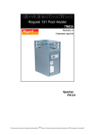
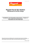
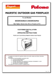
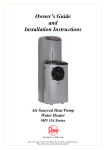
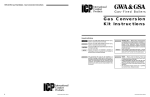
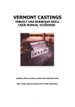
Raypak Pool & Spa Gas Heaters
Residential & Premium Range
Owner’s Guide and Installation Instructions
Natural Gas
Residential Pool & Spa
Heater Models:
Premium Pool & Spa
Heater Models:
Models
Propane
P0131NCO/OD
P0200-N
P0280-N
P0350-N
P0430-N
P0131PCO/OD
P0200-P
P0280-P
P0350-P
P0430-P
P0127NNO
P0167NNO
PC0280-N
PC0430-N
P0127PNO
P0167PNO
PC0280-P
PC0430-P
Please read this manual prior to installing this product. It contains all the necessary technical and installation
information that will be required by the contractor to correctly install this system. This product must be installed in
accordance with the installation instructions and in compliance with standards AS5601 or AS/NZS 5601.1, AS/NZS
3500.4:2003:2003, AS/NZS 3000:2007, the relevant electrical authorities’ requirements and all local codes and
regulatory requirements.
Part No: 96131430
1
Rev: D
TABLE OF CONTENTS
SAFETY ......................................................................................................................................................... 3 WATER TREATMENT.................................................................................................................................... 3 INSTALLATION INSTRUCTIONS .................................................................................................................. 4 PRECAUTIONS.............................................................................................................................................. 8 PERIODIC MAINTENANCE ........................................................................................................................... 9 COMMISSIONING........................................................................................................................................ 10 RESET BUTTON .......................................................................................................................................... 11 OPERATING INSTRUCTIONS .................................................................................................................... 13 PROGRAMMING OF HEATER CONTROLLER .......................................................................................... 15 ELECTRICAL CONNECTIONS .................................................................................................................... 17 DIMENSIONAL & TECHNICAL DATA ......................................................................................................... 20 WIRING DIAGRAMS .................................................................................................................................... 23 POOL HEATER OPERATION FLOW CHART ............................................................................................. 27 RHEEM WARRANTY (AUSTRALIA ONLY) ................................................................................................. 29 Date of installation:
Model No.
Serial No.
Installed by:
Purchased from:
This Owners Guide and Installation Instructions manual is provided with the necessary information for the proper
installation, operation and maintenance of your Raypak pool or spa heater. Please review and follow these
procedures carefully. Keep this manual in a safe and accessible place for easy reference in the future.
Note: Every care has been taken to ensure accuracy in preparation of this publication.
No liability can be accepted for an consequences, which may arise as a result of its application.
Part No: 96131430
2
Rev: D
SAFETY
WARNING!
For your safety do not operate this appliance before reading this instruction booklet! Improper installation, adjustment, alteration,
service or maintenance can cause injury or property damage.
DO NOT place articles on or against this appliance.
DO NOT use or store flammable materials near this appliance.
DO NOT spray aerosols in the vicinity of this appliance while it is in operation.
DO NOT operate this appliance with any panels, covers or guards removed.
DO NOT enclose this appliance unless it has been constructed for such an installation.
DO NOT operate this appliance whilst a suction plate is fitted in the skimmer box for cleaning your pool. E.g.: With a vacuum hose
suction operated cleaning device
DO NOT use this appliance to heat water for drinking.
DO NOT enter water heated by this appliance without testing temperature first. Prolonged exposure to elevated water
temperatures may be hazardous to your health.
WHAT TO DO IF YOU SMELL GAS!
¾
¾
¾
DO NOT try to light this appliance.
DO NOT touch any electrical switch.
TURN OFF the gas supply at the meter immediately, contact an qualified gas fitter or Rheem Service. Note: Some
gases are heavier than air and it may be necessary to check for gas leaks at floor level.
Ceramic Fire tile refractory is used in this appliance. For a current Material Safety Data Sheet (MSDS) go to
www.thermalceramics.com and enter “MSDS 354” in the search. Ceramic Fire tile refractory may produce smoke when the
appliance is first started. Ensure area is well ventilated when lighting appliance. Avoid breathing fumes.
For your own safety only have this appliance installed by an qualified gas fitter who must issue you with a compliance certificate
when complete. Persons taking medications which induce drowsiness should not use spas. Persons with a medical history of heart
disease circulatory or blood pressure problems, or diabetes should obtain their Doctor’s advice prior to using a spa.
WATER TREATMENT
IMPORTANT! CORROSIVE WATER VOIDS YOUR WARRANTY.
This pool or spa heater must be installed in accordance with this advice to be covered by Rheem’s warranty. This pool or spa
heater is manufactured to suit the water balance specified on the table below. However, there are some known water chemistries
which can have detrimental effects on the pool or spa heater and its operation and/or life expectancy. This pool or spa heater must
be installed in accordance with this advice to be covered by the Rheem warranty
For your health and the protection of your heater it is essential that your water quality is always chemically balanced. Only incorrect
water balance will cause your heat exchanger to corrode. After corrosion occurs, subsequent water chemical tests may not reveal
the water quality at the time that the damage occurred. Do not replace any corroded parts before bringing your water quality back
into balance. The following table provides a guide to good water balance:
pH
Total Alkalinity (PPM)
Calcium Hardness (PPM)
Salt (PPM)
Free Chlorine (PPM)*
Langelier Saturation Index
Fibreglass Pools
(less than 31C)
7.3 - 7.4
120 - 150
200 - 300
6,000 MAX
2-3
±0.3
Fibreglass Spas
(more than 31C)
7.3 - 7.4
120 - 150
200 - 300
6,000 MAX
2-3
±0.3
Other Pools &
Spas
7.6 - 7.8
80 - 120
200 - 400
6,000 MAX
2-3
±0.3
* FREE CHLORINE MUST NOT EXCEED 4 PPM
* FREE BROMINE MUST NOT EXCEED 5 PPM
There are several factors that need to be considered in order to avoid damage to your heater.
•
Automatic chemical dosing devices and chlorinators are usually more efficient in heated water and/or covered pools/spas.
Unless controlled, they may lead to excessive chlorine levels which can damage your heater.
•
If the sanitising level in your pool/spa is too high, your test kit or that of your pool shop may not show the correct
chlorine/bromine concentration.
•
If your salt chlorinator operates for extended periods whilst the pool is being heated and the weather is overcast or your
pool is enclosed / covered, the chlorine may exceed the recommended levels.
•
The balance of your pool water depends on a combination of pH, total alkalinity, calcium hardness and temperature.
Combined, these factors enable the Langelier Saturation Index to be calculated. It is essential these factors are
maintained at the recommended levels so that the water is balanced and the sanitation of your pool will be optimal.
•
When adding acid to lower your pH, it must always be added in small quantities and spread uniformly over the entire pool
surface. DO NOT add acid one litre at a time. Instead, add a cupful each day. DO NOT add acid into the skimmer box.
This may potentially lead to corrosion of your heat exchanger. Refer to “Periodic Maintenance” on page 9.
Part No: 96131430
3
Rev: D
INSTALLATION INSTRUCTIONS
ATTENTION! This appliance must be installed in accordance with all local state and federal laws including the regulations of any
government bodies and in complete accordance with these instructions. Where these instructions are contrary to the law or
regulations of an appropriate government body those laws or regulations should take precedence subject to there being no
compromise to safety.
BEFORE YOU COMMENCE INSTALLATION
1.
Read these instructions in full.
2.
Check that the pool or spa heater you have been supplied is suitable for the gas type that is available.
3.
Ensure that your gas fitter checks that the gas supply pressure is between the minimum and maximum specified on the heater
data plate.
4.
Confirm that the heater you have purchased is suitable for the location it is to be installed, i.e. Outdoor or Indoor.
5.
Check that your pool system pump will provide water flow between the specified minimum and maximum flow rates required
for the heater to operate.
6.
Remove packaging and timber base before installation.
7.
Complete all details on the back page of this book.
PRODUCT APPLICATIONS
Raypak “Residential” pool & spa heaters are designed and built for installation in applications where the intention of its use is to
heat a pool or spa of a single family dwelling. Its use in an application other than this may shorten its life. Residential heaters are
not intended for installation in commercial applications such as multi residential apartments. For these applications a Raypak
“Commercial” pool or spa heater (also referred to as “Premium”) pool or spa heater should be selected.
See WARRANTY & SERVICE section in this book for details of the different Rheem warranties dependent on the heater type and
its intended application.
HEATER LOCATION
The heater must be located so that any possible water leaks will not damage adjacent areas or structures. When such locations
cannot be avoided it is recommended that a suitable safe tray be constructed and installed by your plumber. This must not restrict
air required for combustion.
The heater must be located on a level non-combustible surface such as concrete. All packaging must be removed before
installation.
OUTDOOR HEATERS
Raypak pool & spa heaters are built for outdoor installations as standard. The installation must conform to AS5601 OR AS/NZS
5601.1 as a minimum. They must not be installed in any enclosed structure or under eaves, roof overhangs, or pool decks.
Outdoor pool & spa heaters must be installed at least 1500mm from any window or room ventilation opening. They must also have
no obstructions above the appliance.
If installing the heater on a raised base, the base must be non-combustible and contain no air openings or perforations. Drafts from
below the heater can affect its operation.
High Wind Areas
Raypak pool & spa heaters are atmospherically vented and so may not function correctly in areas of sudden changing air pressure
often caused by high or variable wind speeds. In some instances, it may be necessary to install either a Raypak High Wind Top
or a Raypak Induced Draft Fan to ensure correct operation. These options should be discussed with Rheem before installation.
In areas of "constant extreme winds" or in areas where high winds frequently occur, it is necessary to locate the heater a minimum
of one (1) metre from high vertical walls, or install a wind break so that the heater is not positioned and exposed in the direction of
the prevailing winds.
INDOOR HEATERS
Combustion / Ventilation Air
Indoor pool & spa heaters must only be installed in a protective enclosure or properly constructed room, with ventilation in
accordance with AS5601 OR AS/NZS 5601.1. Ventilation must be provided via two permanent openings, one at ceiling level and
one at floor level. Minimum vent area must be in accordance with AS5601 OR AS/NZS 5601.1. Minimum opening dimensions in
the vent must be at least 6mm.
For indoor applications the pool or spa heater must have at least the minimum clearances specified in the table below on page 5.
Increased clearances should be provided where possible to improve serviceability. If the pool or spa heater is not installed in
accordance with the sufficient and safe space for ease of service around the unit, Rheem advises that the pool or spa heater will
be disconnected and removed to enable servicing.
Part No: 96131430
4
Rev: D
Note: The following table details minimum acceptable clearances (mm) for serviceability and for indoor installations on noncombustible floors only:
Models P0127, P0200, P0280, P0350, P0430, PC0280, PC0430
Rear
150
500
Front Water Non-Water Above
Side
Side
Non-Combustible Surfaces
750
600
150
1200
Combustible Surfaces
750
600
500
1200
Models P0131*, P0167
Rear
300
500
Front
Left
Right Above
Non-Combustible Surfaces
750
300
300
1200
Combustible Surfaces
750
500
500
1200
*Model 131 suitable for outdoor installations only.
Note: For outdoor clearances refer to AS/NZS5601.1:2010
Air supply to the room must not be affected by mechanical exhausts of other equipment such as bathroom or kitchen fans, spa
blowers or air-conditioning equipment, etc.
FLUEING
Flueing must be in accordance with AS5601 OR AS/NZS 5601.1. Only the correctlysized Raypak draft diverter must be fixed to the heater and connected to a properly
constructed flue, vented to atmosphere using approved fittings, and cowl. Alteration
to the Raypak draft hood or reduction in cross section of connected flueing will void
the Rheem warranty.
AGA Approved Cowl
Dist. above
roof as stated
in AS5601 or
AS/NZS5601.1
Where standard flueing options cannot be implemented Rheem should be contacted
for flueing advice.
Additional ductwork connected to the Raypak draft hood must be self supporting and
allow the removal of the Raypak pool or spa heater and draft hood without removal
of the flue. The flue system beyond the Raypak draft hood must in no circumstances
be supported by the heater.
Where practical, the flue should be run vertically. Lateral flueing is allowed but must
rise a minimum of 20mm per 1m of lateral run and the total lateral run must not
exceed 50% of the total flue height.
Self supporting flue
Min. Flue
Length 3m
Raypak Draft Hood
Indoor Hood Conversion
To convert Model P0200 to P0430 and PC0280 to PC0430 heaters from outdoor
configuration to indoor:
1. Remove all screws from the appliance top panel and discard sheet metal.
Heater
2.
Fit the indoor flue “stack adaptor” supplied with the indoor conversion kit to the
flue collector and screw in position.
3.
Fit the “draft diverter” over the indoor flue “stack adaptor” spigot.
4.
Ensure that all connections are secure and will not allow products of combustion to escape into the room.
To convert Model P0127 & P0167 heaters from outdoor configuration to indoor:
1. Remove all 4 screws on the supports for the appliance’s top hood and discard hood.
2.
Fit the indoor “draft diverter” to the flue collector and screw in position.
3.
Ensure that all connections are secure and will not allow products of combustion to escape into the room.
Part No: 96131430
5
Rev: D
GAS SUPPLY
The gas supply pipe and gas meter must be sized so that both are capable of providing sufficient gas for all gas appliances on the
site to operate at the same time. Insufficient gas supply will cause the heater to operate below its designed performance or not at
all.
Correct pipe sizing for the gas fitting line should be obtained from AS5601 OR AS/NZS 5601.1. During commissioning of the
heater the burner pressure must be adjusted by the gas fitter to conform to the specifications provided on the Raypak pool or spa
heater Data plate - located inside the heater. The heater and its gas line must be fully leak-tested prior to normal operation.
Note: It is more important than ever that when installing a new gas pool or spa heater, the commissioning must be carried out by
an qualified plumber. Gas supply companies are increasingly supplying natural gas to new installations with 2.75kPa. This means
if the gas pressure is not adjusted to the correct working pressure (see data plate) the heater will be over gassed and cause
serious damage within minutes. This damage is not covered under the Rheem Warranty.
Caution! Excessive Gas Pressure will damage the gas valve and void the Rheem warranty.
HOW LONG WILL THE POOL & SPA HEATER LAST
Your pool & spa heater is supported by a manufacturer’s warranty (refer page 29). There are a number of factors that will affect the
length of service the pool or spa heater will provide. These include but are not limited to the water chemistry, the water flow rate,
service & maintenance program and usage pattern. Refer to Precautions on page 8 and Periodic Maintenance on page 9.
Part No: 96131430
6
Rev: D
Part No: 96131430
7
Rev: D
PRECAUTIONS
Ceramic fire tile refractories are used in Raypak pool and spa heaters. Refractories must be treated with care because
they can be harmful by inhalation and irritating to the skin, eyes and respiratory system.
DURING FIRST FIRING OF THE WATER HEATER
•
Fumes and smoke may be produced.
•
Avoid breathing fumes and ventilate the area to clear.
•
Production of smoke should cease within 30 minutes.
WHEN HANDLING
•
Minimise airborne dust.
•
Wear an approved mask or respirator.
•
Avoid any contact with the skin and eyes.
•
Wear suitable loose-fitting, long-sleeved clothing or disposable overalls.
•
Wear gloves and eye protection.
•
Consult Occupational Health and Safety Authorities for any further information.
AFTER HANDLING
•
Rinse any exposed skin areas with clean water.
•
Wash work clothing separately.
REMOVAL OF USED PRODUCT
•
Follow the precautions as detailed in the section ‘WHEN HANDLING’ above, over-exposure to dust formed after service may
cause respiratory disease as cristobalite, a form of crystalline silica, may be formed above 900 degrees Celsius.
•
Seal used product in a disposable bag and dispose of via normal garbage collection methods.
Consult Occupational Health and Safety Authorities for further Information regarding removal of used
ceramic fibre lining.
•
Where damage to property can occur in the event of the pool or spa heater leaking, the pool or spa heater must be installed in
a drained safe tray. Construction, installation and draining of a safe tray must comply with AS/NZS 3500.4 and local codes and
regulatory authority requirements
•
The pool or spa heater must be maintained in accordance with the Owner’s Guide and Installation Instructions. Refer to
Periodic Maintenance on page 9.
•
If the pool or spa heater is to be used in a commercial application you should ensure that you have adequate redundancy
within the pool or spa heating system design. This should ensure the continuity of heating the pool or spa in the event that the
pool or spa heater was to become inoperable for any reason. We recommend you seek advice from your Rheem
representative, your plumber or specifier about your needs and building redundancy into your pool or spa heating system.
•
The most frequent cause of damage to a Raypak pool or spa heater is incorrect water balance resulting from overdosing of
chemicals. All chlorinators must feed downstream of the pool or spa heater and have an anti-siphoning device to prevent
chemical back up into the heater when the pool or spa heater pump is shut off
Part No: 96131430
8
Rev: D
PERIODIC MAINTENANCE
Recommended Weekly Maintenance (Residential & Premium models)
Minor maintenance should be performed every week by the dwelling occupant. The minor maintenance includes:
•
•
•
•
Monitoring your chlorine and pH levels on a weekly basis or everyday if the pool or spa is in high use.
Total Alkalinity and Calcium hardness levels can be monitored less frequently
Regularly check that the heater cabinet and air louvres are free of any dust, lint and debris
Do not operate the pool or spa heater if water balance is outside the parameters as specified on page 3 under water treatment
as this will void the Rheem warranty.
Annual Service (Residential & Premium models)
It is a requirement of Rheem and all gas authorities that the pool or spa heater be serviced at least once per year. Where it is used
in a specific application, e.g. pool heating, it would be practical to perform the service at the commencement of the pool heating
season, or at any time there is an indication of a problem.
To ensure you receive timely and accurate service assistance state the model number, serial number and type of gas used. This
information will be found on the heater data plate.
Your local Rheem Service centre will arrange for your service or recommend a qualified service agent or organisation.
Annual maintenance should only be performed by a qualified service technician. The maintenance includes:
•
•
•
•
•
•
•
•
•
•
Inspection/Cleaning of pilot assembly, including injector
Inspection/Cleaning of main burner injectors and burner bars
Inspection/Cleaning of the heat exchanger
Inspection of file tiles for damage or deterioration and replacement where necessary
Leak testing heat exchanger and waterways
Operation of Pressure Relief Valve (if fitted) manually to ensure the drain is clear and the valve reseals
Leak testing gas connections
Inspection/Cleaning of air vents and louvers
Testing of all safety devices
Testing of controls
Biannual Service (Premium models only).
Biannual/Six monthly maintenance should only be performed by a qualified service technician. The maintenance includes:
•
•
•
•
•
•
•
•
•
•
Inspection/Cleaning of pilot assembly, including injector
Inspection/Cleaning of main burner injectors and burner bars
Inspection/Cleaning of the heat exchanger
Inspection of file tiles for damage or deterioration and replacement where necessary
Pressure testing heat exchanger and waterways
Operation of Pressure Relief Valve (if fitted) manually to ensure the drain is clear and the valve reseals
Leak testing gas connections
Inspection/Cleaning of air vents and louvers
Testing of all safety devices
Testing of controls
Caution! Always isolate all electrical connections to the heater, including any pump connections, before commencing any service
work. Only a qualified service technician should carry out work on your pool or spa heater. Regular service (at least annually)
should be carried out to ensure that the gas valves and burners are clean and free from obstruction or damage and that the heat
exchanger has not been impaired by sooting or corrosion.
It is recommended that prior to commencing operation of your pool or spa heater each year a service inspection be undertaken by
a qualified service technician. Please call Rheem Service on 131 031.
Part No: 96131430
9
Rev: D
COMMISSIONING
COMMISSIONING MUST ONLY BE UNDERTAKEN BY A QUALIFIED PERSON WHO IS FAMILIAR WITH SAFE
COMMISSIONING PROCEDURES.
Ceramic fire tile refractories are used in Raypak pool and spa heaters. Refractories must be treated with care because
they can be harmful by inhalation and irritating to the skin, eyes and respiratory system.
Refer to “Precautions” on page 8 for the precautions to be taken when the water heater is first installed and operated.
PRE-START CHECKS
•
Ensure all packaging materials have been removed from the pool/spa heater.
•
Conduct a visual inspection of the pool/spa heater and equipment for any damage or installation problems and
necessary.
•
Ensure that the pool/spa heater is clean and the surrounding area is clear of all combustible and flammable materials.
•
For an indoor installation, check that combustion air openings are not obstructed.
•
Test ALL gas connections for leaks, using soapy water. NOT A NAKED FLAME
•
Check that the correct power supply is available and the circulation pump is supplied from the same electrical circuit as the
pool/spa heater.
•
Check that the ventilation to the unit complies with the requirements, of AS5601 OR AS/NZS 5601.1 and local authority
regulations.
•
If mechanical ventilation or power fluing is provided, check the operation of the fan(s) and interlocks.
•
Check that the flue complies with the appropriate regulations and is fitted with an approved cowl.
•
Ensure that the main gas isolation valve is closed.
report as
OPERATIONAL CHECKS (must be completed by installer prior to leaving the site)
•
Turn on the pool/spa heater, then confirm start-up of the electronic controller and “O” indication in display.
•
Turn on pump and confirm that “O” disappears from display.
•
Test the operation of the pool/spa heater with no gas flow to confirm its operation up to lockout stage, then turn off the power.
•
Open the gas isolation valve and switch on power to the pool/spa heater.
•
With the main burner lit, check the inlet gas pressure with a manometer.
•
Check the pool/spa heater gas train and components for gas leaks using soapy water. NOT A NAKED FLAME
•
Set the burner gas pressure by adjusting regulator screw to that shown on the rating label.
•
Make a visual check of the burners. The flame should be blue with a well-defined pattern. A yellow or floating flame indicates
restricted air openings or incorrect burner pressure setting.
•
Check that the flue on an indoor installation is drawing correctly.
•
It is normal for the pool/spa heater to produce some smoke and possibly condensation for the first thirty (30) minutes of
operation from new (refer to “Precautions” on page 8).
WARNING: Upon completion of the installation and commissioning of the pool/spa heater, leave this guide with the
householder or responsible officer. DO NOT leave this guide inside of the cover of the pool/spa heater, as it may interfere
with the safe operation of the pool/spa heater or ignite when the pool/spa heater is turned on.
Explain to the householder or responsible officer the functions and operation of the pool/spa heater.
Part No: 96131430
10
Rev: D
RESET BUTTON
Your Raypak pool or spa heater incorporates a red reset button located on either the front control panel or right hand side panel,
together with a power failure recovery circuit.
When power is first supplied to the pool or spa heater, or restored after being interrupted or isolated, the red reset button will
illuminate briefly before the power failure recovery circuit operates. To operate the heater when power is first supplied or restored
after being interrupted or isolated:
1.
The red reset light should automatically go out and the control panel should display “OFF”. If the light does not go out, the
heater must be serviced by a qualified service technician.
2.
Press and release the POWER button on the control panel. The control panel will display the current water temperature.
3.
If power is being supplied for the first time the internal time clock will need to be set. This may also apply if power has
been interrupted or isolated for some time and then restored. To reset the heater’s internal time clock follow the procedure
‘Setting Time & Day’ located on page 15 of the Owners Guide and Installation Instructions.
4.
If power is being supplied for the first time any required auto mode time periods will need to be programmed. If power has
been interrupted or isolated and then restored, any auto mode time periods previously programmed may need to be
reprogrammed.
To program auto mode time periods follow the ‘Programming Mode’ procedure on page 14.
The heater can now be operated as normal.
If during operation the heater stops working and the red reset button illuminates, check the following:
1.
Ensure skimmer box is not jammed and that the filter is not blocked and is clear of any foreign matter. i.e. leaves & debris.
2.
Ensure all valves are in the correct position and that there is adequate water flow through the heater.
If these conditions are checked and found to be satisfactory and the red reset button cannot be reset and/or continues to be
illuminated; the heater must be attended by a qualified service technician. For service contact Rheem Service on 131 031
WATER – PRESSURE, CONNECTIONS, & FLOW
Pressure Relief Valve
If the filtration system incorporates any valves or accessories that may isolate the heater from the pool or spa, a pressure relief
valve must be fitted to the heater. Specifications and installation advice relating to this valve can be obtained from Rheem.
Flow Switch
Note: If the installation is outside of our suggested limits as per the below diagram a flow switch kit
(Part/No: FS-WATTS) will need to be fitted to the heater. Specifications and installation advice relating to the Flow Switch can be
obtained from Rheem.
MAXIMUM HEIGHT ABOVE OR BELOW WATER LEVEL
1500mm Max
1500mm Max
Pressure Switch Function
The pool or spa heater is supplied standard with a Pressure Switch that when correctly adjusted will only allow the heater to
operate when there is sufficient water pressure. In every installation the Pressure Switch operation must be checked as part
of the commissioning process.
Caution! The Pressure Switch is only suitable as a means of ensuring adequate water pressure if the Inlet/Outlet piping of the
heater is less than 1500 mm above or below the water level of the pool. For installations which exceed this range a flow switch
must be installed. Specifications and installation advice relating to this switch can be obtained from Rheem.
Part No: 96131430
11
Rev: D
Pressure Switch Adjustment
For Models: P0131, P0200 to P0430
1.
2.
Remove the In/Out access cover (water connection side) to gain access to the pressure switch.
Steps 2-9 as per below
For Models: P0127, P0167, PC0280, PC0430
1.
2.
3.
4.
5.
6.
7.
8.
9.
Remove the Return access cover (opposite to water connection side) to gain access to the pressure switch
Check that all water valves are correctly positioned to enable normal water flow to the pool or spa heater
Start the system pump and ensure that water is flowing through the pool or spa heater
Turn the power on at the pool or spa heater.
Adjust the set point of the pool or spa heater to 40ºC.
If the heater lights, the water pressure is within the pressure switch range and the pressure switch will not need to be
adjusted
If the heater did not light after Step 6, turn the Pressure Switch knurled adjustment wheel located on the pressure
switch in a clockwise direction until the heater ignites, then continue a further ¼ of a turn
To test the adjustment made turn off the pump to the pool or spa heater and the main burner should immediately go
out. If the heater does not go out, the heater must be turned off immediately and Rheem service should be contacted
on 131 031
The pump should be cycled on and off several times to ensure that the adjustment is correct
Chemical Dosing
The pool or spa heater must be installed in accordance with this advice to be covered by the Rheem warranty. All Raypak pool and
spa heaters must be installed after the pool/spa system pump and prior to any chemical dosing or chlorination system. Chemical
dosing or chlorination systems must be located as far from the heater as possible and a backflow prevention device must be
installed between the heater and such systems.
Ideally any chemical dosing system should also be installed below the water connection level of the heater.
Installation above this level may lead to chemical seepage back into the heater even with a backflow prevention device. This will
result in damage to the heat exchanger and will void the Rheem warranty.
Caution! Chemicals that are allowed to enter the heater without having first passed through the pool or spa will damage the heat
exchanger of the heater and consequently will void the Rheem warranty.
Never add chemicals to the skimmer box, leaf basket, or near the return line from the pool to the heater.
Water Connections
Raypak pool and spa heaters with either Polymer or Bronze headers are designed for direct connection to PVC pipe. Use only
Class 12 PVC fittings or better.
Water Flow
Correct flow rate of water to the heater is critical for correct operation.
Raypak pool & spa heaters are fitted with an internal by-pass to redirect excessive water flow however should the flow rate exceed
that given in the table below; an external PVC type by-pass valve must be fitted. Setting of the valve must be done at the time of
commissioning.
Caution! Sooting caused by incorrect setting of a by-pass valve or failure to fit a by-pass valve when required will void the Rheem
warranty.
The Raypak pool and spa heaters must be commissioned by the installer prior to normal operation or handover. Installation or
connection of the heater to the gas supply by an unqualified trades’ persons will void the Rheem warranty.
The installer must also supply the owner with a compliance certificate at the completion of commissioning.
Min/Max Flow Rates
Model
P0131
P0127
P0167
P0200
P0280 & PC0280
P0350
P0430 & PC0430
Part No: 96131430
Min. l/s
1.5
1.5
1.5
1.5
1.6
2.3
2.5
12
Max. l/s
6.9
3.7
3.9
6.9
6.9
6.9
6.9
Rev: D
OPERATING INSTRUCTIONS
HEATER CONTROLLER LAYOUT
Note: The MODE button switches between Pool and Spa modes.
BEFORE OPERATING
1.
Ensure that the immediate area around the heater is clear of all combustible materials including chemicals and gases.
2.
Familiarise yourself with the hand operated gas isolation valve located outside your heater.
3.
Ensure that the heater is free from obvious damage.
4.
Ensure that the correct power connections have been made and are able to be isolated.
5.
Reset Button must be pressed prior to initial operation once heater is powered on. (Reset lamp is illuminated)
SERVICE CODES & FAULT FINDING
If the controller detects an error in one of its safety circuits it will display a Service code. The codes are as follows:
1.
2.
3.
4.
5.
6.
PO
O
F1
F2
F3
F4
– No mains power to the unit
– Insufficient water pressure
– Wiring or Electronics Fault
– Main sensor open circuit
– Main sensor short circuit
– Secondary sensor short circuit
When the mains power supply is interrupted, the unit will revert to a standby mode utilising the back-up capacitor supply. (This will
last for at least two hours providing the unit has had sufficient operating time to charge the capacitor).
The unit will not provide heat whilst there is no mains power. The controller will, however, retain its settings as long as the
capacitor has charge. Upon resumption of mains power, the unit will revert to the state it was in prior to the mains power being
interrupted.
Whenever the controller is on and there is insufficient water pressure to activate the pressure switch it will display the letter “O”.
There is either insufficient water pressure in the system (e.g. pump is not operating) or the pressure switch requires adjustment.
In the event of an over-temperature situation, the heater will shut down and lockout. The reset lamp will be illuminated and the
reset button must be pressed to resume operation. (This is a safety requirement of the AS4560). Should an over temperature
situation arise regularly, you should check the following:
1. Ensure skimmer box is not jammed and that the filter is not blocked.
2.
Ensure all valves are in the correct position and that there is adequate water flow through the heater.
If the above conditions check ok and the reset lamp continues to illuminate, contact your Rheem Service agent.
PO error relates to no power supply reaching the pool or spa heater from the electricity mains supply GPO power point.
F1 error relates to a wiring fault as a result of a wire coming lose or dislodged from the wiring loom or printed circuit board (PCB)
F2, F3 and F4 are errors relating to the unit’s temperature sensors. The errors arise from problems with the sensors or the sensor
connections.
In the event one of these errors is displayed you should contact Rheem Service on 131 031.
Part No: 96131430
13
Rev: D
OVER-TEMPERATURE SHUTDOWN
If the inlet water temperature exceeds 45°C, the heater will shut down and require a manual reset to restart. Once the unit has
cooled to approx 35°C, the red reset button will illuminate and need to be pressed, after which the reset lamp will go out and the
heater will resume normal operation.
Note: There is no immediate indication of the over temperature shutdown; the control panel will still indicate a call for heat (small
flame symbol). If the heater has gone out during normal operation, and the flame symbol appears on the display, allow up to 4
hours for the heater to cool (If the pump has ceased operation the reset time may be shortened by restarting the pump). If the reset
button has failed to illuminate and the temperature display reads less than 32°C, contact your Rheem service agent on 131 031.
OPERATING INSTRUCTIONS
1.
Before switching the heater On, ensure all water flow control valves are in their correct position. This can be tested by
manually operating the system pump and ensuring that water is flowing through the heater.
2.
Ensure that the gas supply is turned on.
3.
Press the POWER button on the face panel of the heater. The heater will display the current water temperature of the pool.
4.
Press the ▲button on the control panel of the heater until the desired temperature set point is reached.
5.
If initial operation, or if reset lamp is on, press the reset button
6.
The heater will ignite when the set point temperature is above the measured water temperature. If a pump is connected to the
heater this will also commence operation.
Note: The heater will not ignite if there is no water flow through the heater.
7.
If the heater does not ignite after 90 seconds, turn off the power by pressing the POWER button and wait 1 minute before
repeating all steps.
8.
If the pool or spa heater does not light on the second attempt, turn off the heater and isolate the gas supply and contact your
qualified installer or Rheem.
TEMPERATURE SELECTION
Caution! Prolonged exposure to elevated water temperatures can be hazardous.
Temperature selection is made by selecting either the ▲or ▼arrow buttons located on the face of the heater controller. After
depressing either of these buttons the current desired temperature set point will be displayed. Continuing to press either button will
alter the heater set point. Once the desired set point temperature is selected the display will return to show the current water
temperature, after a short delay.
For continued manual operation of the heater in this manner ensure that the display is not showing AUTO. If AUTO is displayed
pressing the PROG button to return the heater to manual operation.
MODE SELECTION (POOL/SPA)
The MODE button on the control panel enables both the pool and spa temperatures to be set independently. The two set point
temperatures are stored by the heater controller and are used when the desired mode is selected.
To select the desired mode press the MODE button. The selected mode is shown on the heater display. The heater will then
operate according to the mode selected.
If the Pool mode is selected, the heater will heat the water until the pool set point temperature is reached. If Spa mode is selected
the heater will heat the water until the spa set point temperature is reached.
Motorised Diverter Valves (if installed)
Models: P0200, P0280, P0350, P0430 Only
The pool heater controller included in the above models is fitted standard with a 24VAC output for operation of motorised diverter
valves (if fitted by your pool system installer). Where motorised diverter valves are installed they may be connected to the pool
heater by the installer so that when the MODE button is pressed, the diverter valves direct flow to and from the desired destination,
i.e. pool or spa after a delay of approximately 5 seconds.
Caution! Motorised diverter valves must never be installed so that they can move through a closed inlet position while the pump is
operating and allow the system to pressurise. This situation will void the Rheem warranty and may significantly damage the pool
heater and other system equipment and possibly lead to personal injury.
Note: Control of motorised diverter valves requires connection of the valves to the 24VAC terminal strip included in the
pool heater. This terminal strip is built as standard on pool heater models P0200 to P0430 and PC0280 & PC0430, but are
not included on any other models. Note: Wired connection of motorised diverter valves must be completed by a qualified
technician.
Part No: 96131430
14
Rev: D
PROGRAMMING OF POOL OR SPA HEATER CONTROLLER
The controller located on the front of your Raypak pool or spa heater is capable of both manual and programmable operation. The
following instructions describe how the controller may be programmed for timer operation.
Before the controller can be programmed the time of day clock and day of week must be set.
SETTING TIME & DAY
Before the pool or spa heater is operated the internal pool or spa heater time clock should be set. Each and every time the pool or
spa heater has been isolated at the GPO, e.g. for service, this process must be repeated.
1.
Connect the pool or spa heater to a 240V 10A Waterproof GPO and turn on.
2.
With the controller displaying OFF, simultaneously press and hold the ▼ and PROG buttons to access the time set mode.
3.
The system time will then flash on the display. To adjust the time of day, press the ▲or ▼buttons until the correct time is
reached.
4.
Once the time has been set, press and release the PROG button to access the day of week mode.
5.
The day will flash on the display. To adjust the day, press the ▲or ▼buttons.
6.
Press and release the PROG button to lock the day setting and return the control to the OFF mode.
AUTO MODE
Auto mode allows the controller to:
1.
Turn the pool heater on or off over 4 separate time periods each day.
2.
Control water temperature.
3.
Control mode settings (Pool or Spa)
Auto mode can be selected by pressing the PROG button and releasing. AUTO should now be displayed. The heater has been
factory set with four default time periods. These will be used if no other program is set and AUTO is selected on the controller. The
following table shows the factory set AUTO mode program settings. The controller will retain all program settings even with the
removal of the power supply.
Part No: 96131430
Timer Period
Start Time
Temp ° C
Mode
Auxiliary Outputs
1
6:00am
24
Pool
All Off
2
10:00am
OFF
Pool
All Off
3
2:00pm
24
Pool
All Off
4
6:30pm
OFF
Pool
All Off
15
Rev: D
PROGRAMMING MODE
IMPORTANT!
The pool or spa heater must be in AUTO mode before timer periods can be set. AUTO mode is selected by pressing the
PROG button.
All time periods must be programmed, even if not required and must be set in the correct time sequence for the controller to
operate correctly in AUTO mode. Note: The programming operation can be exited at anytime by selecting the POWER button.
Example:
TIMER
PERIOD
1
2
3
4
START
TIME
7:00am
9:00am
8:30am
9:00pm
If these time periods are set the
operation sequence will be as
follows:
Period1>Period2> Period4
Period 3 will be ignored
With the controller in the AUTO mode, switched “On” and displaying the current water temperature, press the PROG button for at
least 5 seconds to access the programming mode. The time of day will be displayed briefly prior to accessing programming mode.
1.
Once the programming mode has been accessed SET and day of week selection will flash.
2.
The first item to be programmed is the day of the week. Use the ▲or ▼buttons to scroll through the days of the week. Press
PROG to lock in the day selection/s.
3.
The start time of period 1 will then flash. Press the ▲or ▼buttons to adjust the start time. Press the PROG button to lock in the
start time.
4.
Either POOL or SPA will now flash in the display indicating the mode selected. Use the MODE button to toggle between Pool
and Spa modes. Press the PROG button to lock in the selected mode.
5.
The desired temperature for the selected mode must now be set for period 1. On first use the temperature will flash OFF. This
setting is used when the heater is not required to heat the water but the time setting is to be used for operating auxiliary
equipment. Use the ▲or ▼buttons to scroll through the temperature settings. The minimum set temperature is 18°C. Pressing
the ▼button when the temperature is at 18°C will select the OFF mode for period 1. Press PROG to lock in the temperature
selection.
6.
The Auxiliary Output selection/s will now flash. Use the ▲or ▼buttons to scroll through the six (6) auxiliary selections.
Note: Programming auxiliary equipment operation is only necessary if the Raypak Equipment Interface Box (EIB) is installed and
auxiliary equipment has been connected.
7.
To turn an auxiliary output “On” press the AUX button when the desired AUX item (1 to 6) is flashing. The word On is then
displayed above the auxiliary selection. Press the ▲button to move to the next available auxiliary output.
8.
Once the desired selection/s have been made, press PROG to lock in the auxiliary output/s.
9.
The display will now move to timer period 2 which may be programmed in the same manner.
Note: All four timer periods must be programmed even if all temperature selections and auxiliary outputs are set to off or not
required. The program function will operate each timer period in the sequence 1 to 4.
10. The display will now return to its normal position.
CHILD LOCK FUNCTION
The child lock function will render all 6 controller switches inactive.
1.
To activate the child lock function press and hold both the ▲and ▼buttons for 10 seconds. The lock symbol will be displayed.
2.
To cancel the child lock function press and hold the ▲and ▼buttons for 10 seconds.
Part No: 96131430
16
Rev: D
ELECTRICAL CONNECTIONS
WARNING! – ALL ELECTRICAL WORKS MUST BE COMPLETED BY AN QUALIFIED ELECTRICIAN
DANGER! This heater may be coupled to two sources of 240V AC power. Isolate all power sources prior to commencing any
installation, service, or other work. See also warnings included on the heater.
POWER CONNECTION(S)
The heater includes a loosely coiled 3-pin 240VAC power lead for connection to a mains power 10A Waterproof GPO. This
connection is required for operation of the heater.
The heater should be properly connected to a GPO that is suitable for either indoor or outdoor use. Prior to connection inspect the
supplied power connection lead for any damage.
DO NOT connect the heater to any power source if there is any sign of damage.
For models P0200, P0280, P0350, P0430, PC0280 & PC0430 a second 3-pin 240VAC power lead is connected to the underside
of your heaters control panel, inside the door.
This power lead is included for use when a filtration system pump is to be connected to the heater for control by both the heater
and the filtration system.
Where two 240VAC connections are to be made it must be ensured that both operate of the same supply phase.
PUMP CONNECTION (FOR PUMP TIMER FUNCTION)
Models: P0200, P0280, P0350, P0430, PC0280 & PC0430 Only
The above model pool heaters are fitted standard with a 240V AC power socket to enable connection of a pool/spa circulation
pump to support the run on timer function. In most circumstances this pump will be the system pump, required also for filtration and
would normally be connected to a filtration system time clock.
To enable operation of the pump via the pool heater controller the pump must be connected to the pool heater power socket
located inside the pool heater cabinet on the underside of the controller housing. This is accessed by removing the front door of the
pool heater.
If the pump is required to operate with the filtration system (as is normally the case), the additional lead included with the heater
(coiled inside heater cabinet) must be connected to the pump power outlet located on the filtration system time clock controller. If
this connection is not made the pump will fail to operate the filtration system correctly. If the pump is not required to operate in
conjunction with the filtration system it is possible to connect the additional 3-pin lead and plug included with the heater to a
suitable GPO. This GPO should normally be left in the “Off “ position. Switching the GPO “On” will override and heater control of
the pump and power the pump directly from the GPO.
Once the correct pump power connection is made, the pump will operate as per the approximate time periods of the following table.
Condition
At start up
At shut down (when heating)
Each 30 min’s from switching on.
In spa mode
In pool mode and below temp.
Filtration operating
Filtration in manual operation
In Auto mode
Period
3 mins
5 mins
3 mins
Continuous
Continuous
Continuous
Continuous
Program
In the pump connection diagram on page 18, power supply to the pump will be provided under normal conditions by the Filtration
Controller.
Failure to connect the pump via the Filtration Controller will in most cases cause the filtration system to operate incorrectly.
It is also possible to connect a non filtration system pump to the heater. This is done by leaving the labelled power lead inside the
heater coiled and unused. This will enable manual operation of the pump as required.
Part No: 96131430
17
Rev: D
Pumpfor
Connection
Pump Connection
Run on Timer function
240VAC 50 Hz
Heater Supply
240VAC 50 Hz
Pump Supply
Heater
Filtration
Controller
Pump
WARNING! – USE THE SAME PHASE WHEN CONNECTING TO 3 PHASE POWER
If 3-phase power is being used, care must be taken to ensure the same phase is used to power both the heater and the filtration
controller. Failure to connect both power supplies to the same phase will result in damage to the heater and tripping of the
electrical circuit breakers.
MOTORISED DIVERTER VALVE CONNECTION
Models P0200, P0280, P0350, P0430, PC0280 & PC0430 Only
Up to two 24V AC motorised diverter valves may be wired to the terminal strip included with the above heater models. This must
be completed by a qualified electrician. A relay switches supply between the Red and White wires connected to the terminal strip
when the MODE button is pressed. In Pool mode the Red wire terminals will be provided with 24V and the White wire terminals 0V.
Following connection of the valves to the terminal strip, the valves will be activated each time the MODE button is selected (See
Motorised Diverter Valves).
Connection details for Motorised Diverter Valves
1. Isolate the pool heater from all power sources.
Caution: Two 240V power connections may be present. Ensure both are disconnected before continuing.
2.
Remove the pool heater front door.
3.
Thread the 24VAC motorised diverter valve wires through the side of the pool heater via opening provided.
4.
Connect the wires into the terminal strip as required (See diagram).
Note: With “Jandy” valves and most other brands a Red, White and Black wire will be present. In most cases colours should be
matched with the factory terminal connections. Any pin type connector at the diverter valve wire end will need to be removed to
enable direct connection to the terminal strip.
5.
Once all connections are made and the door has been replaced, the pool heater should be reconnected to the electrical
supply and the motorised diverter valves checked for correct positioning when the MODE button is selected.
Part No: 96131430
18
Rev: D
Black
White
Red
Neutral
Switched Closed
Normally Closed
White
Switched Closed
Neutral
Red
Normally Closed
24V
AC
24V
AC
Motorised Diverter Valve
ActuatorConnection
Connection
Terminal
Strip
Terminal
Strip
WARNING! Ensure that each valve operated by the actuator is not able to pass through a position that will close supply from the
pump and result in pressurisation of the pool system. Failure to observe this may result in severe damage to the pool system
piping, equipment and or cause personal injury and property damage. Correct installation is the responsibility of the system
installer.
WARNING! Do not attempt to connect 240V equipment to the 24VAC relay.
Note: For models P0131, P0127 and P0167 a 24VAC relay can be added to enable operation of motorised diverter valves as
previously described. This component must be installed and connected by a qualified electrician.
FLUE DILUTION KIT & EXTERNAL CONTROLS
Models P0167, P0200, P0280, P0350, P0430, PC0280 & PC0430 Only
These models include a second terminal strip, which enables connection of the optional Dilution Fan Kit (for Indoor installations
only) and an external thermostat control (see figure below).
The Dilution Fan Kit is installed as shown in the wiring diagram supplied with the kit, between terminals A1 and A2, after removing
the corresponding link.
To install an external thermostat control, remove the link between terminal 1 and 2 and connect the thermostat between the
terminals (voltage-free, normally-closed contacts only).
Black
External Controls
Terminal Strip
Part No: 96131430
19
Rev: D
DIMENSIONAL & TECHNICAL DATA
Models P0200, P0280, P0350,P0430, PC0280 & PC0430
Model P0200 P0280 & PC0280 P0350 P0430 & PC0430 MODEL
GAS
P0200
Natural
Propane
P0280 &
PC0280
Natural
Propane
P0350
Natural
Propane
P0430 &
PC0430
Natural
Propane
INPUT
196
MJ/hr
185
MJ/hr
278
MJ/hr
261
MJ/hr
343
MJ/hr
323
MJ/hr
420
MJ/hr
396
MJ/hr
A 465 570 655 745 OUTPUT
OPERATING
BURNER
PRESSSURE
INJECTOR
DIA.
HEIGHT
OUTDOOR
WIDTH
(A)*
DEPTH
WEIGHT
44 kW
0.77 kPa
1.90 mm
1,085 mm
465 mm
650 mm
70 kg
41 kW
2.75 kPa
1.10 mm
62 kW
0.77 kPa
1.90 mm
1,085 mm
570 mm
650 mm
75 kg
58 kW
2.75 kPa
1.10 mm
76 kW
0.77 kPa
1.90 mm
1,085 mm
655 mm
650 mm
85 kg
72 kW
2.75 kPa
1.10 mm
94 kW
0.77 kPa
1.90 mm
1,085 mm
745 mm
650 mm
90 kg
88 kW
2.75 kPa
1.10 mm
* Please allow for an additional 150mm for the width of the capron header inlet and outlet coupling connections
Part No: 96131430
20
Rev: D
Model P0127
MODEL
GAS
P0127
Natural
Propane
INPUT
110
MJ/hr
103
MJ/hr
OUTPUT
OPERATING
BURNER
PRESSSURE
INJECTOR
DIA.
HEIGHT
OUTDOOR
WIDTH
DEPTH
WEIGHT
24 kW
0.77 kPa
1.90 mm
895 mm
505 mm
280 mm
42 kg
23 kW
2.75 kPa
1.10 mm
OUTPUT
OPERATING
BURNER
PRESSSURE
INJECTOR
DIA.
HEIGHT
OUTDOOR
WIDTH
DEPTH
WEIGHT
36 kW
0.77 kPa
1.95 mm
905 mm
365 mm
610 mm
67 kg
34 kW
2.75 kPa
1.10 mm
Model P0167
MODEL
GAS
P0167
Natural
Propane
Part No: 96131430
INPUT
164
MJ/hr
154
MJ/hr
21
Rev: D
Model P0131
MODEL
GAS
Spartan
P0131
Natural
Propane
INPUT
120
MJ/hr
130
MJ/hr
OUTPUT
BURNER
PRESSSURE
INJECTOR
DIA.
HEIGHT
OUTDOOR
WIDTH
DEPTH*
WEIGHT
24 kW
0.85 kPa
1.36 mm
865 mm
408 mm
606 mm
35 kg
28.8 kW
2.56 kPa
0.85 mm
* Please allow for an additional 80mm for the depth of the capron header inlet and outlet coupling connections
Part No: 96131430
22
Rev: D
WIRING DIAGRAMS
Part No: 96131430
23
Rev: D
Part No: 96131430
24
Rev: D
Part No: 96131430
25
Rev: D
Part No: 96131430
26
Rev: D
POOL HEATER OPERATION FLOW CHART
Is there any
display on the
LCD?
NO
YES
Book service call
NO
YES
Press ‘PROG’
button to access
manual mode
Is ‘OFF’ displayed
on the LCD?
Is the power point
switched on?
YES
YES
Press ‘Power’
Press ‘ON’ button
button
Check power point
and/or power
supply
NO
Turn power
point on
Is ‘AUTO’ on the
LCD Display
NO
Is set temperature
set above the pool
temperature?
NO
Press UP
S button
Press
button
to
to increase
increase set
set
temp
temp above
above the
the
pooltemperature
pool
temperature
YES
Is the flame
symbol displayed?
NO
YES
Is the reset
light on?
Is system pump
running?
NO
YES
Press the
reset button
Switch system
pump on
NO
YES
Does the pool
heater light?
NO
System
operational
Part No: 96131430
Book service call
YES
27
Rev: D
TYPICAL POOL/SPA SYSTEM DIAGRAM
Heater Power
240V
GPO
240V
GPO
Filtration
Controller
Remote
Non Return Valves
Chlorinator
Pump Power
(Optional Connection)
Alternative
Connection
Cat 5 Cable
Cat 5 Cable
240V - 30A
Hard Wired
Supply
Heater
Raypak EIB
Filter
6 / 240V - 10A (Max)
Switched Outlets for
Auxiliary Equipment
Pump
240V
GPO
24VAC
Motorised
Valve
Pool
Pump
Spa
24VAC
Motorised
Valve
Part No: 96131430
Blower
28
Rev: D
RHEEM WARRANTY (Australia Only)
Raypak Pool & Spa Heater Models: P0127, P0131, P0167, P0200, P0280, P0350, P0430, PC0280 & PC0430
1. THE RHEEM WARRANTY – GENERAL
1.1 This warranty is given by Rheem Australia Pty Limited ABN 21 098 823 511 of 1 Alan Street, Rydalmere New South Wales.
1.2 Rheem offer a trained and qualified national service network who will repair or replace components at the address of the pool or spa heater
subject to the terms of the Rheem warranty. Rheem Service, in addition can provide preventative maintenance and advice on the operation of
your pool or spa heater. The Rheem Service contact number is available 7 days a week on 131 031 with Service personnel available to take your
call from 8am to 8pm daily (hours subject to change).
1.3 For details about this warranty, you can contact us on 131 031 or by email at [email protected] (not for service bookings).
1.4 The terms of this warranty are set out in section 2 and apply to Raypak pool & spa heaters manufactured after 1st January 2012.
1.5 If a subsequent version of this warranty is published, the terms of that warranty will apply to pool & spa heaters manufactured after the date
specified in the subsequent version.
1.6 The application of the Rheem warranty is dependent on payment for the Raypak pool or spa heater being made in accordance with Rheem’s
Standard Terms and Conditions of Sale.
2. TERMS OF THE RHEEM WARRANTY AND EXCLUSIONS TO IT
2.1
2.2
2.3
2.4
2.5
2.6
2.7
2.8
2.9
2.10
The decision of whether to repair or replace a faulty component is at Rheem’s sole discretion.
If you require a call out and we find that the fault is not covered by the Rheem warranty, you are responsible for our standard call out charge. If
you wish to have the relevant component repaired or replaced by Rheem that service will be at your cost.
Where a failed component is replaced under this warranty, the balance of the original warranty period will remain effective. The replacement
does not carry a new Rheem warranty.
Where the pool or spa heater is installed outside the boundaries of a metropolitan area as defined by Rheem or further than 25 km from either a
regional Rheem branch office or an Accredited Rheem Service Agent's office, the cost of transport, insurance and travelling between the nearest
branch office or Rheem Accredited Service Agent’s office and the installed site shall be the owner’s responsibility.
Where the pool or spa heater is installed in a position that does not allow safe or ready access, the cost of that access, including the cost of
additional materials handling and/or safety equipment, shall be the owner’s responsibility. In other words, the cost of dismantling or removing
cupboards, doors or walls and the cost of any special equipment to bring the pool or spa heater to floor or ground level or to a serviceable
position is not covered by this warranty.
This warranty only applies to the original and genuine Raypak pool & spa heater in its original installed location and any genuine Raypak
replacement parts.
The Rheem warranty does not cover faults that are a result of:
a) Accidental damage to the pool or spa heater or any component (for example: (i) Acts of God such as floods, storms, fires, lightning strikes
and the like; and (ii) third party acts or omissions).
b) Misuse or abnormal use of the pool or spa heater.
c) Installation not in accordance with the Owner’s Guide and Installation Instructions or with relevant statutory and local requirements in the
State or Territory in which the pool or spa heater is installed.
d) Connection at any time to a pool or spa that does not comply with the guidelines as outlined in the Owner’s Guide and Installation
Instructions.
e) Repairs, attempts to repair or modifications to the pool or spa heater by a person other than Rheem Service or a Rheem Accredited Service
Agent.
f) Faulty plumbing or faulty power supply.
g) Failure to maintain the pool or spa heater in accordance with the Owner's Guide and Installation Instructions.
h) Transport damage.
i) Fair wear and tear from adverse conditions (for example, corrosion).
j) Cosmetic defects
Subject to any statutory provisions to the contrary, this warranty excludes any and all claims for damage to furniture, carpet, walls, foundations or
any other consequential loss either directly or indirectly due to leakage from the pool or spa heater, or due to leakage from fittings and/ or pipe
work of metal, plastic or other materials caused by water temperature, workmanship or other modes of failure
If the pool or spa heater is not sized in accordance with the guidelines in Raypak’s pool & spa heater literature, any resultant fault will not be
covered by Rheem's warranty.
The Rheem warranty is not applicable if the installation of the pool or spa heater is carried out by an installer not approved by Rheem or a person
who is considered qualified and qualified to do so in the opinion of Rheem.
Part No: 96131430
29
Rev: D
3. WHAT IS COVERED BY THE RHEEM WARRANTY FOR THE POOL & SPA HEATERS DETAILED IN THIS DOCUMENT
3.1
Rheem will repair or replace a faulty component of your pool or spa heater if it fails to operate in accordance with its specifications as follows:
Models
What components are
covered
The period in which the fault
must appear in order to be
covered
What coverage you receive
Residential P0131, P0200,
P0280, P0350 & P0430
All components
Years 1 to 3
Repair and/or replacement of the faulty
component, free of charge, when installed at
a Single Family Dwelling for the purpose of
heating a pool or spa
Premium (Light Commercial)
P0127, P0167, PC0280 &
PC0430
All components
Years 1 to 3
Repair and/or replacement of the faulty
component, free of charge
All above models
Labour
Year 1
All components
Months 1 to 6
Labour
Months 1 to 6
Residential P0131, P0200,
P0280, P0350 & P0430
Repair and/or replacement of the faulty
component, free of charge
Repair and/or replacement of the faulty
component, free of charge, when installed at
other than a Single Family Dwelling for the
purpose of heating a pool or spa
Repair and/or replacement of the faulty
component, free of charge
4. ENTITLEMENT TO MAKE A CLAIM UNDER THIS WARRANTY
4.1 To be entitled to make a claim under this warranty you need to:
a). Be the owner of the pool or spa heater or have consent of the owner to act on their behalf
b). Contact Rheem Service without undue delay after detection of the defect and in any event, within the applicable warranty period.
4.2 You are not entitled to make a claim under this warranty if your pool or spa heater:
a). Does not have its original serial numbers or rating labels.
b). Is not installed in Australia.
5. HOW TO MAKE A CLAIM UNDER THIS WARRANTY
5.1 If you wish to make a claim under this warranty, you need to:
a). Contact Rheem on 131 031 and provide owner’s details, address of the pool or spa heater, a contact number and date of installation of the
pool or spa heater or if that’s unavailable, the date of manufacture and serial number (from the rating label on the heater)
b). Rheem will arrange for the pool or spa heater to be tested and assessed on-site.
c). If Rheem determines that you have a valid warranty claim, Rheem will repair or replace faulty parts and components and or the pool or spa
heater in accordance with this warranty.
5.2 Any expenses incurred in the making of a claim under this warranty will be borne by you.
6. THE AUSTRALIAN CONSUMER LAW
6.1 Our goods come with guarantees that cannot be excluded under the Australian Consumer Law. You are entitled to a replacement or refund for a
major failure and for compensation for any other reasonably foreseeable loss or damage. You are also entitled to have the goods repaired or
replaced if the goods fail to be of acceptable quality and the failure does not amount to a major failure.
6.2 The Rheem warranty (set out above) is in addition to any rights and remedies that you may have under the Australian Consumer Law.
Part No: 96131430
30
Rev: D
Raypak Pool & Spa Heaters
Raypak Service Enquiries
Call Rheem on 131
031
[email protected]
NEW ZEALAND
0800 657 335
NATIONAL
Service:
SYD/ACT
NEWCASTLE
(07) 3412 9254
(02) 9684 9188
(02) 4961 3117
SA/NT
WA
(03) 9212 8955
(08) 8359 6002
(08) 9353 4101
(08) 8359 6003
(08) 9356 9914
1800 812 916
Phone:
Fax:
VIC/TAS
131031
Phone:
Fax:
Spares:
QLD
(07) 3412 9219
(02) 9016 2999
(02) 4961 3117
(03) 9212 8984
Proudly Manufactured by
Aquamax Australia Pty Ltd
(A Division of Rheem Australia Pty Ltd)
Head Office & Sales
Tel: (03) 9212 8919
Fax: (03) 9212 8940
Sales Enquiries: 1300 132 950
www.rheempoolheating.com.au
Part No: 96131430
31
Rev: D