1
12
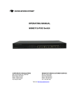
OPERATING MANUAL
ProSwitch 2800M/MR
Managed Modular Fiber and Copper Switch Chassis
CORPORATE HEADQUATERS
MANUFACTURING/CUSTOMER SERVICE
7401 Metro Blvd., Suite 560
Edina, MN 55439
Phone: 800.441.5319
Phone: 952.831.5603
Fax: 952.831.5605
945 37th Avenue, NW
Rochester, MN 55901
Phone: 800.328.2275
Phone: 507.252.1951
Fax: 507.285.1952
Web site: http://www.watersnet.com
TABLE OF CONTENTS
1.0
SPECIFICATIONS ........................................................................................................................... 4
2.0
PACKAGE CONTENTS................................................................................................................... 7
3.0
INTRODUCTION.............................................................................................................................. 7
3.1
3.2
3.3
3.4
3.5
3.6
3.6
3.7
3.8
3.9
3.10
3.11
3.11.1
3.11.2
4.0
ACCESS TO MANAGEMENT FUNCTIONS ................................................................................. 15
4.1
4.2
4.3
4.4
5.0
HARDWARE FEATURES........................................................................................................... 7
SOFTWARE FEATURES ........................................................................................................... 7
UPLINK MODULES.................................................................................................................. 8
REDUNDANT POWER ............................................................................................................. 8
HARDWARE DESCRIPTION ...................................................................................................... 9
LEDS ................................................................................................................................... 9
LEDS ................................................................................................................................. 10
REAR PANEL ....................................................................................................................... 11
INSTALLATION ...................................................................................................................... 11
OPTIONAL SFP MODULES .................................................................................................... 11
POWER ON ......................................................................................................................... 11
SWITCH TOPOLOGY ............................................................................................................. 11
CABLING REQUIREMENTS FOR SFP MODULE.................................................................... 12
CABLE BIT-TIME .............................................................................................................. 12
USING THE RS-232 SERIAL PORT CONNECTION ................................................................... 15
CONFIGURING IP, SUBNET MASK AND DEFAULT GATEWAY ..................................................... 16
CONFIGURING THE SWITCH VIA THE W EB .............................................................................. 16
IP ADDRESS ASSIGNMENT.................................................................................................... 17
WEB BASED MANAGEMENT ...................................................................................................... 22
5.1
5.2
5.3
5.4
5.5
5.6
5.7
5.8
5.8.1
5.8.2
5.8.3
5.8.4
5.9
5.10
5.11
5.12
5.12.1
5.12.2
5.12.3
5.12.4
5.13
5.14
5.15
5.15.1
5.15.2
5.15.3
OVERVIEW OF W EB MANAGEMENT ....................................................................................... 23
SYSTEM INFORMATION ......................................................................................................... 27
IP CONFIGURATION.............................................................................................................. 28
TIME CONFIGURATION.......................................................................................................... 30
ACCOUNT CONFIGURATION .................................................................................................. 32
MANAGEMENT POLICY ......................................................................................................... 33
VIRTUAL STACK ................................................................................................................... 35
PORT CONFIGURATION ........................................................................................................ 37
PORT STATUS...................................................................................................................... 38
PORT CONFIGURATION ........................................................................................................ 42
SIMPLE COUNTER................................................................................................................ 43
DETAIL COUNTER ................................................................................................................ 44
SNMP CONFIGURATION....................................................................................................... 48
DHCP BOOT ....................................................................................................................... 49
IGMP SNOOPING ................................................................................................................ 50
VLANS .............................................................................................................................. 53
VLAN MODE .................................................................................................................. 53
TAG-BASED GROUP ........................................................................................................ 54
PVID.............................................................................................................................. 57
PORT-BASED GROUP....................................................................................................... 58
MAC TABLE ........................................................................................................................ 60
GVRP CONFIGURATION ....................................................................................................... 65
SPANNING TREE CONFIGURATION (STP) CONFIGURATION ..................................................... 69
STP STATUS .................................................................................................................. 69
CONFIGURATION............................................................................................................. 71
STP PORT CONFIGURATION............................................................................................ 73
Waters Network Systems
2800M/MR User’s Manual
Page 2
5.16
5.17
5.18
5.19
5.19.1
5.19.2
5.20
5.21
5.22
5.23
5.24
5.25
5.26
5.27
5.28
6.0
6.1
6.2
7.0
MAINTENANCE ........................................................................................................................... 142
7.1
8.0
EXAMPLES ........................................................................................................................ 142
TROUBLESHOOTING................................................................................................................. 143
8.1
8.2
8.3
9.0
TRUNKING CONFIGURATION ................................................................................................. 75
802.1X CONFIGURATION ...................................................................................................... 79
ALARM CONFIGURATION ...................................................................................................... 88
CONFIGURATION .................................................................................................................. 90
SAVE/RESTORE............................................................................................................... 92
CONFIGURATION FILE ...................................................................................................... 94
SECURITY ........................................................................................................................... 95
BANDWIDTH MANAGEMENT .................................................................................................. 98
QOS (QUALITY OF SERVICE) CONFIGURATION..................................................................... 101
DIAGNOSTICS .................................................................................................................... 112
TFTP SERVER .................................................................................................................. 114
LOG .................................................................................................................................. 115
FIRMWARE UPGRADE......................................................................................................... 116
REBOOT............................................................................................................................ 117
LOGOUT ............................................................................................................................ 118
OPERATION OF CLI MANAGEMENT ..................................................................................... 119
LOGIN ............................................................................................................................... 119
COMMANDS OF CLI ........................................................................................................... 120
BEFORE CALLING FOR ASSISTANCE .................................................................................... 143
RETURN MATERIAL AUTHORIZATION (RMA) PROCEDURE .................................................... 144
SHIPPING AND PACKAGING INFORMATION ............................................................................ 144
WARRANTY ................................................................................................................................ 145
Waters Network Systems
2800M/MR User’s Manual
Page 3
1.0
Specifications
OPERATIONAL CHARACTERISTICS
MAC Address Table: 8K
Switching Mode: Store-and-forward
Memory Buffer Size:
256Kb packet buffer
128Kb control buffer
PERFORMANCE
Non-blocking wire speed
Auto negotiation
Auto-MDIX
Back pressure flow control for half duplex
Flow control for full duplex
Filtering/Forwarding Rate Performance
10Mbps:
14,880 pps
100Mbps:
148,800 pps
1000Mbps:
1,488,000 pps
LED INDICATORS
Per port: Power; Link/Activity; FDX; speed
System LED Power
NETWORK STANDARDS
IEEE 802.3
IEEE 802.3u
IEEE 802.3z
IEEE 802.3ad
IEEE 802.3ab
IEEE 802.3x
IEEE 802.1p/q
IEEE 802.1d/w
IEEE 802.1x
MANAGEMENT FUNCTIONS
Web-based, SNMP, CLI, or Telnet
RMON
RFC1757 group 1, 2, 3 and 9
DHCP client
IGMP snooping function
802.1x port-based authentication
QoS (four levels)
VLANs 4094/Maximum 256 groups
Waters Network Systems
2800M/MR User’s Manual
Page 4
GVRP
Port mirroring
Port trunking
Flow control
Port security
Static MAC address security
TFTP software upgrade capability
EMI/SAFETY COMPLIANCE
FCC Class A & CE Mark Approval
CABLE CONNECTORS
Copper:
RJ45 shielded female ports
10/100Mbps: CAT5 UTP or better
Console Port:
RS232 Cable/DB9 connector
Fiber:
MM FX port: 50/125um, 62.5/125mm
SM FX port: 9/125um
MM SX port: 50/125um, 62.5/125mm
SM LX port: 9/125um
SC, ST and SC connectors
FIBER DISTANCE
100Base-FX
MM: 2km
SM: 20km
1000Base-SX SFPs
MM: 850m
1000Base-LX SFPs
SM: 10km, 1310nm
SM: 40km, 1310nm
POWER SUPPLY
Internal power supply
Input Voltage
100 to 240 VAC, 50 to 60Hz
Power Consumption
45 watts maximum
Waters Network Systems
2800M/MR User’s Manual
Page 5
OPERATING ENVIRONMENT
Ambient Temperature:
32° to 104°F (0° to 40°C)
Storage:
-68° to 158°F (20° to 70°C)
Ambient Humidity:
32% to 104% (non-condensing)
MECHANICAL
Enclosure: Rugged high-strength sheet metal suitable for stand alone or rack mountable
Cooling Method: Fan cooled
PHYSICAL CHARACTERISTICS
Dimensions: 17.4 W x 11 D x 1.75” H (442 x 281 x 44mm)
Weight:
2800M Chassis: 7.5 lbs (3.4 kg)
2800MR Chassis: 10 lbs (4.6 kg)
Copper Module: .61 lbs (.28 kg)
Fiber Module: .75 lbs (3.34 kg)
WARRANTY:
Limited Lifetime
Waters Network Systems
2800M/MR User’s Manual
Page 6
2.0
Package Contents
Examine the shipping container for obvious damage prior to installing this product. Notify the
carrier of any damage that you believe occurred during shipment. Ensure that the items listed
below are included. If an item is missing, please contact your supplier.
3.0
ProSwitch 2800M or MR switch chassis
Modules (sold separately)
Mounting Accessory for (19” rack shelf)
User’s manual
AC power cord
RS-232 Cable
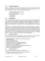
Introduction
The ProSwitch 2800M is a managed modular switch chassis providing outstanding performance
in any network environment requiring a combination of fiber and copper ports. The 2800M has
three module bays for 10/100Base-TX or 100Base-FX (multi or singlemode) 8 port modules. In
addition to the three module bays, the 2800M has two 10/100/1000Base-TX ports and two mini
GBIC slots for 1000Base-SX or 1000Base-LX SFP modules, providing a total of 28 usuable
ports.
The switch can be managed through RS-232 serial port via direct connection or through an
Ethernet port using CLI or Web-based management unit, associated with SNMP agent. With the
SNMP agent, the network administrator can logon the switch to monitor, configure and control
each port’s activity through easy to use menu options. The switch features comprehensive and
useful functions such as QoS (Quality of Service), Spanning Tree, VLAN, Port Trunking,
Bandwidth Control, Port Security, SNMP/RMON, IGMP Snooping capability via the intelligent
software. The switch is suitable for both metro-LAN and office application.
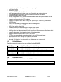
3.1
Hardware Features
The 2800M switch provides the comprehensive features listed below for users to perform
network administration functions efficiently and provide maximum network security.
Conforms to IEEE 802.3, 802.3u, 802.3x, and 802.3ab and 802.3z
256KB packet buffer
Maximum useable ports is 28
Programmable classifier for QoS
8K MAC address and 4K VLAN support (IEEE802.1Q)
Per-port shaping, policing, and broadcast storm control
IEEE802.1Q-in-Q nested VLAN support
Full-duplex flow control (IEEE802.3x) and half-duplex backpressure
Supports online plug/unplug of SFP modules
Extensive front-panel diagnostic LEDs
3.2
Software Features
The following lists management highlights of the 2800M switch:
Supports concisely the status of ports and easily port configuration
Supports per port traffic monitoring counters
Waters Network Systems
2800M/MR User’s Manual
Page 7
Supports a snapshot of the system Information upon login
Port mirror function
Static trunk function
Supports 802.1Q VLAN with 256 entries
User management limited to three users; only first admin can configure device
DHCP broadcasting suppression to avoid network suspensions or crashes
Sends traps events while monitoring
Default configuration can be restored to overwrite the current configuration which can be
used via web browser and CLI
Supports on-line plug/unplug SFP modules
Supports five types of QoS: MAC Priority, 802.1p Priority, IP TOS Priority, and DiffServ
DSCP Priority
Built-in web-based and CLI management and CLI management
Rapid spanning tree (802.1w RSTP)
802.1x port security on a VLAN
SNMP access can be disabled to prevent illegal SNMP access
Support Ingress, Non-Unicast, and Egress bandwidth rating management
The trap events and alarm messages can be transferred via e-mail and mobile phone short
messages service
Supports diagnostics informing administrator of hardware status
Supports external loopback test to check if link is OK
TFTP for firmware upgrade, system log upload, and config file import/export
Remote boot the device through user interface and SNMP
Network time synchronization and daylight saving
Records 120 event logs in main memory and displays on the local console
3.3
Uplink Modules
The following module configurations are available for the 2800M/MR.
2800-8TX
2800-8FXSC
2800-8FXST
2800-8SMSC-20
SFP-1000SXLC
SFP-1000LXLC
SFP-1000SXLC
3.4
8-port 10/100Base-TX module with RJ45 connectors
8-port 100Base-FX MM fiber module with SC connectors
8-port 100Base-FX MM fiber module with ST connectors
8-port 100Base-FX SM (20km, 1310nm) fiber module with SC connectors
1-port 1000Base-SX MM fiber module with LC connector
1-port 1000Base-LX SM (10km) fiber module with LC connector
1-port 1000Base-LX SM (30km) fiber module with LC connector
Redundant Power
Optional redundant power is available for the 2800MR model.
2800-PWR-AC/DC
2800-PWR-DC/DC
Waters Network Systems
1U AC/DC power module
1U DC/DC power module
2800M/MR User’s Manual
Page 8
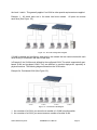
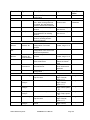
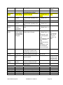
3.5
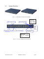
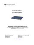
Hardware Description
Figure 3.1 - 2800M Switches with Copper and Fiber Modules
Fiber Port Status: Link
LEDSET Button
LEDSET button is
used to change
the LED display
mode
Power Indication LED
Gigabit
Dual
Media
Port:
SFP/TP
Fast Ethernet Port
Fiber Port Status: ACT/FDX/SPD
LED SET Mode:
ACT/FDX/SPD
RESET Button:
RESET button is used to
reset
the
management
system.
Figure 3.2 - Front View of 2800M Switch with Fiber Modules
Waters Network Systems
2800M/MR User’s Manual
Page 9
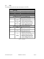
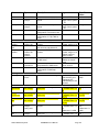
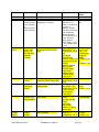
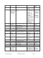
3.6
LEDs
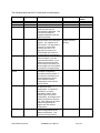
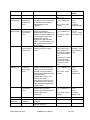
The following table provides the status and description of the LEDs:
LED
CPURUN
POWER
ACT
FDX
SPD
Color
System LED
Green
Green
Green
Green
Green
Function
Blinks when CPU is on and good
Switch is receiving power
Lit when LEDSET set on active mode
Lit when LEDSET set on full-duplex mode
Lit when LEDSET set on speed mode
10/100Mbps Ethernet Port 1 to 8 of 3 Module LED
Port has established a valid link
LNK
Green
Off when there is no connection
a. LEDSET set on ACT (active) mode:
Blinks when traffic is present
Amber
(TP Port 1 to 8 b. LEDSET set on FDX (full-duplex) mode:
of 3 module LED)
Lit when full-duplex mode is active
ACT/FDX/SPD
Blinks when collisions are occurring
Green
(Fiber Port 1 to 8 c. LEDSET set on SPD (speed) mode:
of 3 module LED)
Lit when 100Mbps speed is active
Off when 10Mbps speed is active
10/100/1000Mbps Gigabit TP/Fiber Port 25, 26 LED
Lit when connection with remote device is
LNK
Green
good
Off when there is no connection
Lit when fiber port is active
FB
Green
Off when copper port is active
a. LEDSET set on ACT (active) mode:
Blinks when traffic is present
b. LEDSET set on FDX (full-duplex) mode:
Green
Lit when full-duplex mode is active
ACT/FDX/SPD
Blinks when collisions are occurring
(Port 25,
26 LED)
c. LEDSET set on SPD (speed) mode:
Lit when 1000Mbps speed is active
Off when 10/100Mbps speed is active
Table 3.1 – LED Staus
Waters Network Systems
2800M/MR User’s Manual
Page 10
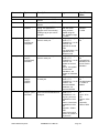
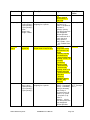
3.7
Rear Panel
Located on the rear panel is the RS-232 DB-9 interface which is used for switch management
configuration.
AC Line 100-240V 50/60 Hz
RS-232 DB-9 Connector
Figure 3.4 - Rear View of 2800M
3.8
Installation
Choose a surface for your switch that is clean, smooth and near a power outlet. Make sure that
there is enough clearance around the switch to allow attachment of cables, power cord and air
circulation.
1. Plug in the power cord into the switch.
2. Install the proper cable for network connection.
3. Plug the power cord into the power source.
3.9
Optional SFP Modules
The SFP modules are hot swappable, so you can plug or unplug the modules before and after
the switch is turned on. If you are installing the optional SFP fiber transceivers, follow these
guidelines:
1.
2.
3.
4.
3.10
Verify that the SFP module is the correct module and conforms to the chassis.
Slide the module along the slot.
Seat the module against the slot socket/connector.
Install the proper cable for network connection.
Power On
Once the switch is on, the bootloader loads the firmware into the memory. It will take about 30
seconds. Once the firmware is loaded, the switch will flash all of the LEDs once and
automatically perform a self test.
3.11
Switch Topology
Theoretically, the switch partitions the collision domain for each port so you may link switches
without limitations. However, network extension (cascading levels & overall diameter) must
follow IEEE 802.3/802.3u/802.3z and other 802.1 series protocol specifications, in which the
limitations are the timing requirement from physical signals defined by 802.3 series specification
of Media Access Control (MAC) and PHY, and layer 2 protocols such as 802.1d, 802.1q, and
LACP.
Waters Network Systems
2800M/MR User’s Manual
Page 11
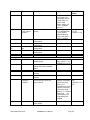
3.11.1
Cabling Requirements for SFP Module
The GSM2800M has four slots for SFP modules. These slots provide fiber connectivity for
Gigabit Ethernet and are optional. The switch supports both multimode and singlemode fiber
connectivity. The following table lists the types of fiber that are supported by the GSM2800M/MR.
Multimode Fiber Cable and Modal Bandwidth
Multimode 62.5/125µm
IEEE 802.3z
Gigabit Ethernet
1000SX 850nm
Modal
Bandwidth
Multimode 50/125µm
Modal
Bandwidth
Distance
Distance
160MHz-Km
220m
400MHz-Km
500m
200MHz-Km
275m
500MHz-Km
550m
Singlemode Fiber 9/125µm
1000BaseLX/LHX/XD/ZX
Singlemode transceiver 1310nm 10Km
Singlemode transceiver 1550nm 30, 50Km
Singlemode
*20km
1000Base-LX
Singlemode
(BIDI LC)
Singlemode
*20km
TX (Transmit)
1310nm
RX (Receive)
1550nm
TX (Transmit)
1550nm
RX (Receive)
1310nm
Table 3.2 – Fiber Cable
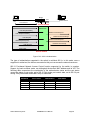
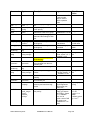
3.11.2
Cable Bit-Time
The following table describes the cable and devices’ bit-time delay (round trip):
1000Base-X TP, Fiber
100Base-TX TP
Round trip Delay: 4096
100Base-FX Fiber
Round trip Delay: 512
CAT5
11.12/m
CAT5
Fiber
10.10/m
TP to fiber converter: 56
Bit time unit: 1ns (1sec./1000 Mega bit)
1.12/m
Fiber Cable:
1.0/m
Bit time unit: 0.01µs (1sec./100 Mega bit)
Table 3.3 – Cable Bit-Time
Sum up all elements’ bit-time delay and the overall bit-time delay of wires/devices must be
within Round Trip Delay (bit times) in a half-duplex network segment (collision domain). This will
not be applied for full duplex operation. You may use the TP-Fiber module to extend the TP
node distance over fiber optic and provide the long haul connection.
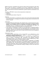
A hierarchical network with minimum levels of switching may reduce the timing delay between
server and client station. Basically, with this approach, it will minimize the number of switches in
any one path; will lower the possibility of network loop and will improve network efficiency. If
more than two switches are connected in the same network, select one switch as Level 1 switch
and connect all other switches to it at Level 2. It is recommended to connect the Server/Host to
Waters Network Systems
2800M/MR User’s Manual
Page 12
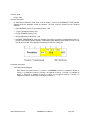
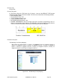
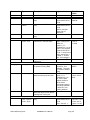
the Level 1 switch. This generally applies if no VLAN or other special requirements are applied.
Example 1: All switch ports are in the same local area network.
each other (See Figure 3.4).
All ports can access
Figure 3.4 - No VLAN Configuration Diagram
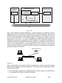
If VLAN is enabled and configured, each node in the network that can communicate with each
other directly is contained in the same VLAN area.
In Example 2, the VLAN area is defined by the configured VLAN. The switch supports both portbased VLAN and tag-based VLAN. They are different in practical deployment, especially in
physical locations. The following diagram shows how the VLAN works.
Example 2a: Port-based VLAN (See Figure 3.5).
Figure 3.5 - Port-based VLAN Diagram
1. As a member of a VLAN, you cannot be a member of a VLAN in another switch.
2. As a member of a VLAN, you cannot access a member of another VLAN.
Waters Network Systems
2800M/MR User’s Manual
Page 13
3. The switch
at one switch.
manager
has
to
assign
different
names
for
each
VLAN
group
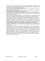
Case 2b: Port-based VLAN (See Figure 3.6)
Figure 3.6 - Port-based VLAN Diagram
This is an example of how VLANs can be set up between two switches.
1. VLAN1 members cannot access VLAN2, VLAN3 and VLAN4 members.
2. VLAN2 members cannot access VLAN1 and VLAN3 members, but they can access VLAN4
members.
3. VLAN3 members cannot access VLAN1, VLAN2 and VLAN4.
4. VLAN4 members cannot access VLAN1 and VLAN3 members, but they can access VLAN2
members.
Example 3a: The same VLAN members can be at different switches with the same VID
(See Figure 3.7).
Waters Network Systems
2800M/MR User’s Manual
Page 14
Figure 3.7 - Attribute-based VLAN Diagram
4.0
Access to Management Functions
There are three ways to access switch management functions:
1. RS-232 serial port connection (CLI)
2. Telnet
3. Web
Note: Before accessing management functions through Telnet or the Web, you must modify the
IP address, subnet mask, default gateway and DNS through the RS-232 connection.
4.1
Using the RS-232 Serial Port Connection
To configure the switch via the RS-232 serial port connection, follow these steps:
1. Connect the serial cable included with your switch to your workstation.
2. Connect the serial cable to console connector on the back of your switch.
3. Run the terminal emulator (Example: HyperTerminal) using the following settings.
a. Baud rate (bits per second):
115200
b. Data bits:
8
c. Parity:
N
d. Stop bits:
1
e. Flow control:
None
4. When you complete the connection, press the Enter key.
5. Turn on the switch.
6. The default login is:
a. Username = admin
b. Password = admin
Waters Network Systems
2800M/MR User’s Manual
Page 15
4.2
Configuring IP, Subnet Mask and Default Gateway
The default settings for your switch are listed in the following table:
Default Value
IP Address
Subnet
Default Gateway
GSM2800M/MR
192.168.1.1
255.255.255.0
192.168.1.254
Table 4-1
You may either change the IP address of the switch or change the IP address of your
workstation. To change the IP address of the switch, via the console connection, you will have
to use the CLI command listed below. A complete list of CLI commands is in Section 6.0 of this
manual.
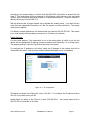
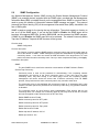
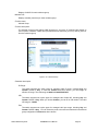
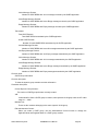
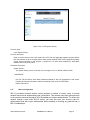
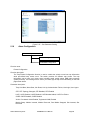
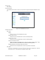
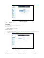
1. Once you have logged into the switch, you will see the following screen.
Figure 4.1 – Login screen
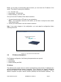
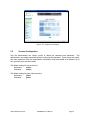
4.3
Configuring the Switch via the Web
You can configure and monitor the switch through:
CLI
Web browser
SNMP manager. The user interface for SNMP is not covered at this time.
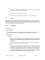
Assign an IP address,
For example:
IP = 192.168.1.100
Subnet Mask = 255.255.255.0
Default Gateway = 192.168.1.254
Ethernet LAN
Figure 4.2 – Ethernet Port Connection
Waters Network Systems
2800M/MR User’s Manual
Page 16
Before you are able to communicate with the switch, you must know the IP address of the
switch. The default IP setting for the 2800M is:
IP = 192.168.1.100
Subnet Mask = 255.255.255.0
Default Gateway = 192.168.1.253
Once you know the IP address, follow these instructions:
1. Connect the switch with a UTP cable to your workstations.
Note: If the workstation connects to the switch, you will have to setup the same subnet
mask between them.
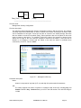
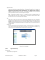
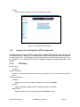
2. Access your web browser or use the console connection.
Note: If you make changes to the configuration, you must save the configuration before
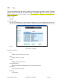
rebooting the switch.
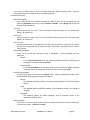
Figure 4.3 - Login Screen via a Web browser
4.4
IP Address Assignment
For IP address configuration, the following three parameters are required:
IP address
Subnet Mask
Default Gateway and DNS.
IP Address:
The address of the network device is used for internetworking communication. IP addresses are
split into predefined address classes or categories. This is referred to as “classful” addressing
because the address is spilt into three predefined classes, groupings or categories. Each IP
address comprises two parts: network identifier (address) and host identifier (address). The
Waters Network Systems
2800M/MR User’s Manual
Page 17
network identifier identifies the network on which the host resides, while the host identifier
identifies the particular host on the given network. The host identifier must be unique in the
same LAN. Each class has its own network range between the network identifier and host
identifier in the 32 bits address. IP address is known as IPv4.
32 bits
Network identifier
Host identifier
With “classful” addressing, the IP address is divided into three classes: class A, class B and
class C. The rest of IP addresses are for multicast and broadcast. The bit length of the network
prefix is the same as that of the subnet mask and is denoted as IP address/X, for example,
192.168.1.0/24. Each class has its address range described below.
Class A:
Address is less than 126.255.255.255. There are a total of 126 networks can be defined
because the address 0.0.0.0 is reserved for default route and 127.0.0.0/8 is reserved for
loopback function.
Bit # 0 1
78
31
0
Network address
Host address
Class B:
IP address range between 128.0.0.0 and 191.255.255.255. Each class B network has a 16-bit
network prefix followed 16-bit host address. There are 16,384 (2^14)/16 networks able to be
defined with a maximum of 65534 (2^16 –2) hosts per network.
Bit #
01 2
15 16
31
10
Network address
Waters Network Systems
Host address
2800M/MR User’s Manual
Page 18
Class C:
IP address range between 192.0.0.0 and 223.255.255.255. Each class C network has a 24-bit
network prefix followed 8-bit host address. There are 2,097,152 (2^21)/24 networks able to be
defined with a maximum of 254 (2^8 –2) hosts per network.
Bit # 0 1 2 3
23 24
31
110
Network address
Host
Class D and E:
Class D is a class with first 4 MSB (most significance bit) set to 1-1-1-0 and is used for IP
Multicast. See also RFC 1112. Class E is a class with first 4 MSB set to 1-1-1-1 and is used for
IP broadcast.
According to IANA (internet assigned numbers authority), there are three specific IP address
blocks reserved and able to be used for extending internal networks. This is referred to as
Private IP address and listed below:
Class A
Class B
Class C
10.0.0.0 --- 10.255.255.255
172.16.0.0 --- 172.31.255.255
192.168.0.0 --- 192.168.255.255
Please refer to RFC 1597 and RFC 1466 for more information.
Subnet mask:
Subnet mask is the sub-division of a class-based network or a CIDR block. The subnet is used
to determine how to split an IP address to the network prefix and the host address in bitwise
basis. It is designed to utilize the IP address more efficiently and make it easier to manage IP
networks.
For a class B network, 128.1.2.3, the subnet mask 255.255.0.0 in default, in which the first two
bytes are all 1s. This means more than 60 thousands of nodes in flat IP address will be at the
same network. This is too large to manage practically. Now if we divide it into a smaller network
by extending network prefix from 16 bits to, say 24 bits, its third byte is used to subnet this class
B network. Now it has a subnet mask 255.255.255.0, in which each bit of the first three bytes is
1. It’s now clear that the first two bytes is used to identify the class B network, the third byte is
used to identify the subnet within this class B network and, of course, the last byte is the host
number.
Not all IP addresses are available in the sub-netted network. Two special addresses are
reserved. They are the addresses with all zero’s and all one’s. For example, an IP address
128.1.2.128, what will the reserved IP address look like? All 0s mean the network itself, and all
1s mean IP broadcast.
Waters Network Systems
2800M/MR User’s Manual
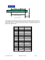
Page 19
128.1.2.128/25
Network
Subne
10000000.00000001.00000010.1 0000000
25 bits
All 0s = 128.1.2.128
1 0000000
1 1111111
All 1s= 128.1.2.255
In this diagram, the subnet mask with 25-bit long, 255.255.255.128, contains 126 members in
the sub-netted network. The length of network prefix equals the number of the bit with 1s in that
subnet mask. With this, you can easily count the number of IP addresses matched. The
following table shows the result.
Prefix Length No. of IP matched No. of Addressable IP
/32
1
-
/31
2
-
/30
4
2
/29
8
6
/28
16
14
/27
32
30
/26
64
62
/25
128
126
/24
256
254
/23
512
510
/22
1024
1022
/21
2048
2046
/20
4096
4094
/19
8192
8190
/18
16384
16382
/17
32768
32766
/16
65536
65534
Table 4.2
Waters Network Systems
2800M/MR User’s Manual
Page 20
According to the scheme above, a subnet mask 255.255.255.0 will partition a network with the
class C. This means there will be a maximum of 254 effective nodes existing in this sub-netted
network and is considered a physical network in an autonomous network. It owns a network IP
address which may look like 168.1.2.0.
With the subnet mask, a bigger network can be divided into smaller pieces. If you want to have
more than two independent networks in a LAN, the network must be partitioned. The subnet
mask must be applied.
For different network applications, the subnet mask may look like 255.255.255.240. This means
it is a small network accommodating a maximum of 15 nodes in the network.
Default Gateway:
For the routed packets, if the destination is not in the routing table, all traffic is put into the
device with the designated IP address, known as default router. Basically, it is a routing policy.
The gateway setting is used for Trap Events Host only in the switch.
For assigning an IP address to the switch, check the IP address of the network that will be
connected to the switch. Use the same network address and append your host address.
Figure 4.4 – IP Configuration
IP Address: as shown in the Figure 4.4, enter “192.168.1.1”, for instance. An IP address such as
192.168.1.x must be set on your PC.
Subnet Mask: as shown in the Figure 4.4, enter “255.255.255.0”. Any subnet mask such as
255.255.255.x is allowable in this case.
Waters Network Systems
2800M/MR User’s Manual
Page 21
DNS:
The Domain Name Server translates the human readable machine name to IP address. Every
machine on the Internet has a unique IP address. A server generally has a static IP address. To
connect to a server, the client needs to know the IP of the server. However, generally the name
is used to connect to the server. Thus, the switch DNS client program (such as a browser) will
ask the DNS to resolve the IP address of the named server.
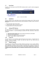
5.0
Web Based Management
This section illustrates the configuration and management of the GSM switch through a web
interface. Management through the web interface allows you to easily access and monitor the
switch through any port.
The default values of the managed switch are listed in the table below:
IP Address
192.168.1.1
Subnet Mask
255.255.255.0
Default Gateway 192.168.1.253
Username
admin
Password
admin
Table 5.1
Once the 2800M switch has been configured via the switch’s serial interface, you are ready to
use the web management function. You must be connected to the switch via one of the
Ethernet ports.
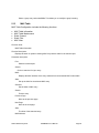
Access your web browser, and type in http://192.168.1.1 (or the assigned IP address) in the
address field. The login screen will be displayed. The default username and password are both
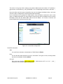
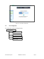
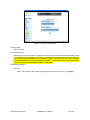
“admin”. Click on the Login button. The login process now is completed.
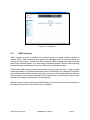
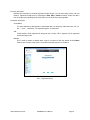
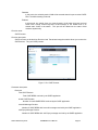
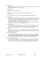
If you forget the password, click the link Forget Password in WebUI (See Figure 5.1) or input
“Ctrl+Z” in from the CLI’s login screen. The system will display a serial number. Write down this
serial number and contact your vendor. The vendor will provide you with a temporary password.
Use this new password as ID and Password to temporarily login. This new password is a
limited use password and will only allow you log into the system one time. Therefore, modify
your password one you login to the system.
The switch supports a simple user management function allowing only one administrator to
configure the system at a time. If there are two or more users using administrator’s identity, the
switch will allow the one who logins first to configure the system. The rest of users, even with
administrator’s identity, can only monitor the system. Without administrator’s identity, you can
only monitor the system.
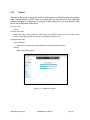
A maximum of three users are able to login simultaneously in the switch. To optimize the display
effect, we recommend you use Microsoft IE 6.0 or Firefox V1.00 or above as your web browser.
Waters Network Systems
2800M/MR User’s Manual
Page 22
Figure 5.1 – Login Screen
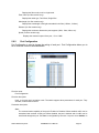
5.1
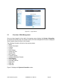
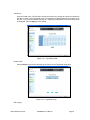
Overview of Web Management
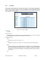
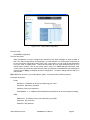
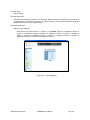
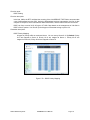
Once you have logged into the switch, the opening screen displays the System Information.
On the left side of the screen, the function tree for all of the management functions is displayed.
We will explore these functions in this chapter.
The following information is listed on the opening screen:
Model
System Description
Location
Contact
Device Name
System Up Time
Current Time
BIOS Version
Firmware Version
Hardware-Mechanical Version
Serial Number
Host IP Address
Host MAC Address
Device Port
RAM Size
Flash Size
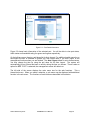
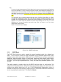
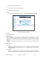
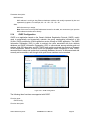
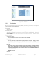
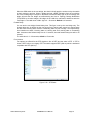
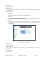
Figure 5.2 displays the System Information screen.
Waters Network Systems
2800M/MR User’s Manual
Page 23
Figure 5.2 – System Information
The top of the screen displays the front panel of the switch. The linked ports will be displayed in
green and the ports that are not connected will be dark. The optional modules will display a
cover plate if no module exists and will show a module if a module is present. The image of
module depends on the installed module. If the module port is not connected, the port be dark
and, if linked, green.
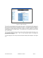
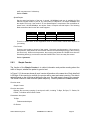
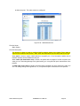
The front panel displayed at the top of the screen provides clicking functions that allow you to
view information about the switch. This is a very convenient function for browsing the
information for a single port.
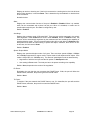
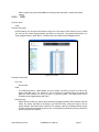
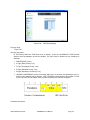
To view a single port, click on the port and an information window will be displayed. (See Figure
5.3)
Waters Network Systems
2800M/MR User’s Manual
Page 24
Figure 5.3 – Port Detail Information
Figure 5.3 shows basic information of the selected port. You will be able to view port status,
traffic status and bandwidth rating for egress and ingress respectively.
On the left-top corner, there is a pull-down list for Auto Logout. For additional switch security, an
auto-logout function is available to protect you from illegal users if you don’t logout of the
management functions when you are finished. The Auto Logout default is set to three minutes.
You may change the time by using the pull down list for Auto Logout. The system will
automatically log out if there has been no activity during the time you choose. There is also an
option for OFF. If OFF is selected, the management screen will remain on.
The left side of the screen displays the main menu tree for the web functions. This a
hierarchical menu. When you make a selection, a sub menu may be displayed with additional
function in the sub menu. The functions of each folder are described in this section.
Waters Network Systems
2800M/MR User’s Manual
Page 25
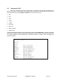
The following list is the full function tree for web user interface.
Root
System
Port
SNMP
DNCP Boot
IGMP Snooping
VLAN
MAC Table
GVRP
STP
Trunk
802.1X
Alarm
Configuration
Security
Bandwidth
QoS
Diagnostics
TFTP Server
Log
Firmware Upgrade
Reboot
Logout
Waters Network Systems
2800M/MR User’s Manual
Page 26
5.2
System Information
Function name:
System Information
Function description:
Show the basic system information.
Parameter description:
Model name:
The model name of this device.
System description:
Describes the device. “3 Slot, 24 FE + 2 GbE Dual Media L2 Managed Switch”.
Location:
The location where this switch is being used. User-defined.
Contact:
For the purpose of managing and maintaining the device, enter the contact person and phone
to be used for help. You can configure this parameter through the device’s user interface or
SNMP.
Device name:
The name of the switch. User-defined. Default is CES2326B.
System up time:
The time accumulated since this switch was powered up. The format is day, hour, minute and
second.
Current time:
Show the system time of the switch. The format: day of week, month, day, hours:minutes:
seconds, year. For instance, Wed, Apr. 23, 12:10:10, 2004.
BIOS version:
The version of the BIOS.
Firmware version:
The firmware version.
Hardware-Mechanical version:
The version of Hardware and Mechanical. The figure before the hyphen is the version of
electronic hardware; the one after the hyphen is the version of mechanical.
Serial number:
The serial number is assigned by the manufacturer.
Host IP address:
The IP address of the switch.
Host MAC address:
Waters Network Systems
2800M/MR User’s Manual
Page 27
It is the Ethernet MAC address of the management agent in this switch.
Device Port:
Show all types and numbers of the port in the switch.
RAM size:
The size of the DRAM in this switch.
Flash size:
The size of the flash memory in this switch.
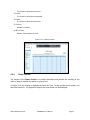
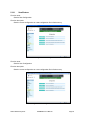
5.3
IP Configuration
IP configuration is one of the most important configurations in the switch. Without the proper
setting, the network manager will not be able to manage or view the device. The switch supports
both manual IP address setting and automatic IP address setting via DHCP server. When IP
address is changed, you must reboot the switch so the setting takes effect and uses the new IP
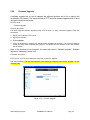
for management access.
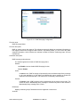
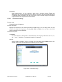
Figure 5.4 - IP Address Configuration
Function name:
IP Configuration
Function description:
Set IP address, subnet mask, default gateway and DNS for the switch.
Parameter description:
DHCP Setting:
DHCP is the abbreviation of Dynamic Host Configuration Protocol. DHCP is disabled by default.
In this menu, you may enable or disable DHCP.
The switch supports DHCP client used to get an IP address automatically if you set this function
“Enable”. When enabled, the switch will issue the request to the DHCP server to get an IP
address. If the DHCP server is down or does not exist, the switch will issue the request and
notify you that the IP address is being requested until the DHCP server is up. Before getting an
Waters Network Systems
2800M/MR User’s Manual
Page 28
IP address from DHCP server, the device will stop the booting process. If the field is set to
“Disable”, you will have to input the IP address manually. For more details about IP address and
DHCP, refer to Section 4.4 - IP Address Assignment.
Default: Disabled
IP address:
Users can configure the IP settings and enter new values if the DHCP function is set to Disable.
Click the Apply button to update.
When DHCP is disabled, the default is 192.168.1.1.
If DHCP is enabled, this field is completed by the DHCP server and the user will not be able to
manually set IP addresses.
Subnet mask:
The purpose of the subnet mask is to retrieve more network addresses. An IP device in a
network must own its IP address, composed of network address and host address; otherwise
communication with other devices cannot be made. The network classes A, B, and C are all too
large to fit for almost all networks, so the subnet mask is introduced to solve this problem. A
subnet mask uses some bits from the host address and makes an IP address look at the
network address, subnet mask number and host address. It is shown in the following figure.
This reduces the total of IP numbers that a network is able to support by the power of 2.
32 bits
Network ID
Host ID
Network ID
Host ID
Subnet number
The subnet mask is used to set the subnet mask value, which should be the same value as that
of the other devices resided in the same network it attaches.
Default: 255.255.255.0
Default gateway:
Set an IP address for a gateway to handle those packets that do not meet the routing rules
predefined in the device. If a packet does not meet the criteria for other pre-defined path, it must
be forwarded to a default router on a default path. This means any packet with undefined IP
address in the routing table will be sent to this device unconditionally.
Default: 192.168.1.253
DNS:
The Domain Name Server is used to serve the translation between IP address and name
address. The switch supports DNS client function to re-route the mnemonic name address to
DNS server to get its associated IP address for accessing Internet. You can specify a DNS IP
address for the switch. The switch can translate a mnemonic name address into an IP address.
There are two ways to specify the IP address of DNS. One is fixed mode, which manually
specifies its IP address, the other is dynamic mode, which is assigned by DHCP server while
Waters Network Systems
2800M/MR User’s Manual
Page 29
DHCP is enabled. DNS can help you easily remember the mnemonic address name with the
meaningful words in it. No assignment of DNS address is made by default.
Default: 0.0.0.0
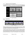
5.4
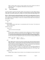
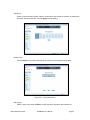
Time Configuration
The switch provides a manual and automatic method to set the system time via NTP. Manual setting is
simple. Input “Year”, “Month”, “Day”, “Hour”, “Minute” and “Second” within the valid value range indicated
in each item. If you input an invalid value, for example, 61 in minute, the switch will clamp the figure to 59.
NTP is a well-known protocol used to synchronize the system time of the switch system time over a
network. NTP, an internet draft standard formalized in RFC 1305, has been adopted on the system is
version 3 protocol. The switch provides four built-in NTP server IP addresses residing in the Internet and
an user-defined NTP server IP address. The time zone is Greenwich-centered which uses the expression
form of GMT+/- xx hours.
Function name:
Time
Function description:
Set the system time by manual input or by synchronizing from Time servers. The function also
supports daylight saving.
Parameter description:
Current Time:
Show the current time of the system.
Manual:
Use this function to adjust the time manually. Enter the valid figures in the fields of Year, Month,
Day, Hour, Minute and Second respectively and press the Apply button. The time is adjusted.
The valid figures for the parameter Year, Month, Day, Hour, Minute and Second are >=2000, 112, 1-31, 0-23, 0-59 and 0-59 respectively. Input the wrong figure and press the Apply button,
the device will reject the time adjustment request. There is no time zone setting in Manual mode.
Default: Year = 2000,
Hour = 0,
Month = 1,
Day = 1
Minute = 0, Second = 0
NTP:
NTP is Network Time Protocol and is used to synchronize the network time based Greenwich
Mean Time (GMT). If used in the NTP mode and have selected a built-in NTP time server or
manually specify an user-defined NTP server as well as Time Zone, the switch will synchronize
the time shortly after pressing the Apply button. Though it synchronizes the time automatically,
NTP does not update the time periodically without user’s processing.
Time Zone is an offset time off GMT. To set, select the time zone first and then perform time
synchronization via NTP. The switch will combine this time zone and updated NTP time to
arrive at the local time. The switch supports configurable time zone from –12 to +13 step 1 hour.
Default Time zone: +8 Hrs.
Daylight Saving:
Daylight saving is adopted in some countries. If set, it will adjust the time lag or advance in unit
Waters Network Systems
2800M/MR User’s Manual
Page 30
of hours, according to the starting date and the ending date. For example, if you set the daylight
saving to be one hour, when the time passes over the starting time, the system time will be
increased one hour after one minute at the time since it passed over. And when the time passes
over the ending time, the system time will be decreased one hour after one minute at the time
since it passed over.
The switch supports valid configurable daylight saving time is –5 ~ +5 step one hour. The zero
for this parameter means it need not have to adjust current time, equivalent to in-act daylight
saving. You don’t have to set the starting/ending date as well. If you set daylight saving to be
non-zero, you have to set the starting/ending date as well; otherwise, the daylight saving
function will not be activated.
Default for Daylight Saving: 0.
The following parameters are configurable for the function Daylight Saving and described in
detail.
Daylight Saving Start :
This is used to set when to start performing the daylight saving time.
Month:
Range is 1 ~ 12.
Default: 1
Day:
Range is 1 ~ 31.
Default: 1
Hour:
Range is 0 ~ 23.
Default: 0
Daylight Saving End :
This is used to set when to stop performing the daylight saving time.
Month:
Range is 1 ~ 12.
Default: 1
Day:
Range is 1 ~ 31.
Default: 1
Hour:
Range is 0 ~ 23.
Default: 0
Waters Network Systems
2800M/MR User’s Manual
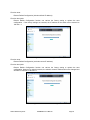
Page 31
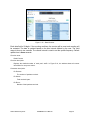
Figure 5.5 – System Time Setting
5.5
Account Configuration
Only the administrator can create, modify or delete the username and password. The
administrator can modify passwords without confirming the password. Guest users can modify
their own password. Only one administrator is allowed to exist and unable to be deleted. Up to
four guest accounts can be created.
The default setting for user account is:
Username:
admin
Password:
admin
The default setting for guest user account is:
Username:
guest
Password:
guest
Waters Network Systems
2800M/MR User’s Manual
Page 32
Figure 5.6 – Account Configuration
5.6
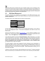
Management Policy
Through the management security configuration, the manager can perform the setup to control the switch
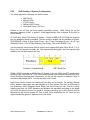
and limit user to access the switch. The following rules are provided for the management of the switch:
Rule 1: If no lists exists, all connections are accepted.
Accept
__________________________________________________
Rule 2: If “accept lists” exists, all connections will be denied except the connection inside the accepting
range.
Accept
Deny
Accept
Deny
Accept
__________________________________________________
Rule 3: If “deny lists” exists, all connections will be denied.
Deny
Accept
Deny
Accept Deny
__________________________________________________
Rule 4: If both “accept and deny” lists exist, all connections will be denied except the connection inside
the accepting range.
Accept
Deny
Deny
Deny
Accept
__________________________________________________
Rule 5: If both “accept and deny” lists exist, all connections will be denied except the connection inside
of accepting range and NOT inside the denying range at the same time.
Waters Network Systems
2800M/MR User’s Manual
Page 33
Accept
Accept
Deny
Deny| Acc | Deny
| Acc
| Deny
__________________________________________________
Function name:
Management Security Configuration
Function description:
The switch provides a Management Security Configuration function. With this function, the manager
can easily control the mode that the is used to connect to the switch. According to the mode, users
can be classified into two types: Those who are able to connect to the switch (Accept) and those
who are unable to connect to the switch (Deny). Some restrictions also can be placed on the mode
used to connect to the switch. For example, VLAN VID is able to be accepted or denied by the
switch, the IP range of the user could be accepted or denied by the switch, a user port can be
allowed or not allowed to connect with the switch, or the way the switch is controlled when
connected by via HTTP, Telnet or SNMP.
Figure 5.7 – Management Security
Parameter description:
Name:
A name is composed of any letter (A-Z, a-z) and digit (0-9) with maximal 8 characters.
VID:
The switch supports two kinds of options for managed valid VLAN VID, including Any and
Custom. Default is Any. Custom allows you to fill in the VID number. The valid VID range is
1~4094.
Waters Network Systems
2800M/MR User’s Manual
Page 34
IP Range:
The switch supports two kinds of options for managed valid IP Range, including Any and
Custom. Default is Any. Custom allows you to assign an effective IP range. The valid range is
0.0.0.0~255.255.255.255.
Incoming Port:
The switch supports two kinds of options for managed valid Port Range, including Any and
Custom. The default is Any. Custom allows you select the ports that should be used and the
ports that should be restricted in the management security configuration.
Access Type:
The switch supports two options for managed valid Access Type, including Any and Custom. The
default is Any. Http, Telnet and SNMP are three ways to access and manage the switch if
Custom has been chosen.
Action:
The switch supports two options for managed valid Action Type, including Deny and Accept. The
default is Deny. Deny restricts access to switch management. Accept provides the authority to
manage the switch.
Edit/Create:
A new entry of Management Security Configuration can be created after the parameters as
mentioned above had been setup and then press <Edit/Create> button. Of course, the existed
entry also can be modified by pressing this button.
Delete:
Remove the existed entry of Management Security Configuration from the management
security table.
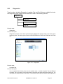
5.7
Virtual Stack
Function name:
Virtual Stack
Function description:
Virtual Stack Management (VSM) provides a simple centralized management function capable of
managing up to sixteen (16) switches. Through the proper configuration of the VSM function,
switches in the same LAN will be grouped automatically. One switch will be the master device, and
the others in the group will become the slave devices.
It is not necessary to remember the address of all the VSM devices; the manager is capable of
managing the network and all devices within the VSM stack.
VSM is only available using Web UI. With one switch functioning as the master, two rows of buttons
for the group devices will appear on the top of the Web UI. By pressing these buttons, users will be
allowed to connect to the Web UI of the devices of the group in the same window without the logging
into these devices.
The top-left button is only for the Master device (Figure 5.8). The background color of the button you
press will be changed to represent that the device is under your management.
Note: It will remove the grouping temporarily if you login the switch via the console.
Waters Network Systems
2800M/MR User’s Manual
Page 35
The device of the group will be shown as the station address (the last number of IP Address) +
device name on the button (e.g. 196_CES2326B). If no corresponding device exists, it will show ”---“.
Once the devices join the group successfully, they can be managed via Master device, and users
will not be able to manage them via telnet/console/web individually.
Up to 16 devices can be grouped for VSM; however, only one Master is allowed to exist in each
group. For Master redundancy, you may configure more than two devices as Master device; however,
the Master device with the smaller MAC value will be the Master. All of these 16 devices can
become Master device and back up each other.
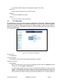
Figure 5.8 – Virtual Stack Configuration
Parameter description:
State:
It is used for the activation or de-activation of VSM. Default is Enable.
Role:
The role that the switch would like to play in virtual stack. Two types of roles, including master
and slave are available. Default is Master.
Group ID:
GID is the group identifier which signs for VSM. Valid letters are A-Z, a-z, 0-9, “-“, and “_”
characters. The maximal length is 15 characters.
Waters Network Systems
2800M/MR User’s Manual
Page 36
Figure 5.9 – Virtual Stack Configuration
5.8
Port Configuration
Port configuration includes the following functions:
Port Configuration
Status
Configuration
Simple Counter
Detail Counter
Waters Network Systems
2800M/MR User’s Manual
Page 37
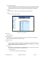
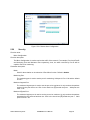
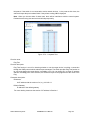
5.8.1
Port Status
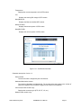
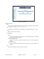
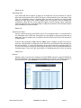
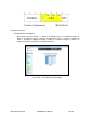
The port status function gathers the current status for all ports. The information is displayed by
the order of port number, link status, port state, auto-negotiation status, speed/duplex and flow
control. If a fiber module is installed in one or both of the slots, the current status for those ports
will be displayed. See Figure 5.10
Figure 5.10 – Current Port Status
Function name:
Port Status
Function Description:
Port status reports the current status of all ports in the switch. The screen will be automatically
refreshed approximately every five seconds as port parameters change.
Parameter Description:
Slot No.:
Displays the port number. The number is 1 – 3.
Port No.:
Displays the port number. The number is 1 -26. Both Port 25 and 26 are optional modules.
Media:
Shows the media type used in all ports. Ports 25-26 are optional modules, which support either
fiber or UTP media with either Gigabit Ethernet or Fast Ethernet. They may have different
media types and speed. Since the fiber port could be multimode or singlemode, the information
will be based on the actual media installed in the switch with reference to connector, distance,
fiber mode, etc.
Link:
Waters Network Systems
2800M/MR User’s Manual
Page 38
Displays an active or inactive port. If the link is connected to a working device, the link will show
that is it Up; otherwise, it will show Down. This is determined by the hardware on both devices
of the connection.
No default value.
State:
Displays the communication function of the port is Enabled or Disabled. When it is enabled,
traffic can be transmitted and received via this port. When it is disabled, no traffic can be
transferred through this port. Port State is configured by user.
Default: Enabled.
Auto Nego:
Displays the exchange mode of Ethernet MAC. There are two modes supported in the switch;
Auto-negotiation mode Enabled and forced mode Disabled. When in Enabled mode, this
function will be automatically negotiated by the hardware itself and exchange the capability of
speed and duplex mode. The best communication mode will be used. When in Disabled mode,
both parties must have the same setting of speed and duplex, otherwise, there will be no link.
In this case, the link result is Down.
Default: Enabled
Speed / Duplex Mode:
Displays the speed and duplex mode of all ports. There are three speeds 10Mbps, 100Mbps
and 1000Mbps supported for copper media. Duplex mode is half duplex and full duplex. If the
media is 1Gbps fiber, it is 1000Mbps only. The status of speed/duplex mode is determined by:
Negotiation of both the local port and the link partner in Auto Speed mode
User setting in Force mode. The local port has to be preset according to its capability.
Default: None, depends on the result of the negotiation.
Rx Pause:
Rx displays the way that the port processes the PAUSE frame. If On, the port will follow the
PAUSE frame; otherwise, the port will ignore the PAUSE frame.
Default: None
Tx Pause:
Tx decides if the port transmits the PAUSE frame or not. If it shows On, the port will send the
PAUSE frame; otherwise, the port will not send the PAUSE frame.
Default: None
Waters Network Systems
2800M/MR User’s Manual
Page 39
Figure 5.11 – Port Detail
Parameter description of Port 25 and Port 26:
Connector Type:
Displays connector type (UTP, SC, ST, LC, etc.)
Fiber Type:
Display the fiber mode (multi or singlemode)
Tx Central Wavelength:
Displays the fiber optical transmitting central wavelength (850nm, 1310nm, 1550nm, etc.)
Baud Rate:
Displays the maximum baud rate of the fiber module supported, for instance (10M, 100M,
1G, etc.)
Vendor OUI:
Displays the Manufacturer's OUI code which is assigned by IEEE.
Vendor Name:
Displays the company name of the module manufacturer.
Vendor P/N:
Displays the product name of the module manufacturer.
Vendor Rev (Revision):
Displays the module revision.
Vendor SN (Serial Number):
Displays the serial number assigned by the manufacturer.
Date Code:
Displays the date the SFP module was made.
Waters Network Systems
2800M/MR User’s Manual
Page 40
Temperature:
Displays the current temperature of the SFP module.
Vcc:
Displays the working DC voltage of SFP module.
Mon1(Bias) mA:
Displays the Bias the installed SFP module.
Mon2(TX PWR):
Displays the transmit power of SFP module.
Mon3(RX PWR):
Displays the receiver power of SFP module.
Figure 5.12 – Slot Detail Information
Parameter description of slots 1-3:
Serial number:
The serial number is assigned by the manufacturer.
Hardware-Mechanical version:
The version of Hardware and Mechanical. The number before the hyphen is the version of
electronic hardware; the one after the hyphen is the version of mechanical.
Connector(for fiber module only):
Displays the connector type (UTP, SC, ST, LC, etc.)
Mode(for fiber module only):
Waters Network Systems
2800M/MR User’s Manual
Page 41
Displays the fiber mode, multi or singlemode.
Fiber Cable (for fiber module only):
Displays the cable type, Two Wires, Single Wire.
Wavelength (for fiber module only):
Displays the wavelength of the light transmitted in the fiber ( 850nm, 1310nm).
Distance (for fiber module only):
Displays the maximum distance the port supports (100m, 10km, 20km, etc).
Speed (for fiber module only):
Displays the maximum speed of the port, 1G or 100M.
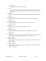
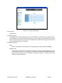
5.8.2
Port Configuration
Port Configuration is used to change the setting of each port. Port Configuration allows you to
set or reset the functions described below.
Figure 5.13 – Port Configuration
Function name:
Port Configuration
Function description:
Used to set each port’s operation mode. The switch supports three parameters for each port. They
are state, mode and flow control.
Parameter description:
State:
The communication capability of the port is Enabled or Disabled. When enabled, traffic can be
transmitted and received via this port. When disabled, the port is blocked and no traffic can be
transferred through this port. Port State is configurable by the user. If a port is set to disable, no
Waters Network Systems
2800M/MR User’s Manual
Page 42
traffic can pass even if it linked up.
Default: Enable.
Speed/Duplex:
Set the speed and duplex of the port. In speed, 10/100Mbps baud rate is available for Fast
Ethernet, Gigabit module in port 25, 26. If the media is 1Gbps fiber, it is always 1000Mbps and
the duplex is full only. If the media is TP, the Speed/Duplex is comprised of the combination of
speed mode, 10/100/1000Mbps, and duplex mode, full duplex and half duplex. The following
table summarized the function the media supports.
Media type
100M TP
1000M TP
1000M Fiber
NWay
ON/OFF
ON/OFF
ON/OFF
Speed
10/100M
10/100/1000M
1000M
Duplex
Full/Half
Full for all, Half for 10/100
Full
There is no default value in auto-negotiation mode. In Forced mode, default value depends on
your setting.
Flow Control:
There are two modes to choose in flow control: Symmetric and Asymmetric. If flow control is
set Symmetric, both parties can send PAUSE frame to the transmitting device(s) if the receiving
port is too busy. When set to Asymmetric, the receiving port follows the PAUSE frame from the
transmitting device(s), but it doesn’t send the PAUSE frame. This is one-way flow control.
Default: Symmetric.
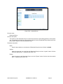
5.8.3
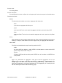
Simple Counter
The function of the Simple Counter is to collect information and provide counting about the
traffic of the port, whether the packet is good or bad.
In Figure 5.13, the screen shows all ports’ counter information at the same time. Each data field
is 20-digits. If the counting is overflow, the counter will be reset and restart counting. The data is
updated based on the time interval defined by the user. The valid range is three to ten seconds.
The refresh interval is used to set the update frequency. Default update time is three seconds.
Function name:
Simple Counter
Function description:
Displays the summary counting of each port’s traffic, including Tx Byte, Rx Byte, Tx Packet, Rx
Packet, Tx Collision and Rx Error Packet.
Parameters description:
Tx Byte:
Total transmitted bytes.
Rx Packet:
Waters Network Systems
2800M/MR User’s Manual
Page 43
The number of the packets received.
Tx Packet:
The number of the packets transmitted.
Tx Packet:
The number of the packets received.
Tx Collision:
Number of collisions.
Rx Error Packet:
Number of bad packets received.
Figure 5.14 – Simple Counter
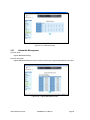
5.8.4
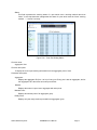
Detail Counter
The function of the Detail Counter is to collect information and provide the counting for the
traffic of the port, whether the packet is good or bad.
In Figure 5.14, the counter is displayed one port at a time. To see another port’s counter, pull
down the Select list. The figures for the port you have chosen will be displayed.
Waters Network Systems
2800M/MR User’s Manual
Page 44
Figure 5.15 – Detail Counter
Each data field is 20-digits. If the counting overflows, the counter will be reset and counting will
be restarted. The data is updated based on the time interval defined by the user. The valid
range is three to ten seconds. The refresh interval is used to set the update frequency. Default
update time is three seconds.
Function name:
Detail Counter
Function description:
Displays the detailed number of each port’s traffic. In Figure 5.14, the window shows all counter
information for one port at a time.
Parameter description:
Rx Packets:
The number of packets received.
Rx Octets:
Total received bytes.
Rx Errors:
Number of bad packets received.
Waters Network Systems
2800M/MR User’s Manual
Page 45
Rx Unicast Packets:
Displays the number of received unicast packets
Rx Broadcast Packets:
Displays the number of received broadcast packets.
Rx Multicast Packets:
Displays the number of received multicast packets.
Rx Pause Packets:
Displays the number of received pause packets.
Tx Collisions:
Number of collisions from transmitting frames.
Tx Single Collision:
Number of frames transmitted that experienced exactly one collision.
Tx Multiple Collision:
Number of frames transmitted that experienced more than one collision.
Tx Drop Packets:
Number of frames dropped due to excessive collisions, late collisions or frame aging.
Tx Deferred Transmit:
Number of frames delayed to transmission because the medium is busy.
Tx Late Collision:
Number of times that a collision is detected later than 512 bit-times into the transmission of a
frame.
Tx Excessive Collision:
Number of frames that are not transmitted because the frame has experienced 16 transmission
attempts.
Packets 64 Octets:
Number of 64-byte frames from good and bad packets received.
Packets 65-127 Octets:
Number of 65 ~ 127-byte frames from good and bad packets received.
Packets 128-255 Octets:
Number of 128 ~ 255-byte frames from good and bad packets received.
Packets 256-511 Octets:
Number of 256 ~ 511-byte frames from good and bad packets received.
Waters Network Systems
2800M/MR User’s Manual
Page 46
Packets 512-1023 Octets:
Number of 512 ~ 1023-byte frames from good and bad packets received.
Packets 1024- 1522 Octets:
Number of 1024-1522-byte frames from good and bad packets received.
Tx Packets:
The number of packets transmitted.
TX Octets:
Total transmitted bytes.
Tx Unicast Packets:
Displays the number of transmitted unicast packets.
Tx Broadcast Packets:
Displays the number of transmitted broadcast packets.
Tx Multicast Packets:
Displays the number of transmitted multicast packets.
Tx Pause Packets:
Displays the number of transmitted pause packets.
Rx FCS Errors:
Number of bad FSC packets received.
Rx Alignment Errors:
Number of Alignment error packets received.
Rx Fragments:
Number of short frames (< 64 bytes) with invalid CRC.
Rx Jabbers:
Number of long frames (according tomax_length register) with invalid CRC.
Rx Drop Packets:
Frames dropped due to the lack of receiving buffer.
Rx Undersize Packets:
Number of short frames (<64 Bytes) with valid CRC.
Rx Oversize Packets:
Number of long frames (according to max_length register) with valid CRC.
Waters Network Systems
2800M/MR User’s Manual
Page 47
5.9
SNMP Configuration
Any Network Management System (NMS) running the Simple Network Management Protocol
(SNMP) can manage devices equipped with the SNMP agent, provided that the Management
Information Base (MIB) is installed correctly on the managed devices. SNMP is a protocol that is
used to govern the transfer of information between SNMP manager and agent. This protocol
traverses the Object Identity (OID) of the management Information Base (MIB), described in the
form of SMI syntax.
SNMP is passive except for the issuing the trap information. The switch supports a function to
turn on or off the SNMP agent. If you set the field SNMP to Enable, the SNMP agent will be
launched. All supported MIB OIDs, including RMON MIB, can be accessed via SNMP manager.
If SNMP is set to Disable, the SNMP agent will not be activated. The related Community Name,
Trap Host IP Address, Trap and all MIB counters will be ignored.
Function name:
SNMP Configuration
Function description:
This function is used to configure SNMP settings, community name, trap host and public traps as
well as the throttle of SNMP. SNMP manager must pass the authentication by identifying both
community names. It can then can access the MIB information of the target device. So, both
parties must have the same community name. Once you have completed the setting, click Apply.
Parameters description:
SNMP:
The term SNMP here is used for the activation or de-activation of SNMP. Default is Enable.
Get/Set/Trap Community:
Community name is used as the password for authenticating if the requesting network
management unit belongs to the same community group. If they don’t have the same
community name, they don’t belong to the same group. Hence, the requesting network
management unit cannot access the device with a different community name via SNMP
protocol; If they both have the same community name, they can talk to each other.
The community name is user-definable with a maximum length of 15 characters and is case
sensitive. No blank spaces are permitted in the community name string. Any printable character
is allowable.
The community name for each function works independently. Each function has its own
community name. For example, the community name for GET only works for the GET function
and can’t be applied to other functions such as SET and Trap.
Default SNMP function: Enable
Default community name for GET: public
Default community name for SET: private
Default community name for Trap: public
Default Set function: Enable
Default trap host IP address: 0.0.0.0
Default port number: 162
Waters Network Systems
2800M/MR User’s Manual
Page 48
Trap:
There are six trap hosts supported. Each of them has its own community name and IP address
and is user-definable. To set up a trap host means to create a trap manager by assigning an IP
address to host the trap message. In other words, the trap host is a network management unit
with SNMP manager receiving the trap message from the managed switch with SNMP agent
issuing the trap message. Six trap hosts can prevent the important trap messages from being
lost.
For each public trap, the switch supports the trap events Cold Start, Warm Start, Link Down,
Link Up and Authentication Failure Trap. They can be enabled or disabled individually. When
enabled, the corresponding trap will actively send a trap message to the trap host when a trap
happens. If all public traps are disabled, no public trap message will be sent. As to the
Enterprise (no. 6) trap is classified as private trap, which are listed in the Trap Alarm
Configuration function folder.
Default for all public traps: Enable.
Figure 5.16 – SNMP Configuration
5.10
DHCP Boot
The DHCP Boot function is used to spread the request broadcast packet into a bigger time
frame. This is done to prevent the traffic congestion due to broadcast packets from many
network devices which may seek its NMS, boot server, DHCP server and many connections
predefined when the whole building or block loses power and then reboots and recovers.
Switches and other network devices on the LAN will try their best to find the server to obtain
services or try to set up the predefined links, so they will issue many broadcast packets in the
network.
The switch supports a random delay time for DHCP and boot delay for each device. This
suppresses the broadcast storm while all devices are at booting stage in the same time. The
maximum user-defined delay time is 30 sec. If DHCP Broadcasting Suppression function is
enabled, the delay time is set randomly, ranging from 0 to 30 seconds, because the exact delay
time is computed by the switch itself. The default is Disable.
Waters Network Systems
2800M/MR User’s Manual
Page 49
Figure 5.17 – DHCP Boot
5.11
IGMP Snooping
IGMP snooping is used to establish the multicast groups to forward multicast packets to
member ports. IGMP snooping avoids wasting the bandwidth while IP multicast packets are
running over the network. A switch that does not support IGMP snooping cannot tell a multicast
packet from broadcast packet, so it treats them as broadcast packets. Without IGMP snooping,
the multicast packet forwarding function is no different from broadcast packets.
A switch with IGMP snooping supports the functions of query, report and leave. A type of packet
exchanged between IP multicast router/switch and IP multicast host can update the information
of the multicast table when a member (port) joins or leaves an IP multicast destination address.
With this function, once a switch receives an IP multicast packet, it will forward the packet to the
members who had joined a specified IP multicast group.
Multicast packets will be discarded by IGMP Snooping if the user transmits multicast packets to
the multicast group which has not been set-up in advance.
Waters Network Systems
2800M/MR User’s Manual
Page 50
Figure 5.18 – IGMP Snooping Configuration
Function name:
IGMP Snooping Status
Function description:
IGMP is used to snoop the status of IP multicast groups and display its associated information in
both tagged VLAN and non-tagged VLAN networks. By enabling IGMP, you can monitor the IGMP
snooping information, which contains the multicast member list with the multicast groups, VID and
member port.
Parameter description:
IGMP snooping mode selection:
The switch supports three kinds of IGMP Snooping status:
Disable:
Use Disable mode to disable IGMP Snooping function.
Default: Disable
Active:
In Active mode, IGMP snooping will periodically issue the Membership Query message
to all hosts attached to it and gather the Membership report message to update the
database of the Multicast table. This reduces the unnecessary multicast traffic.
Passive:
In Passive mode, IGMP snooping will not periodically poll the hosts in the groups. The
switch will send a Membership Query message to all hosts only when it has received a
Membership Query message from a router.
IP Address:
Displays multicast group IP addresses that are registered on this device.
VLAN ID:
Waters Network Systems
2800M/MR User’s Manual
Page 51
Displays VLAN ID for each multicast group.
Member Port:
Displays member ports that join each multicast group.
Function name:
Allowed Group
Function description:
The Allowed Group function allows IGMP Snooping to set up the IP multicast table based on
user’s specific conditions. IGMP report packets that meet the items you set up will be joined or
form the multicast group.
Figure 5.19 – Allowed Group
Parameter description:
IP Range:
The switch supports two option types for managed valid IP range, including Any and
Custom. Default is Any. In case that Custom had been chosen, you can assign an
effective IP range. The valid range is 224.0.0.0~239.255.255.255.
VID:
The switch supports two option types for managed valid VLAN VID, including Any and
Custom. Default is Any. When you choose Custom, you can fill in VID number. The valid
VID range is 1~4094.
Port:
The switch supports two option types for managed valid port range, including Any and
Custom. Default is Any. You can select the ports to be used and restricted in the allowed
group configuration if Custom has been chosen.
Waters Network Systems
2800M/MR User’s Manual
Page 52
Add:
A new entry of allowed group configurations can be created after the parameters as
mentioned above had been setup by choosing Add.
Edit:
The entry also can be modified by choosing Edit.
Delete:
The entry of allowed group configuration can be removed from the allowed group.
5.12
VLANs
The switch supports Tag-based VLAN (802.1q) and Port-based VLANs. 256 active VLANs are
supported and VLAN ID can range from 1~4094. VLAN configuration is used to partition your
LAN into small segments based on your LAN requirements. By properly configuring VLANs,
you can improve security and increase performance.
5.12.1
VLAN Mode
Function name:
VLAN Mode Setting
Function description:
The VLAN Mode Selection function includes two modes: Port-based and Tag- based. Choose a
mode by using the drop-down list. Click Apply and the settings will take effect immediately.
Parameter description:
VLAN Mode:
Tag-based:
Tag-based VLAN identifies its member by VID. Tag-based VLANs are different from portbased VLANs. If there are additional rules in ingress filtering list or egress filtering list, the
packet will be screened with filtering criteria to determine if it can be forwarded. The switch
supports 802.1q.
Each tag-based VLAN must be assigned a VLAN name and VLAN ID. Valid VLAN ID is 14094. You may create total up to 256 Tag VLAN groups.
Port-based:
Port-based VLAN is defined by port. Any packet coming in or out from any one port of a
port-based VLAN will be accepted. No filtering criterion applies in port-based VLAN. The
only criterion is the physical port you connect to. For example, for a port-based VLAN
named PVLAN-1 contains port members Ports 1, 2, 3 & 4, and if you are connected to Port
1, you can communicate with Port 2-4. If you are connected to Port 5, you cannot
communicate with those ports. Each port-based VLAN must be assigned a group name.
This switch can support up to a maximum of 24 port-based VLAN groups.
Waters Network Systems
2800M/MR User’s Manual
Page 53
Symmetric VLAN:
Symmetric VLAN follows an Ingress Rule (Rule 1, The Ingress Filtering Rule 1 is “forward only
packets with VID matching this port’s configured VID”.). For example, if port 1 receives a
tagged packet with VID=100 (VLAN name=VLAN100), and if Symmetric-VLAN function is
enabled, the switch will check to see if port 1 is a member of VLAN100. If it is, the received
packet is forwarded; otherwise, the received packet is dropped.
Note: If Symmetric is enabled, and port 1, for example, receives an untagged packet, the
switch will apply the PVID of port 1 to tag this packet. The packet then will be forwarded. But if
the PVID of port 1 is not 100, the packet will be dropped.
SVL:
While SVL is enable, all VLANs use the same filtering database storing the membership
information of the VLAN to learn or look up the membership information of the VLAN. If SVL is
Disabled, it means learning mode is IVL. In this mode, different VLANs use a different filtering
database storing the membership information of the VLAN to learn or look up the information of
a VLAN member.
Double Tag:
Double-tag mode belongs to the tag-based mode; however, it would treat all frames as untagged ones,
which means that tag with PVID will be added into all packets. These packets will be forwarded as Tagbased VLAN. So, the incoming packets with tag will become the double-tag ones.
Figure 5.20 – VLAN Mode
5.12.2
Tag-based Group
Function name:
Tag-based Group Configuration
Waters Network Systems
2800M/MR User’s Manual
Page 54
Function description:
Displays the information of existing Tag-based VLAN Groups. You can also easily create, edit and
delete a Tag-based VLAN group by choosing the Add, Edit or Delete functions. Users can add a
new VLAN group by inputting a new VLAN name and VLAN ID after choosing Add.
Parameter description:
VLAN Name:
The name defined by administrator is associated with a VLAN group. Valid letters are A-Z, a-z,
0-9, “-“, and “_” characters. The maximal length is 15 characters.
VID:
VLAN identifier. Each tag-based VLAN group has a unique VID. It appears only in tag-based
and Double-tag modes.
Member:
This is used to enable or disable when a port is a member of the new added VLAN. Enable
means it is a member of the VLAN. Check the box beside the port x to enable it.
Figure 5.20 – Tag-based Group
5.21 – Tag-based Group
Waters Network Systems
2800M/MR User’s Manual
Page 55
Add Group:
Input the VLAN name, VID and then choose the member by clicking the check box beside the
port No. to create a new Tag-based VLAN. The parameter of Untag stands for an egress rule of
the port. If you check box beside the port No., outgoing packets with this VID from this port will
be untagged. Choose Apply save the setting.
Figure 5.22 – Tag-based VLAN
Delete Group:
Choose Delete to remove the selected group entry from the Tag-based group table.
Figure 5.23 – Tag-based Group
Edit a group:
Waters Network Systems
2800M/MR User’s Manual
Page 56
Select a group entry and choose Edit to modify a group’s description, member and untag
settings.
5.12.3
PVID
Function name:
PVID
Function description:
In PVID Setting, user can input VID number to each port. The range of VID number is from 1 to 4094.
You can also can choose ingress filtering rule (Rule 2) to each port. The Ingress Filtering Rule 2 is
“drop untagged frames”. While Rule 2 is enabled, the port will discard all Untagged-frames.
Figure 5.24 - PVID
Parameter description:
Port 1-26:
Port number.
PVID:
The PVID range will be 1-4094. Before you set a number x as PVID, you have to create a Tagbased VLAN with VID x. For example, if port x receives an untagged packet, the switch will
apply the PVID (assume as VID y) of port x to tag this packet. The packet then will be
forwarded as the tagged packet with VID y.
Default Priority:
Default priority is based on 802.1p QoS and affects untagged packets. When packets enter the
switch, the priority precedence according to the Default Priority setting and map to 802.1p
priority setting in the QoS function is followed. For example, while you set Default Priority of port
2 with 2 and transmit untagged packets to port 2, these packets will follow priority 2 precedence
and will be placed into Queue 1.
Waters Network Systems
2800M/MR User’s Manual
Page 57
Drop Untag:
Drop untagged frame. You can configure a given port to accept all frames (Tagged and
Untagged) or just receive tagged frames. If the former is the case, then the packets with tagged
or untagged will be processed. If the later is the case, only the packets carrying VLAN tag will
be processed and the rest packets will be discarded.
5.12.4
Port-based Group
Function name:
Port-based Group Configuration
Function description:
Displays the information of the existing Port-based VLAN Groups. You can easily create, edit and
delete a Port-based VLAN group by choosing Add, Edit and Delete. You can add a new VLAN
group by inputting a new VLAN name.
Parameter description:
VLAN Name:
The name defined by administrator is associated with a VLAN group. Valid letters are A-Z, a-z,
0-9, “-“, and “_” characters. The maximum length is 15 characters.
Member:
Used to enable or disable if a port is a member of the new added VLAN, Enable means it is a
member of the VLAN. Click the check box beside the port x to enable it.
Figure 5.25 – Port-based Group
Waters Network Systems
2800M/MR User’s Manual
Page 58
Add Group:
Create a new Port-based VLAN. Input the VLAN name and choose the member by clicking the
check box beside the port No. Choose Apply save the setting.
Figure 5.26 – Port-based VLAN
Delete Group:
Choose Delete to remove the selected group entry from the Port-based group table.
Figure 5.27 – Port-based Group
Edit a group:
Select a group entry and press Edit to modify a group‘s description and member set.
Waters Network Systems
2800M/MR User’s Manual
Page 59
Select a group entry and select Edit. This allows you to modify the group’s setting.
5.13
MAC Table
MAC Table Configuration includes the following functions:
MAC Table Information
MAC Table Maintenance
Static Forward
Static Filter
MAC Alias
Function name:
MAC Table Information
Function Description:
Displays the static or dynamic learning MAC entry and the state for the selected port.
Parameter description:
Port:
Select the desired port.
Search:
Click on search to find your entry
MAC:
Displays the MAC address of the entry selected from the searched MAC entries table.
Alias:
Set up the Alias for the selected MAC entry.
Set Alias:
Set the Alias of MAC entry.
Search:
Find the entry.
Previous Page:
Move to the previous page.
Next Page:
Move to the next page.
Alias:
The Alias of the searched entry.
MAC Address:
Waters Network Systems
2800M/MR User’s Manual
Page 60
The MAC address of the searched entry.
Port:
The port that exists in the searched MAC Entry.
VID:
VLAN Group that MAC Entry exists.
State:
Display the method that this MAC Entry is built. It may show Dynamic MAC or Static MAC.
Figure 5.28 – MAC Table Information
Function Name:
MAC Table Maintenance
Function Description:
This function allows the user to set up the processing mechanism of MAC Table. An idle MAC
address exceeding MAC Address Age-out Time will be removed from the MAC Table. The range of
Age-out Time is 10-1000000 seconds, and the setup of this time will have no effect on static MAC
addresses.
In addition, the learning limit of MAC maintenance is able to limit the amount of MAC that each port
can learn.
Parameter description:
Aging Time:
Delete a MAC address idling for a period of time from the MAC Table, which will not affect static
MAC address. Range of MAC Address Aging Time is 10-1000000 seconds. The default Aging
Time is 300 seconds.
Learning Limit:
Used to set the maximum amount of MAC that each port can learn. Valid value of learning limit
for port 1~24 ranges from 0-8191. As to port 25~port 26, only the fixed value “8192” is assigned
Waters Network Systems
2800M/MR User’s Manual
Page 61
to these two ports. This value cannot be configured.
Figure 5.29 – MAC Maintenance
Function Name:
Static Setting
Function Description:
The function of Static is used to configure MAC’s manners inside of the switch. Three kinds of
manners are included in this function: static, static with destination drop and static with source drop.
When static is chosen, assign a MAC address to a specific port. All of the switch’s traffics sent to
this MAC address will be forwarded to this port.
When static with destination drop is chosen, the packet will be dropped if its DA is equal to the
value you set. This setting belongs to the global setting, so, it may affect all ports’ transmission of the
packets.
As static with source drop is chosen, the packet will be dropped if its SA is equal to the value you
set. This setting belongs to the global one, so, it may affect all ports’ transmission of the packets.
Waters Network Systems
2800M/MR User’s Manual
Page 62
Figure 5.30 – Static MAC
Parameter description:
MAC:
MAC is six-byte long Ethernet hardware address and usually expressed by hex and separated
by hyphens. For example, 00 – 19 – B6 – C5 – 00 – 01
VID:
VLAN identifier. This will be filled only when tagged VLAN is applied. Valid range is 1 ~ 4094.
Queue:
Set up the priority (0~3) for the MAC.
Forwarding Rule:
Static:
A MAC address is assigned to a specific port. All of the switch’s traffics sent to this MAC
address will be forwarded to this port.
Static with Destination Drop:
While the DA of the incoming packets meets the value you set, these packets will be
dropped.
Static with Source Drop:
While the SA of the incoming packets meets the value you set, these packets will be
dropped.
Port:
Select the port number you would like to setup in the switch.
Waters Network Systems
2800M/MR User’s Manual
Page 63
Function name:
MAC Alias
Function description:
MAC Alias function is used to let you assign a MAC address a plain English name. This will help you
tell which MAC address belongs to which user in the illegal access report. At the initial time, it shows
all pairs of the existed alias name and MAC address.
There are three MAC alias functions in this function folder, including MAC Alias Add, MAC Alias Edit
and MAC Alias Delete. You can choose Create/Edit to add/modify a new or an existed alias name
for a specified MAC address, or mark an existed entry to delete it. An alias name must be composed
of A-Z, a-z and 0-9 only and has a maximum length of 15 characters.
Function name:
MAC Alias Create/Edit or Delete
Function description:
In the MAC Alias function, MAC Alias Add/Edit function is used to let you add or modify an
association between MAC address and a plain English name. You can choose Create/Edit to add a
new record with name.
As to MAC Alias Delete function is used to let you remove an alias name to a MAC address. You can
select an existed MAC address or alias name to remove.
Figure 5.31 – MAC Alias
Waters Network Systems
2800M/MR User’s Manual
Page 64
Parameter description:
MAC Address:
MAC address is a six-byte long Ethernet hardware address and usually expressed by hex and
separated by hyphens. For example, 00 – 19 – B6 – C5 – 00 – 02
Alias:
MAC alias name you assign.
Note: If there are too many MAC addresses learned in the table, we recommend you input the
MAC address and alias name directly.
5.14
GVRP Configuration
GVRP is an application based on the Generic Attribute Registration Protocol (GARP), mainly
used to automatically and dynamically maintain the group membership information of the
VLANs. GVRP provides the VLAN registration service through a GARP application. The GARP
Information Declaration (GID) is used to maintain the ports associated with their attribute
database and GARP Information Propagation (GIP) to communicate among switches and end
stations. With GID information and GIP, GVRP state machine maintain the contents of Dynamic
VLAN Registration Entries for each VLAN and propagate these information to other GVRPaware devices to setup and update their knowledge database, the set of VLANs associated with
currently active members, and through which ports these members can be reached.
Figure 5.32 – GVRP Configuration
The following three functions are supported with GVRP:
Function name:
GVRP Config
Function description:
Waters Network Systems
2800M/MR User’s Manual
Page 65
The function of GVRP Config is used to configure each port’s GVRP operation mode. There are
seven parameters to be configured which are described below.
Parameter description:
GVRP State Setting:
This function allows you to enable or disable the GVRP function. Use the drop down list and
select the Downward arrow key to choose Enable or Disable. Select Apply and the function
will take effect immediately.
Join Time:
Used to declare the Join Time in unit of centisecond. Valid time range: 20 –100 centisecond,
Default: 20 centisecond.
Leave Time:
Used to declare the Leave Time in unit of centisecond. Valid time range: 60 –300 centisecond,
Default: 60 centisecond.
Leave All Time:
A registered device will be de-registered at the end of this time period. If someone still issues a
new join, then a registration will be kept in the switch. Valid range: 1000-5000 unit time, Default:
1000 unit time.
Default Applicant Mode:
There are two modes that indicate the type of participant:
participant.
normal participant and non-
Normal:
In the normal participant mode, the switch participates normally in GARP protocol
exchanges. The default setting is Normal.
Non-Participant:
In the non-participant mode, the switch does not send or reply any GARP messages.
The switch listens for messages and reacts for the received GVRP BPDU.
Default Registrar Mode:
There are three types of parameters for registrar mode: registrar administrative control value,
normal registrar, fixed registrar and forbidden registrar.
Normal:
The Registrar responds normally to incoming GARP messages. The default setting is
Normal.
Fixed:
The Registrar ignores all GARP messages, and all members remain in the registered
(IN) state.
Forbidden:
The Registrar ignores all GARP messages, and all members remain in the
unregistered (EMPTY) state.
Restricted Mode:
This function is used to restrict dynamic VLAN be created when this port received GVRP PDU.
There are two modes: disable and enable.
Waters Network Systems
2800M/MR User’s Manual
Page 66
Disabled:
In this mode, the switch dynamic VLAN will be created when this port received GVRP
PDU. The default setting is Normal.
Enabled:
In this mode, the switch does not create dynamic VLAN when this port received
GVRP PDU. Except received dynamic VLAN message of the GVRP PDU is an
existed static VLAN in the switch. This port will be added into the static VLAN
members dynamically.
Function name:
GVRP Counter
Function description:
GVRP counters are divided into Received and Transmitted categories which allows you monitor the
GVRP actions. They are GARP packets.
Figure 5.33– GVRP Counter
Parameter description:
Received:
Total GVRP Packets:
Total GVRP BPDU received by the GVRP application.
Invalid GVRP Packets:
Number of invalid GARP BPDU received by the GARP application.
LeaveAll Message Packets:
Number of GARP BPDU with Leave All message received by the GARP application.
JoinEmpty Message Packets:
Number of GARP BPDU with Join Empty message received by the GARP application.
Waters Network Systems
2800M/MR User’s Manual
Page 67
JoinIn Message Packets:
Number of GARP BPDU with Join In message received by the GARP application.
LeaveEmpty Message Packets:
Number of GARP BPDU with Leave Empty message received by the GARP application.
Empty Message Packets:
Number of GARP BPDU with Empty message received by the GARP application.
Transmitted:
Total GVRP Packets:
Total GARP BPDU transmitted by the GVRP application.
Invalid GVRP Packets:
Number of invalid GARP BPDU transmitted by the GVRP application.
LeaveAll Message Packets:
Number of GARP BPDU with Leave All message transmitted by the GARP application.
JoinEmpty Message Packets:
Number of GARP BPDU with Join Empty message transmitted by the GARP application.
JoinIn Message Packets:
Number of GARP BPDU with Join In message transmitted by the GARP application.
LeaveEmpty Message Packets:
Number of GARP BPDU with Leave Empty message transmitted by the GARP application.
Empty Message Packets:
Number of GARP BPDU with Empty message transmitted by the GARP application.
Function name:
GVRP Group Information
Function description:
To show the dynamic group member and their information.
Parameter description:
Current Dynamic Group Number :
The number of GVRP groups that are currently created.
VID:
VLAN identifier. When a GVRP group is created, each dynamic VLAN group owns its VID. Valid
range is 1 ~ 4094.
Member Port:
Those are the members belonging to the same dynamic VLAN group.
Edit Administrative Control:
When you create a GVRP group, use the Administrative Control function to change the
Applicant Mode and Registrar Mode of a GVRP group member.
Waters Network Systems
2800M/MR User’s Manual
Page 68
Refresh:
Refresh function allows you to see current GVRP group status.
Figure 5.34– GVRP Group Information
5.15
Spanning Tree Configuration (STP) Configuration
The Spanning Tree Protocol (STP) is a standardized method (IEEE 802.1D) used to avoid loops
in switched networks. When STP is enabled, only one path is active between any two nodes on
the network at a time. Once Spanning Tree Protocol has been enabled, advanced functions can
be configured. It is recommend that STP is enabled to ensure a single active path on the
network.
5.15.1
STP Status
Function name:
STP Status
Function description:
Spanning Tree Status displays the current status of 12 parameters. The 12 parameters are described
below:
Parameter description:
STP State:
Displays the current STP Enabled / Disabled status. Default is Disabled.
Bridge ID:
Displays the switch’s bridge ID which is the MAC address of this switch.
Bridge Priority:
Displays the switch’s current bridge priority setting. Default is 32768.
Waters Network Systems
2800M/MR User’s Manual
Page 69
Designated Root:
Displays the root bridge ID of this network segment. If this switch is a root bridge, the
Designated Root will show this switch’s bridge ID.
Designated Priority:
Displays the current root bridge priority.
Root Port:
Displays port number connected to root bridge with the lowest path cost.
Root Path Cost:
Displays the path cost between the root port and the designated port of the root bridge.
Current Max. Age:
Displays the current root bridge maximum age time. Maximum age time is used to monitor STP
topology. When a bridge does not receive a hello message from root bridge until the maximum
age time is counted down to 0, the bridge will treat the root bridge as malfunctioned and issue a
Topology Change Notification (TCN) BPDU to all other bridges.
All bridges in the LAN will re-learn and determine the root bridge. Maximum Age time is
assigned by root bridge in unit of seconds. Default is 20 seconds.
Current Forward Delay:
Displays the current root bridge forward delay time. The value of Forward Delay time is set by
root. The Forward Delay time is defined as the time spent from Listening state moved to
Learning state or from Learning state moved to Forwarding state of a port in bridge.
Hello Time:
Displays the current hello time of the root bridge. Hello time is a time interval specified by root
bridge. It is used to request all other bridges periodically sending hello message to the bridge
attached to its designated port.
STP Topology Change Count:
STP Topology Change Count expresses the time spent in a unit of seconds since the beginning
of the Spanning Tree Topology Change to the end of the STP convergence. Once the STP
change is converged, the Topology Change count will be reset to 0. The figures showing in the
screen may not be the exact time it spent but very close to, because the time is eclipsing.
Time Since Last Topology Change:
Time Since Last Topology Change is the accumulated time in unit of seconds the STP has been
since the last STP Topology Change was made. When Topology Change is initiated again, the
counter will be reset to 0 and resume counting once the STP topology change is completed.
Waters Network Systems
2800M/MR User’s Manual
Page 70
Figure 5.35 – STP Status
5.15.2
Configuration
STP includes Rapid Spanning Tree Protocol (RSTP). STP has six parameters to be configured.
These parameters are described below.
Function name:
STP Configuration
Function description:
Set the following Spanning Tree parameters to control STP function (enable/disable). Select mode
RSTP/STP and affect STP state machine behavior to send BPDU in the switch. The default setting
of STP is Disable.
Parameter description:
Spanning Tree Protocol:
Set 802.1W Rapid STP function Enable / Disable. Default is Disable.
Bridge Priority:
The lower the number for bridge priority, the higher the priority it will have. Usually, the bridge
with the highest bridge priority is the root. If you want this switch to be the root bridge, set the
value lower than that of the bridge in the LAN. The valid value is 0 ~ 61440. The default is
32768.
Hello Time:
Hello Time is used to determine the periodic time to send normal BPDU from designated ports
among bridges. It decides how long a bridge should notify other bridges to say that it is up and
connected. If the GSM switch is the root bridge of the LAN, for example, all other bridges will
use the hello time assigned by this switch to communicate with each other. The valid value is 1
~ 10 in unit of seconds.
Default is 2 seconds.
Max. Age:
Waters Network Systems
2800M/MR User’s Manual
Page 71
When the GSM switch is the root bridge, the whole LAN will apply the number set by the switch
as their maximum age time. When a bridge received a BPDU originating from the root bridge
and if the message age conveyed in the BPDU exceeds the Max. Age of the root bridge, the
bridge will treat the root bridge as malfunctioning and issue a Topology Change Notification
(TCN) BPDU to all other bridges. All bridges in the LAN will re-calculate to determine who the
root bridge is. The valid value of Max. Age is 6 ~ 40 seconds. Default is 20 seconds.
Forward Delay:
You can set the root bridge forward delay time. This figure is set by the root bridge only. The
forward delay time is defined as the time spent from Listening state moved to Learning state
and also from Learning state moved to Forwarding state of a port in bridge. The forward delay
time contains two states, Listening state to Learning state and Learning state to Forwarding
state. It assumes that forward delay time is 15 seconds, then total forward delay time will be 30
seconds.
The valid value is 4 ~ 30 seconds, default is 15 seconds.
Force Version:
Two options are offered for the STP algorithm. One is RSTP and the other is STP. If STP is
chosen, RSTP will run as a legacy STP. The switch supports RSTP (802.1w) which is backward
compatible with STP (802.1d).
Figure 5.36 – STP Status
Waters Network Systems
2800M/MR User’s Manual
Page 72
5.15.3
STP Port Configuration
Function name:
STP Port Setting
Function description:
In the STP Port Setting, one item selection and five parameters are available for setup. You can
disable and enable each port. You can set Path Cost and Priority for each port and set Admin
Edge Port and Admin Point To Point.
Parameter description:
Port Status:
Displays the current state of a port for viewing only. According to the 802.1w specification,
there are three possible states.
DISCARDING state indicates that this port can neither forward packets nor contribute
learning knowledge.
LEARNING state indicates this port can now contribute its learning knowledge but cannot
forward packets.
FORWARDING state indicates this port can both contribute its learning knowledge and
forward packets normally.
Note: Three other states (Disable state, BLOCKING state and LISTENING state) defined in the
802.1d specification are now represented as DISCARDING state.
Path Cost Status:
The contribution value of the path through this port to Root Bridge. STP algorithm determines a
best path to Root Bridge by calculating the sum of path cost contributed by all ports on this path.
A port with a smaller path cost value would become the Root Port.
Configured Path Cost:
The range is 0 – 200,000,000. If the path cost is set to zero, the STP will get the recommended
value resulted from auto-negotiation of the link accordingly and display this value in the field of
Path Cost Status. Otherwise, the value set by the administrator set up will be displayed.
802.1w RSTP recommended value: (Valid range: 1 – 200,000,000)
10 Mbps:
2,000,000
100 Mbps:
200,000
1 Gbps:
20,000
Default:
0
Priority:
Port Priority and Port Number are combined to form the Port ID. Port IDs are often compared in
order to determine which port of a bridge would become the Root Port. The range is 0 – 240.
Waters Network Systems
2800M/MR User’s Manual
Page 73
Default is 128.
Admin Edge Port:
If you select Yes, this port will be an edge port. An Edge Port is a port connected to a device
that knows nothing about STP or RSTP. Usually, the connected device is an end station. Edge
Ports will immediately transit to forwarding state and skip the listening and learning state
because the edge ports cannot create bridging loops in the network. This will expedite the
convergence. When the link on the edge port toggles, the STP topology keeps unchanged.
Unlike the designate port or root port though, an edge port will transit to a normal spanning-tree
port immediately if it receives a BPDU.
Default: No
Admin Point To Point:
A port is a point-to-point link, from RSTP’s view, if it is in full-duplex mode. It is a shared link if it
is in half-duplex mode. RSTP fast convergence can only happen on point-to-point links and on
edge ports. This can expedite the convergence because this will have the port fast transited to
forwarding state.
There are three parameters, Auto, True and False, used to configure the type of the point-topoint link. If the parameter is configured to Auto, RSTP will use the duplex mode resulting from
the auto-negotiation. If it goes into half-duplex, the port will not transit to Forwarding state. If it
is set as True, the port is treated as point-to-point link by RSTP and unconditionally transited to
Forwarding state. If it is set to False, fast transition to Forwarding state will not occur on this port.
Default: Auto
M Check:
Migration Check. Forces the port sending out an RSTP BPDU instead of a legacy STP BPDU at
the next transmission. The only benefit of this operation is to make the port quickly get back to
act as an RSTP port. Select M Check to send a RSTP BPDU from the port you specified.
Figure 5.37 – STP Port Configuration
Waters Network Systems
2800M/MR User’s Manual
Page 74
5.16
Trunking Configuration
The Port Trunking Configuration is used to configure the settings of Link Aggregation. More than
one port can be bundled with the same speed, full duplex and the same MAC to be a single
logical port. The logical port aggregates the bandwidth of these ports. This means you can
apply your current Ethernet equipment to build the bandwidth aggregation. For example, if
there are three Fast Ethernet ports aggregated in a logical port, then this logical port has
bandwidth three times as high as a single Fast Ethernet port.
The switch supports two types of port trunking methods:
LACP:
Ports using Link Aggregation Control Protocol (according to IEEE 802.3ad specification) as their
trunking method can choose their unique LACP GroupID (1~8) to form a logic trunked port.
The benefit of using LACP is that a port makes an agreement with its peer port before it
becomes a ready member of a trunk group (also called aggregator). LACP is safer than the
other trunking method - static trunk.
The switch LACP does not support the following:
Link Aggregation across switches
Aggregation with non-IEEE 802.3 MAC link
Operating in half-duplex mode
Aggregate the ports with different data rates
Static Trunk:
Ports using Static Trunk as their trunk method can choose their unique Static Group ID (also
1~3, this Static group ID can be the same with another LACP group ID) to form a logic trunked
port. The benefit of the using Static Trunk method is that a port can immediately become a
member of a trunk group without handshaking with its peer port. This is a disadvantage
because the peer ports of the static trunk group may not know that they should aggregate
together to form a logical trunked port. Using Static Trunk on both ends of a link is strongly
recommended. Low speed links will stay in not ready state when using static trunk to
aggregate with high speed links.
The switch supports a maximum of three trunk groups for LACP and additional three trunk
groups for Static Trunk. In the system capability view, only three “real trunked” groups are
supported. An LACP trunk group with more than one ready member-ports is a “real trunked”
group. An LACP trunk group with only one or less than one ready member-ports is not a “real
trunked” group. Any Static trunk group is a “real trunked” group.
Per Trunking Group supports a maximum of four ready member-ports. Please note that some
decisions will automatically be made by the system while you are configuring your trunking ports.
Some configuration examples are listed below:
Rule 1 – Maximum of three groups are allowed.
Rule 2 - The members of each group cannot exceed more than four ports.
Rule 3 – Group 1 and 2 cannot have as members ports 25 and 26.
Rule 4 – Group 3 cannot have members from 1 to 24 ports.
Waters Network Systems
2800M/MR User’s Manual
Page 75
Function name:
Port Setting/Status
Function description:
Port setting/status is used to configure the trunk property of each and every port in the switch system.
Parameter description:
Method:
This determines the method a port uses to aggregate with other ports.
None:
A port does not aggregate with other ports.
LACP:
A port uses LACP as its trunk method to aggregate with other ports also using LACP.
Static:
A port uses Static Trunk as its trunk method to aggregate with other ports also using Static
Trunk.
Group:
Ports choosing the same trunking method other than “None” must be assigned a unique Group
number (i.e. Group ID, valid value is from one to eight) so they can aggregate with each other.
Active LACP:
This field is only available when a port’s trunking method is LACP.
Active:
An Active LACP port begins to send LACPDU to its link partner as soon as the LACP
protocol entity takes control of this port.
Passive:
A Passive LACP port will not actively send LACPDU out until it receives an LACPDU from
its link partner.
Aggtr:
Aggtr is an abbreviation of “aggregator”. Every port is also an aggregator, and its own
aggregator ID is the same as its own port number. An aggregator is a representative of a
trunking group. Ports with same Group ID and using same trunking method will have the
opportunity to aggregate to a particular aggregator port. This aggregator port is usually the port
with the smallest port number within the trunking group.
Waters Network Systems
2800M/MR User’s Manual
Page 76
Status:
This field represents the trunking status of a port which uses a trunking method other than
“None”. It also represents the management link status of a port which uses the “None” trunking
method. “---“ means “not ready”
Figure 5.38 – Trunk Port Setting Status
Function name:
Aggregator View
Function description:
To display the current port trunking information from the aggregator point of view.
Parameter description:
Aggregator:
Displays the aggregator ID (from 1 to 26) of every port. Every port is also an aggregator, and its
own aggregator ID is the same as its own port number.
Method:
Displays the method a port uses to aggregate with other ports.
Member Ports:
Displays all member ports of an aggregator (port).
Ready Ports:
Displays only the ready member ports within an aggregator (port).
Waters Network Systems
2800M/MR User’s Manual
Page 77
Figure 5.39 – Aggregator View
Function name:
LACP Detail (LACP Aggregator Detailed Information)
Function description:
Displays the detailed information of the LACP trunking group.
Parameter description:
Actor:
The switch you are using to view LACP.
Partner:
The peer system from the aggregator’s view.
System Priority:
Displays the System Priority of a system ID.
MAC Address:
Displays the MAC Address of a system ID.
Port:
Displays the port number of an LACP port ID.
Key:
Displays the key value of the aggregator. The key value is determined by the LACP protocol
entity and can’t be set through management.
Trunk Status:
Displays the trunk status of a single member port.”---“ means “not ready”
Waters Network Systems
2800M/MR User’s Manual
Page 78
Figure 5.40 – LACP System Priority
Function name:
LACP System Priority
Function description:
Used to set the priority of the LACP system ID. LACP will only aggregate together the ports whose
peer link partners are all on a single system. Each system supports LACP will be assigned a globally
unique System Identifier for this purpose. A system ID is a 64-bit field comprising a 48-bit MAC
Address and 16-bit priority value.
Parameter description:
System Priority:
The System Priority can be set by the user. Its range is from 1 to 65535. Default: 32768
Hash Method:
DA+ SA, DA and SA are three Hash methods available for the Link Aggregation of the switch.
Packets will determine the path to transmit according to the mode of Hash chosen
Default: DA and SA
5.17
802.1x Configuration
802.1X port-based network access control provides a method to restrict users to access
network resources via authenticating user’s information. This restricts users from gaining access
to the network resources through a 802.1X-enabled port without authentication. To access the
network through a port under 802.1X control, you must first input your account name for
authentication and wait to gain authorization before sending or receiving any packets from a
802.1X-enabled port.
Waters Network Systems
2800M/MR User’s Manual
Page 79
Before the devices or workstations can access the network resources through the ports under
802.1X control, the devices or workstations must send an authentication request to the
authenticator. The authenticator passes the request to the authentication server to authenticate
and verify, and the server informs the authenticator to grant the request for authorization for the
ports.
According to IEEE 802.1X, there are three components are implemented:
Supplicant
Authenticator
Authentication server shown in Figure 5.41.
Supplicant:
An entity authenticated by an authenticator. Used to communicate with the Authenticator PAE
(Port Access Entity) by exchanging the authentication message when the Authenticator PAE
performs a request.
Authenticator:
An entity facilitates the authentication of the supplicant entity. It controls the state of the port,
authorized or unauthorized, according to the result of authentication message exchanged
between it and a supplicant PAE. The authenticator may request the supplicant to reauthenticate itself at a configured time period. Once re-authenticating has begun, the
controlled port remains in the authorized state until re-authentication fails.
A port acting as an authenticator is thought to be two logical ports, a controlled port and an
uncontrolled port. A controlled port can only pass packets when the authenticator PAE is
authorized. Otherwise, an uncontrolled port will unconditionally pass the packets with PAE
group MAC address, which has the value of 01-80-c2-00-00-03 and will not be forwarded by
MAC bridge, at any time.
Authentication server:
A device provides authentication service, through EAP, to an authenticator by using
authentication credentials supplied by the supplicant to determine if the supplicant is
authorized to access the network resource.
The overview of operation flow for the Figure 5.41 is quite simple. When Supplicant PAE
issues a request to Authenticator PAE, Authenticator and Supplicant exchanges
authentication message. Then, Authenticator passes the request to RADIUS server to verify.
Finally, RADIUS server replies if the request is granted or denied.
During the authentication process, the message packets, encapsulated by Extensible
Authentication Protocol over LAN (EAPOL), are exchanged between an authenticator PAE
and a supplicant PAE. The Authenticator exchanges the message to authentication server
using EAP encapsulation. Before successfully authenticating, the supplicant can only touch
the authenticator to perform authentication message exchange or access the network from
the uncontrolled port.
Waters Network Systems
2800M/MR User’s Manual
Page 80
Authentication
Server’s System
Authenticator’s System
Supplicant’s
System
Services Offered
by Authenticator
(e.g Bridge Relay)
Supplicant
PAE
Controlled port
Authenticator
PAE
Authentication
Server
Uncontrolled port
Port Authorize
MAC Enable
LAN
Figure 5.41
Figure 5.42 represents a typical configuration; a single supplicant, an authenticator and an
authentication server. B and C are in the internal network, D is the Authentication server running
RADIUS, switch at the central location which acts as Authenticator connecting to PC A. A is a
PC outside the controlled port, running Supplicant PAE. In this case, PC A wants to access the
services on device B and C. It first must exchange the authentication message with the
authenticator on the port it connected via EAPOL packet. The authenticator transfers the
supplicant’s credentials to Authentication server for verification. If successful, the authentication
server will notify the authenticator. PC A is then allowed to access B and C via the switch. If
there are two switches directly connected together instead of a single one, the link ports
connecting the two switches may have to perform two port roles: authenticator and supplicant,
because the traffic is bi-directional.
Authentication server
C
Authenticator
B
Supplicant A
Figure 5.42
Figure 5.43 illustrates the procedure of 802.1X authentication. There are steps for the login
based on 802.1X port access control management. The protocol used in the right side is EAPOL
and the left side is EAP.
1. At the initial stage, supplicant A is unauthenticated so the port acting as an authenticator is
in unauthorized state. Access is blocked in this stage.
Waters Network Systems
2800M/MR User’s Manual
Page 81
2. Either authenticator or supplicant can initiate the message exchange. If supplicant initiates
the process, it sends EAPOL-start packet to the authenticator PAE and authenticator will
immediately respond EAP-Request/Identity packet.
3. The authenticator periodically sends EAP-Request/Identity to the supplicant to request the
identity it wants to be authenticated.
4. If the authenticator doesn’t send EAP-Request/Identity, the supplicant will initiate EAPOLbeginning the process by sending it to the authenticator.
5. The Supplicant replies an EAP-Response/Identity to the authenticator. The authenticator will
embed the user ID into Radius-Access-Request command and send it to the authentication
server for identity confirmation.
6. After receiving the Radius-Access-Request, the authentication server sends Radius-AccessChallenge to the supplicant asking for inputting user password via the authenticator PAE.
7. The supplicant will convert the user password into the credential information, perhaps, in
MD5 format and replies an EAP-Response with this credential information as well as the
specified authentication algorithm (MD5 or OTP) to Authentication server via the
authenticator PAE. As per the value of the type field in message PDU, the authentication
server knows which algorithm should be applied to authenticate the credential information,
EAP-MD5 (Message Digest 5) or EAP-OTP (One Time Password) or other algorithm.
8. If user ID and password is correct, the authentication server will send a Radius-AccessAccept to the authenticator. If not correct, the authentication server will send a RadiusAccess-Reject.
9. When the authenticator PAE receives a Radius-Access-Accept, it will send an EAP-Success
to the supplicant. At this time, the supplicant is authorized and the port is connected to the
supplicant and is under 802.1X control in the authorized state. The supplicant and other
devices connected to this port can access the network. If the authenticator receives a
Radius-Access-Reject, it will send an EAP-Failure to the supplicant. This means the
supplicant has failed to authenticate. The port connected is in the unauthorized state, the
supplicant and the devices connected to this port won’t be allowed to access the network.
10. When the supplicant issues an EAP-Logoff message to Authentication server, the active port
being used is set to unauthorized.
Waters Network Systems
2800M/MR User’s Manual
Page 82
Bridge
LAN
PC
Radius Server
Port connect
Access blocked
EAPOL-Start
EAPOL
EAP
Radius
Authenticator
EAP-Request/Identity
Radius-Access-Request
EAP-Response/Identity
Radius-Access-Challenge
EAP-Request
Radius-Access-Request
EAP-Response (cred)
Radius-Access-Accept
EAP-Success
EAP-Failure
EAP-Logoff
Access allowed
Figure 5.43 – 802.1x Authentication
The type of authentication supported in the switch is multihost 802.1x. In this mode, once a
supplicant is authorized, the devices connected to this port can access the network resources.
802.1X Port-based Network Access Control function supported by the switch is complex.
Support, by basic multihost mode, can distinguish the device’s MAC address and its VID. The
following table summarizes the combination of the authentication status and the port status
versus the status of port mode, set in 802.1X Port mode, port control state, set in 802.1X port
setting. Entry Authorized means MAC entry is authorized.
Port Mode
Disable
Multihost
Multihost
Multihost
Multihost
Port Control
Don’t Care
Auto
Auto
ForceUnauthorized
ForceAuthorized
Authentication
Port Status
Don’t Care
Port Uncontrolled
Successful
Port Authorized
Failure
Port Unauthorized
Don’t Care
Port Unauthorized
Don’t Care
Port Authorized
Table 5.2
Waters Network Systems
2800M/MR User’s Manual
Page 83
Function name:
802.1X State Setting
Function description:
This function is used to configure the global parameters for RADIUS authentication in 802.1X port
security application.
Parameter description:
Radius Server:
RADIUS server IP address for authentication. Default: 192.168.1.1
Port number:
The port number to communicate with RADIUS server for the authentication service. The valid
value ranges 1-65535. Default port number is 1812.
Secret Key:
The secret key between authentication server and authenticator. It is a string with the length 1 –
31 characters. The character string may contain upper case, lower case and 0-9 without spaces.
Default: Radius
Figure 5.44 – 802.1X State Setting
Function name:
802.1X Mode Setting
Function description:
Set the operation mode of 802.1X for each port. In this device, multihost operation mode is
supported.
Parameter description:
Port Number:
Waters Network Systems
2800M/MR User’s Manual
Page 84
Indicate which port is selected to configure the 802.1X operation mode.
Mode:
802.1X operation mode. There are three options, including Disable, Normal and Advanced.
Default is Disable.
Disable
The chosen port acts as a plain port, which means 802.1X port access control does not
work on the port.
802.1X with multihost
In multihost mode, the devices connected to this port can access the network, once a
supplicant is authorized.
Figure 5.45 – 802.1X Port Configuration
Function name:
Port Security Management
Function description:
Displays each port status. In multihost mode, the port number and its status, authorized or
unauthorized are displayed.
Parameter description:
Port Number:
The port number to be chosen to show its 802.1X Port Status. The valid number is Port 1 – 26
Disable Mode:
Disable mode means the port is in the uncontrolled port sate, so the 802.1x authenticator is not
applied. Any node attached to this port can access the network without the 802.1x
authenticator. The port status will show the screen displayed in Figure 5.46.
Waters Network Systems
2800M/MR User’s Manual
Page 85
802.1X with Multihost mode:
With the function 802.1X Port Mode Configuration, devices can access the network through this
port once the authenticator is authorized. The Port Status will display the following screen. If the
port is granted to access the network, the port status is authorized, otherwise, unauthorized.
Port Status:
The current 802.1X status of the port. In Disable mode, this field is Disabled.
Status:
The current 802.1X status of the port.
Figure 5.46 – 802.1x Status
Function name:
Parameter Setting
Function description:
This function is used to configure the parameters for each port in 802.1X port security application.
Refer to the following parameters description for details.
Parameter description:
Port:
The port number to be selected for configuring its associated 802.1X parameters which are Port
control, reAuthMax, txPeriod, Quiet Period, reAuthEnabled, reAuthPeriod, max. Request,
suppTimeout, serverTimeout and Controlled direction.
Port Control:
This is used to set the operation mode for authorization. There are three types of operation
mode supported, ForceUnauthorized, ForceAuthorized, Auto.
ForceUnauthorized:
The controlled port remains in the unauthorized state.
Waters Network Systems
2800M/MR User’s Manual
Page 86
ForceAuthorized:
The controlled port remains in the authorized state.
Auto:
The controlled port is set to be in authorized state or unauthorized state depends on the
result of the authentication exchange between the authentication server and the supplicant.
Default: Auto
reAuthMax (1-10):
The number of authentication attempts that is permitted before the port becomes unauthorized.
Default: 2
txPeriod (1-65535 s):
A time period to transmitted EAPOL PDU between the authenticator and the supplicant.
Default: 30
Quiet Period (0-65535 s):
A period of time during in which access the supplicant will not be attempted.
Deafult: 60 seconds
reAuthEnabled:
Choose whether regular authentication will take place in this port.
Default: ON
reAuthPeriod (1-65535 s):
A non-zero number seconds between the periodic re-authentication of the supplicant.
Default: 3600
max. Request (1-10):
The maximum of number times that the authenticator will retransmit an EAP Request to the
supplicant before it times out the authentication session. The valid range: 1 – 10.
Default: 2 times
suppTimeout (1-65535 s):
A timeout condition in the exchange between the authenticator and the supplicant. The valid
range: 1 –65535.
Default: 30 seconds.
serverTimeout (1-65535):
A timeout condition in the exchange between the authenticator and the authentication server.
The valid range: 1 –65535.
Default: 30 seconds
Waters Network Systems
2800M/MR User’s Manual
Page 87
Figure 5.47 – Port Parameter Setting
5.18
Alarm Configuration
Alarm Configuration
Events Configuration
Email/SMS Configuration
Function name:
Events Configuration
Function description:
The Trap Events Configuration function is used to enable the switch to send out trap information
while pre-defined trap events occur. The switch provides 23 different trap events. The trap
information can be sent out in three ways, including email, mobile phone SMS (short message
system) and trap. The message will be sent if you check () the trap event individually on the web
page shown below.
Parameter description:
Trap: Cold Start, Warm Start, Link Down, Link Up, Authentication Failure, User login, User logout
STP: STP Topology Changed, STP Disabled, STP Enabled
LACP: LACP Disabled, LACP Enabled, LACP Member Added, LACP Port Failure
GVRP: GVRP Disabled, GVRP Enabled
VLAN: Port-based VLAN Enabled, Tag-based VLAN, Enabled
Module Swap: Module Inserted, Module Removed, Dual Media Swapped, Slot Inserted, Slot
Removed
Waters Network Systems
2800M/MR User’s Manual
Page 88
Figure 5.48 – Trap Events Configuration
Function name:
Email/SMS Configuration
Function description:
Alarm configuration is used to configure the recipients of the alarm message via email or SMS, or
both. The method is dependent on the settings. An email address or a mobile phone number has to
be set in the alarm configuration (See Figure 5.49). If set properly, you can read the trap information
from your email or mobile phone. This function provides up to six email addresses and up to six
mobile phone numbers. The 23 trap events will be sent out to SNMP Manager when trap event
occurs. Once trap events have been selected, enter your desired email addresses and mobile phone
numbers. Select Apply to complete the alarm configuration. The alarm settings will take effect in a
few seconds.
Note: SMS may not work in your mobile phone system. It is customized for different systems.
Parameter description:
Email:
Mail Server: IP address of the server transferring your email.
Username: Mail server username.
Password: Mail server password.
Email Address 1 – 6: Additional email addresses that would like to receive the alarm message.
SMS:
SMS Server: IP address of the server transferring your SMS.
Username: ISP username.
Password: ISP password.
Waters Network Systems
2800M/MR User’s Manual
Page 89
Mobile Phone 1-6: Additional mobile phone numbers that would like to receive the alarm
message.
Figure 5.49 – Alarm Configuration
5.19
Configuration
The switch supports three copies of configurations, including the default configuration, working
configuration and user configuration for your configuration management. The three copies are
described below:
Note: If you make changes to the configuration, you must save the configuration before
rebooting the switch.
Default Configuration:
The factory setting and cannot be altered. There are two restore default functions available.
The first is Restore Default Configuration which includes the default IP address
(192.168.1.1). The second is Restore Default Configuration without changing current IP
Address. This option will not change your current IP address.
Working Configuration:
The working configuration is the current configuration and can be changed any time. The
configurations you are using are saved into this configuration file. This is updated each time
you click on Apply.
User Configuration:
User configuration is the specified file for backup purposes and can be updated while
confirming the configuration. You can retrieve this configuration by performing Restore User
Configuration.
Waters Network Systems
2800M/MR User’s Manual
Page 90
Figure 5.50 – Configuration Screen
Waters Network Systems
2800M/MR User’s Manual
Page 91
5.19.1
Save/Restore
Function name:
Save As Start Configuration
Function description:
Save the current configuration as a start configuration file in flash memory.
Figure 5.51 – Configuration Screen
Function name:
Save As User Configuration
Function description:
Save the current configuration as a user configuration file in flash memory.
Figure 5.52 – Configuration Screen
Waters Network Systems
2800M/MR User’s Manual
Page 92
Function name:
Restore Default Configuration (includes default IP address)
Function description:
Restore Default Configuration function can retrieve the factory setting to replace the start
configuration. If the factory settings are restored, the IP address of the switch will be restored to
192.168.1.1.
Figure 5.53 – Restore Configuration
Function name:
Restore Default Configuration (excludes current IP address)
Function description:
Restore Default Configuration function can retrieve the factory setting to replace the start
configuration. However, by using this restore, the switch’s current IP address will not be changed and
will NOT be restored to 192.168.1.1.
Figure 5.54 – Restore Default Configuration
Waters Network Systems
2800M/MR User’s Manual
Page 93
Function name:
Restore User Configuration
Function description:
Restore User Configuration function retrieves the previous confirmed working configuration stored in
the flash memory to update start configuration. When restoring the configuration, the system’s start
configuration is updated and will be changed its system settings after rebooting the system.
Figure 5.55 – Restore User Configuration
5.19.2
Configuration File
Function name:
Config File
Function description:
Use this function to back up or reload the configuration files of Save As Start or Save As User via
TFTP.
Parameter description:
Export File Path:
Export Start:
Export Save As Start’s configuration file stored in flash.
Export User-Conf:
Export Save As User’s configuration file stored in flash.
Import File Path:
Import Start:
Import Save As Start’s configuration file stored in flash.
Import User-Conf:
Import Save As User’s configuration file stored in flash.
Waters Network Systems
2800M/MR User’s Manual
Page 94
Figure 5.56– Restore User Configuration
5.20
Security
Function name:
Mirror Configuration
Function description:
The Mirror Configuration is used to monitor the traffic of the network. For example, Port A and Port B
are Monitoring Port and Monitored Port respectively, thus, the traffic received by Port B will be
copied to Port A for monitoring.
Parameter description:
Mode:
Used for the activation or de-activation of Port Mirror function. Default is disable.
Monitoring Port:
The monitoring port is used to set the port for monitoring. Valid port is Port 1~26 and the default
is Port 1.
Monitored Ingress Port:
The monitored ingress port is used to set the port to be monitored. It only monitors the packets
received by the port that is set. Click in the check box () beside the port x. Valid ports are
Ports 1~26.
Monitored Egress Port:
The monitored egress port is used to set the port to be monitored. It only monitors the packets
transmitted by the port that has been set. Click in the check box () beside the port x. Valid
ports are Port 1~26.
Waters Network Systems
2800M/MR User’s Manual
Page 95
Figure 5.57 – Mirror Configuration
Function name:
Isolated Group
Function description:
The Isolated Group function allows the port to be independent of other ports in the Isolated group,.
Communication is not possible between these ports. But, the ports of the Isolated group are still
able to communicate with the ports of the non-Isolated group. With this design, you can find and
resolve looping problems on the network.
Parameter description:
Mode:
Used for the activation or de-activation of the Isolated Group function. Default is disable.
Isolated Group:
Any port can be selected to be a member of this group. Click the check box () beside the port
x. Valid ports are Port 1~26. In this group, all member ports cannot forward packets with each
other. Thus, the switch will not be capable of forwarding packets if all ports become the
members of the Isolated group.
Waters Network Systems
2800M/MR User’s Manual
Page 96
Figure 5.58 – Isolated Group
Function name:
Restricted Group
Function description:
The function of the Restricted Group is to decide the direction of transmitting packets for the specific
port. The packets received by the port with the “Ingress” mode of Restricted Group will be sent to the
ports with the “Egress” mode of Restricted Group.
Parameter description:
Mode:
Used for the activation or de-activation of Restricted Group function. Default is disable.
Ingress:
Select the ports that you would like their Restricted Group to set into “Ingress” mode. Click the
check box beside port x. Valid ports are Ports 1~26.
Egress:
Select the ports for the Restricted Group to set into “Egress” mode. Click the check box beside
port x. Valid ports are Ports 1~26.
.
Waters Network Systems
2800M/MR User’s Manual
Page 97
Figure 5.59 – Restricted Group
5.21
Bandwidth Management
Function name:
Ingress Bandwidth Setting
Function description:
Ingress Bandwidth Setting function is used to set the limit of Ingress bandwidth for each port.
Figure 5.60 – Ingress Bandwidth Control
Waters Network Systems
2800M/MR User’s Manual
Page 98
Parameter description:
Port No.:
Choose the port number. Valid ports are 1~26.
Rate:
Rate is used to set the limit of Ingress bandwidth for the port. Incoming traffic will be discarded
if the rate exceeds the value you set up in Data Rate field. Pause frames are also generated if
flow control is enabled. The format of the packets are limited to unicast, broadcast and multicast.
Port 1~24 port numbers range from 66~102400. Port 25~26 port numbers ranges from
66~1024000 with the minimum unit of 1. Default value of Port 1~24 is 102400 and Port 25~26 is
1024000.
Function name:
Egress Bandwidth Setting
Function description:
Egress Bandwidth Setting function is used to set the limit of Egress bandwidth for each port.
Figure 5.61 – Egress Bandwidth Control
Parameter description:
Port No.:
Choose the port number. Valid ports are 1~26.
Rate:
Rate is used to set limit of Egress bandwidth for the port. Packet transmission will be delayed if
the rate exceeds the value you set in the Data Rate field. Traffic may be lost if egress buffers
run full. The format of the packets are limited to unicast, broadcast and multicast. Port 1~24 port
numbers range from 66~102400. Port 25~26 port numbers ranges from 66~1024000 with the
minimum unit of 1. Default value of Port 1~24 is 102400 and Port 25~26 is 1024000.
Waters Network Systems
2800M/MR User’s Manual
Page 99
Function name:
Storm Setting
Function description:
The bandwidth storm function is used to set up the limit of Ingress and Egress bandwidth for each
port.
Figure 5.62 – Bandwidth Storm Control
Parameter description:
Storm Type:
Disable:
Disable the function of the bandwidth storm control.
Broadcast Storm Control:
Enable the function of bandwidth storm control for broadcast packets.
Multicast Storm Control:
Enable the function of bandwidth storm control for multicast packets.
Unknown Unicast Storm Control:
Enable the function of bandwidth storm control for unknown unicast packets. These
packets are the MAC address that have not completed the learning process.
Broadcast, Multicast, and Unknown Unicast Storm Control:
Enable the function of bandwidth storm control for all packets in transmission.
Storm Rate:
Set the limit of bandwidth for storm type. Valid value of the storm rate ranges from 1-100 with
the minimum unit of 1. Only integers are acceptable. Default is 100.
Waters Network Systems
2800M/MR User’s Manual
Page 100
5.22
QoS (Quality of Service) Configuration
The switch supports the following five QoS functions:
MAC Priority
802.1p Priority
IP TOS Priority
DiffServ DSCP Priority
Port Based Priority (VIP Port)
Packets in the VIP Port will have highest transmitting priority. MAC Priority act on the
destination address of MAC in packets. VLAN tagged priority field is affected by the 802.1p
Priority setting.
IP TOS Priority affects TOS fields of IP header. It has 8-bit SERVICE TYPE field that specifies
how the datagram should be handled. The field could be divided into six subfields as follows,
PRECEDENCE (3 bits), D-Type (Delay Priority, 1 bit), T-Type (Throughput Priority, 1 bit), R-Type
(Reliability Priority, 1 bit), M-Type (Monetary Cost Priority, 1 bit), and UNUSED (1 bit).
You can randomly control these fields to achieve some special QoS goals. When bits D, T, R, or
M set, the D bit requests low delay, the T bit requests high throughput, the R bit requests high
reliability, and the M bit requests low cost.
DiffServ DSCP Priority act on DSCP field of IP Header. In the late 1990s, the IETF redefined the
meaning of the 8-bit SERVICE TYPE field to accommodate a set of differentiated services (DS).
Under the differentiated services interpretation, the first six bits comprise a codepoint, which is
sometimes abbreviated DSCP. The last two bits are left unused.
High Priority Packet streams will experience less delay into the switch. For handing different
priority packets, each egress port has designed up to four queues. Each QoS is influenced by
two scheduling, WRR (Weighted Round Robin) and Strict Priority as well. Once the priority
mapping has been set, WRR scheduling will distribute the bandwidth according to the weight
you set for four queues (queue 0 to queue 3). Another scheduling type is Strict Priority which is
dedicated for the function named VIP Port of QoS. Ports selected as the VIP Ports own the
highest transmitting priority in egress queue of the switch.
Waters Network Systems
2800M/MR User’s Manual
Page 101
The QoS functions as we mentioned above can be enabled at the same time. But, the following
precedence will decide whether these functions work or not.
enable both VIP and TOS
o
Choose priorities of VIP and TOS.
enable both VIP and DSCP
o
Choose priorities of VIP and DSCP.
enable both TOS and DSCP
o
Choose "DSCP".
enable both VIP and DSCP
o
Choose priorities of VIP and DSCP.
enable both 802.1p and TOS
o
Choose "TOS".
enable both 802.1p and DSCP
o
Choose "DSCP".
enable both 802.1p and DSCP and TOS
o
Choose "DSCP".
enable both 802.1p and DSCP and TOS and VIP
o
Choose priorities of VIP and DSCP.
** VIP/DSCP > TOS > 802.1p (Final result)
Function name:
QoS Global Setting
Function description:
When you want to use the QoS function, you must enable the QoS Mode. Once QoS is enableld,
you can use MAC Priority, 802.1p Priority, IP TOS Priority, DiffServ DSCP Priority, or VIP Port
functions. Choose a Priority Control, such as 802.1p, TOS, DSCP. You can select the Scheduling
Method of WRR (Weighted Round Robin) or Strict Priority. Once that has been selected, set the
Weight values for queue 0 to queue 3.
Parameter description:
QoS Mode:
Enable QoS Mode. Default is Disable.
Priority Control:
Click in the check box () for 802.1P, TOS, or DSCP QoS. Click the Apply button.
Scheduling Method:
There are two Scheduling Methods: WRR and Strict Priority. Default is WRR. Once you have
chosen the Scheduling Method, click Apply.
Weight (1~55):
You can set the Weight values of Queue 0 to Queue 3. The range of Weight is 1~55. The
default weight for Queue 0 is 1, Queue 1 is 2, Queue 2 is 4, and Queue 3 is 8.
Waters Network Systems
2800M/MR User’s Manual
Page 102
Figure 5.63 – QoS Global Setting
Function name:
VIP Port Setting
Function description:
When the port is set as VIP Port, the packets enter this port and will have highest transmitting priority.
For example, as you choose port 2 is VIP Port, simultaneously transmit packets from port 2 and port
3 to port 3 at speed of 100MB and let congestion happen. The packets for port 3 will be dropped
because the packets from port 2 own highest precedence. For the sake of this function taking effect,
you must choose Scheduling Method of Strict Priority ahead.
Parameter description:
VIP Port:
Click in the check box () to select any port (Ports 1~26) as the VIP Port. Click Apply.
Waters Network Systems
2800M/MR User’s Manual
Page 103
Figure 5.64 – VIP Port
Waters Network Systems
2800M/MR User’s Manual
Page 104
Function name:
802.1p Setting
Function description:
This function will affect the priority of the VLAN tag. Based on priority of VLAN tag, it can handle up
to eight priorities. Priorities can map to four queues (queue 0~3) and possess different bandwidth
distribution according to your weight setting.
Parameter description:
802.1p Priority Mapping:
Each Priority can select Queue 0 ~ Queue 3. By default, Priority 0 is mapped to Queue 0,
Priority 1 is mapped to Queue 0, Priority 2 is mapped to Queue 1, Priority 3 is mapped to
Queue 1, Priority 4 is mapped to Queue 2, Priority 5 is mapped to Queue 2, Priority 6 is
mapped to Queue 3, and Priority 0 is mapped to Queue 3.
Figure 5.65 – Priority Mapping
Waters Network Systems
2800M/MR User’s Manual
Page 105
Function name:
D-Type TOS
Function description:
IP TOS Priority affects the TOS fields of the IP header It has an 8-bit SERVICE TYPE field that
specifies how the datagram should be handled. The field could be divided into the following
subfields.
PRECEDENCE (3 bits), D-Type (Delay Priority, 1 bit)
T-Type (Throughput Priority, 1bit)
R-Type (Reliability Priority, 1 bit)
M-Type (Monetary Cost Priority, 1 bit)
UNUSED. PRECEDENCE 3-bits can arrange eight types of priorities corresponding to the 0~7
priority in the following priority diagram. TOS Delay Priority Mapping works while D-TYPE in TOS
field of the IP header of the packets received by the switch is configured.
Parameter description:
TOS Delay Priority Mapping:
Each Priority can select Queue 0 ~ Queue 3. By Default, Priority 0 is mapped to Queue 0,
Priority 1 is mapped to Queue 0, Priority 2 is mapped to Queue 1, Priority 3 is mapped to
Queue 1, Priority 4 is mapped to Queue 2, Priority 5 is mapped to Queue 2, Priority 6 is
mapped to Queue 3, and Priority 0 is mapped to Queue 3.
Waters Network Systems
2800M/MR User’s Manual
Page 106
Figure 5.66 – TOS Delay Mapping
Function name:
T-Type TOS
Function description:
IP TOS Priority affects the TOS fields of the IP header. It has an 8-bit SERVICE TYPE field that
specifies how the datagram should be handled. The field could be divided into the following six
subfields:
PRECEDENCE (3 bits)
D-Type (Delay Priority, 1 bit)
T-Type (Throughput Priority, 1 bit)
R-Type (Reliability Priority, 1 bit)
M-Type (Monetary Cost Priority, 1 bit)
UNUSED. PRECEDENCE 3-bits can arrange eight types of priorities corresponding to the 0~7
priority in the following priority diagram. TOS Throughput Priority Mapping works while T-TYPE
in the TOS field of the IP header of the packets received by the switch is configured.
Parameter description:
Waters Network Systems
2800M/MR User’s Manual
Page 107
TOS Throughput Priority Mapping:
Each Priority can select Queue 0 ~ Queue 3. By Default, Priority 0 is mapped to Queue 0,
Priority 1 is mapped to Queue 0, Priority 2 is mapped to Queue 1, Priority 3 is mapped to
Queue 1, Priority 4 is mapped to Queue 2, Priority 5 is mapped to Queue 2, Priority 6 is
mapped to Queue 3, and Priority 0 is mapped to Queue 3.
Figure 5.67 – TOS Throughput Priority Mapping
Function name:
R-Type TOS
Function description:
IP TOS Priority affects the TOS fields of the IP header. It has an 8-bit SERVICE TYPE field that
specifies how the datagram should be handled. The field can be divided into the following six
subfields:
PRECEDENCE (3 bits)
D-Type (Delay Priority, 1 bit)
T-Type (Throughput Priority, 1 bit)
R-Type (Reliability Priority, 1 bit)
M-Type (Monetary Cost Priority, 1 bit)
UNUSED. PRECEDENCE 3-bits can arrange eight types of priorities corresponding to the 0~7
priority in the following priority diagram. TOS Reliability Priority Mapping works while R-TYPE in
TOS field of IP header of the packets received by the switch is configured.
Waters Network Systems
2800M/MR User’s Manual
Page 108
Parameter description:
TOS Reliability Priority Mapping:
Each Priority can select Queue 0 ~ Queue 3. In Default, Priority 0 is mapped to Queue 0,
Priority 1 is mapped to Queue 0, Priority 2 is mapped to Queue 1, Priority 3 is mapped to
Queue 1, Priority 4 is mapped to Queue 2, Priority 5 is mapped to Queue 2, Priority 6 is
mapped to Queue 3, and Priority 0 is mapped to Queue 3.
Figure 5.68 – TOS Reliability Priority Mapping
Waters Network Systems
2800M/MR User’s Manual
Page 109
Function name:
M-Type TOS
Function description:
IP TOS Priority affects the TOS fields of the IP header. It has an 8-bit SERVICE TYPE field that
specifies how the datagram should be handled. The field can be divided into the following subfields:
PRECEDENCE (3 bits)
D-Type (Delay Priority, 1 bit)
T-Type (Throughput Priority, 1 bit)
R-Type (Reliability Priority, 1 bit)
M-Type (Monetary Cost Priority, 1 bit)
UNUSED. PRECEDENCE 3-bits can arrange eight types of priorities corresponding to the 0~7
priority in the following priority diagram. TOS Monetary Cost Priority Mapping works while MTYPE in TOS field of IP header of the packets received by the switch is configured.
Parameter description:
TOS Monetary Cost Priority Mapping:
Each Priority can select Queue 0 ~ Queue 3. By Default, Priority 0 is mapped to Queue 0,
Priority 1 is mapped to Queue 0, Priority 2 is mapped to Queue 1, Priority 3 is mapped to
Queue 1, Priority 4 is mapped to Queue 2, Priority 5 is mapped to Queue 2, Priority 6 is
mapped to Queue 3, and Priority 0 is mapped to Queue 3.
Figure 5.69 – TOS Monetary Priority Mapping
Waters Network Systems
2800M/MR User’s Manual
Page 110
Function name:
DSCP Setting
Function description:
In the late 1990s, the IETF redefined the meaning of the 8-bit SERVICE TYPE field to accommodate
a set of differentiated services (DS). Under the differentiated services interpretation, the first six bits
comprise a codepoint, which is sometimes abbreviated DSCP, and the last two bits are left unused.
DSCP can form a total of 64 (0~63) types of Traffic Class based on the arrangement of 6-bit field in
DSCP of the IP packet. You can set up the 64 types of Class that belong to queue 0~3.
Parameter description:
DSCP Priority Mapping:
64 types of priority traffic as mentioned above. You can set up Queue 0~3. By Default, Priority
0~15 are mapped to Queue 0, Priority 16~31 are mapped to Queue 1, Priority 32~47 are
mapped to Queue 0, Priority 48~63 are mapped to Queue 0.
Figure 5.70 – DSCP Priority Mapping
Waters Network Systems
2800M/MR User’s Manual
Page 111
5.23
Diagnostics
Three functions, including Diagnostics, Loopback Test and Ping Test are available for device
self-diagnostics. Each of them will be described in detail in the following sections.
Diagnostics
Diagnostics
Loopback Test
Ping Test
Function name:
Diagnostics
Function description:
Diagnostics provides a set of basic system diagnosis. Diagnostics provides tests to see if the system
in working order. The basic system check includes EEPROM test, UART test, DRAM test and Flash
test.
Figure 5.71 - Diagnostics
Function name:
Loopback Test
Function description:
In the Loopback Test function, there are two loopback tests -- Internal Loopback Test and External
Loopback Test. The Internal Test function will not send the test signal outside the switch box. The
test signal only wraps around in the switch. The External Test function will send the test signal to its
Waters Network Systems
2800M/MR User’s Manual
Page 112
link partner. If the switch is not connected to active network devices, i.e. the ports are link down, the
switch will report the port numbers failed. If they all are working, OK is displayed.
Note: When you choose either of these tests, there will be interference with the normal system.
Packets that are being sent and received will stop temporarily.
Figure 5.72 – Loopback Test
Function name:
Ping Test
Function description:
Ping Test function is a tool for detecting whether or not the target device is making a connection
through the ICMP protocol which submits report messages. The switch provides Ping Test function to
let you know whether the target device is available or not. You can simply fill in a known IP address
and then click Ping. After a few seconds, the switch will report to the pinged device the result of the
Ping.
Parameter description:
IP Address:
An IP address with the version of v4, e.g. 192.168.1.1.
Default Gateway:
IP address of the default gateway.
For more details, please see the section of IP address in Section 4.
Waters Network Systems
2800M/MR User’s Manual
Page 113
Figure 5.73 - Ping Test
5.24
TFTP Server
Function name:
Trivial File Transfer Protocol (TFTP) Server
Function description:
Set up IP address of TFTP server.
Parameter description:
Specify the IP address of the TFTP server. Once you have entered the IP of the TFTP server, click
on Apply so the setting will take effect.
Figure 5.74 – TFTP Server Assignment
Waters Network Systems
2800M/MR User’s Manual
Page 114
5.25
Log
This function displays the log data. The switch provides system log data for users. There are
eighteen private trap logs and five public trap logs. The switch supports a total 120 log entries.
For more details on log items, please refer to Section 5.22 for Trap/Alarm Configuration and
SNMP Configuration.
Function name:
Log Data
Function description:
The Trap Log Data displays the log items including all SNMP Private Trap events, SNMP Public traps and user
logs occurred in the system. In the report table, No., Time and Events are three fields contained in each trap
record.
Figure 5.75 – Log Data
Parameter description:
No.:
Displays the order number of the traps.
Time:
Displays the time of the trap.
Events:
Displays the trap event name.
Auto Upload Enable:
Switch the enabled or disabled status of the auto upload function.
Upload Log:
Upload log data through tftp.
Clear Log:
Clear log data.
Waters Network Systems
2800M/MR User’s Manual
Page 115
5.26
Firmware Upgrade
A software upgrade tool is used to upgrade the software functions and to fix or improve the
functionality of the switch. The switch provides a TFTP client for software upgrade which is done
through the network connection.
Function name:
Firmware Upgrade
Function description:
The switch supports software upgrade through a TFTP server. To apply a firmware upgrade, follow this
procedures:
1. Specify the IP address TFTP server.
2. Specify the filename.
3. Select Upgrade.
4. When the download is complete, the switch begins upgrading the software. You will be prompted to
reboot the switch after completing the upgrade. The switch must be rebooted so the new software
will be applied.
Note: If the download is not successful, the switch will return to “Software Upgrade.” Software
upgrade is hazardous if power is off.
Parameter description:
TFTP Server: A TFTP server stores the image file you want to upgrade.
Path and Filename: File path and filename of the stored the image file used for the upgrade. Do you
need the path?
Figure 5.76 – Firmware Upgrade
Waters Network Systems
2800M/MR User’s Manual
Page 116
5.27
Reboot
There are a few ways to reboot the switch, including power up, hardware reset and software
reset. You can press the RESET button in the front panel to reset the switch. After upgrading
software, changing IP configuration or modifying VLAN configurations, you must reboot in order
for the new configuration to take effect.
Function name:
Reboot
Function description:
Reboot the switch. Reboot takes the same effect as the RESET button on the front panel of the
switch. It takes approximately 30 seconds to complete the system boot.
Parameter description:
Save and Reboot:
Save the current settings as start configuration before rebooting the switch.
Reboot:
Reboot the system directly.
Figure 5.77 – Reboot the System
Waters Network Systems
2800M/MR User’s Manual
Page 117
5.28
Logout
You can manually logout by using Logout function. You can also configure the switch to logout
automatically.
Function name:
Logout
Function description:
The switch provides and automatic logout to prevent unauthorized users from using the system. If
you do not logout and exit the browser, the switch will automatically logout. You can use Auto
Logout.
Parameter description:
Auto Logout:
Default is ON (three minutes). If no action is taken within three minutes, the switch will logout
automatically.
Figure 5.78 - Logout
Waters Network Systems
2800M/MR User’s Manual
Page 118
6.0
Operation of CLI Management
Section 4 of this manual provides detailed information for console connection to the switch.
This section provides detailed syntax and examples for CLI management.
6.1
Login
The command-line interface (CLI) is a text-based interface. You can access the CLI through
either a direct serial connection to the device or a Telnet session. The default login identification
is:
Username: admin
Password: admin
After you login successfully, the prompt will be shown as “#“ if you are the first login person and
your authorization is administrator; otherwise it may show “$“. The “#“ symbol allows you to
perform administrator functions and have full access to the system. The “$“ symbol allows you
to perform guest functions. Guest functions only permit the system to be viewed. You will not
be able to modify settings on the switch with the guest login.
Figure 6.1 – Login Screen
Waters Network Systems
2800M/MR User’s Manual
Page 119
6.2
Commands of CLI
To see the commands of the mode, please input “?” after the prompt, then all commands will be
listed in the screen. All commands can be divided into two categories, including global commands and
local commands. The following global commands can be used in any mode:
Exit
End
Help
History
Logout
Save start
Save user
Restore default
Restore user
Command instructions residing in the corresponding modes are local commands. The same commands
can be used in different modes and will perform a different function resulting in totally different information.
For example, show in IP mode displays the IP information; however, in system mode, it will display the
system information.
Figure 6.2 – CLI Commands
Waters Network Systems
2800M/MR User’s Manual
Page 120
The following table lists the CLI commands and descriptions.
Command
Syntax
Global Commands
End
end
Exit
exit
Help
help
History
history
Logout
logout
Restore
Default
restore default
Restore user
restore user
Save Start
save start
Waters Network Systems
Description
Argument
Possible
Value
Return to top mode
Returns to previous mode
Displays available commands.
When you use help, all
commands are displayed. This
command will help you
distinguish between local and
global commands.
Displays the list of commands
you have been using during the
session. CLI supports up to
256 records. If no argument is
entered, CLI will list total
records up to 256. If an
argument is provided, CLI
would display the number of
records equal to the argument.
If you use this command via
Telnet connection, you will
logout and disconnect. If you
used this command through
direct console connection, you
will be logged out of the system
and return to the login prompt.
Use this command to restore
the startup configuration
provided by factory default. If
the restore is successful, you
will be prompted to reboot.
Once rebooted, startup
configuration will be reset to
factory default.
Restores startup configuration
as defined by user
configuration. If restoring is
successful, you will be
prompted to reboot. After
restoring the user defined
configuration, all changes in the
startup configuration would be
lost. After rebooting, the entire
startup configuration will
replace the user defined
configuration.
Use this command to save the
current configuration as the
startup configuration. This
command must be used in
None
None
None
None
None
None
Optional (Show last
number of history
records)
1, 2, 3....256
None
None
None
None
None
None
None
None
2800M/MR User’s Manual
Page 121
Command
Save User
Syntax
save user
Local Commands
802.1x
Set maxset maxrequest
request <portrange> <times>
Description
order to use the current
configuration if the switch is
rebooted.
Use this command to save the
current configuration as the
user-defined configuration.
This command saves your
current configuration into the
non-volatile FLASH as the userdefined configuration.
Set mode
set mode
<port-range>
<mode>
This command sets the number
of times the state machine will
retransmit an EAP request
packet to the Supplicant before
it times out the authentication
session.
This command is used to set up
the 802.1x authentication mode
of each port
Set portcontrol
set port-control
<port-range>
Use this command to set up the
802.1x status of each port
Set quiet
period
set quiet-period
<port-range>
>sec>
Set
reAuthEnabled
set
reauthenabled
>port range>
<ebl>
This command is used to define
periods of time when the
authenticator state machine will
not attempt to acquire a
supplicant.
Use to define whether regular
reauthentication will take place
on a particular port
Set reAuthMax
set reauthmax
Waters Network Systems
Use to set the number of
reauthentication attempts that
are permitted before the port
2800M/MR User’s Manual
Argument
Possible
Value
None
None
<port range>: syntax
1, 5-7, available from
1 to 26
<times>: max-times,
range 1-10
<port range> 1
to 26 <times>:
1-10, default is
2
<port range>: syntax,
1, 5-7, available from
1 to 26
<mode>: set up
802.1x mode
0:disable the 802.1x
function
1:set 802.1x to
multihost mode
<port range>: syntax
1, 5-7, available from
1 to 26
<authorized>: set up
the status of each
port
0:ForceUnauthorized
1:ForceAuthorized
2:Auto
<port range>: syntax
1, 5-7, available from
1 to 26
<sec>: timer, range
0-65535
<port range>: syntax
1, 5-7, available 1 to
26
<ebl> : 0 :OFF
Disable
reauthentication
1 :ON Enable
reauthentication
<port range>: syntax
1, 5-7, available 1 to
26
<port range>: 1
to 26
<mode>: 0 or 1
<port range>: 1
to 26
<authorized>:
0, 1 or 2
<port range>: 1
to 26<sec>:
0~65535,
default is 60
<port range>: 1
to 26
<ebl>: 0 or 1,
default is 1
<port range> :
1 to 26
<max> : 1-10,
Page 122
Command
Syntax
Description
Argument
Possible
Value
becomes unauthorized.
<max> : max. value,
range 1-10
<port range>: syntax
1, 5-7, available 1 to
26
<sec> : timer, range
1-65535
default is 2
Set
ReAuthPeriod
Set
reauthperiod
<port-range>
<sec>
This command sets a constant
that defines a non zero number
of seconds between periodic
reauthentication of the
supplicant.
Set
serverTimeout
set
servertimeout
<port-range>
<sec>
Set state
set state <ip>
<port number>
<secret-key>
This command sets a timer
used by the Backend
Authentication state machine to
determine timeout conditions in
the exchanges between the
Authenticator and the
Supplicant or Authentication
Server. The initial value of this
time is either suppTimeout or
serverTimeout.
Used to configure the settings
related to the 802.1x radius
server.
Set
suppTimeout
set
supptimeout
<port range>
<sec>
Set txPeriod
set txperiod
<port-range>
<sec>
Show mode
Show
parameter
Show security
show mode
show
parameter
show security
Waters Network Systems
A timer is provided by the
Backend Authentication state
machine to determine timeout
conditions in the exchanges
between the Authenticator and
the Supplicant or
Authentication Server. The
initial value is either
suppTimeout or serverTimout
as determined by the operation
of the Backend Authentication
state machine.
A time used by the
Authenticator PAE state
machine to determine when an
EAPOL PDU is to be
transmitted.
Displays the mode of each port
Displays the parameters of
each port
Displays the authentication
status of each port
2800M/MR User’s Manual
<port range>: 1
to 26
<sec> :
1~65535,
default is 3600
<port-range>: syntax
1, 5-7, available 1 to
26
<sec> :timer, range
1~65535
<port-range> :
1 to 26
<sec> :1~6553
5, default is 30
<ip>: the IP address
of the radius server.
<port-number> the
service port of radius
server (authorization
port)
<secret-key)\>: set up
the value of secretlkey and the length of
secret-key is from 1
to 31
<port-range>: syntax
1, 5-7, available 1 to
26
<sec> :timer, range
1-65535
<portnumber> :1~65
535, default is
1812
<port-range>: 1
to 26
<sec>
1~65535,
default is 30
<port-range>: syntax
1, 5-7, available 1 to
26
<sec> :timer, range
1-65535
<port-range>: 1
to 26
<sec>
1~65535,
default is 30
None
None
None
None
None
None
Page 123
Command
Syntax
Description
Argument
Possible
Value
Show state
Show state
Displays the Radius server
configuration
None
None
Used to create a new guest
user. When a new guest user
is created, the new password
must be entered and confirmed.
Used to delete an existing
account
Used to modify the username
and password of an existing
account
Used to display the system
account, including account
name and identity
<name> : new
account name
At least 5
characters
<name>: existing
user account
<name>: existing
user account
None
None
None
Used to remove the
configuration of an email
address
Used to remove the
configuration of the server user
account and password
Used to set up an email
address
<#>: email address
number, range 1 to 6
<#> 1 to 6
None
None
<#>:email address
number, range 1 to 6
<#> 1 to 6
<ip>:email server ip
address or domain
name
<username>: email
server account and
password
None
None
<range>: del the
range of events,
syntax 1, 5-7
<range>: del the
range of email,
syntax 1, 5-7
<range>: del the
range of sms, syntax
1, 5-7
<range>: del the
range of trap, syntax
1, 5-7
<range>: set the
range of events,
syntax 1, 5-7
<range>: set the
range of email,
<range> 1~23
Account Commands
Add
add
Del
del <name>
Modify
modify <name>
Show
show
Alarm <<email>>
Del maildel mailaddress
address <#>
Del serveruser
del server-user
Set mailaddress
set mailaddress <#>
<mail address>
set server <ip>
Set server
Used to set up the IP address
of the email server
Set user
set user
<username>
Used to set up the account for
the email server
Show
Show
Used to display email
configuration
<<events>>
Del all
del all <range>
Used to disable email, sms and
trap of events
Del email
del email
<range>
Used to disable email of events
Del sms
del sms
<range>
Used to disable sms of events
Del trap
del trap
<range>
Used to disable trap of events
Set all
set all <range>
Used to enable email, sms and
trap of events
Set email
set email
<range>
Used to enable email of the
events
Waters Network Systems
2800M/MR User’s Manual
None
None
None
<range> 1~23
<range> 1~23
<range> 1~23
<range> 1~23
<range> 1~23
Page 124
Command
Syntax
Description
Set sms
set sms
<range>
Used to enable the SMS of the
events
Set trap
set trap
<range>
Used to enable the trap of
events
Show
show
Show (alarm)
show
Used to display the
configuration of an alarm event
Alarm is used to display the
configuration of Trap, SMS or
email
<<sms>>
Del phonenumber
Del serveruser
Set phonenumber
Set server
Set user
del phonenumber <#>
del server-user
set phonenumber <#>
<phonenumber>
set server <ip>
Used to delete SMS phone
number
Used to delete SMS server,
user account and password
Used to add SMS phone
number
Used to set up the IP address
of SMS sever
Argument
Possible
Value
syntax 1, 5-7
<range>: set the
range of sms, syntax
1, 5-7
<range>: set the
range of sms, syntax
1, 5-7
None
<range> 1~23
<range> 1~23
None
None
None
<#> : mobile phone
number, range 1 to 6
None
<#>: 1 to 6
<#>: mobile phone
number, range 1 to 6
<phone-number>;
phone number
<ip>; SMS server ip
address or domain
name
<username>: SMS
server account
None
<#>: 1 to 6
None
None
set user
<username>
show
Used to set up user account
and password of SMS server
Used to display the
configuration os SMS trap
event
autologout
<time>
Used to set time for autologout
<time>: range 1 to
3600 seconds, 0 for
autologout OFF;
default setting is 180
seconds
<time>: 1, 13600
Bandwidth
Disable
egress-rate
disable egressrate <range>
Used to cancel the egress-rate
of the port.
<range>; 1 to
26
Disable
ingress-rate
disable ingressrate <range>
Used to cancel the ingress-rate
of the port.
Disable stormrate
disable storerate <range>
Used to cancel the storm-rate
of the port
Set egressrate
set egress-rate
<range>
<data_rate>
Used to set the egress-rate of
the port.
Set ingressrate
set ingress-rate
<range>
Used to set up the Ingress-rate
of the port
<range> : syntax 1, 57, available from 1 to
26
<range> : syntax 1, 57, available from 1 to
16 (24)
<range> : syntax 1, 57, available from 1 to
16 (24)
<range> : syntax 1, 57, available from 1 to
26
<data rate>: 0-1000
<range> : syntax 1, 57, available from 1 to
Show
Autologout
Autologout
Waters Network Systems
2800M/MR User’s Manual
None
None
<range>; 1 to
16 (24)
<range>; 1 to
16 (24)
<range>; 1 to
26)
<data rate>: 01000
<range>; 1 to
26
Page 125
Command
Syntax
Description
<data_rate>
Argument
Possible
Value
26
<data rate>: 0-1000
<range> : syntax 1, 57, available from 1 to
5
<data rate>: 0-1000
None
<data rate>: 01000
<range>; 1 to 5
<data rate>: 01000
None
None
None
None
None
None
Set storm-rate
set storm-rate
<range>
<data_rate>
Used to set the storm-rate of
the port
Show
Show
Used to display all current
settings for bandwidth
Config-file
Export start
export start
Export userconf
Import start
export-user
conf
import start
Import userconf
Set exportpath
import userconf
set export-path
<filepath>
Used to run the export start
function
Used to export user-conf
function
Used to run the import start
function
Used to run the import userconf function
Used to set the filepath and
filename that will be exported
None
None
<filepath>:filepath
and filename
Set importpath
set import-path
<filepath>
Used to set the filepath and
filename that will be imported
<filepath>:filepath
and filename
Show
show
Used to display the config-file
information
None
<filepath>:filep
ath and
filename
<filepath>:filep
ath and
filename
None
set dhcp-boot
<sec>
Used to set the delay time for
DHCP boot
<sec>: 0-30
Show
show
Used to display the status of
DHCP boot
<sec>:range syntax:
0, 1-30; the value “0”
is used to disable
DHCP boot delay
None
Diag
Diag
diag
None
None
Loopback
loopback
None
None
Ping
ping <ip>
Used to determine whether
UART, DRAM, Flash and
EEPROM is normal or not
normal.
Used for internal/external
loopback test
Used to confirm the remote
end-station or switch itself is
making a connection
<ip>:ip address or
domain name
IP address, e.g.
192.168.2.65 or
domain name,
e.g. yahoo.com
Firmware
Set upgradepath
set upgradepath <filepath>
Used to download the image for
firmware upgrade
<filepath>:upgrade
file path
Show
show
None
Upgrade
upgrade
Used to display information for
tftp server
Used to run the upgrade
function
<filepath>:
upgrade file
path
None
None
None
DHCP-boot
Set dhcp-boot
Waters Network Systems
2800M/MR User’s Manual
None
None
Page 126
Command
Syntax
Description
Argument
Possible
Value
GVRP
Disable
disable
None
None
Enable
enable
None
None
Group
group <group
number>
Used to disable the GVRP
function
Used to enable the GVRP
function
Used to modify a GVRP group’s
setting. The applicant or
registrar mode of an existing
GVRP group per port can be
changed.
<group
number>:
1~4094
Set applicant
set applicant
<range>
<normal|nonparticipant>
Used to set default applicant
mode for each port
Set registrar
set registrar
<range>
<normal|fixed|
forbidden>
Used to set default registrar
mode for each port
Set restricted
set restricted
<range>
<enable|
disable>
Used to set the restricted mode
for each port
Set timer
set timer
<range> <join>
<leaveall>
Used to set GVRP join time,
leave time and leaveall time for
each port.
<group number>:
enter the GVRP
group you have
created using the
VID. Available range
1 to 4094
<range>:port range,
syntax 1, 5-7,
available from 1 to 26
<normal>: set
applicant as normal
mode
<non-participant>: set
applicant as nonpartipant mode
<range>:port range,
syntax 1, 5-7,
available from 1 to 26
<normal>: set
registrar as normal
mode
<fixed>: set registrar
as fixed mode
<forbidden>: set
registrar as forbidden
mode
<range>: port range,
syntax 1, 5-7,
available from 1 to 26
<enable>: set
restricted enabled
<disabled>: set
restricted disabled
<range>:port range,
syntax 1, 5-7,
available from 1 to
26<join>: join timer,
available from 20 to
100
<leave>: leave timer,
available from 60 to
300
<leaveall>: 1000 to
5000
Leave time must be
equal to or greater to
the join time
Waters Network Systems
2800M/MR User’s Manual
<range> : 1 to
26
<range>: 1 to
26
<normal|fixed|
forbidden>:nor
mal or fixed or
forbidden
<range>: 1 to
26
<enable|disable
>: enable or
disable
<range> 1 to
26
<join>: 20 to
100
<leave>: 60 to
300
<leaveall>:
1000 to 5000
Page 127
Command
Syntax
Description
Argument
Possible
Value
Show config
show config
None
None
Show counter
show counter
To display the GVRP
configuration
Used to display the counter
number of the port
<port>: port number
available from 1 to 26
Show group
show group
Used to display the GVRP
groups
None
<port>:
available from
1 to 26
None
hostname
<name>
Used to set the hostname of the
switch
<name>:hostname,
max 40 characters
<name>:hostna
me, max 40
characters
Use to set the most for IGMP
snooping
<status>:0:disable
1:active
2:passive
None
<status>: 0, 1
or 2
Show
set
igmp_snooping
<status>
show
IP
Disable DHCP
disable dhcp
None
None
Enable DHCP
enable dhcp
set dns
<manual|auto>:set
DHCP with either
manual or auto mode
<ip>:dns ip address
<manual|auto>:
manual or auto
Set DNS
Set IP
set <ip>
<mask>
<gateway>
Used to disable the DHCP
function
Used to enable the DHCP
function and set DNS server for
manual or auto mode
Used to set the IP address of
the DNS server
Used to set the system IP
address, subnet mask and
gateway
<ip>:ip address
<mask>:subnet mask
<gateway>:default
gateway
Show
show
Used to display the system’s
DHCP state, IP address, subnet
mask, default gateway, DNS
mode, DNS server IP address
and current IP address
None
<ip>:192.168.1.
2 or others
<mask>:255.25
5.255.0 or
others
<gateway>:192
.168.1.253 or
others
None
Log
Clear
Disable autoupload
Enable autoupload
Show
clear
disable autoupload
enable autoupload
show
None
None
None
None
None
None
None
None
Upload
upload
Used to clear the log data
Used to disable the auto-upload
function
Used to enable the auto-upload
function
Used to display a list of the trap
log events. When a log event
occurs, it is recorded. Show is
used to query the log functions.
Up to 120 records are
supported.
Used to upload log data through
None
None
Hostname
Hostname
IGMP
Set igmp_
snooping
Waters Network Systems
Used to display IGMP snooping
mode and IP multicast table
2800M/MR User’s Manual
None
168.95.1.1
Page 128
Command
Syntax
Description
Argument
Possible
Value
<mac>; mac address,
format: 00-02-03-0405-06
<mac>; mac address,
format: 00-02-03-0405-06
<alias> mac alias
name, max 15
characters
None
<mac>:mac
address
<port>: set up the
range of the ports to
search for
Syntax 1, 5-7,
available from 1 to 26
<mac>: mac address,
format: 01-02-03-0405-06 ‘?” can be used
<vid>: vlan id from 1
to 4094; ‘?” as don’t
care, 0 as untagged
None
<port>; 1 to 26
<vid>:0,
1~4094
<#>; age-timer in
seconds 0, 10 to
1000000. The value
“0” means to disable
aging
<port> port range,
syntax 1, 5-7,
available from 1 to
24; <num> MAC
address numbers
which can be
dynamically learned
num range; between
0 and 8191; 0 for
learning disabled
None
<#>; 0, 10 to
65535
<mac>: mac address,
format: 00-02-03-0405-06
<vid>: vlan id 0, 1-
<vid>:0, 1-4094
<queue>: 0 to 3
<rule>: 0 to 2
<port>: 1 to 26
tffp.
Mac-Table <<alias>>
Del
del <mac>
Used to delete the MAC alias
entry
Set
set <mac>
<alias>
Used to set the MAC alias
entry.
Show
show
Used to display the MAC alias
entry
<<information>>
Search
search <port>
<mac> <vid>
Used to find the relative MAC
information in the MAC table
show
show
Used to display all MAC table
information
<<maintain>>
Set aging
set aging
Used to set up the age out time
of dynamic learning MAC
Set learning
set learning
Used to set the maximum of all
MACs that each port can learn
Show
show
Used to display the settings of
MAC table age out time and the
learning limit of each port
<<static mac>>
Add
add <mac>
<vid> <queue>
<rule> <port>
Waters Network Systems
Used to add the static MAC
entry
2800M/MR User’s Manual
None
None
None
<port> 1 to 24;
<num> 0 and
8191
None
Page 129
Command
Syntax
Description
Argument
Possible
Value
4094 <queue>: which
queue you want to
set, from 0 to 3;
<rule>:forwarding
rule, from 0 to 2
0:static 1:drop
destination address
matches 2:drop
source address
matches <port>:
forwarded destination
port, from 1 to 26
<mac>: mac address,
format 00-02-03-0405-06
None
Del
del <mac>
Used to remove the static MAC
entry
Show
show
Used to display the static MAC
entry
set [<name>
<value>]
[<vid> <value>]
[<ip> <value>]
[<port>
<value>]
[<type>
<value>]
[<action>
<value>]
Used to set management policy
records
[<name> <value>]
ACL entry name
[<vid> <value>]
VLAN ID
[<ip> <value>]
Incoming port
[<type> <value>]
Access type
[<action> <value>]
a(ccept) or d(eny)
Delete
delete #
Used to delete a specific record
or range
Edit [#}] the
specific
management
policy entry
edit # [<name>
<value>]
[<vid> <value>]
[<ip> <value>]
[<port>
<value>]
[<type>
<value>]
Used to edit a management
policy record
<#>: a specific or
range management
security entry
[<name> <value>]
ACL entry name
[<vid> <value>]
VLAN ID [<ip>
<value>] IP range
[<port> <value>]
Incoming port [<type>
<value>] Access type
Management
Add
Waters Network Systems
2800M/MR User’s Manual
<mac>: mac
address
None
[<name>
<value>] No
default, must
be set
[<vid> <value>]
Range is 14095 and can
be set to any
[<ip> <value>]
Any valid IP
address
[<port>
<value>] 1 or 18 or 1,3-5 or
any
[<type>
<value>] h(ttp),
s(nmp) or
t(elnet) or any
[<action>
<value>] No
default and
must be set
None
[<name>
<value>] No
default; must
be set
[<vid> <value>]
Range is 14095
[<ip> <value>]
Page 130
Command
Syntax
Description
[<action>
<value>]
Show
Argument
Possible
Value
[<action> <value>]
a(ccept) or d(eny)
Any
[<port>
<value>] 1 or 18 or 1, 3-5 or
any
[<type>
<value>] h(ttp),
s(nmp), t(elnet)
or any
[<action>
<value>] No
default; must
be set
None
show
Used to show the specific
management policy record
None
set len <range>
<lenth>
Used to set the maximum
length of the packet that each
port of the switch can accept
<range>: 1 to
16 (24)
<length
(bytes)>:
1518/1343/921
6
show
Used to display current setting
for maximum packet length
<range>: port range,
syntax 1, 5-7,
available from 1 to 16
(24)
<length (bytes)>:
maximum packet
length
None
set mirrormode
<rx|disable>
Used to set the mirror mode (rx
mode or disable)
<rx | diable>: rx
or disable
Set monitored
port
set monitoredport <range>
Used to set the port that will be
monitored. The packets
received by this port will be
copied to the monitoring port.
Set
monitoringport
set monitoringport
Used to set the monitoring port
for the mirror function. User
can observe the packets of the
monitored port received by this
port.
Show
show
Used to display the setting
status of the Mirror function
<rx | disable>:
rx:enable the mode of
mirror (only mirror
packets that are
received)
Disable: end of the
function of mirroring
<range>: the port that
is chosen for
monitored port for the
mirror function,
syntax 1, 5-7,
available from 1 to 16
(24)
<#>: the monitoring
port that is chosen for
the mirror function.
Only one port is
allowed to configure,
available from 1 to 16
(24)
None
Port
Clear counter
clear counter
Used to clear all ports’ counter
None
None
Max-pkt-len
Set len
Show
Mirror
Set mirrormode
Waters Network Systems
2800M/MR User’s Manual
None
<range>: 1 to
16 (24)
<#>: 1 to 16
(24)
None
Page 131
Command
Syntax
Description
Disable flowcontrol
disable flowcontrol <range>
information (including simple
and detailed port counter)
Used to disable the flow control
function of the port
Disable state
disable state
<range>
Used to disable the
communication capability of the
port
Enable state
enable state
<range>
Set flow
control
set flow-control
<range>
<symmetric|
asymmetric>
set speedduplex <range>
<auto|10half|10
full|100half|100
full|1gfull>
Set speedduplex
Argument
Possible
Value
<range>: syntax 1, 57, available from 1 to
16 (24)
<range>: syntax 1, 57, available from 1 to
26
<range>: 1~16
(24)
Used to enable the
communication capability of the
port
Used to set the flow control for
ports
<range>:syntax 1, 57, available from 1 to
26
<range>:syntax 1, 57, available from 1 to
26
<range>: 1~26
Used to set the speed and
duplex mode of all ports
<range>:syntax 1, 57, available from 1 to
26
<port-speed>: auto:
set auto-negotiation
mode
10: set speed to 10M
100: set speed to
100M
1000M set speed to
1000M
<port duplex>: half;
set to half duplex
full:set to full duplex
<range>: 1 to
26
<port-speed>:
auto, 10, 10,
100 <port
duplex>: full,
half
Used to display each port’s
configuration regarding state,
speed-duplex and flow control
Used to display the detailed
counter number for port traffic
Used to display the module in
ports 25 and 26
None
None
<#>: port, available
from 1 to 26
<#>:1, 2, 3, 25 or 26
<#>: 1~26
<range> :1~26
<range>: 1~26
Show conf
show conf
Show detailcounter
Show media
show detailcounter <#>
show media
<#>
Show simplecounter
Show status
show simplecounter
show status
Used to display the summary
counter for each port’s traffic
Used to display the port’s
current status
None
1, 2, 3 for slot
module media
25, 26 for SFP
module media
None
None
None
QoS
Disable 1p
Disable DSCP
Disable QOS
Disable TOS
Enable 1p
Enable DSCP
disable 1p
disable dscp
disable qos
disable tos
enable 1p
enable dscp
Used to disable IP 802.1p QoS
Used to disable IP DSCP QoS
Used to disable QoS
Used to disable IP TOS QoS
Used to enable 802.1p QoS
Used to enable IP DSCP QoS
None
None
None
None
None
None
None
None
None
None
None
None
Waters Network Systems
2800M/MR User’s Manual
Page 132
Command
Syntax
Description
Argument
Possible
Value
Enable QOS
Enable TOS
Set DSCP
enable qos
enable tos
set discp
[<q0><priority>]
[<q1><priority>
1]
[<q2><priority>]
{<q3><priority>
}
Used to enable QoS function
Used to enable TOS
Used to set IP DSCP QoS
weighting for 4 queues
None
None
<priority>:0 to
63
Set advancelayer4
set advancelayer4 <portrange> <#>
<tcp/udp port>
<default>
<match>
Used to set class of ports on
advanced mode for Layer 4
QoS
Set default
set default
<class>
Used to set priority class of the
packets that QoS doesn’t affect
Set diffserv
set diffserve
<ds-range>
<class>
Used to set class of ports on IP
DiffServe QoS
Set mode
set mode
<port/pri_tax/to
s/layer4/diffserv
Used to set QoS priority mode
of the switch
Set port
<range>
<class>
set port
<range>
<class>
Used to set class of ports on
port-based QoS
None
None
<q>:queue level,
q0:queue 0; q1:
queue 1: 12:queue 2;
q3:queue 3,
<priority>: priority
level. One queue has
been assigned 2
different priorities.
Don’t need use all of
queue, but must
assign queue in
order. Syntax: 1,2 or
2, 5-7, available from
0 to 63
<port-range>:port
range, syntax 1, 5-7,
available from 1 to 16
(24)
<#>: special
UDP/TCP port
selection, range: 1-10
<tcp/udp port range>:
0-65535
<default>: default
class (all other
TCP/UDP ports)
1:high, 0:low
<match>:special
TCP/UDP class.
1:high, 0:low
<class>: class of
service setting 1:high,
0:low
<ds-range>: dscp
field, syntax 1, 5-7,
available from 0 to 63
<class>: class of
service setting.
1:high, 0:low
<port>: per port
priority
<pri_tag>:vlan tag
priority
<tos>: ip tos
classification
<diffserv>:ip diffserv
classification
<range>: port range,
syntax 1, 5-7,
available from 1 to 16
Waters Network Systems
2800M/MR User’s Manual
<port –range>:
1 to 16 (24)
<#>: 1-10
<tcp/udp port
range>:065535
<default>: 1 or
0
<match>: 1 or 0
<class>: 1 or 0
<ds-range>: 0
to 63
<class>: 1 or 0
Port/pri_tag/tos
/ layer4/diffserv
<range>: 1 to
16 (24)
<class> 1 or 0
Page 133
Command
Syntax
Description
Set pri-tag
set pri-tag
[<q0><priority>]
[<q2><priority>]
[<q3><priority>]
<portrange><tagrange> <class>
Used to set 802.1p QoS
weighting for 4 queues
Set simple
layer4
set simplelayer4 <#>
Used to set class of ports on
simple mode of Layer 4 QoS
Set tos
set tos
<type_value>
[<q0><priority>]
[<q1><priority>]
[<q2><priority>]
Used to set IP TOS QoS
weighting for 4 queues
Waters Network Systems
2800M/MR User’s Manual
Argument
Possible
Value
(24)
<class>: class of
service setting. 1:
high, 0:low
<q>:queue level,
q0:queue 0; q1:
queue 1: 12:queue 2;
q3:queue 3,
<priority>: priority
level. One queue has
been assigned 2
different priorities.
Don’t need use all of
queue, but must
assign queue in
order. Syntax: 1,2 or
2, 5-7, available from
0 to 7
<#>: layer4configuration mode,
valid values are as
follows:
0:disable ip tcp/udp
port classification
1 :down prioritize web
browsing, e-mail, FTP
and news
2:prioritize IP
telephony (VoIP)
3: prioritize iSCSI
4: prioritize web
browsing, email, FTP
transfers and news
5: prioritize streaming
audio/video
6: prioritize
databases (Oracle,
IBM DB2, SQL,
Microsoft)
<type_value>: Delay
Priority:-; Throughput
Priority: 1: Reliability
Priority:2; Monetary
Cost Priority:3.
<q>:queue level, q0:
queue 0; q1: queue
1; q2: queue 2; q3:
queue 3.
<priority>: priority
level. One queue has
been assigned 2
different priorities.
<priority>:0 to 7
<#>: 0~6
<type_value>:
0~3 <priority>:
0 to 7
Page 134
Command
Syntax
Description
Set VIP
set vip
>port_range>
<mode>
Used to set VIP port for strict
priority
Show DSCP
show dscp
Show port
show port
Show prioritytag
Show TOS
show prioritytag
show tos
Used to show IP DSCP QoS
configuration
Used to show VIP port
configuration
Used to show 802.1p QoS
configuration
Used to show IP tos QoS
configuration
Reboot
Reboot
reboot
Security <<isolated-group>>
Set
set <port>
Argument
Possible
Value
You don't need to use
all of queues, but
must assign queues
in order (from low
queue to high
queue). Syntax: 1,2
or 2,5-7, available
from 0 to 7.
<port_range>: syntax
1,5-7, available from
1 to 26 <mode>:
enable/disable vip
port for each port. 1:
enable. 0: disable
None
<port_range>:
1 to 26
<mode>: 1 or 0
None
None
None
None
None
None
None
Used to reboot the switch
None
None
Used to set the function of the
isolated group
<port>:isolated port;
range syntax: 1, 5-7,
available from 0 to 26
None
<port>:0 to 26
Show
show
Used to display the current
setting status of the isolated
group
<<mirror>>
Disable
disable
None
None
Enable
enable
None
None
Set
set <spy>
<ingress>
<egress>
Used to disable the mirror
function
Used to enable the mirror
function
Used to set the monitoring port
and monitored port for the
mirror function
<spy>:monitoring port
<ingress>:monitored
ingress port range
syntax: 1,5-7,
available from 0 to 26
<egress>:monitored
egress port; range
syntax: 1,5-7, vailable
from 0 to 26
set
ingress/egress to 0
as ingress/egress
disabled
<ingress>: 0 to
26
<egress>: 0 to
26
Show
show
Used to display the current
mirror status
None
None
Waters Network Systems
2800M/MR User’s Manual
None
Page 135
Command
Syntax
Description
Argument
Possible
Value
Set
set <ingress>
<egress>
Used to set the function of the
restricted group
<ingress>: ingress
group port; range
syntax: 1,5-7,
available from 0 to 26
<egress>: egress
group port; range
syntax: 1,5-7,
available from 0 to 26
set ingress or egress
to 0 as disabled
<ingress>: 0 to
26
<egress>: 0 to
26
Show
show
Used to display the restricted
group
None
None
disable setability
disable snmp
enable setability
enable snmp
set getcommunity
<community>
set setcommunity
<community>
set trap <#>
<ip> [port]
[community]
show
Disable used in this mode will
deactivate SNMP or setcommunity
Enable used in this mode will
activate SNMP or setcommunity
Set used in this mode is used to
set up get-community, setcommunity, trap host IP, host
port and trap-community.
None
None
None
None
<#>: trap number
<ip>: IP address or
domain name
<port>: trap port
<community>:trap
community name
<#>: 1 to 6
<port>:1~6553
5
Used to display the
configuration of SNMP
None
None
mcheck
<range>
Used to force the port to
transmit RST BPDUs
<range>: 1 to
26
Disable
disable
Enable
enable
None
None
Set config
set config
<bridge
priority> <hello
time>
<max.age>
<forward
delay>
Used to disable the STP
function
Used to enable the STP
function
Used to set the parameters of
STP
<range>: syntax 1, 57, available form 1 to
26
None
<bridge priority>:
priority must be a
multiple of 4096,
available from 0 to
61440
<hello time>:
available from 1 to 10
<max.age> :
available from 6 to 40
<forward delay>:
available from 4 to
30. Note: 2*(Forward
bridge priority>:
0 to 61440
<hello time>: 1
to 10
<max.age> : 6
to 40
<forward
delay>: 4 to 30
SNMP
Disable
Enable
Set
show
STP
Mcheck
Waters Network Systems
2800M/MR User’s Manual
None
Page 136
Command
Syntax
Description
Set port
set port
<range> <path
cost> <priority>
<edge_port>
<admin p2p>
Used to set the port information
of STP
Set version
Used to set the version of STP
Show config
set version
<stp|rstp>
show config
Show port
show port
Show status
show status
Argument
Possible
Value
delay -1)>=MaxAge
Max Age> =2*(Hello
Time +1)
<range>: syntax 1, 57, available from 1 to
26
<path cost>: 0, 1200000000. The
value zero means
auto status
<priority>: priority
must be a multiple of
16, available from 0
to 240
<edge_port>: Admin
Edge Port, <yes|no>
<admin p2p>: Admin
point to point,
<auto|true|false>
<stp|rstp>: stp/rstp
<range>: 1 to
26
<path cost>: 0,
1-200000000
<priority>: 0 to
240
<edge_port>:
Admin Edge
Port, <yes/no>
<admin p2p>:
Used to display the
configuration of STP
Used to display the port
information of STP
Used to display the status of
STP
None
<stp|rstp>:
stp/tstp
None
None
None
None
None
set contact
<contact
string>
set devicename <devicename string>
Used to set the contact
description of the switch
<contact>: string
length up to 40
characters
<device-name>:
string length up to 40
characters
Used to set the description of
the location of the switch
Show
set location
<location
string>
show
<location>: string
length up to 40
characters
None
<contact>: a, b,
c, d, …z and 1,
2, 3, … etc.
<devicename>: a, b, c,
d, …z and 1, 2,
3, … etc.
<location>: a,
b, c, d, …z and
1, 2, 3, … etc.
None
TFTP
Set server
set server <IP>
Show
show
Used to set the IP address of
the TFTP server
Used to display information of
the TFTP server
<IP>: the IP address
of the TFTP server
None
<IP>: TFTP
server IP
None
Used to set daylight saving time
hr:daylight saving
hour, range -5 to +5
MM: daylight saving
start month (01-12)
DD: daylight saving
hr:daylight: -5
to +5
MM: (01-12)
DD: (01-31)
HH: (01-23)
System
Set contact
Set devicename
Set location
Time
Set
daylightsaving
Set
daylightsaving
<hr>
<MM/DD/HH>
<mm/dd/hh>
Waters Network Systems
Used to set the description of
the device name of the switch
Used to display the basic
information of the switch
2800M/MR User’s Manual
Page 137
Command
Syntax
Description
Set manual
set manual
<YYYY/MM/DD
> <hh:mm:ss>
Used to set the current time
manually
Set ntp
set ntp <ip>
<timezone>
Used to set the current time via
the NTP server
Show
show
Used to show the time
configuration, including current
time, NTP server, timezone,
daylight saving, daylight saving
start and daylight saving end
del trunk <portrange>
Used to delete the trunking port
Set hash
set hash
<method>
Used to set trunk hash method
Set priority
set priority
<range>
Used to set up the LACP
system priority
Set trunk
set trunk <portrange>
<method>
<group>
<active LACP>
Used to set up the status of
trunk, including the group
number and mode of the trunk
as well as LACP mode
Trunk
Del trunk
Waters Network Systems
2800M/MR User’s Manual
Argument
Possible
Value
start Day (01-31)
HH: daylight saving
start hour (01-23)
mm: daylight saving
end month (01-12)
dd: daylight saving
end day (01-31)
hh: daylight saving
end hour (00-23)
YYYY: Year (20002036)
MM: Month (01-12)
DD: Day (01-31)
hh: Hour (00-23)
mm: minute (00-59)
ss: second (00-59)
<IP>: ntp server IP
address or domain
name
<timezone>: time
zone (GMT), range: 12 to +13
None
mm: (01-12)
dd: (01-31)
hh: (00-23)
<port-range>: port
range, syntax 1, 5-7,
available from 1 to 26
<method>:hash
method 0:DA and SA
1:SA 2:DA This has
method applies to
both LACP and static
trunk
<range>: available
from 1 to 65535
<port-range>: 1
to 26
<port-range>: port
range, syntax 1, 5-7,
available from 1 to 26
<method>: static:
adopt the static link
aggregation; lacp:
adopt the dynamic
link aggregation-link
aggregation control
protocol
<group>: 1-3
<active LACP>:
YYYY: (20002036)
MM: (01-12)
DD: (01-31)
hh: (00-23)
mm: (00-59)
ss: (00-59)
<timezone>: 12, -11…, 0,
1…, 13
None
<method>:0-2
<range>: 1 to
65535, default:
32768
<port-range>: 1
to 26
<method>:
static /lacp
<group>: 1 to 3
<active LACP>:
active / passive
Page 138
Command
Show aggtrview
Show lacpconfig
Show lacpdetail
Show status
Syntax
Description
Argument
Possible
Value
active: set the LACP
to active mode;
passive: set the
LACP to passive
mode
None
None
None
None
<aggtr>:aggregator,
available from 1 to 26
None
<aggtr> 1 to 26
show aggtrview
show lacpconfig
show lacpdetail
show status
Used to display the aggregator
list
Used to display the value of the
LACP priority
Used to display the detailed
information of the LACP group
Used to display the aggregator
status and the settings of each
port
Del tag-group
del port-group
<name>
del tag-group
Disable
double-tag
Disable dropuntag
disable doubletag
disable dropuntag <range>
Used to delete the port-based
VLAN group
Used to delete the tag-based
VLAN group
Used to disable the double-tag
<name>: VLAN group
to be deleted
<vid>: VLAN group to
be deleted
None
<name>: portVLAN name
<vid>: 1 to
4094
None
Used to disable the drop-untag
<range>: 1 to
26
Disable svl
disable svl
<port-range>: ports to
be set, syntax 1, 5-7,
available 1 to 26
None
Disable
symmetric
disable
symmetric
None
None
Enable
double-tag
Enable dropuntag
enable doubletag
enable dropuntag <range>
None
None
<range>: 1 to
26
Enable svl
enable svl
<port_range>: ports
to be set, syntax 1, 57, available 1 to 26
None
Enable
symmetric
Set mode
enable
symmetric
set mode <
port|tag>
None
None
<port|tag>: port
or tag
Set PVID
set pvid
<port_range>
<pvid>
<default_
priority>
<por|tag>:port or tag
tag:set tag-based
vlan port:set portbased vlan
<port_range>: which
port(s) you want to
set PVID(s). Syntax
1,5-7, available
from 1 to 26
<pvid>: which PVID
you want to set,
available from 1 to
4094
VLAN
Del port-group
Waters Network Systems
Used to disable independent
VLAN learning
Used to keep frames from
being dropped from the nonmember port
Used to enable double tag
Used to drop the untagged
frames
Used to enable shared VLAN
learning
Used to drop frames from the
non-member port
Used to switch LVAN mode
between port-based and tagbased
Used to set VLAN PVID and
port priority
2800M/MR User’s Manual
None
None
None
<port_range>:
1 to 26
<pvid>: 1 to
4094
<default_priorit
y>: 0 to 7
Page 139
Command
Syntax
Description
Argument
Possible
Value
<default_priority>:
which priority you
want to set, available
from 0 to 7
Set port-group
set port-group
<name>
<range>
Used to add or edit a portbased VLAN group
Set port-role
set port-role
<range>
<access|trunk
|hybrid> [vid}
Used to set the egress rule.
Configure the port roles.
Set pvid
set pvid
<range> <pvid>
Used to set the PVID of the
VLAN
Set tag-group
set tag-group
<vid> <name>
<range>
<member_
range>
<untag_range>
Used to add or edit the tagbased vlan group
Show config
show config
Show group
show group
Show pvid
show pvid
Used to display the current vlan
mode, symmetric vlan, SVL and
double tag states
Used to display the VLAN mode
and VLAN group
Used to display pvid, priority
and drop untag results
Waters Network Systems
2800M/MR User’s Manual
<name>: port-vlan
name <range>:
syntax 1, 5-7,
available from 1 to 26
<range>: ports to be
set, syntax 1, 5-7,
available from 1 to 16
(24)
<access>: do not tag
frames
<trunk>: tag all
frames
<hybrid>: tag all
frames except a
specific VID
<vid>: untag-vid for
hybrid port
<range> ports to be
set PVID(s), 1, 5-7,
available from 1 to 16
(24)
<pvid>; PVIDs to be
set, available 1 to
4094
<vid>: vlan id, from 1
to 4094
<name>: tag-vlan
group name
<member_range>:
member port; syntax
1,5-7, available from
1 to 26
<untag_range>:untag
ged out port; syntax
1,5-7, available from
0 to 26
set untag_range to 0
as none of the ports
are force untagged
<range>: 1 to
26
None
None
None
None
None
None
<range>: 1 to
16 (24)
<vid>: 1 to
4094
<range>: 1 to
16 (24)
<pvid>: 1 to
4094
<vid>: 1 to
4094
<name>: tagvlan group
name
<member_rang
e>: 1 to 26
<untag_range>
: 0 to 26
Page 140
Command
Syntax
Description
Argument
Possible
Value
VS
Disable
Enable
Set gid
disable
enable
set gid <gid>
Used to disable the virtual stack
Used to enable the virtual stack
Used to set the group ID
None
None
<gid>: Group ID
Set role
set role
<master|slave>
Used to set the roll for VS
show
show
Used to display the
configuration of the virtual stack
<master|slave>:
master:act as master
slave:act as slave
None
None
None
<gid>:a-z, A-Z,
0-9
<master|slave>
:master or
slave
None
Waters Network Systems
2800M/MR User’s Manual
Page 141
7.0
Maintenance
The possible causes for a no link LED status are as follows:
The attached device is not powered on
The cable may not be the correct type or is faulty
The installed building premise cable is faulty
The port may be faulty
7.1
Examples
1. Computer A connects to Computer B but cannot connect to Computer C.
a. The network cable from Computer C may be faulty. Check the link/act status of
Computer C on the LED indicator. Try another network device with this connection.
b. The network configuration of Computer C may be faulty. Verify the network configuration
on Computer C.
2. The uplink connection function fails to work.
a. Please check the uplink setup of the Managed Switch to verify the uplink function is
enabled.
3. The console interface does not appear on the console port connection.
a. The COM port default parameters are: Baud Rate: 57600, Data Bits: 8, Parity Bits: None,
Stop Bit: A, Flow Control: None. Check the COM port to confirm that it is working
property in the terminal program and that you are using the correct COM port.
b. Check the RS-232 cable is to make sure it is connected to console port on the switch
and the COM port of PC.
c. Check to make sure the COM port of the PC is enabled.
Waters Network Systems
2800M/MR User’s Manual
Page 142
8.0
Troubleshooting
All Waters’ switching products are designed to provide reliability and consistently high
performance in all network environments. The installation of Waters’ ProSwitch GSM switch is a
straightforward procedure. Should problems develop during installation or operation, this
section is intended to help locate, identify and correct these types of problems. Please follow
the suggestions listed below prior to contacting your supplier. However, if you are unsure of the
procedures described in this section or if the Waters’ GSM switch is not performing as expected,
do not attempt to repair the unit; instead contact your supplier for assistance or contact Waters
Network Systems’ Customer Support Center at 800.328.2275 or email [email protected].
8.1
Before Calling for Assistance
1. If difficulty is encountered when installing or operating the unit, refer back to the Installation
Section of this manual. Also check to make sure that the various components of the network
are operational and compatible.
2. Check the cables and connectors to ensure that they have been properly connected and the
cables/wires have not been crimped or in some way impaired during installation. (About
90% of network downtime can be attributed to wiring and connector problems.)
3. Make sure that an AC power cord is properly attached to the GSM.
4. Be certain that each AC power cord is plugged into a functioning electrical outlet. Use the
PWR LEDs to verify each unit is receiving power.
5. If the problem is isolated to a network device other than the Waters’ GSM switch, it is
recommended that the problem device be replaced with a known good device. Verify
whether or not the problem is corrected. If not, go to next step. If the problem is corrected,
the Waters’ GSM switch and its associated cables are functioning properly.
6. If the problem continues, contact Waters Network Systems Customer Service at
800.328.2275 or email [email protected] for assistance.
When Calling for Assistance
Please be prepared to provide the following information.
1. A complete description of the problem, including the following:
a. The nature and duration of the problem
b. Situations when the problem occurs
c. The components involved in the problem
d. Any particular application that, when used, appears to create the problem
2. An accurate list of Waters Network Systems product model(s) involved. Include the date(s)
that you purchased the products from your supplier.
3. It is useful to include other network equipment models and related hardware, including
personal computers, workstations, terminals and printers; plus, the various network media
types being used.
Waters Network Systems
2800M/MR User’s Manual
Page 143
4. A record of changes that have been made to your network configuration prior to the
occurrence of the problem. Any changes to system administration procedures should all be
noted in this record.
8.2
Return Material Authorization (RMA) Procedure
All returns for repair must be accompanied by a Return Material Authorization (RMA) number.
To obtain an RMA number, call Waters Network Systems Customer Service at 800.328.2275
during business hours of 8:00 am to 5:00 pm (CT) or email [email protected]. When
calling, please have the following information readily available:
Name and phone number of your contact person
Name of your company/institution
Your shipping address
Product name
Failure symptoms, including a full description of the problem
Waters Network Systems will carefully test and evaluate all returned products, will repair
products that are under warranty at no charge, and will return the warranty-repaired units to
the sender with shipping charges prepaid (see Warranty Information at the end of this
manual for complete details). However, if Waters cannot duplicate the problem or condition
causing the return, the unit will be returned as: No Problem Found.
Waters Network Systems reserves the right to charge for the testing of non-defective units
under warranty. Testing and repair of product that is not under warranty will result in a customer
(user) charge.
8.3
Shipping and Packaging Information
Should you need to ship the unit back to Waters Network Systems, please follow these
instructions: Package the unit carefully. It is recommended that you use the original container if
available. Units should be wrapped in a "bubble-wrap" plastic sheet or bag for shipping
protection. (You may retain all connectors and this Installation Guide.) CAUTION: Do not pack
the unit in Styrofoam "popcorn" type packing material. This material may cause electro-static
shock damage to the unit. Clearly mark the Return Material Authorization (RMA) number on the
outside of the shipping container. Waters Network Systems is not responsible for your return
shipping charges.
Ship the package to:
Waters Network Systems
Attention: Customer Service
945 37th Avenue, NW
Rochester, MN 55901
Waters Network Systems
2800M/MR User’s Manual
Page 144
9.0 Warranty
Waters Network Systems’
Warranty Statement
Waters Network Systems’ products are warranted against defects in materials and workmanship.
The warranty period for each product will be provided upon request at the time of purchase.
Unless otherwise stated, the warranty period is for the useable life of the product.
In the event of a malfunction or other indication of product failure attributable directly to faulty
materials and/or workmanship, Waters Network Systems will, at its option, repair or replace the
defective products or components at no additional charge as set for herein. This limited
warranty does not include service to repair damage resulting from accident, disaster, misuse,
neglect, lightning, acts of God, tampering or product modification.
Service under the warranty may be obtained by contacting Waters Network Systems and
receiving a Return Material Authorization (RMA) number from Waters Network Systems.
Returned product accompanied with the issued RMA number and prepaid shipping will be
repaired or replaced by Waters Network Systems. Repaired or replaced products will be
returned at no cost to the original Buyer and shipped via the carrier and method of delivery
chosen by Waters Network Systems.
Specific warranty by product family is as follows:
ProSwitch-Secure:
ProSwitch-SecureAir+:
ProSwitch-Xpress:
ProSwitch-PSX
ProSwitch-Xtreme:
ProSwitch-FlexPort:
ProSwitch-FixPort:
ProSwitch-CS and CSX:
ProMedia Converters
Limited Lifetime (see note)
Limited Lifetime
Limited Lifetime
Limited Lifetime
Limited Lifetime (see note)
Limited Lifetime
Limited Lifetime
3 Years from date of manufacture (see note)
3 Years from date of manufacture (see note)
Note: Warranty period for any and all external power supplies is one (1) year from date of
purchase.
EXCEPT FOR THE EXPRESS WARRANTY SET FORTH ABOVE, WATERS NETWORK
SYSTEMS GRANTS NO OTHER WARRANTIES, EXPRESSED OR IMPLIED, BY STATUTE
OR OTHERWISE, REGARDING THE PRODUCTS, THEIR FITNESS FOR ANY PURPOSE,
THEIR QUALITY, THEIR MERCHANTABILITY, OR OTHERWISE.
WATERS NETWORK SYSTEMS’ LIABILITY UNDER THE WARRANTY SHALL BE LIMITED
TO PRODUCT REPAIR, OR REPLACEMENT OF THE BUYER’S PURCHASE PRICE. IN NO
EVENT SHALL WATERS NETWORK SYSTEMS BE LIABLE FOR THE COST OF
PROCUREMENT OF SUBSTITUTE GOODS BY THE CUSTOMER OR FOR ANY
CONSEQENTIAL OR INCIDENTAL DAMAGES FOR BREACH OR WARRANTY.
Waters Network Systems
2800M/MR User’s Manual
Page 145