1
IES-3208C/3307C IPES-3208C/3307C IPES-3208CB/3307CB 8 (7)10/100Tx + 2(3) 10/100/1000T/Dual Speed SFP Combo and (8/7 PoE at/af) (Mode A/Mode B)Industrial Managed Switch w/ITU G.8032 Ring User Manual Mar. 2014 Important Notice Lantech Communications Global, Inc. reserves the right to modify the equipment, its specification or this manual without prior notice, in the interest of improving performance, reliability, or servicing. At the time of publication all data is correct for the operation of the equipment at the voltage and/or temperature referred to. Performance data indicates typical values related to the particular product. No part of this documentation or information supplied may be divulged to any third party without the express written consent of Lantech Communications Global Inc. Products offered may contain software which is proprietary to Lantech Communications Global Inc. The offer or supply of these products and services does not include or infer any transfer of ownership. Interference Issues This Equipment has been tested and found to comply with the limits for a Class A digital device, pursuant to Part 15 of the FCC rules. These limits are designed to provide reasonable protection against harmful interference in a commercial or industrial installation. This equipment generates, uses, and can radiate radio frequency energy. It may cause harmful interference to radio communications if the equipment is not installed and used in accordance with the instructions. FCC Warning This Equipment has been tested and found to comply with the limits for a Class-A digital device, pursuant to Part 15 of the FCC rules. These limits are designed to provide reasonable protection against harmful interference in a residential installation. This equipment generates, uses, and can radiate radio frequency energy. It may cause harmful interference to radio communications if the equipment is not installed and used in accordance with the instructions. However, there is no guarantee that interference will not occur in a particular installation. If this equipment does cause harmful interference to radio or television reception, which can be determined by turning the equipment off and on, the user is encouraged to try to correct the interference by one or more of the following measures: Reorient or relocate the receiving antenna. Increase the separation between the equipment and receiver. Connect the equipment into an outlet on a circuit different from that to which the receiver is connected. Consult the dealer or an experienced radio/TV technician for help. CE Mark Warning This is a Class-A product. In a domestic environment this product may cause radio interference in which case the user may be required to take adequate measures. Content Chapter 1 Introduction ........................................... 1 Hardware Features ................................................. 1 Software Features .................................................. 3 Chapter 2 Hardware Description............................ 8 2.1 Physical Dimension ....................................... 8 2.2 IP Protection ................................................10 2.3 LED Indicators .............................................13 Chapter 3 Hardware Installation .......................... 14 3.1Hardware installation ........................................14 3.2 DIN-Rail Mounting........................................15 3.3 Wall Mount Plate Mounting ..........................17 3.4 Wiring the Power Inputs ...............................18 3.5 Wiring the Fault Alarm Contact ....................19 3.6 Cabling ........................................................20 Chapter 4 Network Application ............................ 23 ITU G.8032 Scheme ..............................................23 Ring Coupling ..........................................................23 Multiple Rings..........................................................24 Dual Homing ...........................................................25 Chain ......................................................................25 Chapter 5 Console Management.......................... 27 5.1 Connecting to the Console Port....................27 5.2 Login in the Console Interface......................28 Chapter 6 Web-Based Management .................... 29 6.1 About Web-based Management ...................29 6.2 Preparing for Web Management ..................29 6.3 System Login ...............................................30 6.4 System.........................................................31 6.4.1 System Identification Configuration ...................... 31 6.4.2 Switch Information ................................................ 32 6.4.3 IP configuration ..................................................... 32 6.4.4 DHCP server ......................................................... 34 6.4.5 System Time ................................................... 35 6.4.6 SNMP Configuration .......................................... 39 6.4.7 Fault Relay Configuration .................................. 40 6.4.8 Digital Input/Output ....................................... 42 6.5 Event & Log ................................................44 6.5.1 View Logs ............................................................. 44 6.5.2 Events ................................................................... 45 6.5.3 DDM event ............................................................ 46 6.5.4 Actions .................................................................. 47 6.5.5 Event Action Map ................................................. 50 6.6 Ports ................................................................52 6.6.1 Device Settings ..................................................... 52 6.6.2 Status ................................................................. 53 6.6.3 Statistics ............................................................... 53 6.6.4 Mirroring ................................................................ 54 6.6.5 Rate Limiting ......................................................... 55 6.6.6 Loop Protection..................................................... 56 6.7 Power over Ethernet (IPES series) ..................57 6.7.1 Configuration(PoE Mode A) ................................. 58 6.7.2 Status .................................................................... 59 6.7.3 Detection ............................................................... 61 6.7.4 Scheduling ............................................................ 63 6.7.5 Configuration(PoE Mode B) ................................. 64 6.7.6 Configuration(PoE Mode B) ................................. 65 6.7.7 Detection(Mode B) ................................................ 65 6.7.8 Scheduling(Mode B) ............................................. 67 6.8 Topology..........................................................68 6.9 QoS .................................................................71 6.9.1 QoS Policy ............................................................ 71 6.10 Security .........................................................73 6.10.1 MAC Address Tables .......................................... 73 6.10.2 Access Control List ............................................. 74 6.10.3 IEEE 802.1X Radius Server ............................... 75 6.10.4 IP Security .......................................................... 76 6.11 VLAN .............................................................77 6.11.1 802.1Q VLAN Config .......................................... 77 6.11.2 Status .................................................................. 79 6.12 MVR ..............................................................80 6.12 LLDP .............................................................81 6.12.1 LLDP Configuration ............................................ 81 6.12.2 LLDP Neighbor ................................................... 82 6.12.3 LLDP Statistics ................................................... 84 6.13 CDP ...............................................................87 6.13.1 CDP Configuration Device Settings ................... 87 6.13.2 CDP Port Configuration ...................................... 88 6.13.3. CDP Status ........................................................ 88 6.14 IGMP Snooping .............................................90 6.14.1 IGMP Snooping Configuration ............................ 91 6.14.2 IGMP Snooping Status ....................................... 92 6.15 MSTP ............................................................94 6.15.1. MSTP Global Configuration .......................94 6.15.2 How to enable MSTP .......................................... 95 6.15.3 CIST Settings...................................................... 97 6.15.3.1 Bridge configuration .......................... 97 6.15.3.2 Port .................................................... 97 6.15.4. MSTP MSTI Settings ......................................... 98 6.15.5. MSTP Bridges Status ........................................ 99 6.15.6. Bridge status of all ports .................................. 100 6.16 Aggregation..............................................101 6.16.1. Aggregation Configuration ............................... 101 6.16.2 LACP Port Status ............................................. 102 6.17 G.8032 ERPS ..............................................104 6.17.1. G.8032 Ethernet Ring Protection Configuration105 6.17.2 How to set ERPS G.8032 ................................. 106 6.18 Dual Homing.............................................108 6.19 Maintenance ................................................110 6.19.1 Save Configuration ........................................... 110 6.19.2 Config backup/restore ................................ 110 6.19.3 Restart device ................................................... 111 6.19.4 Firmware Upgrade ............................................ 112 6.19.5 Diagnostics ....................................................... 112 Appendix —Command Line mode ...................... 116 Chapter 1 Introduction Lantech IES-3208/3307 series(include PoE series) are high performance L2+ industrial 8 (7)10/100Tx + 2(3) 10/100/1000T/Dual Speed SFP Combo (with 7/8 PoE at/af injectors- IPES series) which provides L2 wire speed and advanced security function for connecting PD network. They delivers ITU G.8032 ring recovery less than 20ms, comprehensive QoS, , IGMPv1/v2/v3 & IGMP routing port, MVR (multicast VLAN registration) , LACP link aggregation and advanced security including ACL, TACAS+*, SSH/SSL, DHCP Option 82*which are important features required in large network. It also supports Cisco Discovery Protocol (CDP) and LLDP for Ciscoworks to detect the switch info to be shown on L2 map topology. The user friendly UI, innovative auto topology drawing and topology demo makes Lantech Full gigabit series much easier to get hands-on. Hardware Features IEEE 802.3 10Base-T Ethernet IEEE 802.3u 100Base-TX IEEE802.3z Gigabit fiber IEEE802.3x Flow Control and Back Pressure IEEE802.3ad Port trunk with LACP IEEE802.1d Spanning Tree Standard IEEE802.1w Rapid Spanning Tree IEEE802.1s Multiple Spanning Tree IEEE 802.3ad Link Aggregation Control Protocol (LACP) IEEE 802.1AB Link Layer Discovery Protocol (LLDP) IEEE 802.1X User Authentication (Radius) IEEE802.1p Class of Service IEEE802.1Q VLAN Tag IEEE802.3at/af Power over Ethernet Switch Back-plane (Switching Fabric): 5.6(3208)/7.4Gbps(3307) Architecture 1 14,880pps for Ethernet port Transfer Rate 148,800pps for Fast Ethernet port 1,488,000pps for Gigabit Ethernet port MAC Address 16K MAC address table 10/100Tx: 8(7) x RJ-45 type connector(2/3 will reserve for combo SFP port) Dual Speed SFP Combo: 2(3) x 1000 SFP Sockets Connector Power & P-Fail connector: 1 x 6-pole terminal block Digital Input/Output: 1 x 6-pole terminal block RS-232 connector: 1 x RJ-45 type connector USB slot for backup and restore Network Cable Protocol 10/100Tx: 2-pair UTP/STP Cat. 5/ 5E / 6 cable EIA/TIA-568 100-ohm (100m) CSMA/CD Per unit: Power 1 (Green), Power 2 (Green), FAULT (Red) LED Ethernet port: Link/Activity (Green), 100Tx (Green); Giga-T: Link/Activity (Green) PoE FWD(IPES): Green( Mode A), Yellow(Mode B) 1 Digital Input(DI): DI/DO Level 0: -30~2V/Level1: 10~30V Max. input current:8mA 1 Digital Output(DO): open collector to 40VDC, 200mA 48 VDC for 802.3af(IPES series) Power Supply 54VDC for 802.3at(IPES series) 24~48VDC (IES series) Power Consumption PoE Power Budget Operating Humidity Max 9W for system Max. 240W under 48VDC power input (IPES series) 5% to 95% (Non-condensing) 2 Operating -20oC ~ 60oC Temperature -40oC ~ 75oC(Wide Temp series) Storage Temperature Case Dimension Installation -40oC ~ 85oC Metal case. IP-30, 74(W) x 114 (D) x 152 (H) mm DIN rail and wall mount ear** FCC Class A, CE EN61000-4-2, CE EN61000-4-3, CE EN- EMI 61000-4-4, CE EN61000-4-5, CE EN61000-4-6, CE EN61000-4-8, CE EN61000-4-11, CE EN61000-4-12, CE EN61000-6-2, CE EN61000-6-4 Stability Testing IEC60068-2-32 (Free fall), IEC60068-2-27 (Shock), IEC60068-2-6 (Vibration) Software Features Management SNMP v1 v2c, v3/ Web/Telnet/CLI RFC 1215 Traps MIB, RFC 1213 MIBII, RFC 1157 SNMP MIB, RFC 1493 Bridge MIB, SNMP MIB RFC 2674 VLAN MIB, RFC 1643 EtherLike, RFC 1757 RMON, RSTP MIB, Private MIB, LLDP MIB ITU G.8032 Support ITU G.8032 v2 for Ring protection in less than 50ms for self-heal recovery < 256 switches ; 3 Support various ring/chain topologies Ring covers data & multicast* packets User friendly UI Port Trunk with LACP LLDP Auto topology drawing Topology demo Auto configuration for G.8032* LACP Port Trunk: 4 Trunk groups/Maximum 4 trunk members Load balancing through LACP to distribute load* Supports LLDP to allow switch to advise its identification and capability on the LAN CDP Cisco Discovery Protocol for topology mapping PoE PoE Detection to check if PD is hang up then restart the Management PD (IPES series) PoE scheduling to On/Off upon routine time table Per port PoE status include voltage、current and watts VLAN Port Based VLAN IEEE 802.1Q Tag VLAN (256 entries)/ VLAN ID (Up to 4K, VLAN ID can be assigned from 1 to 4096.) GVRP (256 Groups)*,GMRP*, MVRP (Multi VLAN Registration), QinQ* Network Security Support 10 IP addresses that have permission to access the switch management and to prevent unauthorized intruder. 802.1X access control for port based and MAC based authentication/MAC-IP-Port binding Management access control with priority 4 256 Policy based Access Control List SSL/ SSH for Management TACACS+ for Authentication* SMTP/Text SMS Supports SMTP Server and 6 e-mail accounts for receiving event alert; can send SMS text alert via mobile Spanning Tree Supports IEEE802.1d Spanning Tree and IEEE802.1w Rapid Spanning Tree, IEEE802.1s Multiple Spanning Tree Quality of Service Class of Service The quality of service determined by port, Tag and IPv4 Type of service, IPv4 Different Service Supports IEEE802.1p class of service, per port provides 4 priority queues Supports 10 IP addresses that have permission to access IP Security the switch management and to prevent unauthorized intruder. Login Security Supports IEEE802.1X Authentication/RADIUS Port Mirror Support 3 mirroring types: “RX, TX and Both packet” Support IGMP snooping v1,v2,v3; Supports IGMP static IGMP route 256 multicast groups and IGMP query Multicast VLAN MVR enables multicast packets go through VLAN for VOD Registration* application Support ingress packet filter and egress packet limit. Bandwidth Control The egress rate control supports all of packet type. Ingress filter packet type combination rules are Broadcast/Multicast/Flooded Uni-cast packet, Broadcast/Multicast packet, Broadcast packet only and all 5 types of packet. The packet filter rate can be set an accurate value through the pull-down menu for the ingress packet filter and the egress packet limit. RTC Flow Control System Log SMTP Relay Alarm Built-in Real Time Clock to keep track of time always Supports Flow Control for Full-duplex and Back Pressure for Half-duplex Supports System log record and remote system log server Supports SMTP Server and 6 e-mail accounts for receiving event alert Provides one relay output for port breakdown, power fail Alarm Relay current carry ability: 1A @ DC24V 1. Topology Change SNMP Trap 2. Power Trap 3. MAC-Violation DHCP DNS Provides DHCP Client/ DHCP Server/ Port and IP Binding Provides DNS client feature and supports Primary and Secondary DNS server SNTP Supports SNTP to synchronize system clock in Internet Firmware Update Supports TFTP firmware update, TFTP backup and restore. Configuration Upload/Download Supports text configuration file for system quick installation; 6 ifAlias Each port allows an alphabetic string of 128-byte assigned as its own unique name via the SNMP or CLI interface 7 Chapter 2 Hardware Description In this paragraph, it will describe the Industrial switch’s hardware spec, port, cabling information, and wiring installation. 2.1 Physical Dimension Metal case. IP-30, 74(W) x 105 (D) x 152 (H) mm 8 9 2.2 IP Protection The IP Code, Ingress Protection Rating, sometimes also interpreted as International Protection Rating, classifies and rates the degree of protection provided against the intrusion (including body parts such as hands and fingers), dust, accidental contact, and water in mechanical casings and with electrical enclosures. It is published by the International Electrotechnical Commission (IEC) Solid particle protection The first digit indicates the level of protection that the enclosure provides against access to hazardous parts (e.g., electrical conductors, moving parts) and the ingress of solid foreign objects. Level 0 Object size Effective against protected against — No protection against contact and ingress of objects Any large surface of the body, such as the back of a 1 >50 mm hand, but no protection against deliberate contact with a body part 2 >12.5 mm Fingers or similar objects 3 >2.5 mm Tools, thick wires, etc. 4 >1 mm Most wires, screws, etc. Ingress of dust is not entirely prevented, but it must 5 Dust protected not enter in sufficient quantity to interfere with the satisfactory operation of the equipment; complete protection against contact 6 Dust tight No ingress of dust; complete protection against contact 10 Liquid ingress protection The second digit indicates the level of protection that the enclosure provides against harmful ingress of water. Level 0 1 2 Protected Testing for against Not Details — — Dripping Dripping water (vertically Test duration: 10 minutes water falling drops) shall have no Water equivalent to 1 mm harmful effect. rainfall per minute Dripping Vertically dripping water Test duration: 10 minutes water when shall have no harmful effect Water equivalent to 3 mm tilted up to when the enclosure is tilted rainfall per minute 15° at an angle up to 15° from protected its normal position. 3 4 5 Spraying Water falling as a spray at Test duration: 5 minutes water any angle up to 60° from Water volume: 0.7 litres per the vertical shall have no minute harmful effect. Pressure: 80–100 kPa Splashing Water splashing against Test duration: 5 minutes of water the enclosure from any Water volume: 10 litres per direction shall have no minute harmful effect. Pressure: 80–100 kPa Water projected by a Test duration: at least nozzle (6.3 mm) against 15 minutes enclosure from any Water volume: 12.5 litres per direction shall have no minute harmful effects. Pressure: 30 kPa at distance Water jets of 3 m 6 Powerful Water projected in powerful 11 Test duration: at least water jets jets (12.5 mm nozzle) 3 minutes against the enclosure from Water volume: 100 litres per any direction shall have no minute harmful effects. Pressure: 100 kPa at distance of 3 m 7 Immersion Ingress of water in harmful Test duration: 30 minutes up to 1 m quantity shall not be Immersion at depth of at possible when the least 1 m measured at enclosure is immersed in bottom of device, and at least water under defined 15 cm measured at top of conditions of pressure and device time (up to 1 m of submersion). 8 Immersion The equipment is suitable Test duration: continuous beyond 1 m for continuous immersion in immersion in water water under conditions Depth specified by which shall be specified by manufacturer the manufacturer. Normally, this will mean that the equipment is hermetically sealed. However, with certain types of equipment, it can mean that water can enter but only in such a manner that it produces no harmful effects. 9 Powerful Protected against close- high range high pressure, high temperature temperature spray downs. water jets 12 — 2.3 LED Indicators The diagnostic LEDs that provide real-time information of system and optional status are located on the front panel of the industrial switch. The following table provides the description of the LED status and their meanings for the switch. LED Color R.M Green PWR1 PWR2 FAULT Meaning On The switch unit is owner switch of ITU-Ring Off The switch is not owner switch On Power 1 is active Off Power 1 is inactive On Power 2 is active Off Power 2 is inactive On Power or port failure Off No failure On A network device is detected. Green Green Red Blinking P1 ~ P8 (3208) Status Link/Ack P1~P7 (3307) The port is transmitting or receiving packets from the TX device. Off No device attached Off The port is not operating in PoE mode. PoE FWD On On P9 ~ P10 (3208) P8~P10 (3307) Blinking 8, 9,10, Off The port is operating in PoE mode. A network device is detected. The port is transmitting or receiving packets from the TX device. No device attached. 13 Chapter 3 Hardware Installation 3.1Hardware installation 1. Unpack the Industrial switch 2. Check if the DIN-Rail is screwed on the Industrial switch or not. If the DIN-Rail is not screwed on the Industrial switch, please refer to DIN-Rail Mounting section for DINRail installation. If users want to wall mount the Industrial switch, please refer to Wall Mount Plate Mounting section for wall mount plate installation. NOTE: Wall mount kits are optional accessories. 3. To hang the Industrial switch on the DIN-Rail track or wall. 4. Power on the Industrial switch. Please refer to the Wiring the Power Inputs section for knowing the information about how to wire the power. The power LED on the Industrial switch will light up. Please refer to the LED Indicators section for indication of LED lights. 5. Prepare the twisted-pair, straight through Category 5 cable for Ethernet connection. 6. Insert one side of RJ-45 cable (category 5) into the Industrial switch Ethernet port (RJ-45 port) and another side of RJ-45 cable (category 5) to the network device’s Ethernet port (RJ-45 port), ex: Switch PC or Server. The UTP port (RJ-45) LED on the Industrial switch will light up when the cable is connected with the network device. Please refer to the LED Indicators section for LED light indication. [NOTE] Make sure that the connected network devices support MDI/MDI-X. If it does not support, use the crossover category-5 cable. 7. When all connections are set and LED lights all show in normal, the installation is complete. 14 3.2 DIN-Rail Mounting The DIN-Rail is screwed on the industrial switch when out of factory. If the DIN-Rail is not screwed on the industrial switch, please see the following pictures to screw the DINRail on the switch. Follow the steps below to hang the industrial switch. 15 1. First, insert the top of DIN-Rail into the track. 2. Then, lightly push the DIN-Rail into the track. 3. Check if the DIN-Rail is tightened on the track or not. 4. To remove the industrial switch from the track, reverse above steps. 16 3.3 Wall Mount Plate Mounting Follow the steps below to mount the industrial switch with wall mount plate. 1. Remove the DIN-Rail from the industrial switch; loose the screws to remove the DINRail. 2. Place the wall mount plate on the rear panel of the industrial switch. 3. Use the screws to screw the wall mount plate on the industrial switch. 4. Use the hook holes at the corners of the wall mount plate to hang the industrial switch on the wall. 5. To remove the wall mount plate, reverse the above steps. NOTE : Wall mount kits are optional accessories 17 3.4 Wiring the Power Inputs Please follow the steps below to insert the power wire. 1. Insert AC or DC power wires into the contacts 1 and 2 for power 1, or 5 and 6 for power. 2. Tighten the wire-clamp screws for preventing the wires from loosing. 3. The PoE Mode B only support Power Input 1(PWR1) , if you only connect PWR2 with switch, it will show the error message in the GUI of PoE Mode B. [NOTE] The wire gauge for the terminal block should be in the range between 12 ~ 24 AWG. 18 3.5 Wiring the Fault Alarm Contact The fault alarm contacts are in the middle of the terminal block connector as the picture shows below. Inserting the wires, the switch will detect the fault status of the power failure, or port link failure (available for managed model) and then forms an open circuit. The following illustration shows an application example for wiring the fault alarm contacts. Insert the wires into the fault alarm contacts [NOTE] The wire gauge for the terminal block should be in the range between 12 ~ 24 AWG. 19 3.6 Cabling Use four twisted-pair, Category 5e or above cabling for RJ-45 port connection. The cable between the switch and the link partner (switch, hub, workstation, etc.) must be less than 100 meters (328 ft.) long. Fiber segment using single-mode connector type must use9/125 µm single-mode fiber cable. User can connect two devices in the distance up to 30km. Fiber segment using multi-mode connector type must use 50 or 62.5/125 µm multimode fiber cable. User can connect two devices up to 2kmdistances. Gigabit / 100M SFP port: The small form-factor pluggable (SFP) is a compact optical transceiver used in optical communications for both telecommunication and data communications. The SFP slots supporting Gigabit speed up to 1000Mbps. –DSFP/-DFT models support dual speed 100M or 1000Mbps. They are used for connecting to the network segment with single or multi-mode fiber. You can choose the appropriate SFP transceiver to plug into the slots. Then use proper multi-mode or single-mode fiber according to the transceiver. With fiber optic, it transmits at speed up to 1000 Mbps or dual speed (-DSFP/-DFT models) and you can prevent noise interference from the system. To connect the transceiver and LC cable, please follow the steps shown below: First, insert the transceiver into the SFP module. Notice that the triangle mark is the bottom of the module. Transceiver to the SFP module 20 Transceiver Inserted Second, insert the fiber cable of LC connector into the transceiver. LC connector to the transceiver 21 To remove the LC connector from the transceiver, please follow the steps shown below: First, press the upper side of the LC connector to release from the transceiver and pull it out. Remove LC connector Second, push down the metal loop and pull the transceiver out by the plastic handle. Pull out from the transceiver 22 Chapter 4 Network Application ITU G.8032 Scheme Lantech G.8032 protocol is following ITU (International Telecommunication Unit) G.8032 v2 draft. The benefits of G.8032 are: 1. <50ms recovery time when failover 2. G.8032 has defined the protocol scheme, parameters, functions, test measures to be unified that the users can evaluate the possible network infrastructure without literally testing each brand in large scale. Ring Coupling 23 Multiple Rings 24 Dual Homing Chain 25 26 Chapter 5 Console Management 5.1 Connecting to the Console Port The supplied cable which one end is RS-232 connector and the other end is RJ-45 connector. Attach the end of RS-232 connector to PC or terminal and the other end of RJ-45 connector to the console port of the switch. The connected terminal or PC must support the terminal emulation program. DB9 Connector RJ-45 Connector NC 1 Orange/White 2 2 Orange 3 3 Green/White NC 4 Blue 5 5 Blue/White NC 6 Green NC 7 Brown/White NC 8 Brown Pin assignment 27 5.2 Login in the Console Interface When the connection between Switch and PC is ready, turn on the PC and run a terminal emulation program or Hyper Terminal and configure its communication parameters to match the following default characteristics of the console port: Baud Rate:115200 bps Data Bits: 8 Parity: none Stop Bit: 1 Flow control: None The settings of communication parameters Having finished the parameter settings, click ‘OK’. When the blank screen shows up, press Enter key to have the login prompt appears. Key in ‘admin’ (default value) for both User name and Password (use Enter key to switch), then press Enter and the Main Menu of console management appears. Please see below figure for login screen. Console login interface 28 Chapter 6 Web-Based Management This section introduces the configuration and functions of the Web-Based management. 6.1 About Web-based Management There is an embedded HTML web site residing in flash memory on CPU board of the switch, which offers advanced management features and allows users to manage the switch from anywhere on the network through a standard browser such as Microsoft Internet Explorer. The Web-Based Management supports Internet Explorer 6.0 or later version. And, it is applied for Java Applets for reducing network bandwidth consumption, enhance access speed and present an easy viewing screen. 6.2 Preparing for Web Management Before using the web management, install the industrial switch on the network and make sure that any one of the PCs on the network can connect with the industrial switch through the web browser. The industrial switch default value of IP, subnet mask, username and password are listed as below: IP Address: 192.168.16.1 Subnet Mask: 255.255.255.0 Default Gateway: 192.168.16.254 User Name: admin Password: admin 29 6.3 System Login 1. Launch the Internet Explorer on the PC(the switch also support Mozila and Chrome browser). 2. Key in “http:// “+” the IP address of the switch”, and then Press “Enter”. 3. The login screen will appear right after 4. Key in the user name and password. The default user name and password are the same as ‘admin’. 5. Press Enter or click the OK button, and then the home screen of the Web-based management appears. 6. The switch also support SSL security login, if you need SSL to protect your access account of switch, please key in “https//” + “ the IP address of switch “, and press “Enter” Login screen 30 6.4 System 6.4.1 System Identification Configuration Name: An administratively assigned name for this managed switch. By convention, this is the node's fully-qualified domain name. A domain name is a text string drawn from the alphabet (A-Z), digits (0-9), minus sign (-). No space characters are permitted as part of a name. The first or last character must not be a minus sign. The allowed string length is 0 to 255. Description: Display the description of switch. The allowed string length is 0 to 255. Location: The physical location of this node(e.g., telephone closet, 3rd floor). The allowed string length is 0 to 255, and the allowed content is the ASCII characters from 32 to 126. Contact: The textual identification of the contact person for this managed node, together with information on how to contact this person. The allowed string length is 0 to 255, and the allowed content is the ASCII characters from 32 to 126. . 31 6.4.2 Switch Information User can find the system name, description, location and contact personnel to identify the switch. The version table below is a read-only field to show the basic information of the switch. 6.4.3 IP configuration 32 The switch is a network device which needs to be assigned an IP address for being identified on the network. Users can select a methodof assigning IP address to the switch. DHCP Client: Enable or disable the DHCP client function. When DHCP client function is enabled, the switch will obtain an IP address from the network DHCP server automatically. The default IP address will be replaced by the assigned IP address from the DHCP server. After the user clicks Apply, a popup dialog shows up to inform the user that when the DHCP client is enabled, the current IP will lose and user should find the new IP obtained from the DHCP server. IP Address: Assign a static IP address to the switch from the subnet address range that the network is using. If DHCP client function is enabled, this switch is configured as a DHCP client. The network DHCP server will assign the IP address to the switch and the switch displays it in this column. The default IP is 192.168.1.88 or the user can choose an IP address manually when DHCP Client is disabled. Subnet Mask: Assign the subnet mask of the IP address. If DHCP client function is disabled, the user has to assign the subnet mask in this column field. Gateway: Assign the network gateway for the switch. If DHCP client function is disabled, the user has to assign the gateway in this column field. The default gateway is 192.168.1.254. DNS Server IP: Assign the primary DNS IP address. And then, click Apply . 33 6.4.4 DHCP server DHCP is the abbreviation of Dynamic Host Configuration Protocol that is a protocol for assigning dynamic IP addresses to devices on a network. With dynamic addressing, a device can have a different IP address every time it connects to the network. In some systems, the device's IP address can even change while it is still connected. DHCP also supports a mix of static and dynamic IP addresses. Dynamic addressing simplifies network administration because the software keeps track of IP addresses rather than requiring an administrator to manage the task. This means that a new computer can be added to a network without the hassle of manually assigning it a unique IP address. The system provides the DHCP server function. Having enabled the DHCP server function, the switch system will be configured as a DHCP server. DHCP Server: Enable or Disable the DHCP Server function. Enable—the switch will be the DHCP server on your local network. IP Range(up): Type in an IP address. Low IP address is the beginning of the dynamic IP range. For example, dynamic IP is in the range between 192.168.1.100 ~ 192.168.1.200. In contrast, 192.168.1.100 is the Low IP 34 address. IP Range(down): Type in an IP address. High IP address is the end of the dynamic IP range. For example, dynamic IP is in the range between 192.168.1.100 ~ 192.168.1.200. In contrast, 192.168.1.200 is the High IP address. Subnet Mask: Type in the subnet mask of the IP configuration. Gateway: Type in the IP address of the gateway in your network. DNS: Type in the Domain Name Server IP Address in your network. Lease Time: It is the time period that system will reset the dynamic IP assignment to ensure the dynamic IP will not been occupied for a long time or the server doesn’t know that the dynamic IP is idle. And then, click Apply . 6.4.5 System Time SNTP (Simple Network Time Protocol) is a simplified version of NTP which is an Internet protocol used to synchronize the clocks of computers to a specified time reference. Because time usually just advances, the time on different node stations will be different. With the communicating programs running on those devices, it would cause time to jump forward and back, a non-desirable effect. Therefore, the switch provides comprehensive mechanisms to access national time and frequency dissemination services, organize the time-synchronization subnet and the local clock 35 in each participating subnet peer. Daylight saving time (DST) is the convention of advancing clocks so that afternoons have more daylight and mornings have less. Typically clocks are adjusted forward one hour near the start of spring and are adjusted backward in autumn. Time zone: Universal Time Coordinated. Set the switch location time zone. The following table lists the different location time zone for your reference. Local Time Zone Conversion from UTC Time at 12:00 UTC November Time Zone - 1 hour 11am Oscar Time Zone -2 hours 10 am ADT - Atlantic Daylight -3 hours 9 am -4 hours 8 am -5 hours 7 am -6 hours 6 am -7 hours 5 am -8 hours 4 am -9 hours 3 am -10 hours 2 am AST - Atlantic Standard EDT - Eastern Daylight EST - Eastern Standard CDT - Central Daylight CST - Central Standard MDT - Mountain Daylight MST - Mountain Standard PDT - Pacific Daylight PST - Pacific Standard ADT - Alaskan Daylight ALA - Alaskan Standard HAW - Hawaiian Standard 36 Nome, Alaska -11 hours 1 am +1 hour 1 pm +2 hours 2 pm +3 hours 3 pm ZP4 - USSR Zone 3 +4 hours 4 pm ZP5 - USSR Zone 4 +5 hours 5 pm ZP6 - USSR Zone 5 +6 hours 6 pm +7 hours 7 pm +8 hours 8 pm +9 hours 9 pm +10 hours 10 pm +12 hours Midnight CET - Central European FWT - French Winter MET - Middle European MEWT - Middle European Winter SWT - Swedish Winter EET - Eastern European, USSR Zone 1 BT - Baghdad, USSR Zone 2 WAST - West Australian Standard CCT - China Coast, USSR Zone 7 JST - Japan Standard, USSR Zone 8 EAST - East Australian Standard GST Guam Standard, USSR Zone 9 IDLE - International Date Line NZST - New Zealand Standard NZT - New Zealand 37 SNTP Client setting Time zone This filed is to select the Timezone which this switch is located Manual Synchronize the time with the desktop which connect with switch. SNTP : This is to enable/disable the SNTP service, enable the SNTP client is to use the service from SNTP server, the system time will follow the SNTP server, disable is to use local time without any SNTP server information, note that the network should be enabled to have system receive time information from SNTP server if it is enabled NTP Sever : Set the SNTP server IP address. You can assign a local network time server’s IP address or an internet time server’s IP address. Click Apply to have the configuration take effect. 38 6.4.6 SNMP Configuration Simple Network Management Protocol (SNMP) is the protocol developed to manage nodes (servers, workstations, routers, switches and hubs etc.) on an IP network. SNMP enables network administrators to manage network performance, find and solve network problems, and plan for network growth. Network management systems learn of problems by receiving traps or change notices from network devices implementing SNMP. Agent Version: Select the SNMP version (V1/V2c or V3) that you want to use. And then Click. Apply to switch to the selected SNMP version mode. Here you can define the new community string set and remove the unwanted community string. Community String: Fill the name string. Privilege:Read only. Enables requests accompanied by this community string to display MIB-object information. Read/write. Enables requests accompanied by this community string to display MIB-object information and to set MIB objects. Click. Apply 39 A trap manager is a management station that receives the SNMP trap messages generated by the switch. If no trap manager is defined, no traps will be issued. To define a management station as a trap manager, assign an IP address, enterthe SNMP community strings, and select the SNMP trap version. IP Address: Enter the IP address of the trap manager. Community: Enter the community string for the trap station. Version: Select the SNMP trap version type—v1 or v2c. Click To remove the community string, select the community string listed in the current Add . manager’s field and click Remove . 6.4.7 Fault Relay Configuration The Fault Relay Alarm function provides the Power Failure andPort Link Down/Broken detection. With both power input 1 and power input 2 installed and the 40 check boxes of power 1/power 2 ticked, the FAULT LED indicator will then be possible to light up when any one of the power failures occurs. As for the Port Link Down/Broken detection, the FAULT LED indicator will light up when the port failure occurs; certainly the check box beside the port must be ticked first. Please refer to the segment of ‘Wiring the Fault Alarm Contact’ for the failure detection. Power Failure : Tick the check box to enable the function of lighting up the FAULT LED on the panel when power fails. Port Link Down/Broken : Tick the check box to enable the function of lighting up FAULT LED on the panel when Ports’ states are link down or broken. 41 6.4.8 Digital Input/Output The IPES/IES Industrial Switch contains two digital outputs and two digital inputs. Outputs are open-collector transistor switches that may be controlled by the host computer. They provide control signals, which can be applied to heaters, pumps, and other electrical equipment. The digital inputs may be read by the host computer and used to sense the state of a remote digital signal. Digital Input Setting When DI0/DI1function is enabled; first Digital Input (DI0) and second Digital Input (DI1) will then be available respectively. Digital Input: Choose the transition type to trigger DI0/DI1. LowHigh: Having focused this radio button, DI0/DI1 will only report the status when the external device’s voltage changes from low to high. HighLow: Having focused this radio button, DI0/DI1 will only report the status when the external device’s voltage changes from high to low. Both: Having focused this radio button, DI0/DI1 will report both the status when the external device’s voltage changes from high to low or low to high. Event description: Please fill in the description for the event. 42 Digital Output Setting When DO0/DO1function is enabled; first Digital Output (DO0) and second Digital Output (DO1) will then be available respectively. Condition: Tick the check boxes to decide whether or not to send the events via digital output with the event about port fail or power fail or both. Action: Choose the transition type of DO0/DO1. LowHigh: When switch receive the event about port fail or power fail, DO0/DO1 will switch the output voltage from low to high. HighLow: When switch receive the event about port fail or power fail, DO0/DO1 will switch the output voltage from high to low. 43 6.5 Event & Log 6.5.1 View Logs This will show you the log in local interface, you can press the web page and get the newest event log. 44 or F5 to refresh 6.5.2 Events 6.5.2.1 Environmental Monitoring Event You can set the trigger range of each event here, for example, if you set the blue bar in the range from 20V to 50V, when the voltage of power input is over 50VDC or lower than the 20VDC, it will trigger the event system. Note: This function only available with the –M model supporting the optional sensor of Environmental Monitoring Module. 45 6.5.3 DDM event The switch supports DMI where can read all the parameters info from DDM SFP when plugged into SFP slots, the shown information is as above including SFP temperature, input voltage, TX bias, TX dBm and RX dBM. You can set the trigger range of each event here, for example, when you set the blue bar in the range from -45∘C to 90∘C, if the working Temp. of SFP module is over 90∘C or lower than the -45∘C, it will trigger the event system. Note: This function will be displayed when DDM SFP is inserted. 46 6.5.4 Actions 6.5.4.1 Local Log Action Save to Local: Save log to local file 6.5.4.2 Remote Syslog Action Log to Remote Syslog Server: Save log to Syslog Server 47 6.5.4.3 Email Action Email Alert: Sent log via Email 6.5.4.4 SMS Action SMS Alert: Sent log via SMS service. (The must connect with internet and define the SMS server before using this function) 48 (Currently the SMS service is offered by Lantech in Taiwan.) 6.5.4.5 SNMP Trap Action SNMP Trap Action: The setting page of this function will be redirect to SNMP TRAP. 6.5.3.6 DOut Action DOUT Action: The setting page of this function will be redirect to Digital Input/Output. 49 6.5.5 Event Action Map 6.5.5.1Event Actions: A. Choose the event which you want to active B. You will find the event which you select will be display as below, then choose forwarding method to define how to forward this event to manager side. 50 C. You can set the forwarding method of port break event in here. 51 6.6 Ports 6.6.1 Device Settings In Port control you can configurethe settings of each port to control the connection parameters, and the status of each port is listed beneath. Port No.: The port number which you want to be configured. Type: Current port state. Description: Port description. Enables: enable/disable the switch port. Flow Control: Whether or not the receiving node sends feedback to the sending node is determined by this item. When enabled, once thedevice exceeds the input data rate of another device, the receiving device will send a PAUSE frame which halts the transmission of the sender for a specified period of time. When disabled, the receiving device will drop the packet if too much to process. Speed:Itcan be set as auto or set speed and negotiated way manually. Click Apply to have the configuration take effect. 52 6.6.2 Status It will show you the status of port configuration setting. 6.6.3 Statistics The following chart provides the current statistic information which displays the realtime packet transfer status for each port. The user might use the information to plan and implement the network, or check and find the problem when the collision or heavy traffic occurs. Port: The port number. Type: Displays the current speed of connection to the port. Link: The status of linking—‘Up’ or ‘Down’. State: It’s set by Port Control. When the state is disabled, the port will not transmit or receive any packet. Tx Good Packet: The counts of transmitting good packets via this port. Tx Bad Packet: The counts of transmitting bad packets (including undersize [less than 64 octets], oversize, CRC Align errors, fragments and jabbers packets) via this port. Rx Good Packet: The counts of receiving good packets via this port. Rx Bad Packet: The counts of receiving good packets (including undersize [less 53 than 64 octets], oversize, CRC error, fragments and jabbers) via this port. Tx Abort Packet: The aborted packet while transmitting. Packet Collision: The counts of collision packet. Packet Dropped: The counts of dropped packet. Rx Bcast Packet: The counts of broadcast packet received. Rx Mcast Packet: The counts of multicast packet received. Tx Mcast Packet: The counts of multicast packet transmitted Click Clear button to clean all counts. 6.6.4 Mirroring The Port mirroring is a method for monitor traffic in switched networks. Traffic through ports can be monitored by one specific port, which means traffic goes in or out monitored (source) ports will be duplicated into mirror (destination) port. Destination :You can set which switch port will be responsible for collecting the data which was duplicated from the source port. Mirrpr From:You can set which switch port will be duplicated then send to the destination port. Note1 : All the duplicated data of the source port can be separated with RX and TX, if you want to collect multi-source ports at the same time, you can assign the Tx of one destination port to be responsible for collecting all the Tx data of source ports and assign another RX of destination port to be responsible for collecting all the Rx data of source ports. And then, click Apply button. 54 6.6.5 Rate Limiting You can set up every port’s bandwidth rate and frame limitation type. All the ports support port egress rate control. For example, assume port 1 is 10Mbps, users can set it’s effective egress rate is 1Mbps, ingress rate is 500Kbps. The switch performs the ingress rate by packet counter to meet the specified rate Click Apply to apply the settings 55 6.6.6 Loop Protection The loop Protection is used to detect the presence of traffic. When switch receives packet’s (looping detection frame) MAC address the same as oneself from port, show Loop Protection happens. The port will be locked when it received the looping Protection frames. Enable Loop Protection: Control whether loop protections is enabled (as a whole). . Interval: The interval between each loop protection PDU sent on each port. valid values are 1 to 10 seconds. Shutdown : The period (in seconds) for which a port will be kept disabled in the event of a loop is detected (and the port action shuts down the port). Valid values are 0 to 604800 seconds (7 days). A value of zero will keep a port disabled (until next device restart). 56 6.7 Power over Ethernet (IPES series) This segment shows the PoE(Power over Ethernet) function complying with IEEE 802.3af/at standards, for the IPES-3208C/3307C switch, they only support PoE mode A, so there will display only Power of Ethernet in Web GUI, but for the IPES3208CB/3307CB switch, they support both the PoE Mode A and Mode B, so there will display Mode A and Mode B in Web GUI. Most passive applications use the pinout of 802.3af mode B - with DC plus on pins 4 and 5 and DC minus on 7 and 8 (see chart below). Data is then on 1-2 and 3-6. This limits operation to 100Mbit/s. Gigabit passive injectors use a transformer on the data pins to allow power and data to share the cable and is typically compatible with 802.3af Mode A. In the common "passive" PoE system, the injector does not communicate with the powered device to negotiate its wattage requirements, but merely supplies power at all times. Passive midspan injectors up to 12 ports simplify installations. Devices needing 5 Volts cannot use PoE at 5 V on Ethernet cable beyond about 15 feet (4.6 m) due to IR loss, so a 24 V or 48 V to 5 V DC-DC converter is required at the remote end. Passive DC-to-DC injectors also exist which convert a 9 V to 36 V DC input power source to a stabilized 24 V 1 A or 48 V 0.5 A PoE feed with '+' on pins 4 & 5 and '−' on pins 7 & 8. These DC-to-DC PoE injectors are used in various telecom applications. 57 6.7.1 Configuration(PoE Mode A) Maximum Power Available: This function will limit the total power consumption and cannot exceed 250W. 58 Port No. The number of each PoE port Enable Enable/disable the PoE function of each PoE port Scheduling This PoE port will be managed by scheduling function. Priority Set the priority of power supply, if the total power consumption of all PoE ports was over the value of maximum power available, the switch will offer the power to the high priority PoE port and stop to supply power to the low priority PoE port. Power Limit Set the Maximum power of each PoE port 6.7.2 Status Power Consumption: Total power consumption of all PoE ports 59 Main Voltage: The input voltage for PoE power source Main Current The input current for PoE power source --------------------------------------------------------------------------------------------------------------- Port No. The number of each PoE port. Link The connection status of each PoE port. State The PoE state of the end device.(Unknown means the end device is none-PD device) Temperature Temperature of PoE chipset Current Output current of each PoE port Voltage Output Voltage of each PoE port Power Power consumption of each PoE port Detection Class The PoE class of each PD device where connects with switch. 60 Note: 802.3af send 15.4W; receive 12.95W ~48VDC 802.3at send 30.0W; receive 25.50W ~54VDC 6.7.3 Detection The PoE detection function is to detect whether the connected PD is still alive by pinging the IP address. Should the PD is not responding, the switch can be set for consequence action such as rebooting PD etc. 61 Note: The PD must have IP address. No. The number of PoE port Enabled Enable the PoE port with PoE detection function. IP address The IP address of the connected PD. Interval How frequent the switch will ping the IP address of PD. Retry Time How many times of ping failure the switch will define the PD as dead or failure. Failure Log Failure times of the PD detection. Failure Action When the switch can not detect the PD, there are several failure action to be set 62 as followings: Nothing: No action Power Down: shutdown the power of the PoE port Power On: keep the power on with the PoE port Restart Forever: Restart the power of the PoE port always. Restart Once: only restart the PoE power one time. Reboot time To set the reboot time of PD in order for the switch to check PD connection after PD is completely boot up. 6.7.4 Scheduling The Poe scheduling is to feed or shut down PoE power over a routine schedule in the following table. Enable the square of time will power on the PD at dedicated time. 63 6.7.5 Configuration(PoE Mode B) Port No. The number of each PoE port Enable Enable/disable the PoE function of each PoE port Scheduling This PoE port will be managed by scheduling function. 64 6.7.6 Configuration(PoE Mode B) Power Consumption: Total power consumption of all PoE ports Temperature Temperature of PoE chipset Current Output current of each PoE port Voltage Output Voltage of each PoE port Power Power consumption of each PoE port 6.7.7 Detection(Mode B) The PoE detection function is to detect whether the connected PD is still alive by pinging the IP address. Should the PD is not responding, the switch can be set for consequence action such as rebooting PD etc. 65 Note: The PD must have IP address. No. The number of PoE port Enabled Enable the PoE port with PoE detection function. IP address The IP address of the connected PD. Interval How frequent the switch will ping the IP address of PD. Retry Time How many times of ping failure the switch will define the PD as dead or failure. Failure Log Failure times of the PD detection. Failure Action When the switch can not detect the PD, there are several failure action to be set 66 as followings: Nothing: No action Power Down: shutdown the power of the PoE port Power On: keep the power on with the PoE port Restart Forever: Restart the power of the PoE port always. Restart Once: only restart the PoE power one time. Reboot time To set the reboot time of PD in order for the switch to check PD connection after PD is completely boot up. 6.7.8 Scheduling(Mode B) The Poe scheduling is to feed or shut down PoE power over a routine schedule in the following table. Enable the square of time will power on the PD at dedicated time. 67 6.8 Topology This function can help user to build the network topology drawing automatically for the switches that are in closed looped and show the detail information of each switch node by clicking the icon. The topology view drawing can show the backup path with the dot line for overall picture, please remember to enable LLDP function before you use this function. Topology Status Text View: Display each switch in your network by text. The Topology was build with the information from LLDP where can let you see the information from other switches. Nodes: show the information of each switch like MAC address and IP address. Links: show the information of each connection . 68 Rings: show the information from ITU-Ring function Graphic View: Display each switch connection in the network by graphic. You can see the topology diagram which is assorted by the LLDP information. Physical : display the physical connection of network . Ring : Beside the physical connection, also show the information about ITU-Ring 69 Demo: Demo display each topology in different connection. 70 6.9 QoS Quality of Service (QoS) is the ability to provide different priority to different applications, users or data flows, or to guarantee a certain level of performance to a data flow. QoS guarantees are important if the network capacity is insufficient, especially for real-time streaming multimedia applications such as voice over IP or Video Teleconferencing, since these often require fixed bit rate and are delay sensitive, and in networks where the capacity is a limited resource, for example in cellular data communication. In the absence of network congestion, QoS mechanisms are not required. 6.9.1 QoS Policy Using the weight fair queue scheme tThe switch will follow 8:4:2:1 rate to process priority queue from High to lowest queue. For example, while the system processing,1 frame of the lowest queue, 2 frames of the low queue, 4 frames of the middle queue, and 8 frames of the high queue will be processed at the same time in accordance with the 8,4,2,1 policy rule. Priority Type There are 5 priority type selections available—Port-based, TOSonly, COS only, TOS first, and COS first. Disable means no priority type is selected. 71 Port Base Priority Configure the priority level for each port. With the drop-down selection item of Priority Type above being selected as Port-based, this control item will then be available to set the queuing policy for each port. Cos Set up the COS priority level. With the drop-down selection item of Priority Type above being selected as COS only/COS first, this control item will then be available to set the queuing policy for each port. Tos ToS priority: the system provides 0~63 ToS priority level. Each level has 8 type of priority - 0~7. The default value is "1" priority for each level. When the IP packet is received, the system will check the ToS level value in the IP packet has received. For example: user set the ToS level 25 is 7. The port 1 is following the ToS priority policy only. When the packet received by port 1, the system will check the ToS value of the received IP packet. If the ToS value of received IP packet is 25(priority = 7), and then the packet priority will have highest priority. Click Apply to have the configuration take effect. 72 6.10 Security 6.10.1 MAC Address Tables Use the MAC address table to ensure the port security. Static MAC Address You can add a static MAC address; it remains in the switch's address table, regardless of whether the device is physically connected to the switch. This saves the switch from having to re-learn a device's MAC address when the disconnected or powered-off device is active on the network again. You can add / modify / delete a static MAC address. MAC Address: Enter the MAC address of the port that should permanently forward traffic, regardless of the device network activity. VLAN ID : Entering the VLAN ID. Port No : pull down the selection menu to select the port number. MAC Filtering By filtering MAC address, the switch can easily filter pre-configure MAC address and reduce the un-safety. You can add and delete filtering MAC address. MAC Address: Enter the MAC address that you want to filter. All MAC Addresses you can view the port that connected device's MAC address and related device's MAC address. 73 6.10.2 Access Control List The switch access control list (ACL) is probably the most commonly used object in the OSI layer 2 and 3. It is used for access filtering. The ACLs are divided into MAC and IP filtering. 6.10.2.1 ACL with Layer2 (MAC) No: The number of ACL record. Port: assign the port which you want to enable the ACL function. Direction: Let the switch check the destination address or source address of packet. Address: assign the MAC address which you want to deny. Mask: set the mask to filter the MAC range. 6.10.2.2 ACL with Layer3 (IP) No: The number of ACL record. Port: assign the port which you want to enable the ACL function. Direction: let the switch check the destination address or source address of packet. Address: assign the IP address which you want to deny. Mask: set the mask to filter the IP range. 74 6.10.3 IEEE 802.1X Radius Server 802.1X is an IEEE authentication specification which prevents the client from accessing a wireless access point or wired switch until it provides authority, like the user name and password that are verified by an authentication server (such as RADIUS server). After enabling the IEEE 802.1X function, you can configure the parameters of this function. Server IP Assign the RADIUS Server IP address. Server Port Set the UDP destination port for authentication requests to the specified RADIUS Server. Shared Key Set an encryption key for using during authentication sessions with the specified RADIUS server. This key must match the encryption key used on the RADIUS Server. NAS Identifier Set the identifier for the RADIUS client. Enable on Ports Enable or disable 802.1x protocol. 75 6.10.4 IP Security IP security function allows user to assign 20 specific IP addresses that have permission to access the switch through the web browser for the securing switch management. Enable IP Security When this option is in Enable mode, the Enable Web Server and Enable Telnet Server and Enable SSH Server check boxes will then be available. Enable Web Server When this check box is checked, the IP addresses among IP permit list will be allowed to access via web service. Enable Telnet Server When this check box is checked, the IP addresses among IP permit list will be allowed to access via telnet service. Enable SSH Server When this check box is checked, the IP addresses among IP permit list will be allowed to access via ssh service. IP permit list Assign up to 20 specific IP address. Only these 10 IP address can access and manage the switch through the Web browser 76 6.11 VLAN A Virtual LAN (VLAN) is a logical network grouping that limits the broadcast domain, which would allow you to isolate network traffic, so only the members of the same VLAN will receive traffic from the ones of the same VLAN. Basically, creating a VLAN on a switch is logically equivalent of reconnecting a group of network devices to another Layer 2 switch. However, all the network devices are still plugged into the same switch physically. 6.11.1 802.1Q VLAN Config 77 Management VLAN ID: This will set which VLAN group can access the switch, the default “0” means all VLAN group, this limitation will not support port based VLAN. Link Type: There are 3 types of link type. 1. Access Link: A segment which provides the link path for one or more stations to the VLAN-aware device. An Access Port (untagged port), connected to the access link, has an untagged VID (also called PVID). After an untagged frame gets into the access port, the switch will insert a four-byte tag in the frame. The contents of the last 12-bit of the tag is untagged VID. When this frame is sent out through any of the access port of the same PVID, the switch will remove the tag from the frame to recover it to what it was. Those ports of the same untagged VID are regarded as the same VLAN group members. Note: Because the access port doesn’t have an understanding of tagged frame, the column field of Tagged VID is not available. 2. Trunk Link: A segment which provides the link path for one or more VLANaware devices (switches). A Trunk Port, connected to the trunk link, has an understanding of tagged frame, which is used for the communication among VLANs across switches. Which frames of the specified VIDs will be forwarded depends on the values filled in the Tagged VID column field. Please insert a comma between two VIDs. Note: A trunk port doesn’t insert tag into an untagged frame, and therefore the untagged VID column field is not available. It’s not necessary to type ‘1’ in the tagged VID. The trunk port will forward the frames of VLAN 1. The trunk port has to be connected to a trunk/hybrid port of the other switch. Both the tagged VID of the two ports have to be the same. 3. Hybrid Link: A segment which consists of Access and Trunk links. The hybrid port has both the features of access and trunk ports. A hybrid port has a PVID belonging to a particular VLAN, and it also forwards the specified tagged-frames 78 for the purpose of VLAN communication across switches. PVID This column field is available when Link Type is set as Access Link and Hybrid Link. Assign a number in the range between 1 and 4094. Tagged VID: This column field is available when Link Type is set as Trunk Link and Hybrid Link. Assign a number in the range between 1 and 4094. 6.11.2 Status You can see the status of each VLAN group in here. 79 6.12 MVR The MVR feature enables multicast traffic forwarding on the Multicast VLAN. In a multicast television application, a PC or a television with a set-top box can receive the multicast stream. Multiple set-top boxes or PCs can be connected to one subscriber port, which is a switch port configured as an MVR receiver port. When a subscriber selects a channel, the set-top box or PC sends an IGMP join message to Switch A in order to join the appropriate multicast. Uplink ports that send and receive multicast data to and from the multicast VLAN are called MVR source ports. VLAN ID Specify the Multicast VLAN ID. Multicast Addresses Multicast Addresses of the group displayed. Port Members Ports under this group. 80 6.12 LLDP Link Layer Discovery Protocol (LLDP) is defined in the IEEE802.1AB, it is an emerging standard which provides a solution for the configuration issues caused by expanding LANs. LLDP specifically defines a standard method for Ethernetnetwork devices such as switches, routers and wireless LAN access points to advertise information about themselves to other nodes on the network and store the information they discover. LLDPruns on all 802 media. The protocol runs over the data-link layer only, allowing two systems running different network layer protocols to learn about each other. 6.12.1 LLDP Configuration Enabled Enabled The switch will send out LLDP information, and will analyze LLDP information received from neighbours. Tx Interval The switch periodically transmits LLDP frames to its neighbours for having the network discovery information up-to-date. The interval between each LLDP frame is determined by the Tx Interval value. Valid values are restricted to 5 - 32768 seconds. The LLDP port settings relate to the currently selected stack unit, as reflected by the page header. Port No The switch port number of the logical LLDP port. Port Id 81 Enter characters to be id name for the logical LLDP port. Mode Select LLDP mode. Rx only The switch will not send out LLDP information, but LLDP information from neighbor units is analyzed. Tx only The switch will drop LLDP information received from neighbors, but will send out LLDP information. Disabled The switch will not send out LLDP information, and will drop LLDP information received from neighbors. Both The switch will send out LLDP information, and will analyze LLDP information received from neighbors. 6.12.2 LLDP Neighbor This page provides a status overview for all LLDP neighbors. The displayed table contains a row for each port on which an LLDP neighbor is detected. The columns hold the following information: Local Port The port on which the LLDP frame was received. Chassis ID The Chassis ID is the identification of the neighbor's LLDP frames. Remote Port ID The Remote Port ID is the identification of the neighbor port. Port Description Port Description is the port description advertised by the neighbor unit. System Name System Name is the name advertised by the neighbour unit. 82 System Capabilities System Capabilities describes the neighbour unit's capabilities. The possible capabilities are: 1. Other 2. Repeater 3. Bridge 4. WLAN Access Point 5. Router 6. Telephone 7. DOCSIS cable device 8. Station only 9. Reserved When a capability is enabled, the capability is followed by (+). If the capability is disabled, the capability is followed by (-). Management Address Management Address is the neighbor unit's address that is used for higher layer entities to assist discovery by the network management. This could for instance hold the neighbor's IP address. 83 6.12.3 LLDP Statistics This page provides an overview of all LLDP traffic. Two types of counters are shown. Total are counters that refer to the whole stack, switch, while Port refer to per port counters for the currently selected switch. 6.12.3.1 Total Neighbours Aged Out Shows the number of entries deleted due to Time-To-Live expiring. Neighbours Added Shows the number of new entries added since switch reboot. Neighbours Deleted Shows the number of new entries deleted since switch reboot. Frames Discarded If an LLDP frame is received on a port, and the switch's internal table has run full, the LLDP frame is counted and discarded. This situation is known as "Too Many Neighbours" in the LLDP standard. LLDP frames require a new entry in the table when the Chassis ID or Remote Port ID is not already contained within the table. Entries are removed from the table when a given port's link is down, an LLDP shutdown frame is received, or when the entry ages out. 84 Frames Received In Error The number of received LLDP frames containing some kind of error. Frames In The number of LLDP frames received on the port. Frames Out The number of LLDP frames transmitted on the port. TLVs Discarded Each LLDP frame can contain multiple pieces of information, known as TLVs (TLV is short for "Type Length Value"). If a TLV is malformed, it is counted and discarded. TLVs Unrecognized The number of well-formed TLVs, but with an unknown type value. Ports The displayed table contains a row for each port. The columns hold the following information: Port The port on which LLDP frames are received or transmitted. Neighbors Aged Out Shows the number of entries deleted due to Time-To-Live expiring. Neighbors Added Shows the number of new entries added since switch reboot. Neighbors Deleted Shows the number of new entries deleted since switch reboot. Frames Discarded If an LLDP frame is received on a port, and the switch's internal table has run full, the LLDP frame is counted and discarded. This situation is known as "Too Many Neighbors" in the LLDP standard. LLDP frames require a new entry in the table when the Chassis ID or Remote Port ID is not already contained within the table. Entries are removed from the table when a given port's link is down, an LLDP shutdown frame is received, or when the entry ages out. Frames Received In Error The number of received LLDP frames containing some kind of error. Frames In The number of LLDP frames received on the port. 85 Frames Out The number of LLDP frames transmitted on the port. TLVs Discarded Each LLDP frame can contain multiple pieces of information, known as TLVs (TLV is short for "Type Length Value"). If a TLV is malformed, it is counted and discarded. TLVs Unrecognized The number of well-formed TLVs, but with an unknown type value. 86 6.13 CDP The Cisco Discovery Protocol (CDP) is a proprietary data link layer protocol developed by Cisco. It is used to share information about other directly connected Cisco equipment, such as the OS version and IP address 6.13.1 CDP Configuration Device Settings CDP Enabled Enabled the switch will send out CDP information, and will analyze CDP information received from neighbors. Tx Interval(secs) The switch periodically transmits CDP frames to its neighbours for having the network discovery information up-to-date. The interval between each CDP frame is determined by the Tx Interval value. Valid values are restricted to 5 - 32768 seconds. Tx Holdtime(secs) Each CDP frame contains information about how long the information in the CDP frame shall be considered valid. The holdtime between each CDP frame is determined by the Tx Holdtime value. Valid values are restricted to 5 - 32768 seconds. 87 6.13.2 CDP Port Configuration Port The switch port number of the logical CDP port. Enabled The switch will send out CDP information, and will analyze CDP information received from neighbors. 6.13.3. CDP Status Statistics Total Packets Output The number of CDP frames transmitted on the switch. Total Packets Input The number of CDP frames received on the switch. Neighbors The displayed table contains a row for each port on which an CDP neighbour is detected. The columns hold the following information: Local Port The port on which the CDP frame was received. 88 Version Version is the CDP version advertised by the neighbor unit. Ageout TTL Ageout TTL is the ageout Time-To-Live advertised by the neighbor unit. Device ID The Device ID is the identification of the neighbor's CDP frames. Platform Platform is the description advertised by the neighbor unit. Software Version Software Version is the software version advertised by the neighbor unit. Addresses Addresses is the neighbour unit's address that is used for higher layer entities to assist discovery by the network management. This could for instance hold the neighbor's IP address. 89 6.14 IGMP Snooping The switch support IP multicast, you can enable IGMP protocol on web management’s switch setting configuration page, then the IGMP snooping information displays. IP multicast addresses range are from 224.0.0.0 through 239.255.255.255. 90 6.14.1 IGMP Snooping Configuration 6.14.1.1 Global Configuration Enable Query: enable or disable the IGMP query function. The IGMP query information will be displayed in IGMP status section. Enable Snooping: enable or disable the IGMP protocol. Flood Well-known Multicasr traffic:let the switch know how to process the Multicast data stream which was unregistered with IGMP Query. 6.14.1.2 Port Related Configuration Port The switch port number of the logical port. Router Port Specify which ports act as router ports. A router port is a port on the Ethernet switch that leads towards the Layer 3 multicast device or IGMP querior. If an aggregation member port is selected as a router port, the whole aggregation will act as a router port. Fast Leave Enable the fast leave on the port. 91 6.14.2 IGMP Snooping Status 6.14.2.1 Statistics VLAN ID The VLAN ID of the entry. Status Querior Shows the Querior status is "ACTIVE" or "IDLE". "DISABLE" denotes the specific interface is administratively disabled. Queries Transmitted The number of Transmitted Queries. Queries Received The number of Received Queries. V1 Reports Received The number of Received V1 Reports. V2 Reports Received The number of Received V2 Reports. 92 V3 Reports Received The number of Received V3 Reports. V2 Leaves Received The number of Received V2 Leaves. IGMP Groups Entries in the IGMP Group Table are shown on this page. VLAN ID VLAN ID of the group. Multicast Addresses Group address of the group displayed. Port Members Ports under this group. Membership Interval The group hold aging out TTL 93 6.15 MSTP The section describes that how to configure the Spanning Tree Bridge and STP System settings. It allows you to configure STP System settings are used by all STP Bridge instance in the Switch. 6.15.1. MSTP Global Configuration Mode Show the STP protocol version setting. Valid values are STP, RSTP and MSTP. Name The name identifying the VLAN to MSTI mapping. Bridges must share the name and revision (see below), as well as the VLAN-to-MSTI mapping configuration in order to share spanning trees for MSTI's (Intra-region). The name is at most 32 characters. Revision The revision of the MSTI configuration named above. This must be an integer between 0 and 65535. 94 Forward Delay The delay used by STP Bridges to transit Root and Designated Ports to Forwarding (used in STP compatible mode). Valid values are in the range 4 to 30 seconds. Max Age The maximum age of the information transmitted by the Bridge when it is the Root Bridge. Valid values are in the range 6 to 40 seconds, and MaxAge must be <= (FwdDelay-1)*2. Maximum Hop Count This defines the initial value of remaining Hops for MSTI information generated at the boundary of an MSTI region. It defines how many bridges a root bridge can distribute its BPDU information to. Valid values are in the range 6 to 40 hops. 6.15.2 How to enable MSTP 6.15.2.1 Enter MSTP CIST Settings , press icon to enable MSTP PS: (The default was disable with all ports) 6.15.2.2 Check the status of STP, all ports should display “Yes” 95 6.15.2.3 Remember to press “Apply” 6.15.1.4 Save setting 96 6.15.3 CIST Settings 6.15.3.1 Bridge configuration VLANs Mapped The list of VLANs mapped to the MSTI. The VLANs must be separated with comma and/or space. A VLAN can only be mapped to one MSTI. An unused MSTI should just be left empty. (I.e. not having any VLANs mapped to it.) Unmapped VLANs are mapped to the CIST. (The default bridge instance). Bridge Priority Control the bridge priority. Lower numeric values have better priority. The bridge priority plus the MSTI instance number, concatenated with the 6-byte MAC address of the switch forms a Bridge Identifier. 6.15.3.2 Port Port No The switch port number of the logical STP port. Enabled STP Control whether STP is enabled on this switch port. Path Cost Controls the path cost incurred by the port. The Auto setting will set the path cost as appropriate by the physical link speed, using the 802.1D recommended values. Using the Specific setting, a user-defined value can be entered. The path cost is used when establishing the active topology of the network. Lower path cost ports are chosen as forwarding ports in favour of higher path cost ports. Valid values are in the range 1 to 200000000. Priority Control the port priority. This can be used to control priority of ports having identical port cost. (See above). edge_mode 97 Control whether the oper Edge flag should start as being set or cleared. (The initial oper Edge state when a port is initialized). Control whether the bridge should enable automatic edge detection on the bridge port. This allows oper Edge to be derived from whether BPDU's are received on the port or not. p2p_mode Description: Controls whether the port connects to a point-to-point LAN rather than a shared medium. This can be automatically determined, or forced either true or false. Transition to the forwarding state is faster for point-to-point LANs than for shared media. 6.15.4. MSTP MSTI Settings Instance No VLANs The list of VLANs mapped to the MSTI. The VLANs must be separated with comma and/or space. A VLAN can only be mapped to one MSTI. An unused MSTI should just be left empty. (I.e. not having any VLANs mapped to it.) Unmapped VLANs are mapped to the CIST. (The default bridge instance). Priority Control the bridge priority. Lower numeric values have better priority. The bridge priority plus the MSTI instance number, concatenated with the 6-byte MAC address of the switch forms a Bridge Identifier. 98 6.15.5. MSTP Bridges Status Instance The Bridge Instance. ex: CIST, MSTI1, ... Bridge ID The Bridge ID of this Bridge instance. Root ID The Bridge ID of the currently elected root bridge. Root Port The switch port currently assigned the root port role. Root Cost Root Path Cost. For the Root Bridge it is zero. For all other Bridges, it is the sum of the Port Path Costs on the least cost path to the Root Bridge. Topology State The current state of the Topology Change Flag of this Bridge instance. Topology Change Last The time since last Topology Change occurred. 99 6.15.6. Bridge status of all ports Port The switch port number of the logical STP port. Role The current STP port role of the port. The port role can be one of the following values: AlternatePort BackupPort RootPort DesignatedPort Disabled. State The current STP port state of the port. The port state can be one of the following values: Discarding Learning Forwarding. 100 6.16 Aggregation Port trunking is the combination of several ports or network cables to expand the connection speed beyond the limits of any one single port or network cable. Link Aggregation Control Protocol (LACP),which is a protocol running on layer 2, provides a standardized means in accordance with IEEE 802.3ad to bundle several physical ports together to form a single logical channel. All the ports within the logical channel or so-called logical aggregator work at the same connection speed and LACP operation requires full-duplex mode. 6.16.1. Aggregation Configuration Trunking Group : There are 6 trunk groups to be selected. Enable LACP Dynamic Trunking: Enable LACP with the dedicated trunking group. Port member: This column field allows the user to choose the total number of active port up to four. With LACP, e.g. you assign four ports to be the members of a trunk group whose work ports column field is set as two; the exceed ports 101 are standby/redundant ports and can be aggregated if working ports fail. 6.16.2 LACP Port Status You can check the setting of Port aggregation in Status. Trunking Group Number of trunking group ' LACP Yes' means that LACP is enabled and the port link is up. 'No' means that LACP is not enabled or that the port link is down. 'Backup' means that the port could not join the aggregation group but will join if other port leaves. Meanwhile it's LACP status is disabled. System ID The ID of each Trunking group Port Members Each switch port is listed for each group ID. Select a radio button to include a port in an aggregation, or clear the radio button to remove the port from the aggregation. By default, no ports belong to any aggregation group. Only full duplex ports can join an aggregation and ports must be in the same speed in each group. 102 103 6.17 G.8032 ERPS ERPS specifies protection switching mechanisms and a protocol for Ethernet layer network rings. Ethernet Rings can provide wide-area multipoint connectivity more economically due to their reduced number of links. The mechanisms and protocol defined in this recommendation achieve highly reliable and stable protection and never form loops, which would fatally affect network operation and service availability. 6.18.1. Ring Mode Auto All switches will define its role if ITU Ring automatically. At beginning all switches will be set “none” under auto mode, after connecting all the ring ports, the switch will set owner and neighbor automatically. Basic All options of ITU-Ring must be set manually. Enhanced This mode support both the “node failure protection” and “miswiring detection” but will decrease the performance of ITU-Ring, this mode is designed for abnormal test. 104 6.17.1. G.8032 Ethernet Ring Protection Configuration The G.8032 Ethernet Ring Protection Switch instances are configured here. ID The ID of the created Protection group Enabled Enable/Disable the G.8032 ERP. Role It can be either RPL owner or RPL Neighbor. Type Type of Protection ring. It can be either major ring or sub-ring. Ring Port 0 This will create a Port 0 of the switch in the ring. Ring Port 1 This will create "Ring Port 1" of the switch in the Ring. Node Failure Protection This option can prevent the event that all switch in the same ITU ring reboot together then the ITU Ring will fail. Node Failure Protection This option will prevent loop problem caused by the end user connect wrong ring port. 105 6.17.2 How to set ERPS G.8032 Make sure you have disabled the MSTP/RSTP protocol. Press “+” icon to add one ring with G.8032 protocol. PS: in this case, we will use the port9 and port10 of each switch to build a ring. Enter edit mode There are 3 roles in the ring of G.8032, “owner”, “neighbour” and “none” , remember 3 roles are very import things during the setting procedure: The port 0 of “owner” switch must connect with the “neighbour” 106 switch. After enabling the ring of G8032, the port0 of owner switch will be blocked at first. To be safe, we suggest to finish all the settings of G8032 before connecting physically if the user is not familiar with the ring G8032 function. The setting of owner switch (Because we only have single ring, so we set the type as Major) The setting of neighbour switch 107 The setting of none switch 6.18 Dual Homing 108 This function was designed to connect ITU-Ring with the other 3rd party switches while maintaining redundant path. ID: the ID of Dual Homing connection Enable: enable the Dual Homing function of this port Role: 109 there should be 2 connections between RSTP with ITU-Ring, one set Primary, the other set Secondary Port: The port which connect to the switch which running RSTP protocol. 6.19 Maintenance 6.19.1 Save Configuration Save setting of switch 6.19.2 Config backup/restore Settings Backup You can download the backup configuration of the switch. Settings Restore You can copy the backup configuration of the switch to the startup configuration on this page. The new startup configuration is not available immediately, which means that restart the switch is necessary. 110 Reset to default You can reset the configuration of the switch on this page. Only the IP configuration is retained. The new configuration is available immediately, which means that no res tart is necessary. 6.19.3 Restart device Reboot the switch with selected firmware. 111 6.19.4 Firmware Upgrade Update the switch with the firmware file which on your desktop. 6.19.5 Diagnostics PING Address: Set the IP address which you want to ping Count: Set the times of Ping Packet Size: set the size of Ping packet. 112 ARP Table You can find the MAC address of each IP you have ping via this switch in here. DDM You can monitor the status of SFP module via DDM function. Note: Only the SFP module which support DDM spe. can offer the DDM information via switch. 113 Hide Thresholds: hide the thresholds information and only display the status information Event setup: will be redirected to DDM event, please reference to page47 114 115 Appendix —Command Line mode Except the web access mode, the Lantech switch also support Telnet access and console access mode, to compare the web access mode, both the Telnet and console only support command line user interface, all these commands are shown as below: 1. Access via console port When the connection between Switch and PC is ready, turn on the PC and run a terminal emulation program or Hyper Terminal and configure its communication parameters to match the following default characteristics of the console port: Baud Rate:115200 bps Data Bits: 8 Parity: none Stop Bit: 1 Flow control: None The settings of communication parameters Having finished the parameter settings, click ‘OK’. When the blank screen shows up, press Enter key to have the login prompt appears. First you need to key in ‘admin’ (default value) for both User name and Password (use Enter key to switch), then press 116 Enter and the Main Menu of console management appears. Please see below figure for login screen. Notice: if you forgot the password, you can access the switch via console port and input lantech /lantech to restore the password to default. 117 2. Access via Telnet Use Telnet utility to access switch IP and make sure the socket was set as 23, all the commands under Telnet mode were the same as the Console mode. 3. Commands 3.1 System Command: system Parameter: N/A Description: Enter the system mode Example: 118 3.1.1 Command: system> configuration Parameter: N/A Description: show the information of switch Example: 119 3.1.2 Command: system > Contact Parameter: N/A Description: display or fix the contact information Example: if I want to change the contact windows to [email protected] 3.1.3 Command: system > name Parameter: N/A Description: display or fix the system name Example: 3.1.4 Command: system > location Parameter: N/A Description: display or fix the location Example: 3.1.5 Command: system > description Parameter: N/A Description: display or fix the system description Example: 120 3.1.6 Command: system > DHCPclient Parameter: enable/disable Description: enable or disable DHCP client Example: 3.1.7 Command: system > DHCP server Parameter: [enable|disable] enable or disable DHCP server [<range_low>]/[<range_high>] set the IP range [<netmask>] set submask [<gateway>] set gateway [<dns>] set DNS server [<lease_time>] set the lease time of released IP Example: 3.1.8 Command system > DHCPstatus Parameter: N/A Description: show the information of DHCP client Example: 121 3.1.9 Command: system > netstatus Parameter: N/A Description: show the status about IP address Example: 3.1.10 Command: system > netsettingIPv4 Parameter: [<IpAddr>] set IP address [<netmask>] set netmask [<gatewayip>] set gateway [<dnsip>] set DNS server Description: set the IP detail of switch Example: 3.1.11 Command: system > netsettingIPv6 Parameter: N/A Description: set the IP address of IPv6 Example: 122 3.1.12 Command: system > reboot Parameter: N/A Description: reboot the switch Example: 3.1.13 Command: system > restoredefault Parameter: keep_none restore all setting keep_all restore all but keep original IP address and account keep_ip restore all but keep original IP address keep_account restore all but keep original account Description: restore the setting of switch to factory default Example: 3.1.14 Command: system > log Parameter: N/A Description: display the event log Example: 3.1.15 Command: system > save Parameter: N/A Description: save the fixed setting Example: 123 3.1.16 Command: system > ping Parameter; N/A Description: ping the IP address Example: 3.1.17 Command: system > arp Parameter: N/A Description: resolve the IP address to MAC address Example: 3.1.18 Command: system > memory Parameter: N/A Description: display the status of used switch memory Example: 3.1.19 Command: system > configaccess Parameter: [export|import] export or import the setting of switch [URL] set the destination which save/load the setting file, support both the TFTP and FTP protocol. Description: export or import the setting of switch Example: 124 3.1.20 Command: system > upgrade Parameter: [URL] set the source of firmware file, support TFTP and FTP and HTTP protocol. Description: update switch firmware Example: 3.2 LLDP Command: LLDP Parameter: N/A Description: Enter the LLDP mode Example: 3.2.1 Command: LLDP > configuration Parameter: N/A Description: display the LLDP information Example: 125 3.2.2 Command: LLDP > enabled Parameter: N/A Description: enable LLDP protocol Example: 3.2.3 Command: LLDP > mode Parameter: [<port_list>]display LLDP information of the dedicated port [enabledRxTx] enable Tx and Rx of LLDP function with dedicated port [enabledTxOnly] enable Tx only of LLDP function with dedicated port [enabledRxOnly] enable Rx only of LLDP function with dedicated port [disabled] disable LLDP function with dedicated Description: enable LLDP function of each port Example: 126 3.2.4 Command: LLDP > interval Parameter: N/A Description: set the interval time of LLDP Example: 3.2.5 Command: LLDP > timetolive Parameter: N/A Description: display the alive time of LLDP information. Example: 3.2.6 Command: LLDP > info Parameter: N/A Description: display the LLDP information of neighbor port Example: 127 3.2.7 Command: LLDP > statistics Parameter: N/A Description: display the detail information of LLDP settings Example: 3.3 Port Command: port Parameter: N/A Description: Enter the port mode Example: 128 3.3.1 Command: port > configuration Parameter: N/A Description: display the setting of each port Example: 3.3.2 Command: port > status Parameter: N/A Description: display the connection status of each port Example: 129 3.3.3 Command: port > enabled Parameter: [<port_list>] choose which port you want to enable or diasble [enable|disable] enable/disable Description: enable or disable switch port Example: 3.3.4 Command: port > description Parameter: N/A Description: display the description of each port Example: 130 3.3.5 Command: port > speed Parameter: N/A Description: display the speed of each port Example: 3.3.6 Command: port > flowcontrol Parameter: [<port_list>] choose which port you want to enable or diasble [enable|disable] enable/disable Description: enable or disable flow control function of each port Example: 131 3.3.7 Command: port > Ingressrate Parameter: [<port_list>] choose which port you want to set the ingress rate [<rate> kbps]set the ingress rate of these packet as below broadcast multicast unicast broad_uni broad_multi multi_uni uni_broad_multi Description: set the ingress rate of the dedicated port with specified packet Example: 132 3.3.8 Command: port > egressrate Parameter: [<port_list>] choose which port you want to set the ingress rate [<rate> kbps]set the ingress rate Description: set the egress rate of the dedicated port Example: 3.3.9 Command: port > statistics Parameter: N/A Description: display the detail information of port statistics Example: 133 134


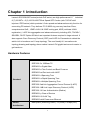


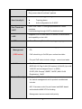

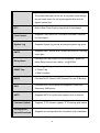


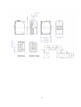
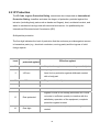

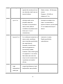
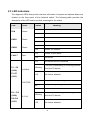


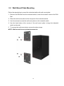
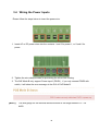
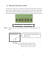
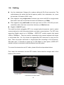


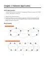
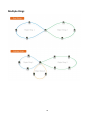

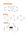

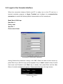

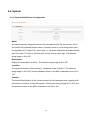
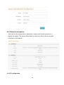

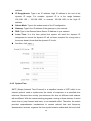
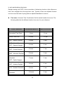

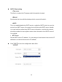


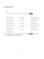
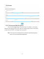


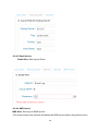

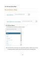
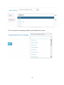
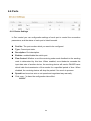


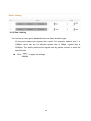
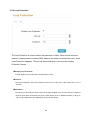
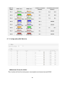
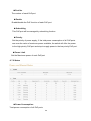

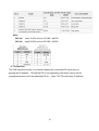
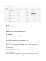


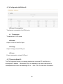

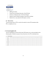

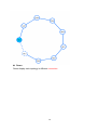


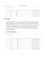


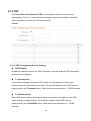
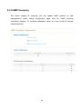
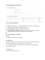
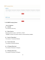


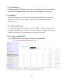
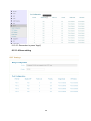


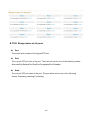

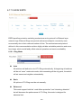


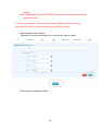
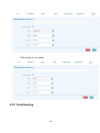


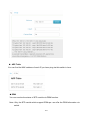
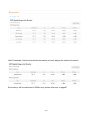


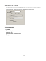
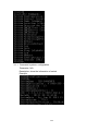


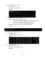

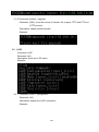
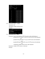
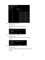
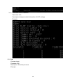

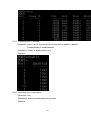
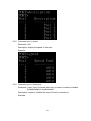

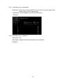


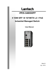
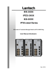


![[Proxyview]User`s Manual (5.1.4.0)](http://vs1.manualzilla.com/store/data/005658349_1-e7f841297d622d23913e7f3fcabf599d-150x150.png)