1
[
S_FA/ PS
OWNER'S
MANUAL
MODEL NO,
917.255430
12.5 HP IC
ELECTRIC START
42" MOWER
6 SPEED TRANSAXLE
LAWN TRACTOR
Caution:
Read and follow
alnlS_nfe_YuRtU
Io_s
• Assembly
• Operation
• Customer Responsibilities
• Service and Adjustment
• Repair Parts
m
L
i
iiiiiii
ii
iii
iiil,lm
Ul
Pml,
IH_H_m
Sears, Roebuck and Co., Hoffman Estates, IL 60179 U.S.A.
SAFETY
Practices RULES
for Ride-On
Safe Operation
Mowers
IMPORTANT: THIS CUTTING MACHINE IS CAPABLE OFAMPUTATING HANDS AND FEETAND THROWING OBJ ECTS.
FAILURE TO OBSERVE TH E FOLLOWING SAFETY INSTRUCTIONS COULD RESULT IN SERIOUS INJURY OR DEATH.
I.
GENERAL OPERATION
Iil.
•
Read understand, and fellow all instructionsinthe manual
and on the mach ne before starting,.
Only allow responsible adults who are familiar with the
instructone, to operate the roach ne.
Clear the area of objects such as recks toys wire etc.,
which could be picked up and thrown by the blade.
Be surer he area isclear of other people before mowing. Stop
machine if anyone enters the area.
Never carry passengers,.
Do not mew in reverse unless absolutely necessary, Always
look down and behind before and while backing.
Be aware ef the mower discharge direction and do not point
it at anyone. Do net operate the mower without either the
entire grass catcher or the guard in place,
Slow down before turning.
Never teave a running machine unattended. Always turn off
blades, set parking brake, step engine, and remove keys
before dismounting.
Turn off blades when not mowing.
Stop engine before removing grass catcher or unclogging
chute,
Tragic accidents can occur if the operator is not alert to the
presenceof chitdren_Children are often attractedte the machine
and the mowing act_vity. Neverassume that children will remain
where you lastsaw them_
•
o
•
•
•
•
•
°
°
o
°
=
o
o
Mew only in daylight er good artificial light.
Do not operate the machine while under the influence of
alcohol or druge_
Watch for traffic when epersting near or creasing roadways°
Use extra care when loading or unloading the machine into
a trailer er truck,
•
CHILDREN
Keep children out of the mowing area and under the watchful
care of another responsible adult.
Be alert and turn machine off if children enter the area.
•
•
Before and when backing, look behind and down for small
children.
-
Never carry children. They may fall off and be seriously
injuredor interfere with safe machine operation.
Never allow children to operatethe machine.
Use extra care when approaching blind corners, shrubs,
trees, or other objects that may obscure vision°
•
•
IV. SERVICE
°
Use extracare in handling gasoiine and other fuels. They are
flammableand vapors are explosive_
Use only an approved container.
Never remove gas cap or add fuel with the engine
running° Allow engine to cool before refueling. Do not
smoke.
Never refuel the machine indoors.
Never stere the machine or fuel container insidewhere
there is an open flame, such as a water heater.
Never run a machine insidea closed area°
•
•
Keep nuts and belts especiaUyblade attachment belts, tight
and keep equ pment in good conditiom
Never tamper with safety devices. Check their proper
operation regularly,
Keep machine free of grass leaves orotherdebrisbuiid-up.
Ctean oil or fuel spillage. Allow machine to cool before
storing.
Step and inspect the equipment if you strike an object.
Repair, ifnecessary, before restarting.
Never make adjustments or repairs with the engine running,.
Grass catchercomponents are subject to wear, damage, and
deterioration, which could expose moving parts or allow
objects te be thrown, Frequently check components and
replace with manufacturer's recommended partslwhen necessary.
Mower blades are sharp and can cut. Wrap the blade(s) or
wear gloves, and usa extra caution when servicingthem,
Check brake operation frequently. Adjust and service as
required°
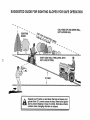
I1. SLOPE OPERATION
Slopes are a majorfactor related to loss-of-control and tipover
accidents, which can result in severe injury er death. All slopes
raquire extra caution. Ifyou cannotback up the slope or ifyou feel
uneasy on it, do not mow it.
DO:
Mew up and down slopes, not across,.
Remove obstacles such as recks, tree limbs, etc.
Watch for holes, ruts, or bumps° Uneven terrain could
overturn the machine. Tall grass can hide obetacles_
•
Use slew speed. Choose a low gear sothat you will not have
to step er shift while on the slope.
.
Follow the manufacturer's recommendations for wheel
weights or counterweights to improve stabiiity_
•
Use extra care with grass catchers or ether attachments.
These can change the stability of the machine.
°
Keep all movement on the slopes slewand gradual Do not
make sudden changes in speed or direction..
,
Avoid starting or stepping on a slope. If tires lose traction,
disengage the blades and proceed slowly straight down the
slope..
DO NOT:
•
•
o
\
o
\\
°
°
•
o
•
•
•
Do not turn on slopes unless necessary, andthen, turn slowly
and gradually downhill, if possible.
DOnot mew near drep-offs, ditches, or embankments. The
mower could suddenly turn over if a wheel is over the edge
of a cliff er ditch, er if an edge caves in.
Do not mow on wet grass,. Reduced traction could cause
sliding.
Do not try to stabilize the machine by putting your foot on the
ground
Do net use grass catcher on steep slopes..
•
•
•
=
ii= i
=
I,H
,
tant safety precautions,
it means
Look for this BECOME
symbol to ALERT!!!
point out imporCAUTION!!!
YOUR
SAFETY IS INVOLVED.
IIHll
H
,i,,
CAUTION:
Always
disconnect
spark
contact
plug wire
in order
plug wirespark
and place
whereto itprevent
cannot
accidental startinl] when setting up,
transporting,
adjusting
or making
repmrs.
PRODUCT
CONGRATULATIONS
on your purchase of a Sears
. _'ractor, It has been designed, engineered and manufi_ctured to give you the best possible dependability and
r_erformance.
_hould yeu experience any problem you cannot easily
remedy, p_ease contact your nearest Sears Service
Department.
We have competent, well-trained technicians and the proper tools to service or repair this unito
Please read and retain this manual. The instructions will
enable you to assemble and maintain your unit properly.
Always observe the "SAFETY RULES
MODEL
NUMBER
SPECIFICATIONS
HORSEPOWER:
I2,5
GASOLINE CAPACITY:
5 QUARTS
UNLEADED REGULAR
OIL (3.0 PINTS):
SAE 30 (Above 32°F)
5W-30 (Below 32°F)
SPARK PLUG (GAP 030 tN ):
CHAMPION RJ-19LM
STD361458
VALVE CLEARANCE:
INTAKE .005 - .007 IN o
EXHAUST °009 - .011 IN
GROUND SPEED:
FORWARD
1st 1.10 MPH
2nd 1.40 MPH
3rd 2 00 MPH
4th 3 00 MPH
5th 420 MPH
6th 5.00 MPH
REVERSE: 1 50 MPH
TIRE PRESSURE:
FRONT: 14 PSI
REAR: 12 PSI
CHARGING SYSTEM:
3 AMPS BATTERY
5 AMPS HEADLIGHTS
BLADE BOLT TORQUE:
30-35 FToLBS
9t7.255430
SERIAL
NUMBER
DATE OF PURCHASE
THE MODEL AND SERIAL NUMBERS WILL BE FOUND
ON A PLATE UNDER THE SEAT.
YOU SHOULD RECORD BOTH SERIAL NUMBER AND
DATE OF PURCHASE AND KEEP IN A SAFE PLACE
FOR FUTURE REFERENCE.
MAINTENANCE
AGREEMENT
WARNING: This unit is equipped with an internal combustion engine and should not be used on or near any unimproved forest-covered, brush*covered or grass-covered
land unless the engine's exhaust system is equipped with
a spark arrester meeting applicable local or state Iaws (if
any)° If a spark arrester is used, it should be maintained in
effective working order by the operator°
tn the state of California the above is required by law
(Section 4442 of the California Public Resources Code)_
Other states may have similar tawso Federal laws apply on
federal lands. A spark arrester for the muffler is available
through your nearest Sears Authorized Service Center
(See REPAIR PARTS section of this manual).
A Sears Maintenance Agreement is available on this product. Contact your nearest Sears store for details.
CUSTOMER
RESPONSIBILITIES
•
Read and observe the safety ruleso
•
Fellow a regular schedule in maintaining, caring for and
using your unit,
Fellow the instructions under "Customer Responsibilities" and "Storage" sections of this owner's manual.
°
LIMITED TWO YEAR WARRANTY
ON ELECTRIC
START RIDING EQUIPMENT
For two (2) years from the date of purchase, if this riding equipment is maintained, lubricated and tuned up according to the
instructions in the owner's manual, Sears wifi repair or replace, free of charge, any parts found to be defective in material or
workmanship,
This Warranty does not cover:
•
°
•
•
Expendable itemswhich become worn during normal use, such as blades, spark plugs, air cleaners and belts
Tire replacement or repair caused by punctures from outside objects, such as nails, thorns, stumps, or glass.
Repairs necessary because of operator abuse, negligence, improper storage or accident or the faiiure to maintain the
equipment according to the instructionscontained in the owner's manuai.
Riding equipment used for commercial or rental purposes
LIMITED 90 DAY WARRANTY
ON BA'i'rERY
For 90 days from date of purchase, if any battery included with this riding equipment proves defective in material or workmanship
and our testing determines the battery will not hold a charge, Sears will reptace the battery at no charge.
WARRANTY SERVICE IS AVAILABLE BY RETURNING
CENTER/DEPARTMENT
IN THE UNITED STATES
THE RIDING
EQUIPMENT
TO THE NEAREST
SEARS SERVICE
This Warranty gives you specific legal rights, and you may also have other rights which may vary from state to state
SEARS, ROEBUCK AND CO., D/817 WA, HOFFMAN ESTATES, ILLINOIS 60179
, =HH
n'
,'1,
nHHn,,nm=
3
=,n'
TABLE OF CONTENTS
SAFETY RULES ............................................................
2
PRODUCT SPECIFICATIONS ....................................... 3
CUSTOMER RESPONSIBILITIES ..................... 3, 14-17
WARRANTY ...................................................................
3
TABLE OF CONTENTS ................................................. 4
INDEX .............................................................................
4
TRACTOR ACCESSORIES ........................................... 5
ASSEMBLY ................................................................
7-9
MAINTENANCE SCHEDULE ......................................
SERVICE AND ADJUSTMENTS ............................ 18-_
REPAIR PARTS - TRACTOR ................. ;............... 28-,_:___
REPAIR PARTS - ENGINE ..................................... 4_
PARTS ORDERING/SERVICE ................... BACK PA_=_
INDEX
E
A
Accessories ............................................
5
Adjustments:
Brake ............................................
20
Carburetor ........................................23
Mower
Front*To-Back ......................... 19
Side-To-Side ........................... 19
Throttle Control Cable ................. 23
Air Filter, Engine ................................... 16
Air Screen, Engine ................................ 17
Assembly
7-9
..................................................
B
Battery:
Charging ............................................. 8
Cieaning ....................................... 15
Installation ........................................ 9
Levels .......................................
8,15
Preparation ...................................... 8
Starting with Weak Battery .......... 21
Storage .......................................... 24
Terminals ....................................... ! 5
Belt:
Motion Drive
Removal/Replacement
Mower Blade Drive
........... 20
Removal/Replacement
.............20
Blade:
Electrical:
Interlocks and Relays .................. 22
Schematic ........................................ 27
Wiring Diagram ..................................
28
Engine:
Air Filter ........................................ 16
Air Fitter Foam Pre-Cieaner ..........16
Air Screen ........................................ 17
Cooling Fins, Engine ........................
17
Oil Change .........................................
16
Oil Level .......................................12,16
Oil Type .............................................16
Preparation ........................................12
Repair Parts ..................................
44-48
Stadin g ............................................. 13
Storage .......................................... 24
r
Filter:
Air Filter .......................................... 16
Air Filter Foan 're-Cleaner ........ 16
Fuel .............................................. 17
Fuel:
Type .......................................................
t2
Storage ............................................ 24
Fuse .....................................................
22
H
Hood Removal/installation
Sharpening ..................................... 15
Replacement ................................. 15
Brake Adjustment ................................ 20
C
.................... 22
L
Leveling Mower Deck ............................ 19
Lubrication:
Chart
14
....................................................
Carburetor Adjustment ....................... 23
Controls, Tractor .................................... 10
Customer Responsibilities .....................
14-17
Engine:
Air Filter ........................................ 16
Air Filter Foam Pro-Cleaner .... 16
Air Screen, Engine .................. 17
Batter,.#........ :............................ 15
...........
Cooling Fins, Engine ................ 17
Engine Oil ................................ 16
Fuel Filter ................................ 17
Spark Plugs .............................. 17
Tractor:
Blade .......................................... 15
Lubrication Chart ..................... 14
Maintenance Schedule ............. t 4
Fire Care ........................... 8,15,21
Cutting Height, Mower
11
...........................
M
Maintenance Schedule ................................
14
Mower:
Adjustment, Front4o-Back .............19
Adjustment, S}de4o-Side ............. t9
Blade Sharpening .......................... 15
Blade Replacement ...................... 15
Cutting Height ............................... 11
.... tnstallatidri _,, ,,;:- _._--..-,, r_.o_..__._l-8 Operation ....................................... 12
Removal ...................................... 18
Mowing Tips ......................................... 13
Muffler ...................................................... t 7
Spark Arrestor ........................... 3,38
0
Oil:
Cold Weather Conditions ....... 12,16
Engine ............................................ 16
Storage .............................................24
4
Operation ......................................
10-1
Operating Mower ....: ........................... 1
Options:
Accessories ..................................... 5
Spark Arrester .......................... 3,3 8
P
Parking Brake ................................. t0-1 1
Parts Bag ..............................................
6
Pads, Replacement/Repair
............ 28-4._
Product Specifications ........................... _E_
R
Repair Parts ...................................... 28-4.,_
S
Safety Rules ............................................. 2
Seat .......................................................
8
Service and Adjustments .............. 18-23
Carburetor ................................... 213
Fuse .............................................. 21_
Hood Remova!/Instaliation
.......... 22
Motion Drive Belt
Removal/Replacement
Mower Blade Drive Belt
........... 20
Removal/Replacement
........... 20
Mower Adjustment
Front- to-Back ........................ 19
Side-to-Side ............................ 19
Mower Removal .......................... 18
Tire Care ............................. 8,15,21
Slope Guide Sheet ............................. 51
Spark Plugs .........................................
17
Specifications .......................................
3
Starting the Engine ........................ 12-13
Steering Wheel ................................. 7,21
Stopping the Tractor ............................ 11
Storage ................................................
24
T
Throttle Control Cable
Adjustment ...................................
23
Tires .................................................... 8,15,21
Troubleshooting Chart .................... 25-26
Transaxle:
Repair Parts ........................... 42-43
W
Warranty ................................................
Wiring Diagram ...................................
Wiring Schematic ...............................
3
28
27
Jiiiiil,lll,,
,
i i,,i ,,i, iii
i lrllll
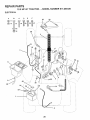
ACCESSORIES
,
i, ,11
i
iii
ii iiii
AND ATTACHMENTS
...........................
iii i,i i,,111
, ,,,,, ,,,,,,,
"Theseaccessories and attachments wereavailable when the tractor was purchased_They are also available at most Sears retail outlets,
"catalog and service centers. Most Sears stores can order these items for you when you provide the model number of your tractor°
MAINTENANCE
ENGINE
SPARKPLUG
MUFFLER
AIRRLTER
GASCAN
ENGINEOIL
STABILIZER
BLADES
BELTS
%
PERFORMANCE
Sears offers a wide variety of attachments that tit your tractor. Many of these are listed below with brief explanations of how they can help
you_ This list was current at the time of publication; however, it may change in future yea[s - more attachments may be added, changes
may be made in these attachments, or some may no longer be available or fit your model Contact your nearest Sears store for the
accessories and attachments that are available for your tractor.
Most of these attachments do not require additional hitches or conversion kits (those that do are indicated) and are designed for easy
attaching and detaching,
PERMANEX BAGGER lets you collect grass clippings and
leaves for a healthier, neater looking lawn. Two Permanex
containers hold 30-gallon plastic bags°
LAWN SWEEPERS let you collect grass clippings and Ieaves.
LAWN VAOS for powerful collection of heavy grass clippings and
leaves. Wand attachment to pick up debris in hard-to-reach
ptaces_
CARTS make hauling easy° Vadety of sizes available_
ROLLER for smoother lawn surface. 36-inch wide, 18-inch
diameter water-tight drum holds upto 390 Ibs,.of weight,.Rounded
edges prevent harm to turf. Adjustable scraper automatically
cleans drum.
SPREADERISEEDERS make seeding, fertilizing, and weed
killing easy. Broadcast spreaders are also useful for granular
de-icers and sand.
CORING AERATOR takes small plugs out of soit to allow moisture and nutrients to reach grass roots° 36-inch swath. 24
hardened steei coring tips° 150 lb, capacity weight tray.
AERATOR promotes deep root growth for a healthy lawn. Tapered 2,.5-inch steel spikes mounted on 10-inch diameter discs
puncture holes in soil at close intervalsto let moisture soak in.
Steel weight tray for increasedpenetration.
MULCH RAKE/DErHATCHER loosens soil and flips thatch and
matted leaves to lawn surface for easy pickup, Twenty spring line
teeth. Usefutto preparebareareasforseeding. Avaitableforfront
or rear mounting,
SPRAYERS use 12-volt DC electric motor that connects to the
tractor battery or other 12-volt source. Includes booms for
automatic spraying when pulling and hand held wand for spot
spraying. Wand has adjustabfe spray pattern. For applying
herbicides, insecticides,fungici_Sl and_liCl_idfertilizers.
SNOW BLADE for snow removal only. 14-inch high, 42-inch
w de blade clears 38-inch path when angled left or right. Raises,
lowers with side lever° Adjustable skids; replaceable, reversible
scraper bar. (Use with tire chains, wheel weights, or rear drawbar
weight.)
SNOW'rHROWERhas 40-inch swath. Drum-type auger handles
powdery and wet/heavy snow. Mounts easily with simple pin
arrangement, Discharge chute adjusts from tractor seat° 6-inch
diameter spout discharges snow 10 to 50 feet. L_t controlled at
tractor seat. (Use with chains, wheel weights, or rear drawbar
weight,)
TIRE CHAINS are heavy dutyi closely spaced extra-large cross
linksgive smooth ride,outstanding traction.
WHEEL WEIGHTS for rear wheels provide needed traction for
snow removalor dozing heavy materials, in pairs_ (30 lbs..each.)
TRACTOR CAB has heavy duty vinyl fabric over tubular steel
frame, ABS plastic top; clear plasticwindshield offers 360 degree
visibility. Hinged metal doors with catch. Keeps operator warm
and dry. Remove vinyl and windshields for use as sun protector
in summer. (Catalog only_)
Optional accessories for tractor cab: tinted/tempered solid
safety glass windshield with hand operated wiper; 12-volt amber
cautionlightfor mounting on cab top_ (Catalog only.)
TRACTOR COVER protects tractor from weather. Made of
Evolution 3 fabric (water-repellent, extremely breathable, light
weight soft non-abrasive, pliable in all temperatures, durable,
stain/tear/puncture res stant, wi not shr nk or stretch.) (Catalog
only.)
TILLER has 5 hp engineand 36-inch swath to prepare seed beds,
cult{vale, and compost garden residue, Tiller has itsown built-in
lift and depth control system and does NOT require a sleeve hitch.
Fits any lawn, yard, or-gardentract0r_ Simply hook [_pto the
tractor drawbar and go!
Ul
i
.... i1,1,
n
.....
CONTENTS OF
PAC
Parts Bag contents shown full size
Parts packed separately in carton
i
,lUUlninnl
I
÷
©
Battery acid
Steering
Wheel
(1) Loeknut 3/8-24
(1) Large Flat Washer
Battery
Steering
Boot
Owner's Manual
(1) Shoulder Bolt 5/16-18
('1) Hex Bolt t/2q3
t
I
I
I
E
I
E
I
I
I
=
I
Parts Bag
x 't
(¢
Parts bag contents not shown full size
'
_
"
_L_
Steering Wheel
Adapter
(1) Lock Washer 1/2
(1) Washer
i'----
Seat
(2) Sheet
Metal
Screws
#10-16 x t/2
II_)l!
Wheel
Steering
Insert
17/32 x 1-3/16 x 12 Gauge
0
i1,1.
...............
@
(2) Hex Bolts 1/4-20 x 3/4
(2) Keys
Steering
Bushing
I
(2) Hex Nuts 1/4-20
t
I
(2) Lock Washers
(2) Washers
1/4
15 ° Slope Sheet
9/32 x 5/8 x 16 Gauge
iii
un,ll,
I
Ba_eecaps "
and Instructions
i1,11
.....................
i,
nunlHl"l'll"l'l
i
i i
i, ,iqll
ASSEMBLY
'.'our new tractor has been assembled at the factory with exce
n of those parts left unassembIed for shipping pu rposes.
To ensure safe and proper operation of your tractor, atl parts and hardware you assemble must be tightened securely. Use
the correct tools as necessary to insure proper tightness,
TOOLS REQUIRED
FOR ASSEMBLY
INSERT
A socket wrench set will make assembly easier. Standard
wrench sizes are listed,
(1) 5/16" wrench
9/16" wrench
(2) 7/16" wrenches
Screwdriver
(t)
Utility knife
1/2" wrench
(1) 3/4" wrench
3/8-24HEXLOCKNUT
_
Tire pressure gauge
_
When right and left hand is mentioned in this manual, it
means when you are in the operating position (seated
behind the steering wheel).
TO REMOVE UNIT FROM CARTON
UNPACK
ST EERIN G-_..._
WHEEL
STEERING_
°
Cut from top to bottom, alonglinesonatlfourcorners
of carton and lay pane s flat.
°
Check for any additional loose parts or cartons and
remove°
ATTACH
STEERING
WHEEL
BOOT
STEERING
(ASSEMBLY
POSITION)
TABS
f_/iJ
TAB
HOLE
(See Fig, 1)
Slide the steering bushing over the steering shaft.
o
Raise steering shaft forward until screw holes in dash
line up with steering bushing, install two (2) sheet
metal screws and tighten securely.
•
Position steering boot over steering shaft.
.
Place tabs of steering boot over tab slots in dash and
push down to secure.
°
Slide steering wheel adapter onto upper steering shaft,,
°
Position front wheels of the tractor so they are pointing
straight forward,
°
Position steering wheel so cross bars are horizontal
(left to right) and slide onto adapter.
°
Assemble large flat washer and 3/8-24
tighten securely.
°
Snap steering wheel insert into center of steering
wheel.
Iocknut and
.
Remove protective plastic from tractor hood and grill.
IMPORTANT:
CHECK
FOR AND REMOVE
ANY
STAPLES 1NSKID THAT MAY PUNCTURE TIRES WHERE
UNiT iS TO ROLL OFF SKID.
TO ROLL UNIT OFF SKID (See Fig. 6)
°
Raise attachment tift lever to its highest position,
°
Release parking brake by depressing clutchtbrake
pedal,
Place gearshift lever in "NEUTRAL" position,
Roll unit backwards off skid.
°
SCREW
UNYT OFF SKID
°
.
•
_,_..
t'_
Remove all accessible loose parts and parts cartons
from carton (See page 6).
ROLLING
STEERINGWHEEL
ADAPTER
_.
CARTON
•
BEFORE
LARGEFLATWASHER
Remove banding holding discharge guard up against
tractor,
//
/,
STEERINGSHAFT .........., ,
(SHIPPINGPOSITION)
.....
FIG. 1
t
SLOT
BLY
HOW TO SET UP YOUR TRACTOR
INSTALL SEAT (See Fig. 3)
Adjust seat before tightening adjustment bolt.
PREPARE BATI'ERY (See Fig. 2)
iiill N, ,ll,i
ii ii
CAUTION:
Wear eye and face shield.
Wash hands or clothing immediately if
accidentally in contactwith battery acid.
,
•
Remove cardboard packing on seat pan.
Place seat on pan and assemble shoulder bolt
°
Assembleadjustment bolt, Iockwasherand
Ioosely_ Do not tighten_
•
Tighten shoulder bolt securely
Do
not acid
smoke.
Fumes from charged
battery
are explosive.
•
Lower seat into operating position and sit on seat°
Read the instructionsincluded with the
battery vent caps. Always wear gloves,
clothing and goggles to protect your
hands, skin and eyes.
°
Slide seat untila comfortable position is reached which
allows you to press clutch/brake pedal all the way down
(See Fig., 6),
•
°
Get off seat without moving its adjusted position.
Raise seat and tighten adjustment bolt securely°
Your unit has a battery charging system which is sufficient
for normal use. However, periodic charging of the battery
with an automotive charger will extend its life.
•
See instructions packed with vent caps in parts bag.
-
Fill battery with acid Fill each cell until it reaches the
bottom of the vent wells Do not overfill
-
Allow battery to stand and settle for at least thirty
minutes. After standing, check the level of acid_ If
below the vent wells, add more acid until the correct
level is reached.
SEAT
SEAT PAN
SHOULDER
BOLT
While battery is standing (after adding acid) and later, while
battery is being charged, continue with assembly of unit°
IMPORTANT:
TO MAXIMIZE THE LIFE OF YOUR
BATTERY, IT IS NECESSARY THAT THE BATTERY BE
CHARGED
BEFORE USE. FAILURE TO CHARGE
BATTERY CAN RESULT IN A SHORTENED BATTERY
LIFE..
•
ADJt
BOLT
Charge battery at a rate of 6 amperes for 1 hour., Use
a 12 volt battery charger. Observe all safety precautions required for battery charging.,
•
Check the acid level after the battery is charged, If the
acid has fallen below the correct level, add distilled or
iron free water.
°
Install the vent caps to cover the vent wells,. Wash the
top of the battery with water to remove any acid, then
wipe dry,
o
Check battery case for leakage to make sure that no
damage has occurred in handling.
,
Dispose of excess battery acid_ Neutralize acid for
disposal by adding it to four inches of water in a five
gallon plastic container. Stir with a wooden or plastic
paddle while adding baking soda until the addition of
more soda causes no more foaming.
•
flat washer
FIG. 3
CHECK TIRE PRESSURE
The tires on your unit were overinflated at the factory for
shipping purposes_ Correct tire pressure is important for
best cutting performance.
•
Reduce tire pressure PSI shown in"PRODUCT
FICATION on page 3 of this manual
SPECI-
CHECK DECK LEVELNESS
For best cutting results, mower housing should be properly
leveled. See "TO LEVEL MOWER HOUSING" in the
Service and Adjustments section of this manual
CHECK
Follow instructions on how to install batte_: ".................
CUT AWAY VIEW
FOR
PROPER
POSITION
OF
ALL
See the figures that are shown for replacing motion and
mower blade drive belts in the Service and Adjustments
section of this manual. Verify that the belts are routed
correctly°
VENT WELL
BATTERY
CELLAClD
LEVEL
CHECK BRAKE SYSTEM
After you learn how to operate your tractor, check to see
that the brake is properly adjusted_ See "TO ADJUST
BRAKE" in the Service and Adjustments section of this
manual.
FIG. 2
8
iii
..........i
.....................
n
,,,
,,,, i_ i i,,,
ASSEMBLY
,i
INSTALL
....
BATTERY
i1,11,1,
(See Figs. 4 & 5)
.........................
i
i,ii iii,
CAUTION: Do not short battery terminals. Before installing battery, remove
metal bracelets, wristwatch bands,
rings, etc.
Positive terminal must be connected
first to prevent sparking from accidental grounding.
.................
ii
,,,
•
Lift seat to raised position.
•
Open battery box door°
•
Be sure battery drain tube is attached to battery box.
•
Lower battery into battery box with battery terminals
toward front of unit.
•
First connect RED battery cable to positive (+) battery
terminal with hex bolt, flat washer, lock washer and hex
nut as shown° Tighten securely.
°
Connect BLACK grounding cable to negative (-) battery terminal with remaining hex bolt, flat washer, lock
washer and hex nut. Tighten securely_
•
Close battery box door.
BATTERY
BOX
VENT CAPS
FIG. 5
Open battery box door for:
-
inspection
ware).
for secure connections
(to tighten hard-
•
Inspection for corrosion.
°
Testing battery.
•
Jumping (if required)°
BEFORE YOU OPERATE AND ENJOY YOUR NEW
TRACTOR, WE WISH TO ASSURE THAT YOU RECEIVE
THEBESTPERFORMANCEAND
SA TISFACTION FROM
THIS QUALITY PRODUCT,
•
Periodic charging.
PLEASE REVIEW THE FOLLOWING CHECKLIST,"
BATTERY
BOX DOOR
(NEGATIVE)
BLACK
GROUNDING
CABLE
,/CHECKLIST
,/
All assembly instructions have been completed.
J'
No remaining loose parts in carton°
#"
Battery is properly prepared and charged.
1 hour at 6 amps).
,/
Seat is adjusted comfortably and tightened securely.
,/
All tires are properly inflated. (For shipping purposes,
the tires were overinftated at the factory).
•/
Be sure mower deck is properly leveled side-to-side!
front-to-rear for best cutting results. (Tires must be
properly inflated for leveling),
(Minimum
V" Check mower and drive belts. Be sure they are routed
properly around pulleys and inside all belt keepers.
,/
Check wiring. See that all connections are still secure
and wires are properly clamped.
WHILE LEARNING HOW-TO USE YOUR TRACTOR, PAY
EXTRA ATTENTION TO THE FOLLOWING IMPORTANT
ITEMS:
#'
Engine oil is at proper level.
,/
Fuel tank is filled with fresh, clean, regular unleaded
gasoline.
Become familiar with atl controls - their location and
function. Operate them before you start the engine.
,/
POSITIVE(+) TERMINAL
NEGATIVE(-) TERMINAL
FIG. 4
,/
Be sure brake system is in safe operating condition.
OPERATION
KNOW YOUR TRACTOR
READ THIS OWNER'S MANUAL AND SAFETY RULES BEFORE OPERATING YOUR TRACTOR
Comparethe i__ustrati_nswithy_urtract_rt_fami_iarizey_ur_e_fwiththe__cati_ns_fvari_us__ntr__sandadjustments`
this manual for ftdure reference°
A'I'rACHMENT
CLUTCH LEVER
IGNITION
SWITCH
Save
UFT LEVER
PLUNGER
A'n'ACHMENT
LIFT LEVER
UGHT SWITCH
THROTTLE/CHOKE
CONTROL
CLUTCH/BRAKE
MOWER DECK
HEIGHT ADJUSTMENT
POSITIONS
PARKING
GEARSHIFT
LEVER
FIG. 6
Sears tractors conform to the safety standards of the American National Standards Institute.
ATTACHMENT CLUTCH LEVER: Used to engage the
mower blades, or other attachments mounted to your
tractor°
GEARSHIFT LEVER; Selects the speed and direction of
tractor.
ATTACHMENT LIFT LEVER: Used to raise, lower, and
adjust the mower deck or other attachments mounted to
your tractor.
LIFT LEVER PLUNGER: Used to release attachment lift
LIGHT SWITCH: Turns the headlights on and off.
THROTTLE/CHOKE
CONTROL: Used for starting and
controlling engine speed.
CLUTCH/BRAKE PEDAL: Usedfor declutching and brak..
ing the tractor and starting the engine,.
PARKING BRAKE:
brake position.
Locks clutch/brake
lever when changing its position°
IGNITION SWITCH:Used
forstartingana
engine,
pedal into the
10
st615pliigthe
The operation of any tractor can result in foreign objects thrown into the eyes, which can
result in severe eye damage.. Always wear safety .glasses or eye shields while operating
your tractor or performing any adjustments or repairs. We recommend wide vision safety
mask for over the spectacles or standard safety glasses, available at Sears Retail or
Catalog stores,
HOW TO USE YOUR TRACTOR
NOTE: Under certain conditions when unit is standing idle
with the engine running, hot engine exhaust gases may
cause "browning" of grass.. To eliminate this possibility,
always stop engine when stopping unit on grass areas.
TO SET PARKING BRAKE (See Fig. 7)
•
Depress clutch/brake pedal into full "BRAKE" position
and hold.
•
Place parking brake lever in "ENGAGED" position and
releasepressure from clutch/brake pedal Pedalshould
remain m "BRAKE" positiOn.r Make sure parking brake
will hold vehicle secure°
ATTACHMENT CLUTCH LEVER
"ENGAGED" POSITION
i ii :::::::::::::::::::::::
as described above, before leaving the
operator's
position; to empty grass
CAUTION;
Alwaysstop unitcompletely,
catcher, etc,
i&
n
"DISENGAGED"
POSITION
i i ,,, ,, ,i,,,
u ::::::::::::::::::::::
H H, i,,i,
TO USE THROTTLE CONTROL (See Fig. 7)
Always operate engine at full throttle°
•
Operating en_]ine at less than full throttle reduces the
battery charging rate,
•
Full throttle offers the best bagging and mower performance,,
TO MOVE FORWARD
AND BACKWARD
(See
Fig. 6)
PARKING
BRAKE
"ENGAGED"
The direction and speed of movement is controlled by the
gearshift lever..
.GEARSHIFT
LEVER
°
Start tractor with clutch/brake pedal depressed
gearshift lever in "NEUTRAL" position.
•
Move gearshift lever to desired
and
position..
°
Slowly release clutch/brake pedal to start movement..
IMPORTANT: BRING TRACTOR TO A COMPLETE STOP
BEFORE SHIFTING OR CHANGING GEARS. FAILURE
TO DO SO WILL SHORTEN THE USEFUL UFE OF YOUR
TRANSAXLEo
TO ADJUST MOWER CUTTING HEIGHT (See
Fig. 6)
POSITION
CLUTCH/BRAKEPEDAL PARKINGBRAKE
"DRIVE" POSITION
"DISENGAGED"POSITION
The position of the attachment lift lever determines
cutting height.
FIG. 7
the
STOPPING (See Fig. 7)
°
Grasp lift lever°
MOWER BLADES -
°
Press plunger with thumb and move lever to desired
position,
o
Move attachment clutch lever to "DISENGAGED"
sition.
po-
The cutting height range is approximately 1-1/2 to 4". The
heights are measured from the ground to the blade tip with
the engine not rUnning. These heights are approximate ....
and may vary depending upon soil conditions, height of
grass and types of grass being mowed°
GROUND DRIVE ................
•
Depress clutch!brake pedal into full "BRAKE" position.
•
Move gearshift
ENGINE =
lever to "NEUTRAL" position,
The average lawn should be cut to approximately
2-1/2 inches during the cool season and to over 3
inches during hot months. For healthier and better
looking lawns, mow often and after moderate growth°
•
For best cutting performance, grass over 6 inches in
height should be mowed twice° Make the first cut
relatively high; the second to desired height.
Move throttle control to "SLOW" position..
NOTE; Failureto move throttle control to "SLOW" position
and allowing engine to idle before stopping may cause
engine to "backfire".
•
Turn ignition key to "OFF" position and remove key.
Always remove key when leaving vehicle to prevent
unauthorized use.
•
•
Never use choke to stop engine.
11
OPERATIO
......................................
i
TO OPERATE
,
i
MOWER
,
ii,
i
i
i
(See Fig. 8)
Your unit is equipped with an operator presence sensing
switch. Any attempt by the operator to leave the seat with
the engine running and the attachment clutch engaged will
shut off the engine.
o
If stopping is absolutely necessary, push clutch/brake
pedal quickly to brake position and engage parking
brake,
°
Move gearshift lever to 1st gear and be sure you have
allowed room for tractor to roll slightly as you restart
movement.
•
Select desired height of cut.
-
Start mower blades by engaging attachment
control°
clutch
°
'To restart movement, slowly release parking brake and
clutch/brake pedal
o
TO STOP MOWER BLADES- Disengage attachment
clutch control.
•
Make all rums slowly.
_)
TO TRANSPORT
without either the entire grass catcher,
operate or
the the
mower
onAUTION:
mowers Do
so not
equipped,
discharge guard in place.
ATTACHMENT CLUTCH LEVER
"DISENGAGED" POSITION
"ENGAGED"
POSITION
•
Raise attachment lift lever to highest position.
°
When pushing or towing your unit, be sure gearshift
lever is in "NEUTRAL" position.
°
Do not push or tow unit at more than five (5) MPH.
BEFORE
ATTACHMENT
LIFT LEVER
HIGH POSITION
STARTING
THE ENGINE
CHECK ENGINE OiL LEVEL (See Fig. 13)
LOW
POSITION
°
The engine in your unit has been shipped, from the
factory, already filled with summer weight oil.
°
Check engine oil with unit on level ground.
•
Remove oil fill dipstick and wipe clean, replace and
screw cap tight, wait for a few seconds, remove and
read oil level If necessary, add oil until "FULL" mark
on dipstick is reached. Do not overfill°
°
For cold weather op,?,rationyou should change oil for
easier starting (see ' OIL VISCOSITY CHART' in the
Customer Responsibilities section of this manual)
=
To chan_e engine oil, see the Customer Responsibilities section in this manual.
ADD GASOLINE
°
Fill fuel tank. Use fresh, clean, regular unleaded
gasoline. (Use of leaded gasoline will increasecarbon
and lead oxide deposits and reduce valve life)o
IMPORTANT:
WHEN OPERATING IN TEMPERATURES
BELOW32°F(0°C), USE FRESH, CLEAN WINTER GRADE
GASOLINE TO HELP INSURE GOOD COLD WEATHER
STARTING
RUNNER
WARNING:
Experience indicates that alcohol blended
fuels (called gaschol or using ethanol or methanol) can
attract moisture which leads to separation and formation of
acids during storage° Acidic gas can damage the fuel
system of an engine while in storage° To avoid engine
problems, the fuel system should be emptied before storage of 30 days or longer. Drain the gas tank, start the
engine and let it run until the fuel lines and carburetorare
empty. Use fresh fuel next season,1 See Storage Instructions for additional information
Never use engine or
carburetor cleaner products in the fuel tank or permanent
damage may occur,
DISCHARGEGUARD
FIG. 8
TO OPERATE
ON HILLS
hills with slopes greater than 15 ° and
I
do not drive across any slope,
!
-
Choose the slowest speed before starting up or down
hills.
°
Avoid stopping or changing speed on hills.
°
If slowing is necessary, move throttle control lever to
slower position.
filler neck. Do not overfill. Wipeoffany
CAUTION:
bottom
of gas
tank
spilled
oil orFill
fuel.to Do
not store,
spill
or
use gasoline near an open flame.
12
I
!J
I
.........
, ,i,,,,,,,,i,
,i, ,,,,,,,,,r,,ll
OPERATION
iii
TO START
ii
ENGINE
i i i,,i,,i .........................................
ii ""Mr
'
'11'1'1
.........I'
L ',,'1
MOWING TIPS
(See Fig. 7)
When starting engine for the first time or if engine has run
out of fuel, it wiil take extra cranking time to move fuel from
the tank to the engine.
°
Depress the clutch!brake
brake.
•
Place gearshift lever in "NEUTRAL" position_
°
Move attachment clutch to "DISENGAGED"
•
Move throttle control lever to "CHOKE" position for
cold engine start, For warm engine start, move throttle
control to "FAST" position_
•
I
•
Tire chains cannot be used when the mower housing
is attached to unit
•
Mower should be properly leveled for best mowing
performance. See "TO LEVEL MOWER HOUSING" in
the Service and Adjustments section of this manual.
•
Use the runner on the right hand side of mower as a
guide. The blade cuts approximately an inch outside
the nJnner (See Fig. 8).
The left hand side of mower should be used for trimming.
pedal and set the parking
position.
•
Insert keyinto ignition and turn key clockwiseto"START"
position and release key as soon as engine starts. Do
not run starter continuously for more than fifteen
seconds per minute. If engine does not start after
several attempts, move throttle control to "FAST position, wait a few minutes and try again.
°
When engine starts, move throttle control to desired
position.
•
Allow engine to warm up for a few minutes before
engaging drive or attachments_
•
Drive so that clippings are discharged onto the area
that has been cut. Have the cut area to the right of the
machine This wilt result in a more even distnbution of
clippings and more uniform cutting.
•
When mowing large areas, start by turning to the right
so that clippings will discharge away from shrubs,
fences, driveways, etc_ After one or two rounds, mow
in the opposite direction making left hand turns until
finished (See Fig. 9)
.................
K
NOTE: If at a high altitude (above 3000 feet) or in cold
temperatures (below 32 ° F), the carburetor fuel mixture
may need to be adjusted for best engine performance. See
"TO ADJUST CARBURETOR" in the Service and Adjustments section of this manual.
,ILI,LI
I I
, II,II
f
.......
:,.: ;,,j
FIG. 9
•
If grass is extremely tall, it should be mowed twice to
reduce load and possible fire hazard from dried clippings. Make first cut relatively high; the second to the
desired height.
°
Do not mow grass when it is wet. Wet grass wilt plug
mower and leave undesirable clumps_ Allow grass to
dry before mowing.
•
Always operate engine at full throttle when mowing to
assure better mowing performance and proper discharge of material. Regulate ground speed by selecting a low enough gear to give the mower cutting
performance as well as the quality of cut desired.
• . When operating attachments, se!.ect a ground speed
that will suit the terrain and give best performance of
the attachment being used.
13
_A'
NTENANCE
SCHEDULE
_____
lr
AS YOU COMPLETE
........
REGULAR SERVICE
_"
_
_
_Y
_,_
SERVICE
DATES
,,,Ch,eok
Brake
Operation
T
R
Check Tire Pressure
if
Check for Loose Fasteners
if
I_
Sh_a_en_en/RepiaceMower Biades
C
Lubrication Chart
_4
..............................,,,,,'
.....
_Check Ba!tery Level/Recharge
'
{if
I_ .............
................._
,
0
Clean Battery and Terminals
6_
R
Check Transmission
t_ #
Cooling
Adjust Blade Belt(s) Tension
,
$f
....
...................
Adjust Motion Drive Belt(s) Tension
,,, ,,,,,,,
,,
:
.........
_
,, _
Change Ea,g,!,n,e,,O,!,!
.........
E
Clean Air Filter
N
Clean Air Screen
G
Inspect Muffler/Spark
V _
_t2,3i
,,
_2,,I
6#_
...............
6#'2
Arrestor
_4'
Replace Oil Filter (if equipped)
"ciean
Ks
:
Check Engine Oil Levef
I
--
1_1,2 ,,,
Engine Cooling Fins
' '
6f2
Replace
Spa,k
PIUg
Replace AirFilter
Paper Cartridge
_2
Replace Fuel Filter
_'
1 - Change mere oltan when operaling under a heavy load or In high ambient
2 - Service more olten when operaling In dlily or dusty condllioos
GENERAL
temperatures,
3 - I! equipped wllh oil tilter, change oil every 50 hours,
4 - Replace blades more o/Len when mowing tn sandy soil,
5 - If equipped wl|h adjustable system
LUBRICATION
RECOMMENDATIONS
The warranty on this tractor does not cover items that have
been subjected
to operator
abuse or negligence.
To
receive full value from the warranty, operator must maintain
tractor as instructed in this manual
CHART
ZK@
(_
BEARING ZERK
Some adjustments
will need to be made
properly maintain your tractor.
periodically
All adjustments
in the Service and Adjustments
section of
this manual should be checked at least once each season..
•
Once a year you should replace the sparkplug,
clean
or replace air filter, and check blades and bells for
wear,, A new spark plug and clean air filter assure
proper air4uel mixture and help your engine run better
and tast longer.
BEFORE
EACH
BEARING ZERK
to
IINE(_)
(_
CLUTCH
PIVOT(S)
USE
•
Check engine oil level,
•
Check brake operation,
•
°
Check tire pressure_
Check for loose fasteners
(_) SAE 30 OR IOW30 MOTOR OIL API * SG
(_) GENERAL PURPOSE GREASE
(_) REFER TO CUSTOMER RESPONSIBILITIES "ENGINE" SECTION
IMPORTANT." DO NOT OIL OR GREASE THE PIVOT POINTS
WHICH HAVE SPECIAL NYLON BEARINGS. VISCOUS LUBRICANTS WILL ATTRACT DUST AND DIRT THAT WILL SHORTEN
THE LIFE OF THE SELF-LUBRICATING
BEARINGS. IF YOU
FEEL THEY MUST BE LUBRICATED, USE ONLY A DRY, POW_
DERED GRAPHITE TYPE LUBRICANT SPARINGLY.
14
PONSiBILiTIES
CUSTOMER
i
HHHH, ,,,H
i
TO SHARPEN BLADE (See Fig. 11)
TRACTOR
Care should be taken to keep the blade balanced° An
unbalanced blade willcause excessive vibration and eventual damage to mower and engine_
= The blade can be sharpened with a file or on a grinding
wheel. Do not attempt to sharpen while on the mower.
° To check blade balance, you will need a 5/8" diameter
steel bolt, pin oracone balancer. (When using acone
balancer, follow the instructions supped with balancer).
°
Slide blade on to an unthreaded portion of the steel bolt
or pin and hold the bolt or pin parallel with the ground.
If blade is balanced, it should remain in a horizontal
position. If either end of the blade moves downward,
sharpen the heavy end until the blade is balanced.
Always observe safety rules when performing any maintenance.
BRAKE OPERATION
If unit requires more than six (6) feet stopping distance at
high speed in highest gear, than brake must be adjusted°
(See "TO ADJUST BRAKE" in Service and Adjustments
section of this manual).
TIRES
•
Maintain proper air pressure in all tires (See "PRODUCT SPECIFICATIONS" on page 3 of this manual),.
°
Keep tires free of gasoline, oil, or insect control chemicals which can harm rubber.
•
Avoid stumps, stones, deep ruts, sharp objects and
other hazards that may cause tire damage-
BLADE
NOTE: Do not use a nail for balancing blade. The lobes of
the center hole may appear to be centered, but are not,
CENTER HOLE
/
/
CARE
For best results mower blades must be kept sharp.
place bent or damaged blades.
BLADE
, ,11
REMOVAL
Re-
(See Fig. 10)
o
Raise mower to highest position to allow access to
blades.
•
Remove hex bolt, lock washer and fiat washer securing blade.
•
Install new or resharpened blade with trailing edge up
towards deck as shown.
•
Reassemble hex bolt, lock washer and flat washer in
exact order as shown.
FIG. 11
BATTERY (See Fig. 12)
Your unit has a battery charging system which is sufficient
for normal use However, periodic charging of the battery
with an automotive charger will extend its life.
°
Acid solution level in each battery cell should be even
with bottoms of vent wells. Add only distilled or iron free
water if necessary. Do not overfill
•
Tighten bolt securely (30-35 FtoLbs. torque)°
IMPORTANT:
BLADE BOLT IS GRADE 8 HEAT
TREATED.
CUT AWAY VIEW
NOTE: We do not recommend sharpening blade - but if
you do, be sure the blade is balanced.
..,.,
BLADE
_
WELL
CELL ACID
LEVEL
MANDR L
(JACKSHAFT)
ASSEMBLY
FIG. 12
%
.......
°
Keep battery and terminals clean.
°
Keep battery bolts tight.
•
Keep vent caps tight and small vent holes in caps open°
°
Recharge at 6 amperes for 1 hour.
TO CLEAN BATTERY AND "TERMINALS Corrosion and dirt on the battery and terminals can cause
TRAILING
EDGEUP
FLATWASHER
LOCKWASHER
HEXBOLT(GRADE8)*
*A GRADE 8 HEAT TREATED BOLT CAN BE
IDENTIFIED BY SIX LINES ON THE BOLT HEAD.
FIG. 10
15
Open battery box door.
DisconnectBLACK
battery cable first then RED bathe battery
to "leak"
power. battery from tractor.
tery cable
and remove
Wash battery with solution of four tablespoons of
baking soda to one gallon of water. Be careful not to get
the soda solution into the cells.
°
Rinse the battery with plain water and dryr
°
Clean terminals and battery cable ends with wire brush
until bright.
o Coat terminals with grease or petroleum jelly.
o Reinstall battery (See "INSTALL BATI'-ERY" in the
Assembly section of this manual).
...................................
i,i
i
C
RESPONSIBILITIES
_,
L,_
_,;;,_;,
IHIIIIII,,,,,I,II
III
V-BELTS
Check V-belts for deterioration and wear after t00 hours
and replace if necessary The belts are not adjustable.
Replace belts if they begin to slip from wear
TRANSAXLE
CAP/DIPSTICK
COOLING
Keep transaxle free from build-up of dirt and chaff which
can restrict cooling.
ENGINE
OIL DRAIN PLUG
LUBRICATION
Only use high quality detergent oil rated with API service
classification SG_ Select the oil's SAE viscosity grade
according to your expected operating temperature+
FIG. 13
AIR
SAE VISCOSITY GRADES
°F
=20 °
,
°o........
.=0,
O"
._o
TEMPERATURE
30 °
32 °
40°
60+
+.................
,........
+
+m"
ot..... 1o"
RANGE ANTICIPATED
80 °
1o"
(See
Fig. 14)
Your engine will not run properly using a dirty air filter.
Clean the foam pre-cleaner element after every 25 hours of
operation or every season° Service paper cartridge every
100 hours or every season, whichever occurs first_
100"
_O"
FILTER
_.
Service air cleaner more often under dusty conditions.
BEFORE NEXT OIL CHANGE
•
Remove knob(s) and cover°
TO SERVICE PRE-CLEANER
NOTE: Although multi-viscosity oils (5W30, 10W30, etc..)
improve starting in cold weather, these multi-viscosity oils
will result in increased oil consumption when used aboe
32°0. Check your engine oil level more frequently to avoid
possible engine damage from running low on oil.
•
Slide foam pre-cteaner off cartridge.
•
Wash it in liquid detergent and water.
•
Squeeze it dry in a clean cloth,
Change the oil after the first two hours of operation and
every 25 hours thereafter or at least once a year if the
tractor is not used for 25 hours in one year+
•
Saturate it in engine oil. Wrap it in clean, absorbent
cloth and squeeze to remove excess oil+
°
Reinstall pre-cteaner over cartridge+
Check the crankcase oil level before starting the engine
and after each eight (8) hours of continuous use. Tighten
oil fill cap/dipstick securely each time you check the oil
level,.
•
Reinstall cmier and secure with knob(s).
TO SERVICE CARTRIDGE
•
Remove cartridge nut.
TO CHANGE ENGINE OIL (See Fig_ 13)
Determine temperature range expected before oil change+
All oil must meet API service classification SG°
=
Remove cartridge and clean by tapping gently on flat
surface°
•
If very diAy, replace or wash in a nonsudsing detergent
and warm water solution+ Rinse thoroughly with water
from inside Out until water runs clear. Let cartridge dry
thoroughly before using.
•
Be sure vehicle is on level surface,
•
•
Oil will drain more freely when warm_
Catch oil in a suitable container.
•
Remove oil fill dipstick1 Be careful not to allow dirt to
enter the engine when changing oil.
•
Reinstall cartridge, nut, precleaner, cover and secure
with knob(s)+
IMPORTANT:
PETROLEUM SOLVENTS, SUCH AS
KEROSENE, ARE NOT TO BE USED TO CLEAN THE
CARTRIDGE. THEY MAY CAUSE DETERIORATION OF
THE CARTRIDGE. DO NOT OIL CARTRIDGE. DO NOT
USE_PRESSURIZED
AIR TO C[.EAN+OR
DRY
CARTRIDGE
Remove drain plug.
After oil has drained completely, replace oil drain plug
and .tighten securely ....
Refill engine with oil through oil fill dipstick tube. Pour
slowly. Do not overfill° For approximate capacity see
Product Specifications on page 3 of this manual,
•
Use Qauge on oit fill dipstick for checking level+ Besure
dipstick cap is tightened securely for accurate reading.
Keep oil at "FULL" line on dipstick+
16
MUFFLER
Inspect and replace corroded muffler and spark arrester (if
equipped) as it could create a fire hazard and/or damage_
SPARK
PLUGS
Replace spark plugs at the beginning of each mowing
season or after every 100 hours of use, whichever comes
first. Spark plug type and gap setting is shown in "PRODUCT SPECIFICATIONS" on page 3 of this manual.
IN-LINE
FUEL FILTER
(See Fig. 16)
Fuel filter should be replaced once each season, lffuelfilter
becomes clogged, obstructing fuel flow to carburetor, replacement is required.
FIG. 14
AIR SCREEN (See Fig. 15)
The engine air screen must be kept free of dirt and chaff to
prevent engine damage from overheating. Clean with a
wire brush or compressed air to remove dirt and stubborn
dried gum fibers°
•
With engine cool, remove filter and plug fuel line
sections.
-
Place new fuel filter in position in fuel line.
=
Be sure there are no fuel line leaks and clamps are
properly positioned.
•
Immediately wipe up any spilled gasoline.
f'-_-__ .=__._._..-..- FUEL
ENGINE COOLING FINS (See Fig. 15)
Remove any dust, dirt or oil from engine cooling fins to
prevent engine damage from overheating.
•
Remove oil fill dipstick and cover opening to prevent
entry of dirt.
-
Remove screws from blower housing and lift housing
off engine°
•
Remove the screws securing the starter housing and
lift housing off engine.
•
Use compressed air or stiff bristle brush to thoroughly
clean engine cooling fins.
•
To reassemble,
SCREWS
CLAMP_
_CLAMP
FIG. 16
CLEANING
reverse above procedure_
•
Clean engine, battery, seat, finish, etc. of all foreign
matter.
°
Keep finished surfaces and wheels free of atl gasoline,
oil, etc.
°
Protect painted surfaces with automotive type wax.
We do not recommend using a garden hose to clean your
unit unless the electrical system, muffler, air filter and
carburetor are covered to keep water out.. Water in engine
can result in a shortened engine life.
BLOWER HOUSING
SCREWS
SCREWS
AIR SCREEN
STARTER
HOUSING
OIL RLL
DIPSTICK
ENGINE COOUNG RNS
w
PLUG
FIG. 15
17
CAUTION:
BEFORE PERFORMING
ANY SERVICE OR ADJUSTMENTS:
•
Depress clutch/brake pedal fufly and set parking brake.
•
•
°
•
Place gearshift lever In "NEUTRAL" position.
Place attachment clutch in "DISENGAGED"
position.
Turn ignition key "OFF" and remove key.
Make sure the blades and all moving parts have completely stopped,
•
Disconnect spark plug wire from spark plug and place wire where it cannot come in contact with
plug.
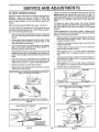
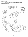
TO REMOVE
MOWER
(See Fig. 17)
Mower wilt be easier to remove from the right side of tractor.
°
Place attachment clutch in "DISENGAGED"
•
Move attachment lift lever forward to lower mower to its
lowest position.
•
Roll belt off engine pulley,
•
Disconnect clutch rod from clutch lever by removing
retainer spring,
•
Disconnect anti-sway bar from chassis bracket
removing retainer spring,
•
Disconnect suspension arms from rear deck brackets
by removing retainer springs,
•
Disconnect front links from deck by removing retainer
springs,
•
Raise lift lever to raise suspension arms, Slide mower
out from under tractor,
CLUTCH
position.
CLUTCH
SPRING
SUSPENSION
ARMS
by
MOWER
Raise attachment
ENGINE
PULLEY
SPRINGS
SIDES)
IMPORTANT:
IF AN ATTACHMENT OTHER THAN THE
MOWER IS TO BE MOUNTED TO THE TRACTOR, THE
R,H, AND LH. SUSPENSION ARMS MUST BE REMOVED
FROM TRACTOR.
TO INSTALL
LEVER
RETAINER
SPRING
(See Fig. 17)
ANTI-SWAY
lift lever to its highest position_
•
Slide mower under tractor with discharge guard to right
side of tractor,
•
•
Lower lift lever to its lowest position°
Install mower in reverse order of removal instructions,
BAR
RETAINER
SPRINGS
(BOTH SIDES)
FIG. 17
18
, ,
,111,,iii1,1.1i,iiii....
i ,111
,
,
i,
,,,i,,i,,
_
...... _:__:_=_
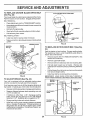
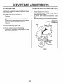
SERVICE AND ADJUSTMENTS
.... i,,,,i,,,,,,,,,i....
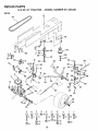
TO LEVEL
MOWER
i
....
i,,
, ,i,i, ,,,i
Adjust the mower while tractor is parked on level ground or
driveway.
Make sure tires are properly inflated (See
"PRODUCT SPECIFICATIONS" on page 3).. If tires are
over or under inflated, you will not properly adjust your
mower,
To obtain the best cutting results, the mower housing
should be adjusted so that the front is approximately 1/4" to
3/4" lower than the rear when the mower is in its highest
position,
(See Figs. 18 and 19)
You will need two (2) standard 2 x 4 short pieces of wood
to make the following adjustment, Similar blocks measuring 1-1/2" thick may also be used.
•
Raise mower with attachment lift control to allow two
(2) 1-1/2" thick blocks to be placed under rear edge of
mower°
o
°
•
Check adjustment on right side of tractor. Measure distance"D" directly in front and behind the mandrel at bottom
edge of mower housing as shown.
Place one block directly be hind the left mandrel. Place
the remaining block under the stamped ridge on the
right rear edge of mower deck.
Lower mower deck to its lowest height of cut position
(See "TO ADJUST MOWER CUTTING HEIGHT" in
Operation section of this manual).
On both sides of tractor, loosen, but do not remove, the
fasteners securing the adjustable pivot brackets to
frame. Both brackets must be loose enough to move
freely.
,
Pull down firmly on suspension arm to remove any
slack in pivot bracket and hold while tightening rear
fastener first to secure. Tighten remaining fastener,
°
o
Repeat procedure on other side of tractor..
Raise mower with attachment lift control and remove
blocks from under mower.
........
FRONT_TO_BACK ADJUSTMENT (See Figs. 20 and 2t)
IMPORTANT: DECK MUST BE LEVEL SIDE-TO-SIDE. IF
THE FOLLOWING FRONT-TO-BACK ADJUSTMENT IS
NECESSARY, BE SURE TO ADJUST BOTH FRONT LINKS
EQUALLY SO MOWER WILL STAY LEVEL SIDE-TOSIDE_
HOUSING
SIDE-TO*SIDE ADJUSTMENT
,i iii
=
Before making any necessary adjustments, check that
both front links are equal in length. Both links should
be approximately 10-3/8".
°
If links are not equal in length, adjust one link to same
length as other link.
To lower front of mower loosen nut "E" on both front
links an equal number of turns°
When distance "D" is 1/4" to 3/4" lower at front than
rear, tighten nuts "F" against trunnion on both front
links..
•
°
o
°
°
To raise front of mower, loosen nut"F" from trunnion on
both front links. Tighten nut "E" on both front links an
equal number of turns.
When distance "D" is 1/4" to 3/4" !ower at front than
rear, tighten nut"F" against trunnion on both front links.
Recheck side-to-side adjustment.
"
PLACE TWO (2) 1-1/2" THICK BLOCKS UNDER REAR EDGE OF
DECK (Use wood 2 x 4's or equiv.)
"'
°
MANDREL
,,<;J, L.j: L
}}
.
.
FIG, 20
DIRECTLY
BEHIND
MANDREL
BOTH FRONT LINKS MUST BE EQUAL IN LENGTH
La2"L
_
UNDER
STAMPED
RIDGE
MOWER
MUST BE IN LOWEST HEIGHT OF CUT POSITION
FIG. 18
ADJUSTABLE
PIVOT BRACKET
NUT "E"
FRONT LINKS
FIG. 19
19
TRUNNION
FIG. 21
=,
HH"=""="HH,H'
'
I= I= =' ='
SERVICE AND ADJUSTMENTS
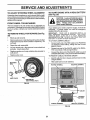
TO REPLACE
(See Fig. 22)
MOWER
BLADE
DRIVE BELT
WITH PARKING BRAKE "ENGAGED"
The mower blade drive belt may be replaced without tools.
Park the tractor on level surface° Engage parking brake,
BELT REMOVAL-
NUT "A"
,
•
Place attachment clutch in "DISENGAGED" position.
Move attachment lift lever forward to lower mower to its
lowest position.
•
Roll belt off engine pulley_
•
Work belt off both mandrel pulleys and idler pulleys°
NUT
•
Pull belt away from mower,
BELT INSTALLATION •
Install new belt in reverse order of removal.
•
Make sure belt is in all pulley grooves and inside all belt
guides.
ENGINE
MANDREL
PULLEY
ARM
FIG, 23
PULLEY
IDLER
PULLEYS
TO REPLACE
MOTION
DRIVE
BELT
(See Fig.
24)
Park the tractor on level surface, Engage parking brake.
For assistance, there is a belt installation guide decal on
bottom side of left footrest.
MANDREL
PULLEY
BRAKE
Remove mower (See "TO REMOVE MOWER" in this
section of this manual,)
•
Remove upper belt keeper.
•
•
Remove belt from stationary idler and clutching idler,
Pull belt slack toward rear of tractor. Remove belt
upwards from transaxle pulley by deflecting belt keepers.
,
Pull belt toward front of tractor and remove downwards
from around engine pulley
•
Install new belt by reversing above procedure,
IMPORTANT;
MAKE SURE UPPER BELT KEEPER IS
POSITIONED PROPERLY BETWEEN LOCATOR TABS.
FIG. 22
TO ADJUST
*
(See Fig. 23)
Your unit is equipped with an adjustable brake system
which is mounted on the right side of the transaxle.
PULLEY
*
Depress clutch/brake pedal and engage parking brake.
,
Measure distance between brake operating arm and
nut "A" on brake rod.
°
tf distance is other than 1-1/2", disengage parking
brake, loosen jam nut and turn nut A until distance
becomes 1-1/2". Retighten jam nut against nut "A".
,
Engage parking brake and recheck distance°
•
Road test unit for proper stopping distance as stated
above, Readjust if necessary. If stopping distance is
stitl greater than six (6) feet in highest gear, further
maintenance is necessary, Contact your nearest au,thorized service center,
TABS
CLUTCHING
IDLER
If unit requires more than six (6) feet stopping distance at
high speed in highest gear, then brake must be adjusted.
IPPER BELT
KEEPER
IDLER
20
FIG. 24
_L
II '11111'
ADJUSTMENTS
SERVICE
iii1,11,1
TO ADJUST
i , i1,,11111
......................
STEERING
TO START ENGINE
WHEEL ALIGNMENT
when wheels are positioned straight forward, remove steering wheel and reassemble per instructions in the Assembly
section of this manual.
WHEEL
CAUTION: Lead-acid batteries generate explosive gases. Keep sparks, flame
and smoking materials away from batteries.
Always wear eye protection
when around batteries.
TOE-IN/CAMBER
The front wheel toe-in and camber are not adjustable on
yourtractor, Ifdamage hasoccuredtoaffect the front wheet
toe-in or camber, contact your nearest authorized service
center.
TO REMOVE
WHEEL
FOR REPAIRS
i
i ,11iiii ,i
If your battery is too weak to start the engine, it should be
recharged° If "jumper cables" are used for emergency
starting, follow this procedure:
IMPORTANT:
YOUR UNIT IS EQUIPPED WITH A 12
VOLT NEGATIVE GROUNDED SYSTEM. THE OTHER
VEHICLE MUST ALSO BE A 12 VOLT NEGATIVE
GROUNDED SYSTEM. DO NOT USE YOUR TRACTOR
BATTERY TO START OTHER VEHICLES.
(See Fig.
25)
•
-
WITH A WEAK BA'N'ERY
(See Fig. 26)
If steeringwheel crossbarsare not horizontal(leftto right)
FRONT
,i
B_ock up axle securely.
Remove axle cover, retaining ring and washersto allow
wheel removal (rear wheel contains a square key - Do
not lose),
TO ATTACH JUMPER CABLES o
Connect each end of the RED cable to the POSITIVE
(+) terminal of each battery, taking care not to short
against chassis
Connect one end of the BLACK cable to the NEGATIVE (-) terminal of fully charged battery_
Connect the other end of the BLACK cable to a good
CHASSIS G ROUND, away from fuel tank and battery.
•
Repair tire and reassemble.
•
On rear wheels only: align grooves in rear wheel hub
and axle. Insert square key.
o
o
Replace washers and snap retaining ring securely in
axle groove.
•
o
Replace axle cover.
TO REMOVE CABLES, REVERSE ORDER •
WASHERS
o
RETAINING
RING
BLACK cable first from chassis and then from the fully
charged battery_
RED cable last from both batteries.
NEGATIVE TERMINAL
POSITIVE TERMINAL
\
!
AXLECOVER
SQUARE
KEY
(REARWHEELONLY)
FIG. 25
CHARGED
BATTERY
\
NEGATIVE TERMINAL
POSITIVE TERMINAL
FIG. 26
21
SERVICE AND ADJUSTMENTS
TO REPLACE
TO REMOVE HOOD AND GRILL (See Fig. 27)
FUSE
Replace with 30 amp automotive-type plug-in fuse. The
fuse holder is located in the engine compartment, directly
in front of the dash.
TO REPLACE HEADLIGHT
•
Raise hood.
•
Unsnap headlight wire connector,
•
Stand in front of tractor.
Grasp hood at sides, tilt
forward and lift off of tractor.
BULB
•
Raise hood.
•
To reinstall, slide hood pivot brackets into srots in
frame.
•
Pul! bulb holder out of the hole in the backside of the
gritL
•
Reconnect headlight wire connector and ctose hood,
•
Replace bulb in holder and push bulb holder securely
back into the hole in the backside of the grill+
Ctose hood_
,
HEADLIGHT
WIRE
CONNECTOR
HOOD
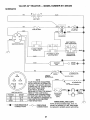
INTERLOCKS
AND RELAYS
Loose or damaged wiring may cause your tractor to run
poorly, stop running or prevent it from starting_
•
Check wiring. See electrical wiring diagram in Repair
Parts section of this manual.
FiG+ 27
22
u,,,ll .....................
, i,,,
u i....
SERVICE AND ADJUSTNI
i1,11 i1,,,
i,,i
ENGnNE
TO ADJUST THROTTLE
(See Fig= 28)
CONTROL
FINAL SETTING -
CABLE
•
The throttle control ;las been preset at the factory and
adjustment should not be necessary° Check adjustment as
described below before loosening cable. If adjustment is
necessary, proceed as follows:
Start engine and allow to warm for five minutes. Make
final adjustments with engine running and shift/motion
control lever in "NEUTRAL" position°
°
Move throttle control lever to "SLOW" position. With
finger rotate and hold throttle lever against idle speed
screw° Turn id e speed screw to attain 1750 RPM
-
With enginenot
running, move throttle control lever
from SLOW to CHOKE" position_ Slowly move lever
from "CHOKE" to "FAST" positiom
•
•
Check that holes"A" in governor control leverand hole
in governor plate line-up. If holes "A" are not aligned,
loosen clamp screw and movethrottle cable until holes
are aligned. Tighten clamp screw securely.
While still holding throttle lever against idle speed
screw, turn idle mixture valve in (clockwise) until engine begins to die and then turn out (counterclockwise)
until engine runs rough. Turn valve to a point midway
between those two positions° Release throttle lever.
ACCELERATION
GOVERNOR
CONTROL LEVER
GOVERNOR
CONTROL PLATE
•
TEST -
Move throttle control lever from "SLOW" to "FAST"
position. If engine hesitates or dies, turn idle mixture
valve out (counterclockwise) 1/8 turn. Repeat test and
continue to adjust, if necessary, until engine accelerates smoothly..
High speed stop is factory adjusted.
damage may result.
HOLES "A"
CLAMP
SCREW
IMPORTANT:
NEVER TAMPER WITH THE ENGINE
GOVERNOR, WHICH iS FACTORY SET FOR PROPER
ENGINE SPEED. OVERSPEEDING THE ENGINE ABOVE
THE FACTORY HiGH SPEED SETTING
CAN BE
DANGEROUS. tF YOU THINKTHE ENGINE-GOVERNED
HIGH SPEED NEEDS ADJUSTING, CONTACT YOUR
NEAREST AUTHORIZED SERVICE CENTER, WHICH HAS
PROPER EQUIPMENT AND EXPERIENCE TO MAKE ANY
NECESSARY ADJUSTMENTS°
THROTTLE
CABLE
THROTTLE
LEVER
FIG. 28
TO ADJUST
CARBURETOR
IDLE SPEED
SCREW
(See Fig. 29)
The carburetor has been preset at the factory and adjustment should not be necessary. However, minor adjustment may be required to compensate for differences in fuel,
temperature, altitude or load. Ifthe carburetor does need
adjustment, proceed as follows:
In general, turnig idle mixture valve in (clockwise) decreases the supply of fuel tothe engine giving a leaner fueV
air mixture. Turning the idle mixture valve out (counterclockwise) increases the supply of fuel to the engine giving
a richer fuel/air mixture°
IMPORTANT: DAMAGE TO THE NEEDLE VALVE AND
THE SEAT IN CARBURETOR MAY RESULT IF SCREW IS
TURNED IN TOO TIGHT
PRELIMINARY
SETTING -
•
Air cleaner assembly must be assembled tothe carburetor when making carburetor adjustments.
•
Be sure the throttle control cable is adjusted properly
(see above).
•
With engine off turn idle mixture valve !n (clockwise)
closing it finger tight and then turn out (counterclockwise) 1 full turn.
Do not adjust -
IDLE MIXTURE
VALVE
FIG. 29
23
ENGINE
Immediately prepare your tractor for storage at the end of
the season or if the tractor will not be used for 30 days or
more°
FUEL SYSTEM
IMPORTANT:
IT IS IMPORTANT TO PREVENT GUM
DEPOSITS FROM FORMING IN ESSENTIAL
FUEL
SYSTEM PARTS SUCH AS CARBURETOR, FUEL FILTER,
FUEL HOSE, OR TANK DURING STORAGE.
ALSO,
EXPERIENCE INDICATES THAT ALCOHOL BLENDED
FUELS (CALLED GASOHOL OR USING ETHANOL OR
METHANOL) CAN ATTRACT MOISTURE WHICH LEADS
TO SEPARATION AND FORMATION OF ACIDS DURING
STORAGE.
ACIDIC GAS CAN DAMAGE THE FUEL
SYSTEM OF AN ENGINE WHILE IN STORAGE_
gasoline in the tank inside a building
where
fumesNever
may store
reachthe
an tractor
open flame
CAUTION:
with
or spark. Allow the engine to cool
before storing in any enclosure.
1,1,,11 i1,1 i,i
,,, ,i
,
TRACTOR
Remove mower from tractor for winter storage. When
mower is to be stored for a period of time, clean it thoroughly, remove all dirt, grease, leaves, etco Store in a
clean, dry area.
•
Clean entire tractor (See"CLEANING" in the Customer
Responsibilities section of this manual).
°
Inspect and replace belts, if necessary (See belt replacement instructions in the Service and Adjustments
section of this manual)°
o
Lubricate as shown in the Customer Responsibilities
section of this manual.
o
Be sure that all nuts, bolts and screws are securely
fastened.. Inspect moving partsfordamage
breakage
and wear. Rep ace if necessary.
•
Touch up all rusted or chipped paint surfaces; sand
lightly before painting°
°
Drain the fuel tank°
°
Start the engine and let it run until the fuel lines and
carburetor are empty.
o
Never use engine or carburetor cteaner products inthe
fuel tank or permanent damage may occur.
Use fresh fuel next season_
°
NOTE:
Fuel stabilizer is an acceptable alternative in
minimizing the formation of fuel gum deposits during storage. Add stabilizer to gasoline in fuel tank or storage
containsr_ Always follow the mix ratio found on stabitizer
container. Run engine at least 10 minutes after adding
stabilizer to allow the stabilizer to reach the carburetor. Do
not drain the gas tank and carburetor if using fuel stabilizer.
ENGINE OIL
Drain oil (with engine warm) and replace with clean engine
oil {See "ENGINE" in the Customer Responsibilities
section of this manual)°
BATTERY
•
Fully charge the battery for storage.
°
After a .period of time in storage, battery may require
rechargmg_
•
Remove spark plug(s).
•
To help prevent corrosion and power leakage during
long periods of storage, battery cables should, be
disconnected and battery cleaned thoroughly (see q'O
CLEAN BATTERY AND TERMINALS
in the Customer Responsibilities section of this manual).
°
Pour one ounce of oil through spark plug hole(s) into
cylinder(s).
°
Turn ignition key to"START" position for a few seconds
to distribute oil,
After cleaning, leave cables disconnected and place
cables where they cannot come in contact with battery
terminals.
°
Replace with new spark plug(s).
o
Be sure battery drain tube is securely attached.
•
Do not store gasoline from one season to another.
•
If battery is removed from tractor for storage do not
store battery d recty on concrete or damp surfaces.
•
Replace your gasoline can if your can starts to rust.
Rust and/or dirt in your gasoline will cause problems.
-
If possible, store your tractor indoors and cover it to
give protection from dust and dirt.
•
CYLINDERS
OTHER
•. -.-Cover your tractor with a suitable protective cover that
does not retain moisture. Do not use plastic. Plastic
cannot breathe which allows condensation to form and
will cause your tractor to rust.
IMPORTANT: NEVER COVER TRACTOR WHILE ENGINE
AND EXHAUST AREAS ARE STILL WARM.
24
TROUBLESHOOTING
PROBLEM
CAUSE
Will not start
1,
2o
3,
4.
5.
6,
7,
8.
9.
10,
Hard to start
Out of fue!,
Engine not"CHOKED"
Engine flooded,
Bad spark plug,
Dirty air filter,.
Dirty fuel filter,
Water in fuel.
POINTS
CORRECTION
1.
2.
3.
4.
5.
6.
7.
properly°
Loose or damaged wiring.
Carburetor outof adjustment.
Engine valves out of adjustment
8,
9.
10,
Filt fuel tank,
See "TO START ENGINE" in Operation section°
Wail several minutesbefore attempring to start.
Replace spark plug,.
Clean/replaceair filter.
Replace fuel filter_
Drain fuel tank and carburetor, refill tank with fresh
gasolineand replace fuelfilter.
Check all wiring.
Contact Sears Service Center/Department.
Contact Sears Service Center/Department.
1.
2,
3.
4.
5,
6,
7,
8
Dirty air rilter.
Bad spark plug.
Weak or dead battery,
Dirtyfuelfilter.
Stale or dirty fuel,
Looseor damagedwiring,
Carburetor outof adjustment
Enginevalvesout of adjustment.
1o
2,
3,
4.
5,
6,
7,
8,
Cleanlreplace air rifler.
Replace spark plug,
Recharge or replace battery.
Replace fuel filter,
Drain fuel tank and refill with fresh gasoline,
Check all wiring.
Contact Sears Service Center/Department,
Contact Sears Service Center/Department,
t.
2.
3.
4,
5.
6
7,
8_
9,
Clutch/brake pedal not depressed.
Attachment clutchisengaged.
Weakordead battery.
Blown fuse,
Corroded battery terminals.
Loose or damaged wiring,
Faulty ignirion switch.
Faulty solenoidor starter,
Faulty operator presenceswitch(as).
1.
2.
3.
4_
5.
6.
7.
8.
9
Depress ctutctVbrakepedal.
Disengage attachment clutch.
Recharge or replace battery.
Replace fuse.
Clean battery terminals.
Check all wiring°
Chscldraplace ignition switch,
ChecWreplacesolenoidor starter_
Contact Sears ServiceCanter/Department.
Engine clicks but will not
start
1,
2_
3.
4_
Weak or dead battery,
Corroded battery terminals.
Looseor damaged wiring.
Faulty solenoid or starter°
1.
2,
3.
4_
Rechargeor replace battery.
Clean battery terminals.
Check all wiring
ChecWreplacesolenoidor starter,,
Loss of power
1.
2o
3.
4.
5.
6.
7,
8.
9r
Cutting too much grass/toofasL
Throttle in "CHOKE" position.
Build-up of grass, leaves and trash under mower.
Dirty air filter.
Low oil leve!ldirty oil.
Faally sparkplug.
Dirty fuel filter,
Stale or dirty fuel
Watarin fuel.
1o
2.
3.
4,
5.
6,
7.
8.
9.
Set in "Higher Cut"position/reduce speed.
Adjust throttlecontrol.
Clean undersideof mower housing.
Cleanlreptace alrfilter.
Check ell leveltchange oil.
CIean and regap or change sparkplug,
Replace fuelfilter,
Drain fuel tank and refill with fresh gasoline.
Drain fuel lank and carburetor,refill tank with fresh
gasoline and replacefuel filter,
Connect and tighten sparkplug wire.
Clean engine air screentfins.
Clean/replacemuffler. ...........
Checkall wiring.
Contact Sears Service Center/Department.
Contact Sears Service Center/Department.
i
Engine will not turn over
i
lO, Sparkplug wire Ioose.
11, Dirty engineair screen/fins
12. Dirty/cloggedmuffler.
....
13, Looseor damaged wiring.
14, Carburetor out of adjustment,
t5, Engine valves outof adjustment,
Excessive vibration
1o.
11,
12.
13.
14.
15o
1o Worn, bent or loose blade.
2. Bent blade mandrel.
3. Loose/damaged part(s),
25
1,
2.
Replace blade, Tighten blade bolt,
Replace blade mandrel,
3
Tighten loose pad(s).
Replace damaged
parts.
J
POINTS
TROUBLESHOOTING
CAUSE
PROBLEM
i
CORRECTION
, ii,,lUU
Engine continues to run
when operator leaves seat
with attachment clutch
t.
Faulty operator-safety presence centr!! system_
I.
Check wiling, switches and connections,
if not
corrected, contact Sears Service Center/Department.
to
2.
Worn, bent or looseblade,
Mower deck not level
3.
4.
Buildup of grass, leaves, and trash under mower,
Bent blade mandrel"
5o
Clogged mower deck vent holes from buildup of
grass, loaves, and trash around mandrels.
1_
2.
3,
4.
5.
Replaceblade, Tighten blade bolt.
Level mower deck.
Clean underside of mower housing.
Replace blade mandrel.
Clean around mandrels to open ventholes.
Mower blades wilt not
rotate
1,
Obstruction
I.
Remove obstruction.
2,
3.
4.
Wom/damaged mower drive belt,
Frozen idler pulley.
Frozen blade mandrel.
23.
4.
Replace mower drive belt,
Replace idler pulley.
Replace blade mandrel°
Poor grass discharge
1,
2.
3.
4,
5,
6.
7.
8.
9.
10,
11.
Engine speed too slow
Travel speed too fast,
Wet grass.
Mowerdecknot level.
Low/uneventire air pressure,
Wom, bent or looseblade.
Buildup of grass, leavesand trashunder mower.
Mower drive belt worn
Blades improperlyinstalled,
Improper bladesused.
Clogged mower deck vent holes from buildup of
grass, leaves, and trash around mandrals,
1.
2,
3.
4_
Place throtlIa control in =FAST" position,
Shift to slower speed.
Allow grass to dry before mowing.
Level mower deck.
engaged
Poor cut. uneven
, i iiiiiil,,u,,i
Headlight{s) not Working
(if so equipped)
.....................
ii,
in clutch mechanism.
1°
2.
3.
4,
5.
Switch is "OFF".
Bulb(s) bumedout
Faultylightswitch
Looseor damaged wiring,
Blownfuse_
1.
2.
3,
4.
Bad battery ceil(s).
Poor cable connections.
Faulty regulator (if so equipped),
Faulty aitemater.
1,
Engine throttle control not set at'SLOW'
position for 3o seconds before stopping engine.
5
6.
7.
8.
9.
I0_
1I.
Check tires for proper air pressure.
Replaoetsha_en
blade. Tighten blade bolt.
Clean underaide of mower housing.
Replace mower ddve belt,
ReinstaIf blades sharp edge down.
Replace with blades listed in this manual.
Clean around mandrels to open vent holes.
1_
2.
3_
4,
5,
Turn switch"ON".
Rap]ace bulb(s)_
Check/replace tight switch,
Check wiring and connections.
Replace fuse.
uul,l,,ul,,,
Battery will not charge
Engine "backfires"
when turning engine
"OFF"
2_
Replace battery
Check/clean all connections.
3
4.
Replace regulator.
Replace altemater
1.
Move throttlecontrolto 'SLOW' position and allow
toidle for 80 secondsbefore stoppingengine,
t
26
r
REPAIR PARTS
12.5 HP 42" TRACTOR
- - MODEL NUMBER
917.255430
ELECTRICAL
A
B
12
C
13
_'_14
D
18
E
0
F
35
32
33
37
_- - - 15
28
I
!
19
\
\
28
12.5 HP 42" TRACTOR - - MODEL NUMBER 917.255430
SCHEMATIC
BATTERY
| .....
I
RED
"
!
I
RED
RED
FUSE 30 AMP.
STARTER
WHITE
D
[ _
111
--
i
t
SOLENOID
BLACK
|
IGNITION SWITCH
F
I ....
l ....
I
I
i
t
I
l
CLUTCH 1 BRAKE
(PEDAL UP)
7
SEAT SWITCH
(NOT OCCUPIED)
I
I
I
....
_
_
_
I
! ....
I
I
I
7
,
,
ATT'MENT CLUTCH
(CLUTCH OFF)
BLACK
1
I
IBLACK
._
GROUNDING
CONNECTOR
o,T,o,
j s,ARK
BLACK
UNIT
PLUG
ALTERNATOR
3 AMPSOG
@ 8600 RPM
(gATTERY iN LINE)
NOTE
IGNITION SWITCH
POSITION
CIRCUIT
OFF
ON
START
M +G
B+L
B+ S
[
ORANGE
___
WITH A SPECIAL ALTERNATOR
SYSTEM. THE LIGHTS ARE NOT
CONNECTED TO THE BATTERY,
YOUR
TRACTOR
EQUIPPED
I,__
"X
BUT HAVE
THEIR IS
OWN
ELECTRICAL SOURCE.
BECAUSE OF THIS, THE BRIGHT- --_L_L'_,
NESS OF THE LIGHTS WILL
H__
CHANGE WITH ENGINE SPEED.
SWITCH
AT IDLE THE LIGHTS WILL DiM.
(OFF)
AS THE ENGINE IS SPEEDED UP,
THE LIGHTS WILL BECOME
THEIR BRIGHTEST.
NON-REMOVABLE
CONNECTIONS
20VOLTS AC (MtN°)
_
REMOVABLE
CONNECTIONS
27
,,...,A,_
_vPs
o 11VOLTS
AC@;3600
RPM,
ALTERNATOR
t H'EGADs
SI4E-A-DLI
'--_
WIRING INSULATED CLIPS
NOTE: If wiring insulated clips were removed for servicing of unit, they should
be replaced to properly secure your wiring.
/_
REPAIR PARTS
12.5 HP42" TRACTOR
- = MODEL NUMBER
917.255430
ELECTRICAL
KEY
NO.
PART
NO.
1
2
3
4
5
6
7
8
9
'tO
11
12
13
14
15
16
17
18
19
20
121265X
STD365402
124211X
132017
4207J
132202
4799J
129965
109596X
t09081X
STD551125
73350400
74780408
STD551225
STD541425
131563
109553X
STD601005
I04445X
STD60t005
DESCRIPTION
*
*
*
*
*
*
Battery 12 Volt 25 Amp
Switch I_n 5 Term Wo/wash/nut
Nut Ignition
Harness lgn Bs Dash Headlights
Cable Ground 6ga 12"black
Cable Battery 6 Ga 42"red
Cable Battery 6ga 11 "red
Case Battery Hinge Mechanical
Clamp Hose Olive
Solenoid
Washer Lock 1/4
Nut Jam Hex 1/4-20 Unc
Bolt Fin Hex 1/4-20uncx1/2 Gr5
Washer Lock Ext Tooth 1/4
Nut Keps Hex 1/4-20 Unc
Cover Terminal Red
Switch Intlk Clutch Red 4 Term
Screw Tap Hex #10-24unc X t/2
Switch intlk Clutch Red 2 Term
Screw Tap Hex #10-24unc X 1/2
KEY
NO.
PART
NOo
21
22
23
24
25
26
27
28
29
30
31
32
121305X
121264X
74760412
STD551025
STD551125
STD541025
I09310X
108824X
109238X
123620X
110712X
136849
33
34
35
36
37
38
7662J
108236X
STD601005
130890
STD601005
STD551225
NOTE:
29
DESCRIPTION
*
*
*
*
*
*
Switch Plunger Nc Gray
Caps Battery 25/30 Amp
Bolt Hex Hd 1/4-20unc X 3/4
Washer 9/32 X 5/8 X 16 Ga
Washer Lock Hvy Helical 1/4
Nut Fin Hex 1/4-20 Unc
Key Ign Molded Craftsman
Fuse 30 Amp Auto Green
Tube Plastic 12"
Cover Sw Key Blk I 25 Text Sit
Switch Light Blk BIk Red
Harness Socket Light
(Includes Key #33)
Bulb Light #1141
Bracket Switch Clutch
Screw Tap Hex #10-24unc X 1/2
Bracket Switch Interlock
Screw Tap Hex #10-24unc X 1/2
Washer Lock Internal Tooth 1/4
All component dimensions
1 inch = 25°4 mm
given in U.& inches,
REPAIR PARTS
12.5 HP 42" TRACTOR
CHASSIS
, - MODEL
NUMBER
917.255430
AND ENCLOSURES
A
B
C
D
E
F
G
I
K
g
i
D /
_
21
17
11
30
G
FJ
13
31
33
37
34
3O
REPAIR PARTS
12.5 HP 42" TRACTOR
CHASSIS
KEY
NO.
- - MODEL NUMBER
917,255430
AND ENCLOSURES
PART
NO,
1 135034
2 130805
3 17490612
6 130800X029
7 17490608
8 2751R
9 J37411X012
10 5479J
11 122795X
'12 121794X
13 124031X012
14 17490608
15 74180512
16 STD54143!
17 131445X417
18 126938X
19 STD512505
20 8TD551125
21 122933X
22 124479X
24 STD523707
KEY
NO.
DESCRIPTION
*
*
*
*
Chassis Weldment 12ga 38/42
Drawbar, 12 Ga
Screw Thdrol 3/8-16x3/4 Ty4t
Saddle Silkscreen 6sp English
Screw Thdrol 3/8-16xl/2 Tyott
Clip Line Fuel 13/32 Mtg Hole
Dash Silkscreened Sears Eng
Plug Button BIk 359 Dia
Panel Pnt Dash Lh
Cover Access Black Square
Panel Slkscr Dash Rh Weldment
Screw Thdrol 3/8-16xl/2 Ty4t
Screw Mach Trhd 5/16-18uncx3/4
Nut Keps 5/16-18 Unc
Hood Asm Pnt Weld Silver Powde
Bumper Hood
Bolt Fin Hex 1/4-20unc X 1/2
Washer Lock Hvy Helical 1/4
Rivet Ratchet Nylon
Washer Nylon BIk 28x 75x 19
Bolt Fin Hex 3/8-16uric X 3/4
PART
NO.
25
26
27
28
29
30
31
32
33
34
85
36
37
88
19131312
STD541437
17490608
123915X
124029X
109872X417
136619
17490612
105465X417
105464X417
STD533707
STD541437
105466X
'134774
39
134775
40
50
51
STD533707
STD541437
STD551025
NOTE;
31
DESCRIPTION
Washer 13/32 X 13/16 X 12 Ga
* Nut Crownlock 3/8-t6 Unc
Screw Thdrol 3/8-16xl/2 Ty.tt
Grille Grey
Lens Headlight Bar Clear
Fender Pnt
Bracket Pnt Fender
Screw Thdrol 3/8-16x3/4 Ty-tt
Footrest Pnt Lh Perf (silver)
Footrest Pnt Rh Perf (silver)
* Bolt Rdhd Sht Sqnk 3/8-16 X3/4
* Nut Crown!ock 3/8-t6 Unc
Pad Footrest Rbr Sq Craftsman
Bracket, Asm Pivot, L.H., Mower
Rear
Bracket, Asm Pivot, R.H, Mower
Rear
Bolt, Carriage 3/8-16 x 3/4
Locknut Hex W/Washer 3/8q6
Washer 13/32 x 3/4 x I6 Ga
All component dimensions
1 inch = 25.4 mm
given in US. inches.
REPAIR PARTS
12.5 HP 42" TRACTOR
- - MODEL NUMBER
917,255430
DRIVE
D
62
A
B
5
C
6
D
E
71
(_)
72
_
32
F
G
H
18
1
67
19 _
60 _
68
I
0
j
2
_
$3
61
REPAIR PARTS
12,5 HP 42" TRACTOR
- - MODEL NUMBER
917.255430
DRIVE
KEY
NO.
PART
NO.
137363
2
3
4
5
6
7
8
9
10
11
12
13
14
15
16
17
18
19
20
21
22
23
24
25
26
27
28
29
3O
31
32
33
34
35
36
37
38
39
40
110422X
123666X
12000028
121520X
17490512
130802
131679
19151216
STD561210
105701X
19O91210
71040412
STD551125
STD523727
STD541437
121520X
STD523707
STD541437
17490512
106933X
130804
STD541437
STD541237
106888X
STD551037
STD561210
128904
124236X
1308O7
127275X
STD523707
STD541437
122424X
120183X
STD551062
STD571810
123674X
STD523727
4470J
DESCRIPTION
Transaxle 6sp Std Dana,
Model No, 4360-48
Spring Return Brake T/a Zinc
Pulley Transaxle Alum
Ring Retainer # 5100-62
Strap Pnt Torque 30 Deg Bik
Screw Thdrol 5/16-18 X 3/4 Tyt
Plate Pnt Rod Shift T/a (blk)
Rod Shifter Blk (dana)
Washer 15/32 X 3/4 X 16ga
* Pin Cotter 1/8 X 1 Cad
Washer Plate Shf 388 Sq Hole
Washer 9/32 X 3/4 X 10 Ga
Bolt Fin Hex 1/4-28unfx3/4 Gr8
* Washer Lock Hvy Helical 1/4
* Bolt Fin Hex 3/8-16unc X 2-3/4
* Nut Crowniock 3/8-16 Unc
Strap Pnt Torque 30 Deg Bik
* Bolt Fin Hex 3/8-16unc X 3/4
* Nut Crown!ock 3/8-16 Unc
Screw Thdrol 5/16-18 X 3/4 Tyt
Knob Rd 1/2-13 Plstc Thds Blk
Rod Brake Lt
* Nut Lock Hex W/wsh 3/8-16unc
* Nut Hex Jam 3/8-16 Unc
Spring Rod Brake 2 O0 Zinc
* Washer 13/32 X 13/16 X 16 Ga
* Pin Cotter 1/8 X 3/4 Cad
Rod Brake Parking Lt
Cap Parking Brake Red
Bracket Transmission
Keeper Belt Lh Lt 14 Ga
* Bolt Fin Hex 3/8-16unc X 3/4
* Nut Crownlock 3/8-16 Unc
Shaft Asm Pedal Foot 1 930
Bearing Nylon BIk 629 ld
*Washer 21/32 X 1 X 16 Ga
* Pin Roll 3/16 X 1"
Pulley Idler Flat
* Bolt Fin Hex 3/8-t6unc X 2-3/4
Spacer Split 395 X 59 Bzp
KEY
NO.
PART
NO,
41
42
43
44
45
46
47
48
49
50
51
52
53
54
55
56
57
58
59
60
61
62
63
64
65
66
67
68
69
70
71
72
73
74
75
76
77
78
109070X
19131312
STD541437
105706X
110812X
12000039
127783
123789X
123205X
STD523715
STD541437
STD551037
105710X
STD561210
105709X
STD561210
130801
127274X
136715
19131312
17490612
8883R
134825
7117O764
STD551143
129921
STD523710
19131312
STD541437
134683
STD523710
19132012
STD541437
109502X
121749X
STD581075
123583X
121748X
NOTE:
33
DESCRIPTION
Keeper Belt Retainer
Washer 13/32 X 13/16 X 12 Ga
* Nut Crownlock 3/8-16 Uric
Bearing Nyl 503 X 628 X 1 25
Washer Hardened
Ring Klip #t5304-50
Pulley Idler V Groove Plastic
Belicrank Asm
Retainer Belt Style Spring
* Bolt Hex Hd 3/8-16unc X 1-1/2
* Nut Crowniock 3/8-16 Unc
*Washer 13/32 X 13/16 X 16 Ga
Link Ctutch 7 66
* Pin Cotter 1/8 X 3/4 Cad
Spring Return Clutch 6 75 _
* Pin Cotter 1/8 X 3/4 Cad
V-belt Ground Drive 95 25
Keeper BeFt Rh Lt Pnt/zinc 16g
Retainer Belt Chassis Lh Zinc
Washer 13/32 X 13/16 X 12 Ga
Screw Thdrol 3/8q 6x3/4 Ty4t
Cover Pedal Btk Std
Pulley Engine
Boit Finhex 7/16-20 x 4 g5
* Washer Lock Hvy Hlcl Spr 7/t 6
Keeper Belt Engine Lh Lt
* Bolt Fin Hex 3/8-16unc X 1
Washer 13/32 X 13/16 X 12 Ga
* Nut Crownlock 3/8-16 Unc
Guide Belt Dr Mower Rh
* Bolt Fin Hex 3/8-16unc X 1
Washer 13/32 X 1-1/4 X 12 Ga
* Nut Crowntock 3/8-16 Unc
Spacer Split .80xl.94
Washer 25/32 X 1 1/4 X 16 Ga
* Ring E #5133-75
Key Square 2 0 X 1845/1865
Washer 25/32 X 1 5/8 X 16ga
All component dimensions
l inch = 25.4 mm
given in US
inches,
REPAIR PARTS
12.5 HP 42" TRACTOR
STEERING
- - MODEL NUMBER
917.255430
ASSEMBLY
38
39
46
/
36
1314 i
47
37
17
26
2k
10
/,<
,
44
35
23
30
31
24
29
25
26
34
43
43
REPAIR PARTS
12.5 HP 42" TRACTOR
STEERING
KEY
NO.
1
2
3
4
5
6
7
8
9
10
11
12
13
14
15
16
17
18
19
20
2!
22
23
- - MODEL NUMBER
917.255430
ASSEMBLY
PART
NO.
133741
133988
135227
t35228
6266H
121748X
19272016
12000029
3366R
130468
STD551t37
73610600
110438X
74011056
73901000
132624
132614
57079
124035X
126684X
STD551125
71070410
127501
KEY
NO.
DESCRIPTION
Wheel Steering Std Black
Axle Asm Front
Spindle Asm Lh
Spindle Asm Rh
Bearing RaceThrust Harden
Washer25/32 X 1 5/8 X 16ga
Washer 27/32 X 1 1/4 X 16 Ga
Ring Klip#t5304-75
Bearing Col Strg BIk
Link Drag Sol Ball Jt 20 064
* Washer Lock Hvy Hlcl Spr 3/8
Nut Fin Hex3/8-24Unf
Spacer Bearing Axle Front
Bolt Hex 5/8-11 Uric X 3-1/2
Locknut Flange 5/8-11 Unc
Pin Axle 5/8 X 1 55/1 54 Lg
Shaft Asm Strg 5/8 X 15 19 Lt
Washer Thrust 515x 750x 033
SupportShaft
Washer Shim 1/4 X 5/8 X 062
* Washer Lock Hvy Helicat !/4
Screw Hex Socket 1/4-20 X 5/8
ShaftAsm Pittman
24
25
-26
.27
-28
29
30
3!
32
33
34
35
36
37
38
39
40
41
42
43
44
45
46
47
PART
NO.
109816X
124036X
12000029
136874
6266H
17490612
STD551t37
73610600
130465
!26847X
19131416
STD561210
132196
STD6t1005
133742
19133808
STD541537
I04820X
124417X
121749X
121748X
12000029
121232X
6855M
NOTE:
35
DESCRIPTION
Nyfiner Snap In
Bracket Steering
Ring Klip #t5304-75
Gear Sector
BearingRace Thrust Harden
. ScrewThdrol 3/8-16x3/4 Ty-tt
Washer Lock Hvy Hlcl Spr 3/8
Nut Fin Hex 3/8-24 Unf
Rod Tie Wire Form 19 75 Mech
Bushing Rod Tie BIk Lt
Washer 13/32 X 7/8 X 16ga
* Pin Cotter 1/8 X 3/4 Cad
Bushing Strg 5/8 Id Dash
* Screw Slflp #10-16 X 1/2 Ty-b
Insert Cap Strg Wheet Std BIk
Washer 13/32 X 2-3/8 X 8 Ga
"Nut Lock Center 3/8-24unf
Adaptor Wheel Strg 640/635id
Boot Shaft Steering
Washer 25/32 X 1 1/4 X t6 Ga
Washer 25/32 X 1 5/8 X 16ga
Ring Klip #t5304-75
Cap Spindle Fr Top BIk
Fitting Grease
All component dimensions
1 inch = 25,4 mm
given in U..S. inches.
REPAIR PARTS
12.5 HP 42" TRACTOR
- - MODEL NUMBER
917.255430
SEAT ASSEMBLY
10
11
<.. ,/,..b
I
""S.',.
I
2..-
""
""
" >!"'""
\
I
"/
j
!
/
I
15
A
B
C
D
E
13
KEY
NO,
PART
NO,
1
127437
126656X
STD523707
19131210
2751R
STD541437
124181X
17490616
19131614
131451
121251X
121246X
121248X
72050411
t21249X
3
4
5
6
7
8
9
10
11
12
13
14
15
DESCRIPTION
Seat V350 Blk!red Craftsman
Bracket Pnt Pivot Seat (btk)
* Bolt Fin Hex 3t8:16(Jrlc X 914
Washer 13/32 X 3/4 X 10 Ga
Clip Line Fuel 13/32 Mtg Hole
* Nut Crownlock 3/8-16 Unc
Spring Seat Cprsn 2 250 Blk Zi
Screw Thdrol 318-16 X 1 Ty-tt
Washer t3/32 X 1 X 14 Ga
Pan Pnt Seat (blk)
Strip Foam Gray Or Black
Bracket Pnt Mounting Switch
BushingSnap Blk Nyl 50 td
Bolt Rdhd Sht Nk 1/4-20xl-3/8
Spacer Split 28 X 88 Zinc
KEY
NO.
PART
NO.
16
17
18
19
20
2t
22
23
24
25
26
121250X
123976X
STD511005
73951000
4171R
105529X
STD54143l
74780814
19171912
t27018X
STD551150
NOTE:
36
DESCRIPTION
Spring Cprsn t 27 BIR Pnt
Nut Lock 114 Lge Fig Gr5 Zinc
* Screw Sltd Pan Hd _10-32 X 1/2
Nut Keps #10-32 Unf
Clip Insulated 11/32 Mtg Hole
Bolt Shoulder 5/16-18 Unc Blkz
* Nut Crown Lock 5/16-18
Bott Fin Hex 1/2-13 X 7/8 Gr 5
Washer 17/32 X 1-3/16 X 12 Ga
Bolt Shoulder 5/16-18 X 62
* Washer Lock Hvy Hlcl Spr 1/2
All component dimensions
1 inch = 25.4 mm
given in US
inches
REPAIR PARTS
12.5 HP 42" TRACTOR
- - MODEL NUMBER
917.255430
DECALS
14 19
6
3
7 8
21
5
8
7
4
14
11
9
16
12
13
5
KEY
NO,
1
2
3
4
5
6
7
8
9
11
_
PART
NO.
136794
127908
124489X
124490X
132674
133644
13633t
108631X
125880X
133796
WHEELS
,,
KEY
NO.
DESCRIPTION
Decallnstruction Operat Eng
Decal Eng 12 5hp Ic Gold Craft
Decal Hood Slope Rh Craftsman
Decal Hood Slope Lh Craftsman
Decal Grille Lt4000 Craft Usa
Decal Maint Customer Sears Dom
Decal Pane! Side I/c Gold/blk
Decalli(die Cut)
Decal Fender Craftsman Red
Decal Caution English
12
t3
14
15
16
18
19
21
---
PART
NO.
4900J
109199X
131473
136832
12t343X
133179
132267
131265
1383!1
137633
DESCRIPTION
Deca! Clutch/brake English
Decal V-belt Dr Sch Tractor E
Decal Chassis 6 Sp 42"
Decal Mower Drive Schematic 42
Deca! Danger English
Decal Mower Qc System
Decai Insr Wh Strg Crafts Usa
Decal Lightbox
Decal Lift Handle
Manual, Owner's (English)
& TIRES
,10
KEY
NO.
PART
NO.
1
2
3
4
5
6
7
8
9
10
11
59192
65139
106222X
59904
106732X361
278H
9040H
106108X361
124635X
7t52J
t04757X
NOTE:
37
DESCRIPTION
Cap Value Tire
-Stem Value ....
Tire F Ts 15 X 6 0 - 6 Service
Tube Inner Front #35060
Rim Asm 6"front Silver Service
Fitting Grease
Bearing Flange
Rim Asm 8"rear Silver Service
Tire R Ts t8x8 5-8 Service
Tube Rear 9 5 X 8 Service
Cap Axle BIk 1 50 X 1 00
All component dimensions given in U.S_ inches.,
1 inch = 25_4 mm
REPAIR PARTS
12.5 HP 42" TRACTOR
- - MODEL NUMBER
917.255430
ENGINE
1
27
25
3O
14
36
F
32
\
33
./
37
38
29
23
/
I
OPTIONAL
EQUIPM
..........................
Spark A!reste! '
B
D
E
F
G
ENT
H
I
22
18
2O
19
38
21
REPAIR PARTS
12.5 HP 42" TRACTOR
- - MODEL NUMBER
917.255430
ENGINE
KEY
NO,
1
2
3
4
11
12
13
14
15
I6
17
18
t9
20
21
22
PART
NO.
132759
17720410
137418
137348
STD551131
71070510
125593X
13280324
13200300
STD551237
17490620
105736X
105839X
105838X
STD551025
123650X
23 128953
KEY
PART
NO.
NO.
DESCRIPTION
Control Throt Rh Blk Pd115 10
Screw Hex Thd Cut 1/4-20x5/8 T
Engine B&s t2.5hp I/c Dual 1 Vt,
Model No. 286707,
Type No. 0441-01
Muffler Exhaust B&s Lt
* Washer Lock Hvy Hlcl Spr 5/I6
Screw Hexhd Cap 5/16-18x5/8
Gasket 1 313 Id Tin Plated
Nipple Pipe 3/8 Npt X 3"
Elbow Std 90 Degree 3/8-18 Npt
* Washer Lock Ext Tooth 3/8
ScrewThdrof3/8-16x1-1/4Tytt
Shield Pnt Heat
Receptacle I/4 Turn Dacrotized
Retainer 1/4 Turn 365odx 222id
*Washer9/32X5/8X16Ga
Stud 1/4Turn (replaces 105751
24
25
26
27
29
30
31
32
33
34
35
36
37
38
STD601005
124027X
17030808
105037X
137180
127057X
109202X
123549X
123487X
124028X
17490412
19091416
101335K
- --
NOTE:
39
Shield Pnt Heat Browning Grass
DESCRIPTION
* Screw Tap Hex #10-24unc X 1/2
Shield Pnt Heat Hood Lt
Screw Spiderloc Hexhd#Sxl/2 Ab
Strip Foam 18"
Arrestor Spark
Strap Hood
Tank Fuel 1 25 Fr
Cap Asm Fuel W/sym Vented
Clamp Hose Blk
Bushing Snap Nyt Blk Fuel Line
Screw Hexwsh Thdrol 1/4-20x3/4
Washer 9/32 X 7/8 X 16ga
Line Fuel 9 50"
Plug Oil Drain (Order From Engine
Manufacturer)
All component dimensions
1 inch = 254 mm
given in U.S inches.
REPAIR PARTS
12.5 HP 42" TRACTOR
- - MODEL
NUMBER
917.255430
LIFT
7
8
I
11
/
4 5
it
!
6
6
13
13
161718
13
15
4O
13
REPAIR PARTS
12.5 HP 42" TRACTOR
- - MODEL NUMBER
917.255430
LIFT
KEY
NO.
1
2
3
4
5
6
7
8
t0
11
I2
t3
14
15
16
t7
18
t9
PART
NO,
136973
I22507X
105767X
12000002
19211416
120183X
125631X
122365)(
1225t2X
134619
135388
4939M
135563
127218
73350800
130171
73800800
130832
DESCRIPTION
Rod Asmo Lever
Shaft Asm. Lift
Pin Groove
E Ring #5t33-62
Washer 21/32 x 7/8 x 16 Ga,
Bearing Nylong
Grip Handle Fluted
Button Plunger Read
Spring Cprsn
Link Lift Lh Fixed Length
Link Lift Rh Fixed Length
Retainer Spring
Pin RolJ Sit 5/16 x 1_25
Link Front
Nut Jam Hex 1/2-13 Uric
Trunnion Bik Zinc
Nut Lock W/Wsh 1/2-13 Unc
Arm Suspension Rear
4'1
REPAIR PARTS
12.5 HP 42" LAWN TRACTOR
42" MOWER
- - MODEL
NUMBER
917.255430
DECK
38
36
33
32
31
30
21
22
24
17
16
28
29
18
t3-_
18
42
27
REPAIR PARTS
12.5 HP 42" LAWN TRACTOR
42" MOWER
KEY
NO.
PART
NO,
1
2
3
4
5
6
7
8
9
10
137525
72140506
138017
138018
124670X
130832
73800500
850857
10030600
129962
11
12
13
127843
129895
1_3_t=7-2.
14
15
16
17
t8
19
20
21
22
23
24
25
26
27
28
29
30
31
32
33
34
35
128774
t10485X
128961
72110618
73800500
73350800
136888
73680500
134753
131267
105304X
123713X
110452X
130968
19111016
131491
78158
129963
129861
73050900
72110614
133835
- - MODEL NUMBER
917,255430
DECK
KEY
NO,
DESCRIPTION
DECKAsm Mower42"
BOLT Rdhd Sqnk 5/16-18 Uncx3!4
BRACKETAsm.
Fr, Sway Bar
BRACKETAsmo Deck Sway Bar
RETAINER Spring
ARM Rear Suspension
LOCKNUT Hex W/Ins. 5/16-18 Unc
BOLT 3/8-24 x '125 Gr8 Patched
WASHER Lock Hvy 3/8 Unplated
WASHER Hard BladeMower
Vented
BLADE Mower High Perf 42"
BEARING Ball #6204 (mandrel)
SHAFT Asm W/lower Bearing (lnco
Key #6)
HOUSING Mandrel Vented (machd)
BEARING Ball Mandrel
STRIPPER Mower Vented
BOLT Rdhd Sqnk 3/8-16 x 2-t/4
BOLT, Carriage 5/t6-18x5/8
LOCKNUT HexW/lns_ 5/16-18
BAFFLE Vortex
NUTCrown Lock 5/16-18
STIFFENER Bracket 42" deck
BRACKET Deflector Mower 42"
CAP Sleeve 80 x 112 BIk Mower
SPRING Torsion Deflector 2 52
NUT Push Phos & Oil
SHIELD Deflector Mower 42" Blk
WASHER 11/32x5/8x16Ga
ROD Hinge 426 75Wig
BOLT 5/16-18 x t 25 T/t
WASHER Spacer Mower Vented
PULLEY Mandret 42"
NUT 9/'16 top Lock Flng Oil Dip
BOLT Rdhd 3/8-16 Unc x 1-3t4 Gr5
FASTNER Christmas Tree
PART
NO.
36
37
38
39
40
4t
42
43
44
45
46
131494
19131612
133502
133503
73680600
13355t
76020312
133504
134236
4497H
t7720410
47
48
49
131335
133944
133940
50
51
52
53
54
55
56
57
58
59
60
61
62
63
64
65
66
67
68
131340
69180
105529X
131845
133943
133844
122052X
127498
128759
133573
133550
131870
127847
121748X
12000029
128903
127845
106932X
130969
130794
136322
NOTE:
43
DESCRIPTION
PULLEY Idler Flat 3 060
WASHER 13/32 x 1 x 12 Ga
SPACER Arm Idler Upper Hdn 42"
STIFFENER Arm Idler Upper 42"
NUT Crownlock 3/8-16 Uric
ROD Pivot W/nibs
PIN Cotter 3/32 x 3/4 Cad
ROD Clutch Secondary Wlnibs
GUARD Mandrel Lh Black
SPRING Retainer 1 Zinc/cad
SCREW Hex Thd Cut
1/4-20 x 5/8 T
SPRING Extension
WASHER Hardened Smaller
ROLLER Asm Cam Follower 42"
deck
BOLT Shldr 10-24 Zinc Gr5 42"
NUT Lock #t0-24 Unc
BOLT Shoulder 5/t6-18 Uric Blkz
ARM Asm Pad Brake
WASHER Hardened
ARM Idler 42" mower Lt/yt
SPACER Retainer Pm Mower
BUSHING 747 Od x 794 Lg Brass
SPRING Clutch Mower 2 750 Zinc
ARM Asm Clutch Primary
ROD Clutch Primary W/nibs
SPRING Return
ARM Clutch Secondary
WASHER 25/32 x t-578 x 16 Ga
RING Klip #t5304-75
__ ..-_
BOLT Shoulder 3/8-16 Unc 1 44_,'_KEEPER Spring 4000
_.. \
KNOB Rd 3/8-16 Plstc Tflds Blk
V-BELT Mower 42" 92 40
MANDREL Asm Service (Includes
Key Noso 8-10, 12-t5, 31 and 33)
DECK Serv 42" Mech Vent
All component dimensions
t inch = 25.4 mm
given in US. inches
REPAIR PARTS
12.5 HP 42" TRACTOR
- MODEL NUMBER
917.255430
DANA TRANSAXLE
- MODEL NUMBER
4360-48
22
19
11 =
20
24
21
37
19
52
4O
53
41
54
44
45
5556
46
47
48
57
49
59
50
56
!119
55
6O
43*52
44
REPAIR PARTS
KEY PART
NO. NO.
1
2
138248
2274J
3
4
5
6
7
8
9
10
11
12
13
14
15
16
17
18
19
20
21
22
23
24
25
26
27
28
29
30
31
32
33
34
35
36
37
38
134400
105904X
105905X
138235
134399
134791
138241
2267J
134793
138240
120415X
2257J
138234
110078X
105909X
105910X
105911X
138242
138246
138236
73810500
138243
2244J
105916X
120470X
110070X
108977X
109254X
120405X
108980X
I20406X
134796
105925X
2232J
108978X
110079X
39
4O
124639X
120472X
12.5 HP 42" TRACTOR
- MODEL NUMBER
917.255430
DANA TRANSAXLE
- MODEL NUMBER
4360-48
KEY PART
NO. NO,
DESCRIPTION
Housing, Upper
Screw, Self-Tapping, Large
1/4-20x.734
Ball, Detent
Spring, Detent
Screw, Set
Kit, Shifter Assembly
Boot, Shifter
Screw, Tappingw/Sealer
Square Ring
Ring, Retaining
*Assembly, Kit, Shim .625 Shaft
Bearing, Flange
Washer, Plain °632 x 138 x .046
Key, Woodruff, #9
Assembly, Kit, Idput Shaft
Pinion, Bevel, 14Teeth
Ring, Retaining
Chain, 24 Pitches
Bearing, Ftange
Gear, Spur, 14 Teeth
Collar, Clutch
Assembly, Kit, Clutch Keys
Locknut 5/16-24
Shaft, Intermediate
Key, Woodruff, #61
Ring, Retainir]g
Sprocket, 18 Teeth
Spacer
Gear, Spur, 37 Teeth
Gear, Spur, 35 Teeth
Gear, Spur, 30 Teeth
Gear, Spur, 25 Teeth
Gear, Spur, 22 Teeth
Gear, Spur, 19 Teeth
Washer, Plain .640 x 1.37 x .061
Washer, Plain °632 x 1.00 x .026
Spacer .630 x 1 _00 x J69
Assembly, Gear, Combination of
12 Teeth and 35 Teeth
Shaft, idter
Spacer 635 x .875 x .755
41
42
43
44
45
46
47
48
49
50
51
52
53
54
55
56
57
58
59
60
61
62
63
64
65
66
67
105928X
110084X
134394
t20473X
105933X
t06151X
t20407X
I06589X
120408X
105937X
2226J
134401
2264J
120474X
110081X
105941X
110071X
t20952X
110082X
120475X
138247
t20961X
7294J
108989X
I20953X
I20954X
134799
68
69
70
71
138244
108996X
120956X
106596X
72
73
120416X
*
**
DESCRIPTION
Sprocket, 9 Teeth
Gear, Bevel, 42 Teeth
*Assembly, Kit, Shim .750 Shaft
Shaft, Drive
Gear, S 3ur, 12 Teeth
Gear, S 3ur, 15 Teeth
Gear, S 3ur, 20 Teeth
Gear, S 3ur, 25 Teeth
Gear, S 3ur, 28 Teeth
Gear, S 3ur, 31 Teeth
Washer Plain .632 x 1.00 x .060
Washer Neoprene
Washer Plain .758 x 1o25 x .031
Axle, L,H.
Gear, Miter, 15 Teeth
Ring, Retaining
Gear, Spur, 32 Teeth
Shaft, Cross
Gear, Miter, t5 Teeth
Axle, R,H.
Housing, Lower
Puck, Friction
Disc, Brake
Spacer
Jaw, Brake
Pin, Dowe!
Screw, Self-Tapping, Large
5/t6-18 x 2.25
Lever, Actuating
Washer, Plain .321 x 1o00 x .055
Bracket, Anti-Rotation
Screw, Self-Tapping, Large
5/t6-18 x !.44
Puck, Friction
Grease
Use in combinations
to maintain proper clearances
Order Key No. 15
NOTE: All component dimensions given in U.S, inches
1 inch = 25.4 mm
45
REPAIR PARTS
12.5 HP 42" TRACTOR
BRIGGS
& STRATTON
ENGINE
- MODEL
- - MODEL NUMBER
NUMBER
286707,
917.255430
TYPE NUMBER
0441-01
334
2_
307
Q
!
;92
757
615(9
614
(
_
(023o
523
_337
13
46
422
*SPECIAL
TOOLS REQUIRED
TO INSTALL.
46
358 GASKET
SET
REPAIR PARTS
12.5 HP 42" TRACTOR
BRIGGS
!121
& STRATTON
ENGINE
- MODEL
- - MODEL
NUMBER
NUMBER
286707,
917.255430
TYPE NUMBER
0441-01
CARBURET_B
,,OqERHAU
L"Kff'l
535
171
52
224
164
_
445
123
137
663
646_
• "r--'-
.__
........
j,
@
,
G..J _e284
138
i i,,
47
'N?
REPAIR PARTS
12.5 HP 42" TRACTOR
BRIGGS
1
& STRATrON
ENGINE
- MODEL
- - MODEL
NUMBER
NUMBER
286707,
TYPE
917.255430
NUMBER
0441-01
=H
tO
_
Housing Length --_
802
80t
NOTE:
To ldentlfy Brlggs end Stratton manufactured
starter motors, measure the housing length,
KEY NUMBER
MANUFACTURER
Brtggs &
Stratton
12V
Housing
Length
3-21/32"
309
310
311
510
544
Motor and
Thru Bolt
Brush
Drive
Armature
Drive Assy, Assembly
394805
94003
Assembly Assembly
395538
Assembly
390837
394856
490421 _
#398003
#280104
#490467
#94288
Clutch Assembly
Gear
Retainer and Pin
Roll Pin
(Key
(Key
(Key
(Key
Number
Number
Number
Number
513)
783)
876)
896)
665
1044
7s
4_2
48
802
Drive End Cap End Cap Assy,
Assembly
*Includes Brush Set
**Includes
801
Commutator
-
395537 _
8O3
Housing
Assembly
- 398159
REPAIR PARTS
12,5 HP 42" TRACTOR
BRIGGS
& STRATrON
KEY PART
NO. NO.
1
2
490450
399265
3
5
7
8
9
10
11
12
391086
494240
271866
391406
27803
94621
280100
271916
271997
271996
94622
94239
495162
94196
494238
291675
94624
492326
13
15
'16
18
20
22
23
24
25
26
27
28
29
31
32
33
34
35
36
37
40
41
42
222698
394661
394662
394663
394664
391780
392331
391781
391782
391783
260924
299691
391286
490348
490469
222299
92909
262246
262247
65906
26828
224502
221596
292260
93630
ENGINE
- MODEL
- - MODEL NUMBER
NUMBER
286707,
KEY PART
NO. NO.
DESCRIPTION
Cytinder Assembly
Bearing, Cylinder (Requires Special
Tools For Installation)
* Seal, Oil
Head, Cylinder
* Gasket, Cylinder Head
Breather Assembly
Gasket, ValveCover
Screw, Seres
Tube, Breather
* Gasket, Crankcase Cover 1/64"
* Gasket, Crankcase Cover °005"
* Gasket, Crankcase Cover .009"
Screw, Cylinder Head 3"
Plug, Oil Drain
Crankshaft
Key, Timing Gear
Base, Engine
*Seal, Oii
Screw, Seres, Base Mounting
Flywheel and Ring Gear Assembly,
Magneto
Key, Ffywheef
Piston Assembly, Standard
Piston Assembly +010" Oversize
Piston Assembly .020" Oversize
Piston Assembly .030" Oversize
Ring Set, Piston, Standard
Ring Set, Piston, Chrome, Standard
Ring Set, Piston .010" Oversize
Ring Set, Piston .020" Oversize
Ring Set, Piston .030" Oversize
Lock, Piston Pin
Pin Assembly, Piston, Standard
Pin Assembly, Piston .005" Over
Rod Assembly, Connecting
Rod Assembly, Connecting
.020" Undersize Crankpin Bore
Lock, Connecting Rod Screw
Screw, Connecting Rod
Valve, Exhaust
Valve, Intake
Spring, Intake Valve
Spring, Exhaust Valve
Guard, Flywheel
Retainer, Intake Valve
Rotocoil, Exhaust Valve
Retainer, Exhaust Valve Rotocoil
45
46
5t
262248
212897
272465
52
272554
63
75
78
95
98
104
105
106
t08
118
!21
94637
224061
93805
94098
495800
231789
231855
231854
224540
494383
495799
123
125
127
130
131
133
137
138
141
142
94616
495706
....
224539
494379
494381
281165
281164
494380
494537
494499
147
164
171
187
188
201
209
216
219
231794
213819
281051
393815
93535
262767
260871
262766
490815
917.255430
TYPE NUMBER
0441-01
DESCRIPTION
Tappet-Valve
Gear, Cam
*** Gasket, Carburetor
(Carburetor to Elbow)
* Gasket, Carburetor
(Elbow to Cylinder)
Stud, Carburetor Mounting
Washer, Spring
Screw, Seres
** Screw, Throttle
Screw, Idie Speed
** Pin, Float Hinge
** Valve Assembly, inlet Needle
Inlet Valve Seat
Valve, Choke
**Valve, Needle
Carburetor Overhaul Kit
(includes Items marked ** and _*)
Screw, Elbow Mounting
Carburetor Assembly
** Plug, Welch (Sold in Kit Only)
Valve, Throttle
Shaft and Lever, Throttle
Float, Carburetor
*** Gasket, Float Bowl
*** Washer, Float Bowl Screw
** Shaft and Lever, Choke
** Nozzle/Jet, Carburetor
High Altitude Kit:
231796
Pilot Jet, High Altitude
281164
Seal, Bowl Screw
** Pilot, Jet
Carburetor, Elbow
Nut, Air Cleaner Mounting
Line, Fuel, 11" (Cut To Suit)
Screw, Seres 3/4"
Link, Governor
Spring, Governor
Link, Choke
Oil Slinger, Governor Gear and
Bracket Assembty
* Included in Gasket Set (494241)
** Included in Carburetor Overhaul Kit (495799)
*** included in both Carburetor Overhaul Kit (495799)
and Carburetor Gasket Set (494385)
NOTE: All component dimensions
1 inch = 25.4 mm
49
given in U+S. inches
REPAIR PARTS
12.5 HP 42" TRACTOR
BRIGGS
& STRATTON
KEY PART
NO. NO.
222 494887
224
308
225
227
230
232
240
265
284
304
305
94729
491490
231O58
493935
94742
262785
394358
221535
94326
224504
94619
306 224545
307 94623
309
--333 492341
334 93381
337 802592
346 93705
356 494328
358 494241
363
383
422
423
445
455
467
468
474
482
523
524
525
535
537
552
562
592601
611
614
19203
89838
22439O
93984
493909
222561
493903
222562
393474
93621
495230
68838
280741
272403
281106
231597
92613
231082
93053
494451
93306
ENGINE
- MODEL
- - MODEL NUMBER
NUMBER
286707,
TYPE NUMBER
KEY PART
NO. NO,
DESCRIPTION
Plate, Governor Control
Choke-A-Matic)
crew, Sem, Air Cleaner
Cover, Cylinder Head
Crank, Governor, 1/4" Diameter
Lever Assembly, Governor
Washer, Governor Crank, 1/4" I,D,
Spring, Governor Link
Filter, Fuel
Clamp, Casing
Screw, Air Cleaner
Housing, Blower, Red
Screw, Sems, Blower Housing
Mounting
Shield, Cylinder
Screw, Seres, Cylinder Shield Mtgo
Motor, Starting, 12 Volt
(See Chart on Illustrated Pages
for Replacement Parts)
Armature, Magneto
Screw, Seres, Armature Mounting
Plug, Spark, (1-7/8" or 47 ram)
(Resistor Type)
Screw, Hex Head
Wire, Ground
Gasket Set
(Includes all items marked*)
Puller, Flywheel
Wrench, Spark Plug
Clamp, Oil FillerTube
Screw, Seres
Cartridge, Air Cleaner
Cup, Screen Mounting
Knob, Air Cleaner
Screen, Flush Rotating
Stator, Alternator, Dual Circuit
Screw, Seres
Cap and Dipstick, Oil Filler
Seal, Filler Tube
Tube, Oil Filler
Element, Air Cleaner
* O-Ring, Air Cleaner
Bushing, Governor Crank, 1/4" I.Do
Bolt, Governor Lever
Nut, Hex #t0-24
Clamp, Fuel Pipe
Fuel Inlet Tube
Cotter, Hair Pin
917.255430
615
618
634
634A
634B
635
646
657
663
668
726
93307
262803
281168
491323
281167
66538
224546
93496
94620
280848
392134
727
490324
728
729
741
757
758
759
761
842
847
851
869
870
871
872
875
877
94627
281159
262135
2'12359
399891
298909
93875
270920
490474
221798
261463
210940
261961
281104
494237
393456
955
965
975
977
94642
94108
494378
494385
987 281166
1005 280687
1006
224413
1044
94673
0441-0_1
DESCRIPTION
Retainer, E-Ring
Spring, Choke Return
** Seal, Choke Shaft
* Seal, Governor
Washer, Throttle Shaft
Elbow, Spark Plug
Brace, Air Cleaner
Screw, Sems
Screw, Hex Head
Spacer
Gear, Ring
(Includes Mounting Parts)
Cover, Starter
_ncludes Mounting Screws)
crew, Sems
Clip, Lead Wire
Gear, Timing
Link, Counterweight
Counterweight Assembly
Pin, Counterweight
Screw, Counterweight
Seal, Oil Filler Cap
Fill Group, Oil
Terminal, Ignition Cable
Seat, Intake Valve, Standard
Seat, Exhaust Valve, Standard
Guide, Exhaust Valve
Cover, Air Cleaner
Body, Air Cleaner
Diode and Connector Assembly,
Dual Circuit
** Screw, Fue! Bowl
Locknut, Air Cleaner Mounting
Bowl Assembly, Carburetor
Carburetor Gasket Kit
(Includes items marked '_*)
** Seal, Throttle Shaft
Fan, Flywheel
Retainer, Fan
Screw, Shoulder, Hex Head
* Included in Gasket Set (494241)
** Included in Carburetor Overhaul Kit (495799)
Included in both Carburetor Overhaul Kit (495799)
and Carburetor Gasket Set (494385)
NOTE: All component dimensions
1 inch = 2&4 mm
5O
given in U.S. inches
SUGGESTED
GUIDE FOR SiGHTiNG SLOPES FOR SAFE OPERATION
ONLY RIDE UP AND DOWN HILL,
NOT ACROSS HILL
SIGHTING
GUIDE
01
=..t_
SIGHT AND HOLD THIS LEVEL WITH
SKY LINE OR TREE.
!
15 ° MAX.
S_EA/, S
OWNER'S
MANUAL
MODEL NO.
917.255430
12.5
P IC
IC START
42" MOWER
SPEE TRAN ;AXLE
LAWN TRACTOR
Each tractor has its own model number+ Each engine has its own model
number.
The Model Number for your tractor will be found on the model plate
located under the seat.
The model number for your engine will be found on the blower housing of
the engine.
All parts listed herein may be ordered from any Sears Service Centre
and most Retail Stores.
HOW TO ORDER
REPAIR PARTS
WHEN ORDERING REPAIR PARTS, ALWAYS
ING INFORMATION:
• PRODUCT-
GIVE THE FOLLOW-
LAWN TRACTOR
• MODEL NUMBER - 917.255430
• ENGINE MODEL NUMBER * 286707, TYPE NUMBER 0441-01
• PART NUMBER
• PART DESCRIPTION
Your Sears merchandise has added value when you consider Sears has
service units nationwide staffed with Sears trained technicians., profes+
sional technicians specifically trained to insure that we meet our pledge
to you, we service what we sell.
,
i
Sears, Roebuck
137633
09,15.92
and Co., Hoffman
Estates,
i
.........................
i,,,i
IL 60179 U.S.A.
PRINTED IN USoA°