1
4
i
OWNER'S
MANUAL
MODELNO.WE1538B
15 HP38 Inch
LawnTractor
•
Assembly
•
Operation
Customer
Responsibilities
•
Service and Adjustments
•
Storage
°
Troubleshooting
•
Repair Parts
For Parts and Service, contact our authorized distributor: call 1o800-849-1297
For Technical Assistance: call 1-800-829-5886
WIlD EATER
182983
Rev. 1 06.05.02 RH
PRINTED IN U.S.A.
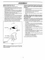
SAFETY RULES
_I,
SAFE OPERATION PRACTICES FOR RIDE-ON MOWERS ,_
IMPORTANT: THIS CUTTING MACHINE IS CAPABLE OF AMPUTATING HANDS AND FEET AND THROWING OBJECTS.
FAILURE TO OBSERVE THE FOLLOWING SAFETY INSTRUCTIONS COULD RESULT IN SERIOUS INJURY OR DEATH.
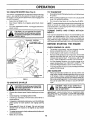
Avoid starting or stopping on a slope. If tires lose traction,
disengage the blades and proceed slowly straight down
the slope.
DO NOT:
I. GENERAL
•
•
OPERATION
Read, understand, and follow all instructions in the manuar
and on the machine before starting.
Only allow responsible adults, who are familiar with the
instructions, to operate the machine.
Clear the area of objects such as rocks, toys, wire, etc.,
which could be picked up and thrown by the blade.
Be sure the area is clear of other people before mowing.
Stop machine if anyone enters the area.
Nevercarry passengers.
Do not mow in reverse unless absolutely necessary.
Always look down and behind before and while backing.
Be aware of the mower discharge direction and do not point
itat anyone. Do not operate the mower without either the
entire grass catcher or the guard in place.
Slow down before turning.
Never leave a running machine unattended. Always turn
off blades, set parking brake, stop engine, and remove
keys before dismounting.
Turn off blades when not mowing.
Stop engine before removing grass catcher or unclogging
chute.
Mow only in daylight or good artificial light.
Do not operate the machine while under the influence of
alcohol or drugs.
Watch for traffic when operating near or crossing roadways.
Use extra ca re when leading or unloading the machine into
a trailer or truck.
Data indicates that operators, age 60 years and above, are
involved in a large percentage of riding mower-related
injuries. These operators should evaluate their ability to
operate the riding mower safely enough to protect themselves and others from serious injury.
Keep machine free of grass, leaves or other debris buildup which can touch hot exhaust / engine parts and bum.
Do not allow the mower deck to plow leaves
or other debris which can cause build-up to occur, Clean
any oil or fuel spillage before operating or storing the
machine.
Allow
machine
to
cool
before
storage.
II. SLOPE
•
III. CHILDREN
Tragic accidents can occur if the operator is not alert to the
presence of children. Children are often attracted to the
machine and the mowing activity. Neverassume thatchildren
will remain where you last saw them.
Keep children out of the mowing area and under the
watchful care of another responsible adult.
Be alert and turn machine off if children enter the area.
Before and when backing, look behind and down for small
children.
Never carry children. They may fall off and be seriously
injured or interferewith safe machine operation.
•
Never allow children to operate the machine.
•
Use extra care when approaching blind corners, shrubs,
trees, or other objects that may obscure vision.
IV. SERVICE
Use extra care in handling gasolineand otherfuels. They
are flammable and vapors are explosive.
- Use onlyan approved container.
- Never remove gas cap or add fuel with the engine
running. Allow engine to cool before refueling. Do not
smoke.
- Never refuel the machine indoors.
- Never store the machine or fuel container inside where
there is an open flame, such as a water heater.
Never run a machine inside a closed area.
Keep nuts and bolts, especially blade attachment bolts,
tight and keep equipment in good condition.
Never tamper with safety devices, Check their proper
operation regularly.
Keep machine free of grass, leaves, or other debhs buildup. Clean oil orfuel spillage. Allow machine to cool before
storing.
Stop and inspect the equipment if you strike an object.
Repair, if necessary, before restarting.
Never make adjustments or repairs with the engine
running.
Grass catcher components are subject to wear, damage,
and deterioration, which could expose moving parts or
allow objects to be thrown. Freguentlycheckcomponents
and replace with manufacturer's recommended parts,
when necessary.
Mower blades are sharp and can cut. Wrap the blade(s)
or wear gloves, and use extra caution when servicing
them.
Check brake operation frequently. Adjust and service
as required.
OPERATION
Slopes are a maior factor relatedto loss-of-control and tipover
accidents,whichcan result_nsevere injuryor death. AJlslopes
requireextracaution, If you cannot back up theslope or if youfeel
uneasyon it, do not mow it.
DO:
•
•
Do not turn on slopes unless necessary, and then, turn
slowly and gradually downhill, if possible.
Do not mow near drop-offs, ditches, or embankments.
The mower could suddenly turn over ifa wheel is over the
edge of a cliff or ditch, or if an edge caves in.
Do not mow on wet grass. Reduced traction could cause
sliding.
Do not try to stabilize the machine by putting your foot on
theground.
Do not use grass catcher on steep slopes.
Mow up and down slopes, not across.
Remove obstacles such as rocks, tree limbs, etc,
Watch for holes, ruts, or bumps. Uneven terrain could
overturn the machine. Ta// grass can hide obstacles,
Use slow speed. Choose a low gear so that you will not
have to stop or shift while on the slope.
Follow the manufacturer's recommendations for wheel
weights or counterweights to improve stability.
Use extra care with grass catchers or other attachments.
These can change the stability of the machine.
Keep all movement on the slopes slowand gradual Do
not make sudden changes in speed or direction.
2
SAFETY
!Safe Operation
RULES
Practices
for Ride-On
Mowers
Look for this symbol to point out important safety precautions.
It means
CAUTIONlt!
BECOMEALERT!!!
YOUR
SAFETY IS INVOLVED.
Be sure the area is clear of other people before mowing.
Stop machine if anyone enters the area.
Never carry passengers or children even with the blades
off.
Do not mow in reverse unless absolutely necessary. Always look down and behind before and while backing.
Never carry children. They may fall off and be seriously
injured or interfere with safe machine operation.
Keep children out of the mowing area and under the
watchful care of another responsible adult.
Be aled and turn machine off if children enter the area.
CAUTION: In order to prevent acciden.talstarting when setting up, transporting, adjusting or making repairs, always disconnect spark plug wire and
place wire where itcan not contact spark
plug.
Before and when backing, look behind and down for small
children.
&
Mow up and down slopes (15 ° Max), not across.
Remove obstacles such as rocks, tree limbs, etc.
CAUTION: Do not coast down a hill in
neutral, you may lose control of the
tractor.
Watch for holes, ruts, or bumps. Uneven terrain could
overturn the machine. Tall grass can hide obstacles.
Use slow speed. Choose a low gear so that you will not have
to stop or shift while on the slope.
Avoid starting or stopping on a slope. If tires lose traction,
disengage the blades and proceed slowly straight down
the slope.
If machine stops while going uphill, disengage blades, shift
into reverse and back down slowly.
Do not turn on slopes unless necessary, and then, turn
slowly and gradually downhill, if possible.
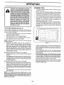
WARNING
Engine exhaust, some of its constituents, and certain vehicle components contain or emit chemicals
known to the State of California to cause cancer and
birth defects or other reproductive harm.
WARNING
Battery posts, terminals and related accessories
contain lead and lead compounds, chemicals known
to the State of California to cause cancer and birth
defects or other reproductive harm. Wash hands
after handling.
3
I
PRODUCT
i
SPECIFICATIONS
GASOLINE CAPACITY
AND TYPE:
1.25 GALLONS
UNLEADED REGULAR
OILTYPE (API-SF-SJ}:
SAE 30 (above 32°F)
SAE 5W-30 (below 32°F)
=OILCAPACITY:
SPARK PLUG:
(GAP: .030")
_ROUND SPEED (MPH):
TIRE PRESSURE:
Should you experience any problem you cannot easily
remedy, please contact your nearest authorized service
center/department. We have competent, well-trained technicians and the proper tools to service or repair this tractor.
Please read and retain this manual. The instructions will
enable you to assemble and maintain your tractor properly.
Always observe the "SAFETY RULES".
3 PINTS
CHAMPION RCt2YC
CUSTOMER
FORWARD:
1st
2nd
3rd
4th
5th
REVERSE:
1.1
2.2
3.3
4.4
4.9
1.4
FRONT:
REAR:
14 PSI
12 PSI
_HARGING SYSTEM:
3 AMPS BAlq'ERY
5 AMPS HEADLIGHTS
}ATTERY:
AMP/HR:
MIN. CCA:
CASESIZE:
BLADE BOLT TORQUE:
CONGRATULATIONS on yourpurchaseofanewtractor.
It
has been designed, engineered and manufactured to give
you the best possible dependability and performance.
RESPONSIBILITIES
Read and observe the safety rules.
Follow a regular schedule in maintaining, caring forand
using your tractor.
Follow the instructions under "Customer Responsibilities" and "Storage" sections of this owner's manual.
WARNING: This tractor is equipped with an internal combustion engine and should not be used on or near any
unimproved forest-covered, brush-covered or grass-covered land unless the engine's exhaust system is equipped
with a spark arrester meeting applicable local or state laws
(if any), If a spark arresteris used, it should be maintained
in effective working order by the operator.
28
230
U1R
A spark attester for the muffler is available through your
nearest authorized service center/department
(See REPAIR PARTS section of this manual).
27-35 FT. LBS.
TABLE OF CONTENTS
SERVICE AND ADJUSTMENTS .............................
STORAGE ...................................................................
TROUBLESHOOTING .............................................
REPAIR PARTS ......................................................
WARRANTY ............................................................
SAFETY RULES ........................................................
2-3
PRODUCT SPECIFICATIONS .......................................
4
CUSTOMER RESPONSIBILITIES ...................... 4, 14-18
ASSEMBLY ................................................................
6-8
OPERATION .............................................................
9-13
MAINTENANCE SCHEDULE .......................................
14
4
19--23
24
25-26
28-43
4546
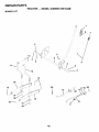
UNASSEMBLED
PARTS
I
Steering Wheel
Seat
\
\
\
\
\
(1) Washer
17/32 x 1-3/16 x 12 Gauge
&:b
(1) Lock
Washer 1/2
Steering Wheel
Insert
Steering
Boot
Steering Wheel
Adapter
Steering
Extension
Shaft
(1) Oil Drain Tube
For Future Use
Keys
llll Keys
Slope Sheet
(1) Large Flat Washer
(1) Locknut
1/2-20
@
(1) Hex Bolt
1/4-28 x 1-1/4
(1) Locknut
1/4-28
5
ASSEMBLY
Your new tractor has been assembled at the factory with exception of those parts left unassembled for shipping purposes. To
ensure safe and proper operation of your tractor all parts and hardware you assemble must be tightened securely. Use the
correct tools as necessary to insure proper tightness.
TOOLS
REQUIRED
FOR ASSEMBLY
A socket wrench set will make assembly easier. Standard
wrench sizes are listed.
(2) 1/2" wrenches
Pliers
(1) 9/16" wrench
Tire pressuregauge
Utility knife
When rig ht or left hand is mentioned in this manual, it means
when you are in the operating position (seated behind the
steering wheel).
TO REMOVE
CARTON
UNPACK
•
•
•
TRACTOR
STEERING
STEERING
WHEEL
FROM
BOOT
/
CARTON
Remove all accessible loose parts and parts cartons
from carton.
//'/L_TABS
ADAPTER
EXTENSION
Cut, from top 1obottom, along lines on all four corners
of carton, and lay panels flat.
Check for any additional loose parts or cartons and
remove.
BEFORE REMOVING TRACTOR
SKID
ATTACH
STEERING
WHEEL
SHAFT
FROM
(See Fig. 1)
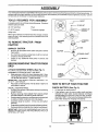
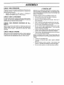
ASSEMBLE EXTENSION SHAFT AND BOOT
•
Slide extension shaft onto lower steering shaft. Align
mounting holes in extension and lower shaftsand install
1/4 hex bolt and Iocknut. Tighten securely.
IMPORTANT: TIGHTEN BOLT AND NUT SECURELY TO
10-12 FT. LBS TORQUE.
•
Place tabs of steering boot over tab slots in dash and
push down to secure.
FIG. 1
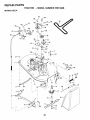
HOW TO SET UP YOUR TRACTOR
CHECK
BATTERY
(See Fig. 2)
Lift seat pan to raised position.
If this battery is put into service after month and year
indicated on label (label located between terminals)
charge battery for minimum of one hour at 6-10 amps.
(See "BATTERY" in the Customer Responsibilities section of this manual for charging instructions).
INSTALL STEERING WHEEL
•
Positionfront wheels of the tractor so they are pointing
straight forward.
Remove steering wheel adapter from steering wheel
and slide adapter onto steering shaft extension.
•
Positionsteering wheel so cross bars are horizontal (left
to right) and slide inside boot and onto adapter.
•
Assemble large flat washer, 1/2 hex nut and tighten
securely.
Snap steering wheel insert intocenterof steeringwheel.
•
RemoveprotectivematedalsfromtractorhoodandgrilL
IMPORTANT: CHECK FOR AND REMOVE ANY STAPLES
IN SKID THAT MAY PUNCTURE TIRES WHERE TRACTOR
IS TO ROLL OFF SKID.
SEAT PAN
LABEL
FIG. 2
6
ASSEMBLY
INSTALL
SEAT
(See Fig. 3)
TO ROLL TRACTOR OFF SKID (See Operation
section, page 10, for location and function of
controls)
Adjust seat before tightening adjustment bolt.
Remove adjustment bolt, lock washer and fiat washer
securing seat to cardboard packing and set aside for
assembly of seat to tractor.
Pivot seat upward and remove from the cardboard
packing. Remove the cardboard packing and discard.
Place seat on seat pan so head of shoulder bolt is
positioned over large slotted hole in pan.
Push down on seat to engage shoulder bolt in slot and
pull seat towards rear of tractor.
•
Pivot seat and pan forward and assemble adjustment
bolt, Iockwasher and flat washer loosely. Do not tighten
•
Lower seat into operating position and sit on seat.
Slide seat until a comfortable position is reached which
allows you to press clutch/brake pedal all the way down.
•
Get off seat without moving its adjusted position.
Raise seat and tighten adjustment bolt securely.
--
_
•
Remove banding holding deflector shield up against
tractor.
TO DRIVE TRACTOR OFF SKID (See Operation section, page 10, for location and function of controls)
AWARNING: Before starting, read, understand and follow
all instructions in the Operation section of this manual. Be
sure tractor is in a well-ventilated area. Be sure the area in
front of tractor is clear of other people and objects.
Be sure all the above assembly steps have been
completed.
Check engine oil level and fill fuel tank with gasoline.
Sit on seat in operating position, depress clutch/brake
pedal and set the parking brake.
Place gear shift lever in neutral (N) position.
Press lift lever plunger and raise attachment lift lever to
its highest position.
Start the engine. After engine has started, movethrottle
control to idle position.
Depress clutch/brake pedal into full "BRAKE" position
and hold. Move gearshift lever to 1st gear.
Slowly release clutch/brake pedal and slowly drive
tractor off skid.
/SEAT
SHOULDER
BOLT
FLAT
Press lift lever plunger and raise attachment lift lever to
its highest position.
Release parking brake by depressing clutch/brake pedal.
Place gearshift lever in neutral (N) position.
Roll tractor forward off skid.
Apply brake to stop tractor, set parking brake and place
gearshift lever in neutral position.
Turn ignition key to "OFF" position.
Continue with the instructions that follow.
WASHER
LOCK WASHER_
F
_DJUSTMENT
IOLT
FIG. 3
NOTE: You may now roll or drive your tractor off the skid.
Follow the appropriate instruction below to remove the
tractor from the skid.
7
ASSEMBLY
CHECK
TIRE
PRESSURE
/ CHECKL IS T
The tires on your tractor were ovednflated at the factory for
shipping purposes. Correct tire pressure is important for
best cutting performance.
Reduce tire pressure to PSI shown in "PRODUCT
SPECIFICATIONS" section of this manual.
CHECK
DECK
BEFORE YOU OPERA TEAND ENJOY YOUR NEW TRACTOR, WE WISH TO ASSURE THAT YOU RECEIVE THE
BEST PERFORMANCEAND SA TISFACTION FROM THIS
QUALITYPRODUCT.
PLEASE REVIEW THE FOLLOWING CHECKLIST:
LEVELNESS
,/
./
/
For best cutting results, mower housing should be properly
leveled. See "TO LEVEL MOWER HOUSING" in the Service
and Adjustments section of this manual.
CHECK
BELTS
FOR
PROPER
POSITION
•/
,/
OF ALL
,/
See the figures that are shown for replacing motion and
mower blade drive belts in the Service and Adjustments
section of this manual
Verify that the belts are routed
correctly.
CHECK
BRAKE
,/
SYSTEM
,/
After you learn how to operate your tractor, check to see that
the brake is properly adjusted. See ''TO ADJUST BRAKE"
in the Service and Adjustments section of this manual.
All assembly instructions have been completed.
No remaining loose parts in carton.
Batteryisproperlypreparedandcharged.
(Minimum1
hour at 6 amps).
Seat is adjusted comfortably and tightened securely.
All tires are properly inflated. (For shipping purposes,
the tires were overinflated at the factory).
Be sure mower deck is properly leveled side-to-side/
front-to-rear for best cutting results. (Tires must be
properly inflated for leveling).
Check mower and drive belts. Be sure they are routed
properly around pulleys and inside all belt keepers.
Check wiring. See that all connections are still secure
and wires are properly clamped.
WHILE LEARNING HOW TO USE YOUR TRA CTOR, PAY
EXTRA ATTENTION TO THE FOLLOWING IMPORTANT
ITEMS:
,/
,/
,/
,/
8
Engine oil is at proper level.
Fuel tank is filled with fresh, clean, regular unleaded
gasoline.
Become familiar with all controls - their location and
function. Operate them before you start the engine.
Be sure brake system is in safe operating condition.
OPERATION
These symbols may appear on your tractor or in literature supplied with the product. Learn and understand their meaning.
I- ;I
BATTERY
ENGINE ON
CAUTION OR
WARNING
ENGINE OFF
REVERSE
FORWARD
OIL PRESSURE
LIGHTS ON
Ixl
FUEL
CHOKE
FAST
SLOW
OVER TEMP
LIGHT
@
MOWER HEIGHT
PARKING BRAKE
LOCKED
!
w
UNLOCKED
MOWER LIFT
R N H
ATFACHMENT
CLUTCH ENGAGED
REVERSE
NEUTRAL
ATTACHMENT
IGNITION
HIGH
LOW
KEEP AREA CLEAR
PARKING BRAKE
SLOPE HAZARDS
(SEE SAFETY RULES SECTION)
CLUTCH DISENGAGED
FREE WHEEL
(Automatic Models only)
DANGER, KEEP HANDS AND FEET AWAY
9
OPERATION
KNOW YOUR TRACTOR
READ THIS OWNER'S
MANUAL
AND SAFETY
RULES BEFORE
OPERATING
YOUR TRACTOR
Compare the illustrations with your tractor to familiarize you rself with the locations of various controls and adjustments. Save
this manual for future reference.
ATTACHMENT
IGNITION
CLUTCH
LEVER
SWITCH
......
_-
POSITION
LEVER
PLUNGER
ATTACHMENT
LIFT LEVER
MOWER DECK
HEIGHT ADJUSTMENT
POSITIONS
PARKING
BRAKE
FIG. 4
Our tractors conform to the safety standards of the American National Standards institute.
ATTACHMENT CLUTCH LEVER: Used to engage the
mower blades, orotherattachments mounted to your tractor.
LIGHT SWITCH POSITION: Turns the headlights on and
Off.
GEARSHIFT LEVER: Selects the speed and direction of
tractor.
ATTACHMENT LIFT LEVER: Used to raise, lower, and
adjustthe mower deck or other attachments mounted to your
tractor.
LIFT LEVER PLUNGER: Used to release attachment lift
lever when changing its position.
IGNITION SWITCH: Used for starting and stopping the
engine.
THROTTLE/CHOKE
CONTROL: Used for starting and
controllingengine speed.
CLUTCH/BRAKE PEDAL: Used for declutching and braking the tractor and starting the engine.
PARKING BRAKE: Locks clutch/brake pedal intothe brake
position.
10
OPERATION
The operation of any tractor can result in foreign objects thrown into the eyes, which can
resu It in severe eye damage. Always wear safety glasses or eye shields while operating
your tractor or performing any adjustments or repairs. We recommend a wide vision
safety mask over spectacles or standard safety glasses.
IMPORTANT: LEAVING THE IGNITION SWITCH IN ANY
POSITION OTHER THAN "OFF" WILL CAUSE THE BATTERY
TO BE DISCHARGED, (DEAD).
HOW TO USE YOUR TRACTOR
TO SET
PARKING
BRAKE
(See Fig. 5)
NOTE: Under certain conditions when tractor is standing
idle with the engine ru n ning, hot engine exhaust gases may
cause "browning" of grass. To eliminate this possibility,
always stop engine when stopping tractor on grass areas.
Your tractor is equipped with an operator presence sensing
switch. When engine isrunning,any attempt by the operator
to leave the seat without first setting the parking brake will
shut oft the engine.
Depress clutch/brake pedal into full "BRAKE" position
and hold.
I
Place parking brake lever in "ENGAGED" position and
release pressu re from clutch/brake pedal. Pedal should
remain in "BRAKE" position. Make sure parking brake
will hold tractor secure.
ATTACHMENT
CLUTCH
"ENGAGED"
POSITION
THROTTLE/CHOKE'_"_
CONTROL LEVER
TO USE THROTTLE
KEY
TO MOVE FORWARD
(See Fig. 5)
IDISENGAGED"
TION
PARKING BRAKE
"ENGAGED"
POSITION
PARKING BRAKE
"DISENGAGED"
POSITION
TO ADJUST
MOWER BLADESTo stop mower blades, move attachment clutch lever to
"DISENGAGED" position.
GROUND DRIVE -
Move throttle control to slow position.
NOTE: Failure to move throttle control to slow position and
allowing engine to idle before stopping may cause engine to
"backfire".
•
Never use choke to stop engine.
CUTTING
HEIGHT
The cutting height range is approximately 1- 1/2 to 4". The
heights are measured from the ground to the blade tip with
the engine not running. These heights are approximate and
may vary depending upon soil conditions, height of grass
and types of grass being mowed.
The ave rage lawn should be cut to,app roximately 2-1/2
inches during the cool season and to over 3 inches
during hot months. For healthier and better looking
lawns, mow often and after moderate growth,
For best cutting performance, grass over 6 inches in
height should be mowed twice. Make the first cut
relatively high; the second to desired height.
To stop ground drive, depress clutch/brake pedal into
full "BRAKE" position.
Move gearshift lever to neutral (N) position.
ENGINE -
Turn ignition key to "OFF" position and remove key.
Always remove key when leaving tractor to prevent
unauthorized use.
MOWER
The position of the attachment lift lever determines the
cutting height.
Grasp lift lever.
•
Press plunger with thumb and move lever to desired
position.
(See Fig. 5)
•
AND BACKWARD
(See Fig. 5)
FIG.5
STOPPING
(See Fig. 5)
The direction and speed of movement is controlled by the
gearshift lever.
•
Start tractor with clutch/brake pedal depressed and
gearshift lever in neutral (N) position.
•
Move gearshift lever to desired position.
•
Slowly release clutch/brake pedal to start movement.
IMPORTANT: BRING TRACTOR TO A COMPLETE STOP
BEFORE SHIFTING OR CHANGING GEARS. FAILURE TO DO
SOWILLSHORTEN THE USEFUL LIFEOFYOUR TRANSAXLE.
GEARSHIFT
CLUTCH/BRAKE
PEDAL
"DRIVE" POSITION
CONTROL
Always operate engine at full throttle.
•
Operating engine at less than full throttle reduces the
batterycharging
rate.
•
Full throttle offers the best bagging and mower performance.
LEVER
IGNITION
CAUTION: Always stop tractor completely, as described above, before
leaving the operator's position; to
empty grass catcher, etc.
11
OPERATION
TO OPERATE
MOWER
TO TRANSPORT
(See Fig. 6)
Raise attachment lift to highest position with attachment
lift control.
Your tractor is equipped with an operator presence sensing
switch. Any attempt by the operator to leave the seat with
the engine running and the attachment clutch engaged will
shut off the engine.
Select desired height of cut.
Start mower blades by engaging attachment clutch
control.
•
When pushing or towing your tractor, be sure gearshift
lever is in neutral (N) position.
Do not push or tow tractor at more than five (5) MPH.
NOTE: To protect hood from damage when transporting your
tractor on a truck or a trailer, be sure hood is closed and
secured to tractor. Use an appropriate means of tying hood
to tractor (rope, cord, etc.).
TO STOP MOWER BLADES - disengage attachment
clutch control.
I
TOWING
MENTS
I
CAUTION: Do not operate the mower
without either the entire grass catcher,
on mowers so equipped, or the deflector
shield in place.
"ENGAGED"
I
I
POSITION
BEFORE
CHECK
POSITION
ATTACHMENT
CLUTCH LEVER
_
FIG. 6
I
•
•
_
ON HILLS
with slopes greater than f 5° and do not
CAUTION:
drive
acrossDonotdriveupordownhills
any slope,
ATTACH-
STARTING
ENGINE
OIL
THE ENGINE
LEVEL
ADD GASOLINE
Fill fuel tank to bottom of filler neck. Do not ove frill. Use
fresh, clean, regular unleaded gasoline with a minimum
of 87 octane. (Use of leaded gasoline will increase
carbon and lead oxide deposits and reduce valve life).
Do not mix oil with gasoline. Purchase fuel in quantities
that can be used within 30 days to assure fuel freshness.
DEFLECTOR
SHtELD
TO OPERATE
OTHER
The engine in your tractor has been shipped, from the
factory, already filled with summer weight oil,
Check engine oil with tractor on level ground.
Remove oil fill cap/dipstick and wipe clean, reinsert the
dipstick and screw cap tight, wait for a few seconds,
remove and read oil level. If necessary, add oil until
"FULL" mark on dipstick is reached. Do not overfill.
For cold weather operation you should change oil for
easier starting (See "OIL VISCOSITY CHART" in the
Customer Responsibilities section of this manual),
To change engine oil, see the Customer Responsibilities
section in this manual.
OW
"DISENGAGED"
POSITION
AND
Tow only the attachments that are recommended by and
comply with specifications of the manufacturer of your
tractor. Use common sense when towing. Too heavy of a
load, while on a slope, is dangerous. Tires can lose traction
with the ground and cause you to lose control of your tractor.
ATTACHMENT
LIFT
HIGH POSITION
_
CARTS
I
I
Move gearshift lever to 1st gear. Be sure you have
allowed room for tractor to roll slightly as you restart
movement.
•
To restart movement, slowly release parking brake and
clutch/brake pedal.
Make all turns slowly.
fuel. Do not store, spill or use gasoline
CAUTION:
off any spilled oil or
near
an openWipe
flame,
IMPORTANT:
WHEN OPERATING
IN TEMPERATURES
BELOW32°F(0°C),
USE FRESH, CLEAN WINTER GRADE
GASOLINE
TO HELP INSURE GOOD COLD WEATHER
STARTING.
Choose the slowest speed before starting up or down
hills.
Avoid stopping or changing speed on hills.
If slowing is necessary, move throttle control lever to
slower position.
If stopping is absolutely necessary, push clutch/brake
pedal quickly to brake position and engage parking
brake.
•
6
12
I
OPERATION
MOWING
&
TO START
CAUTION: Alcohol blended fuels (called
gasohol or using ethanol or methanol)
can attract moisture which leads to separation and formation of acids during
storage. Acidic gas can damage the fuel
system of an engine while in storage. To
avoid engine problems, the fuel system
should be emptied before storage of 30
days or longer. Drain the gas tank, start
the engine and let it run until the fuel
lines and carburetor are empty. Use
fresh fuel next season. See Storage
Instructions for additional information.
Never use engine or carburetor cleaner
products in the fuel tank or permanent
damage may occur.
ENGINE
•
•
(See Fig. 5)
TIPS
Tire chains cannot be used when the mower housing is
attached to tractor.
Mower should be properly leveled for best mowing
performance. See'q-O LEVEL MOWER HOUSING" in
the Service and Adjustments section of this manual.
The left hand side of mower should be used for trimming.
Drive so that clippings a re discharged onto the area that
has been cut. Have the cut area to the right of the
machine. This will result in a more even distribution of
clippings and more uniform cutting.
When mowing large areas, start by turning to the right so
that clippings will discharge away from shrubs, fences,
driveways, etc. After one or two rounds, mow in the
opposite direction making left hand turns until finished
(See Fig. 7 ).
f
l
When starting the engine for the first time or Jfthe engine has
run out of fuel, it will take extra cranking time to move fuel
from the tank to the engine.
•
Sit on seat in operating position, depress clutch/brake
pedal and set parking brake.
•
Place gear shift lever in neutral (N) position.
Move attachment clutch to "DISENGAGED" position.
Move throttle control to choke position.
e
NOTE: Before starting, read the warm and cold starting
procedures below.
Insert key into ignition and turn key clockwise to
"START" position and release key as soon as engine
starts. Do not run starter continuously for more than
fifteen seconds per minute. If the engine does not start
after several attempts, move throttle contro_ to fast
position, wait a few minutes and try again, tf engine still
does not start, move the throttle control back to the
choke position and retry.
f
C
,i
J
FIG. 7
•
WARM WEATHER STARTING (50 ° F and above)
When engine starts, move the throttle control to the fast
position.
•
The attachments and ground drive can now be used. If
the engine does not accept the load, restart the engine
and allow it to warm up for one minute using the choke
as described above.
•
COLD WEATHER STARTING ( 50 ° F and below)
•
When engine starts, allow engine to run with the throttle
control in the choke position until the engine runs
roughly, then move throttle control to fast position. This
may require an engine warm-up period from several
seconds to several minutes, depending on the temperature.
•
The attachments can also be used during the engine
warm-up period.
NOTE: If at a high altitude (above 3000 feet) or in cold
temperatures (below 32 F) the carburetor fuel mixture may
need to be adjusted for best engine performance. See "TO
ADJUST CARBURETOR" in the Service and Adjustments
section of this manual.
13
If grass is extremely tall, it should be mowed twice to
reduce load and possible fire hazard from dried clippings. Make f{rst cut relatively high; the second to the
desired height.
Do not mow grass when it is wet. Wet grass will plug
mower and leave undesirableclumps. AIIowgrasstodry
before mowing.
Always operate engine at full throttle when mowing
to assure better mowing performance and proper discharge of materiaL Regulate ground speed by selecting
a low enough gear to give the mower cutting performance as well as the quality of cut desired.
When operating attachments, select a ground speed
that will suit the terrain and give best performance of the
attachment being used.
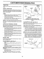
CUSTOMER
MAINTENANCE
RESPONSIBILITIES
SCHEDULE
FILL IN DATES
AS YOU COMPLETE
REGULAR
SERVICE
T
sERvicE
DATES
Check
8rake
Operation
Check
Tire Pressure
Check
Operator
Presence
and
Interlock Systems
Check for Loose Fasteners
_#
V'5
I_
Lubrication Chart
I_
Check
Battery Level
Sharpen/Replace
Mower
R
E
Blades
Clean
Battery and Terminals
Check
Transaxle
Check
V-BelIs
Check
Engine
_3
I_
Cooling
If
V'
Oil Level
_
Change
Engine
Oil (with oil filter)
Change
Engine
Oil (without
oil filter)
Vwl,;
V r
_.2
If
Clean Air Filter
G
Clean
Air Screen
Inspect
E
Muffler/Spark
Replace
Arrester
Oil Filter (If equipped)
Clean Engine
Cooling
Fins
Replace
Spark Plug
If
Replace
Air Filter Paper Cartridge
11_2
Replace
Fuel Filter
3 - Replace blades more often when mowing in sandy soil
4 - Not required if equipped with maintenance-free battery
5 - Tighten front axle pivot bolt to 35 il.-Ibs, maximum.
Do not ovenigl_ten.
1 - Change more often when operating under a heavy load or
in high ambient temperatures.
2 - Service more often when operating in dirty or dusty conditions.
LUBRICATION
GENERAL
CHART
RECOMMENDATIONS
_SPINDLE
ZERK
The warranty on this tractor does not cover items that have
been subjected to operator abuse or negligence. To receive
full value from the warranty, operator must maintain tractor
as instructed in this manual.
0)FRONT
BEARING
;-_-;
ZERK _.
ZERK
_ (i)FRONT WHEEL
BEARING ZERK
Some adjustments will need to be made periodically to
properly maintain your tractor.
All adjustments in the Service and Adjustments section of
this manual should be checked at least once each season.
•
Once a year you should replace the spark plug, clean or
replace air filter, and check blades and belts for wear. A
new spark plug and clean air filter assure proper air-fuel
mixture and help yourengine run betterand last longer.
BEFORE
•
•
•
•
•
EACH
USE
Check engine oil level.
Check brake operation.
Check tire pressure.
Checkoperatorpresenceand
interlocksystems for proper operation.
Check for loose fasteners.
(t)GENERAL
PURPOSE GREASE
(2)REFER TO CUSTOMER RESPONSIBILITIES
SECTION
"ENGINE"
IMPORTANT:
DO NOT OIL OR GREASE THE PIVOT POINTS
WHICH HAVE SPECIAL NYLON BEARINGS.
VISCOUS LUSRICANTS WILL ATTRACT DUST AND DIRT THAT WILL SHORTEN
THE LIFE OF THE SELF*LUBRICATING
BEARINGS,
IF YOU
FEEL THEY MUST BE LUBRICATED,
USE ONLY A DRY, POWDERED GRAPHITE
TYPE LUBRICANT
SPARINGLY.
14
CUSTOMER
RESPONSIBILITIES
TRACTOR
BRAKE
MANDREL
ASSEMBLY
TRAILING
EDGE UP
Always observe safety rules when performing any maintenance.
OPERATION
CENTER
HOLE
(
If tractor requires more than six (6) feet stopping distance at
high speed in highest gear, then brake must be adjusted.
(See'q'O ADJUST BRAKE" in the Service and Adjustments
section of this manual).
LOCK WASHER
STAR
TIRES
•
•
•
Maintain proper air pressure in alltires (See"PRODUCT
SPECIFICATIONS" section of this manual).
Keep tires free of gasoline, oil, or insect control chemicals which can harm rubber.
.J
_'
_
Avoid stumps, stones, deep ruts, sharp objects and
other hazards that may cause tire damage.
FLAT WASHER
BLADE BOLT
(GRADE 8)*
*A GRADE 8 HEAT TREATED BOLT CAN BE
IDENTIFIED BY SIX LINES ON THE BOLT HEAD.
NOTE: To seal tire punctures and prevent flat tires due to
slow leaks, tire sealant may be purchased from your local
parts dealer. Tire sealant also prevents tire dry rot and
corrosion.
TO SHARPEN
OPERATOR
NOTE: We do not recommend sharpening blade- but ifyou
do, be sure the blade is balanced.
PRESENCE
FIG. 8
SYSTEM
•
•
The blade can be sharpened with a file or on a grinding
wheel. Do not attempt to sharpen while on the mower.
To check blade balance, you will need a 5/8" diameter
steel bolt, pin, or a cone balancer. (When using a cone
balancer, follow the instructions supplied with balancer.)
/
For best results mower blades must be kept sharp. Replace
bent or damaged blades.
CENTER
BLADE REMOVAL
(See Fig. 8)
Raise mower to highest position to allow access to
blades.
IMPORTANT: TO ENSURE PROPER ASSEMBLY, CENTER
HOLE IN BLADE MUST ALIGN WITH STAR ON MANDREL
ASSEMBLY.
•
Tighten
IMPORTANT:
blade bolt securely
(27-35
HOLE
5/8" BOLT
OR PIN
Remove blade bolt, lock washer and flat washer securing blade.
Install new or resharpened blade with trailing edge up
towards deck as shown.
and flat washer
Fig. 9)
NOTE: Do not use a nail for balancing blade. The lobes of
the center hole may appear to be centered, but are not.
Slide blade on to an unthreaded portion of the steel bolt
or pin and hold the bolt or pin parallel with the ground. If
blade is balanced, it should remain in a horizontal
position. If either end of the blade moves downward,
sharpen the heavy end until the blade is balanced.
CARE
Reassemble
blade bolt, lock washer
exact order as shown.
(See
Care should be taken to keep the blade balanced. An
unbalanced blade will cause excessive vibration and eventual damage to mower and engine.
Be sure operator presence and interlock systems are working properly. If your tractor does not function as described,
repair the problem immediately.
•
The engine should not start unless the clutch/brake
pedal is fully depressed and attachement clutch control
is in the disengaged position.
When the engine is running, any attempt by the operator
to leave the seat without first setting the parking brake
should shut off the engine.
•
When the engine is running and the attachment clutch is
engaged, any attempt by the operator to leave the seat
should shut off the engine,
•
The attachment clutch should neveroperate unless the
operator is in the seat.
BLADE
BLADE
BLADE
FIG. 9
in
Ft. Lbs. torque).
BLADE BOLT IS GRADE 8 HEAT TREATED.
15
/
CUSTOMER
RESPONSIBILITIES
BATTERY
NOTE: Although multi-viscosity oils (5W30, 10W30 etc.)
improve starting in cold weather, these multi-viscosity oils
will result in increased oil consumption when used above
32°F. Check your engine oil level more frequently to avoid
possible engine damage from running low on oil.
Your tractor has a battery charging system which is sufficient for normal use. However, periodic charging of the
battery with an automotive charger will extend its life.
Keep battery and terminals clean.
Keep battery bolts tight.
•
Keep small vent holes open.
Recharge at 6-10 amperes for 1 hour.
Change the oil after every 25 hours of operation or at least
once a year if the tractor isnot used for 25 hours in one year.
Check the crankcase oil level before starting the engine and
after each eight (8) hours of operation. Tighten oil fill cap/
dipstick securely each time you check the oil level.
NOTE: The original equipment battery on your tractor is
maintenance free. Do not attempt to open or remove caps or
covers. Adding or checking level of electrolyte is not
necessary.
TO CHANGE ENGINE OIL (See Figs. 10 and 11)
Determine temperature range expected before oil change.
All oil must meet API service classification SF-SJ.
•
Be sure tractor is on level surface.
TO CLEAN SATI-ERY AND TERMINALS
Corrosion and dirt on the battery and terminals can cause the
battery to "leak" power.
•
Disconnect SLACK batterycable first then RED battery
cable and remove battery from tractor.
Rinse the battery with plain water and dry.
•
Clean terminals and battery cable ends with wire brush
until bright.
Coat terminals with grease or petroleum jelly.
•
Reinstall battery (See "REPLACING BATTERY" in the
SERVICE AND ADJUSTMENTS section of this manual).
Oil will drain more freely when warm.
Catch oil in a suitable container.
Remove oil fill cap/dipstick. Be careful not to allow dirt
to enter the engine when changing oil.
Remove yellow cap from end of drain valve and install
the drain tube onto the fitting.
OIL DRAIN VALVE
CLOSED
AND
V-BELTS
POSITION
Check V-belts for deterioration and wear after 100 hours of
operation and replace if necessary. The belts are not
adjustable. Replace belts if they begin to slipfrom wear.
TRANSAXLE
COOLING
Keep transaxle free from build-up of dirtand chaff which can
restrictcooling.
TUBE
CAP
ENGINE
FIG. 11
LUBRICATION
Only use high quality detergent oil rated with API service
classification SF-SJ. Select the oil's SAE viscosity grade
according to your expected operating temperature.
SAE VISCOSITY
F
-20
-30
0
-20
TEMPERATURE
30
-10
RANGE
32
Unlock drain valve by pushing inward and turning counterclockwise.
To open, pull out on the drain valve.
After oil has drained completely, close and lock the drain
valve by pushing inward and turning clockwise until the
pin is in the locked position as shown.
GRADES
40
0
ANTICIPATED
60
10
BEFORE
80
20
NEXT
Remove the drain tube and replace the cap onto to the
bottom fitting of the drain valve.
Refill engine with oil through oil fill dipstick tube. Pour
slowly. Do not overfill. For approximate capacity see
"PROD UCT SPECIFICATIONS" section of this manual.
100
30
40
OIL CHANGE
FIG, 10
Use gauge on oil fill cap/dipstick for checking level. Be
sure dipstick cap is tightened securely for accurate
reading. Keep oil at "FULL" line on dipstick.
16
CUSTOMER
CLEAN
RESPONSIBILITIES
AIR SCREEN
AIR FILTER (See Fig. 13)
Air screen must be kept free of dirt and chaff to prevent
engine damage from overheating. Clean with a wire brush or
compressed air to remove dirt and stubborn dried gum fibers.
ENGINE
Yourengine will not run properly using a dirty air filter. Clean
the foam pre-cleaner after every 25 hours of operation or
every season. Service paper cartridge every 100 hours of
operation or every season, whichever occurs first.
Service air cleaner more often under dusty conditions.
Remove knob(s) and cover.
TO SERVICE PRE-CLEANER
Slide foam pre-cleaner off cartridge.
Wash it in liquid detergent and water.
Squeeze it dry in a clean cloth.
Satu rate it in engine oil. Wrap it in clean, absorbent cloth
and squeeze to remove excess oil.
If very dirty or damaged, replace pre-cleaner.
Reinstall pre-cleaner over cartridge.
•
Reinstall cover and secure with knob(s).
TO SERVICE CARTRIDGE
Remove cartridge nut.
Carefully remove cartridge to prevent debris from entering carburetor. Clean base carefully to prevent debris
from entering carburetor.
Clean cartridge bytapping gently on flat surface. If very
dirty or damaged, replace cartridge.
•
Reinstall cartridge, nut, precleaner, cover and secure
with knob(s).
IMPORTANT:
PETROLEUM SOLVENTS, SUCH AS
KEROSENE, ARE NOT TO BE USED TO CLEAN THE
CARTRIDGE. THEY MAY CAUSE DETERIORATION OF
THE CARTRIDGE. DO NOT OIL CARTRIDGE. DO NOT
USE PRESSURIZED AIR TO CLEAN OR DRY CARTRIDGE.
FINS (See Fig. 12)
COOLING
Remove any dust, dirt or oil from engine cooling fins to
prevent engine damage from overheating.
Remove screws from blower housing and lift housing
and dipstick tube assembly off engine.
Cover oil fill opening to prevent entry of dirt.
Use compressed air or stiff bristle brush to thoroughly
clean engine cooling fins.
To reassemble, reverse above procedure.
SCREWS
BLOWER
HOUSING
SCREWS
AIR SCREEN
OIL FILL
TUBE
ASSEMBLY
COVER.__,_
KNOB
ENGINE
COOLING
J
SPARK
PLUG
FINS
CARTRIDGE
FIG. 12
_/./NUT
_PAPER
FOAM
_
CARTRIDGE
PRE-CLEANER
FIG. 13
17
CUSTOMER
RESPONSIBILITIES
MUFFLER
CLAMP
Inspect and replace corroded muffler and spark arrester (if
equipped) as it could create a fire hazard and/or damage.
SPARK
PLUGS
CLAMP
Replace spark plugs at the beginning of each mowing
season or after every 100 hours of operation, whichever
occurs first. Spark plug type and gap setting are shown in
"PRODUCT SPECIFICATIONS" section of this manual.
IN-LINE
FUEL FILTER
FUEL
FILTER
FIG. 14
(See Fig. 14)
The fuel filter should be replaced once each season. If fuel
filter becomes clogged, obstructing fuel flow to carburetor,
replacement is required.
With engine cool, remove filter and plug fuel line sections.
•
•
•
_
CLEANING
Clean engine, battery, seat, finish, etc. of all foreign
matter.
Place new fuel filter in position in fuel line with arrow
pointing towards carburetor,
Be sure there are no fuel line leaks and clamps are
properly positioned.
Immediately wipe up any spilled gasoline.
•
Keep finished surfaces and wheels free of all gasoline,
oil, etc.
•
Protect painted surfaces with automotive type wax.
We do not recommend using a garden hose to clean your
tractor unless the electrical system, muffler, air filter and
carburetor are covered to keep water out. Water in engine
can result in a shortened engine life.
18
SERVICE AND ADJUSTMENTS
WARNING: TO AVIOD SERIOUS INJURY, BEFORE PERFORMING ANY SERVICE OR ADJUSTMENTS:
Depress clutch/brake pedal fully and set parking brake.
•
Place gearshift lever in neutral (N) position.
Place attachment clutch in "DISENGAGED" position.
Turn ignition key to "STOP" and remove key.
Make sure the blades and all moving parts have completely stopped.
Disconnect spark plug wire from spark plug and place wire where it cannot come in contact with
plug.
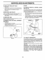
TRACTOR
TO REMOVE
MOWER
(See Fig. 15)
Mower willbe easierto remove from the rig ht side of tractor.
Place attachment clutch in "DISENGAGED" position.
•
Move attachment lift lever forward tOlower mower to its
lowest position.
Roll belt off engine pulley.
Remove small retainer spring, and lift clutch spring off
pulley bolt.
•
Removelargeretainerspring,
slidecollaroffandpush
housing guide out of bracket.
Disconnect anti-swaybar from chassis bracket by removing retainer spring.
Disconnect suspension arms from rear deck brackets
by removing retainer springs.
Disconnect front links from deck by removing retainer
springs.
•
Raise lift lever to raise suspension arms. Slide mower
out from under tractor.
IMPORTANT: IF AN A37-ACHMENT OTHER THAN THE
MOWER DECK IS TO BE MOUNTED ON THE TRACTOR, REMOVE THE FRONT LINKS AND HOOK THE
CLUTCH SPRING INTO SQUARE HOLE IN FRAME.
TO INSTALL
MOWER
(See Fig. 15)
Raise attachment lift lever to its highest position.
Slide mower under tractor with deflector shield to right
side of tractor.
•
•
•
•
SUSPENSION
Lower lift lever to its lowest position.
Connect front links to mower deck and secure with
retainer springs.
Connect suspension arms to rear deck brackets and
secure with retainer springs.
Connect anti-swaybar to chassis bracket and secure
with retainer spring.
Push clutch cable housing guide into bracket, slide collar
onto guide and secure with large retainer spring.
Install belt onto engine pulley.
ARMS
SMALL
ENGINE
PULLEY
CLUTCH
LINK
RETAINER
ANTI-SWAY
BAR
\
\
HOUSING
GUIDE
LARGE
RETAINER
SPRING
RETAINER
SPRINGS
(BOTH
SIDES)
DEFLECTOR
BRACKET
Fig. 15
19
SHIELD
SERVICE AND ADJUSTMENTS
TO LEVEL MOWER
When distance "D" is 1/8" to 1/2" lower at front than rea r,
tighten nuts "F" against trunnion on both front links.
To raise front of mower, loosen nut"F" from trunnion on
both front links. Tighten nut "E" on both front links an
equal number of turns. The two front links must remain
equal in length.
When distance"D" is 1/8" to 1/2" lower at front than rear,
tighten nut "F" against trunnion on both front links.
Recheck side-to-side adjustment.
HOUSING
Adjust the mower while tractor is parked on level ground or
driveway. Make su re tires are properly inflated (See "PRODUCT SPECIFICATfONS" section of this manual). Iftires are
over or underinflated, you will not properly adjust your
mower.
SIDE-TO-SIDE ADJUSTMENT (See Figs. 16 and 17)
•
Raise mower to its highest position.
At the midpoint of both sides of mower, measure height
from bottom edge of mower to ground. Distance"A"on
both sides of mower should be the same or within 1/4"
of each other.
•
J.
_ o,I MANDREL
If adjustment is necessary, make adjustment on one
side of mower only.
To raise one side of mower, tighten lift link adjustment
nut on that side.
To lower one side of mower, loosen lift link adjustment
nut on that side.
FIG. 18
BOTH FRONT LINKS MUST BE EQUAL IN LENGTH
NOTE: Three full turns of adjustment nut will change mower
height about 1/8".
•
Recheck measurements after adjusting.
SO]-rOM EDGE
OF MOWER
BOTTOM EDGE
OF MOWER
NUT "F"_
_GROUND
"E"
LIN_
FIG. 16
TRUNNION
Q
_
NUT
FRONT LINK__/_._
__
SUSPENSION
/
/
ARM
FIG. 19
o@
FT LINK
_.....-AOJUSTMEN1TO
--
__
REPLACE
MOWER
BLADE
DRIVE
BELT
(See Fig. 20)
NUT
The mower blade drive belt may be replaced without tools.
Park the tractor on level surface. Engage parking brake.
FIG. 17
FRONT-TO-BACK
ADJUSTMENT
(See Figs, 18 and 19)
IMPORTANT:
DECK MUST BE LEVELSIDE-TO-SIDE.
IF
THE FOLLOWING
FRONT-TO-BACK
ADJUSTMENT
IS
NECESSARY,
BE SURE TO ADJUST BOTH FRONT LINKS
EQUALLY
SO MOWER
WILL STAY LEVEL SIDE-TOSIDE.
BELT REMOVAL •
Place attachment clutch in "DISENGAGED" position.
Move attachment lift leverforward to lower mower to its
lowest position.
Roll belt off engine pulley.
•
Disconnect R.H. suspension arm from reardeck bracket
by removing retainer spring.
•
Work belt off both mandrel pulleys and idler pulleys.
•
Pull belt away from mower.
To obtain the best cutting results, the mower housing should
be adjusted so that the front is approximately 1/8" to 1/2"
lower than the rear when the mower is in its highest position.
Checkadjustment on right side of tractor. Measure distance
"D" directly in front and behind the mandrel at bottom edge
of mower housing as shown.
•
Before making any necessary adjustments, check that
both front links are equal in length.
If links are not equal in length, adjust one link to same
length as other link.
To lower frent of mower loosen nut"E" on both front links
an equal number of turns.
BELT INSTALLATION -
•
•
2O
Work new belt around both mandrel pulleys and idler
pulleys.
Install new belt into engine pulley grove.
Reconnect R.H. suspension arm and secure with retainer spnng.
Make sure belt is in all purley grooves and inside all belt
guides.
SERVICE AND ADJUSTMENTS
R,H. SUSPENSION
MANDREL
PULLEY
.
........
ARM
,,_
_jf-
i;
r
%_
Remove belt downward from around engine pulley.
Pull belt slack toward rear of tractor. Remove belt
upwards from transaxle pulley by deflecting belt keepers.
•
Remove belt from center span keeper and pull belt away
from tractor.
..
_
-
•
•
_-2"
_
_
ENGINE
PULLEY
BELT INSTALLATION •
Carefully work new belt down between transaxle belt
keepers and onto the input pulley.
Slide belt into the center span keeper.
Pull belt toward front of tractor and roll around the top
groove of engine pulley.
Install belt through stationary idler and clutching idler.
•
Make sure belt is in all pulley grooves and inside all belt
guides and keepers.
Install mower (See "TO INSTALL MOWER" in this
section of manual).
, PULLEYS
PULLEY
FIG. 20
TO ADJUST
BRAKE
(See Fig. 21)
Your tractor is equipped with an adjustable brake system
which is mounted on the right side of the transaxle.
STATIONARY
IDLER
If tractor requires more than six (6) feet stopping distance at
high speed in highest gear on a level dry concrete or paved
surface, then brake must be adjusted.
•
Depress clutch/brake pedal and engage parking brake.
•
Measure distance between brake operating arm and nut
"A" on brake rod.
•
If distance is other than 1-1/2", loosen jam nut and turn
nut "A" until distance becomes 1-1/2". Retighten jam nut
against nut "A".
Road test tractor for proper stopping distance as stated
above. Readjust if necessary. If stopping distance is
still greater than six (6) feet in highest gear, further
maintenance is necessary. Contact your nearest authorized service center/department.
TRANSAXLE
PULLEY
WITH PARKING BRAKE "ENGAGED"
FIG. 22
TO ADJUST
_
NUT "A"
.....
"_"_
/
JAM NUT
DRIVE
WHEEL
TOE-IN/CAMBER
The front wheel toe-in and camber are not adjustable on you r
tractor, if damage has occurred to affect the front wheel toein or camber, contact your nearest authorized service
center/department.
FIG. 21
MOTION
WHEEL ALIGNMENT
If steering wheel crossbars are not horizontal (left to right)
when wheels are positioned straight forward, remove steering wheel and reassemble per instructions in the Assembly
section of this manual.
FRONT
TO REPLACE
STEERING
BELT
TO REMOVE
(See Fig. 22)
(See Fig. 23)
Parkthe tractor on level surface. Engage parking brake. For
assistance, there isa belt installationguide decal on bottom
side of left footrest.
•
BELT REMOVAL Remove mower (See "TO REMOVE MOWER" in this
section of manual).
•
NOTE: Observe entire motion drive belt and position of all
belt guides and keepers.
•
Remove belt from stationary idler and clutching idler. 21 •
WHEEL
FOR
REPAIRS
Block up axle securely.
Remove axle cover, retaining ring and washers to allow
wheel removal (rear wheel contains a square key- Do not
lose).
Repair tire and reassemble.
On rearwheels only: align grooves in rearwheel hub and
axle. Insert square key.
Replace washers and snap retaining ring securely in axle
groove.
Replace axle cover.
SERVICE AND ADJUSTMENTS
NOTE: To sealtire punctures and prevent flattires due to
REPLACING
slow leaks, tire sealant may be purchased from your local
parts dealer. Tire sealant also prevents tire dry rot and
corrosion.
BA'R'ERY
(See Figs. 25 and 26)
WASHERS
AXLE COVER
-...Q.
Lift seat pan to raised position.
Disconnect BLACK battery cable first then RED battery
cable and carefully remove battery from tractor.
Install new battery with terminals in same position as old
battery.
First connect RED battery cable to positive (+) terminal
with hex bolt and keps nut as shown. Tighten securely.
Slide terminal cover over terminal.
SQUARE KEY(REAR_'
WHEEL ONL_
--""-
FIG. 23
TO START ENGINE
WITH A WEAK BATTERY
(See Fig. 24)
_
Connect BLACK grounding cable to negative (-) terminal
with remaining hex bolt and keps nut. Tighten securely.
explosive gases. Keep sparks, flame
and smokingLead-acid
materials
away from
batWARNING:
batteries
generate
teries. Always wear eye protection when
around batteries.
If your battery is too weak to start the engine, it should be
recharged. (See "BATTERY" in the CUSTOMER RESPONSIBILITIES section of this manual).
If "jumper cables"
thisprocedure:
are used for emergency
IMPORTANT:
YOUR
VOLT SYSTEM. THE
12 VOLT SYSTEM.
BATTERY TO START
starting,
SEAT PAN
follow
TRACTOR rs EQUIPPED WITH A 12
OTHER VEHICLE MUST ALSO BE A
DO NOT USE YOUR TRACTOR
OTHER VEHICLES.
TO ATTACH JUMPER CABLES o
•
Connect one end of the RED cable to the POSITIVE (+)
terminal of each battery(A-B), taking care not to short
against tractor chassis.
•
Connect one end of the BLACK cable to the NEGATIVE
(-) terminal (C) of fully charged battery.
Connect the other end of the BLACK cable (D) to good
chassis ground, away from fuel tank and battery.
FIG. 25
KEPS
TERMINAL
COVER
_-_/
NUT
HEX
TO REMOVE CABLES, REVERSE ORDER BLACK cable first from chassis and then from the fully
charged battery.
•
RED cable last from both batteries.
POSITIVE
(RED) CABLE
NEGATIVE
(BLACK) CABLE
FIG. 26
WEAK OR DEAD
BATTERY
FULLY CHARGED
BATTERY
FIG. 24
22
SERVICE
AND ADJUSTMENTS
ENGINE
TO REPLACE
HEADLIGHT
BULB
•
Raise hood.
Pull bulb holder out of the hole inthe backside of the grill.
TO ADJUST THROTTLE
(See Fig. 28)
Replace bulb in holder and push bulb holder securely
back into the hole in the backside of the grill.
Close hood.
INTERLOCKS
CABLE
The throttle control has been preset at the factory and
adjustment should not be necessary. Check adjustment as
described below before loosening cable. If adjustment is
necessary, proceed as fellows:
With engine not running, move throttle controlleverfrom
slow to choke position. Slowly move lever from choke
to fast position.
Check that holes "A" in governor control lever and hole
in governor plate line-up. If holes "A" are not aligned,
loosen clamp screw and move throttle cable until holes
are aligned. Tighten clamp screw securely.
AND RELAYS
Loose or damaged wiring may cause your tractor to run
poorly, stop running, or prevent it from starting.
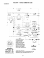
Check wiring. See electrical wiring diagram in the Repair
Parts section.
TO REPLACE
CONTROL
FUSE
Replace with 20 amp automotive-type plug-in fuse. The fuse
holder is located behind the dash.
TO REMOVE
HOOD
AND
GRILL
(See Fig. 27)
Raise hood.
Unsnap headlight wire connector.
•
Stand in front oftracter. Grasp hood at sides, tilt toward
engine and liftoff of tractor.
•
To replace, reverse above procedure.
\
!!
•
'_'\_,
GOVERNOR
CONTROL
PLATE
GOVERNOR
CONTROL LEVER
ASSEMBLY
"-.
o
il
HOOD
•
HEAOLIGH,
WIRE
CONNECTOR
HOLES
"A"
CLAMP
SCREW
THROTTLE
CABLE
FIG. 28
TO ADJUST
FIG. 27
CARBURETOR
The carburetor has been preset at the factory and adjustment should not be necessary. However, minoradjustment
may be required to compensate for differences in fuel,
temperature, altitude orload. If the carburetordoes need
adjustment, see engine manual.
High speed stop is factory adjusted. Do not adjust - damage
may result.
IMPORTANT:
NEVER
TAMPER
WITH THE ENGINE
GOVERNOR,
WHICH IS FACTORY SET FOR PROPER
ENGINE SPEED. OVERSPEEDINGTHEENGINEABOVE
THE
FACTORY
HIGH
SPEED
SETTING
CAN
BE
DANGEROUS.
IF YOU THINK THE ENGINE-GOVERNED
HIGH SPEED NEEDS ADJUSTING,
CONTACT
YOUR
NEAREST
AUTHORIZED
SERVICE
CENTER/
DEPARTMENT,
WHICH HAS PROPER EQUIPMENT
AND
EXPERIENCE
TO
MAKE
ANY
NECESSARY
ADJUSTMENTS.
23
STORAGE
Immediately prepare your tractor for storage at the end of the
season or if the tractor will not be used for 30 days or more.
•
If battery is removed from tractor for storage, do not
store battery directly on concrete or damp surfaces.
ENGINE
FUEL SYSTEM
IMPORTANT:
IT IS IMPORTANT
TO PREVENT
GUM
DEPOSITS FROM FORMING IN ESSENTIAL FUEL SYSTEM
PARTS SUCH AS CARBURETOR,
FUEL FILTER, FUEL
HOSE,
OR TANK
DURING
STORAGE.
ALSO,
EXPERIENCE
INDICATES
THAT ALCOHOL
BLENDED
FUELS (CALLED GASOHOL
OR USING ETHANOL OR
METHANOL)
CAN ATTRACT MOISTURE WHICH LEADS
TO SEPARATION
AND FORMATION
OF ACIDS DURING
STORAGE.
ACIDIC GAS CAN DAMAGE
THE FUEL
SYSTEM OF AN ENGINE WHILE IN STORAGE.
Drain the fuel tank.
TRACTOR
Remove mower from tractor forwinter storage. When mower
is to be stored for a period of time, clean it thoroughly,
remove all dirt, grease, leaves, etc. Store in a clean, dry
area.
•
Clean entire tractor (See"CLEANING"in the Customer
Responsibilities section of this manual).
Inspect and replace belts, if necessary (See belt replacement instructions in the Service and Adjustments
section of this manual).
•
Lubricate as shown in the Customer Responsibilities
section of this manual.
•
•
•
Start the engine and let it run until the fuel lines and
carburetor are empty.
Never use engine or carburetor cleaner products in the
fuel tank or permanent damage may occur.
Use fresh fuel next season.
NOTE:
Fuel stabilizer is an acceptable alternative in
minimizing the formation of fuel gum deposits during storage. Add stabilizer to gasoline in fuel tank or storage
container. Always follow the mix ratio found on stabilizer
container. Run engine at least 10 minutes after adding
stabilizer to allow the stabilizer to reach the carburetor. Do
not drain the gas tank and carburetor if using fuel stabilizer.
Be sure that all nuts, bolts and screws are securely
fastened. Inspect moving parts for damage, breakage
and wear. Replace if necessary.
Touch up all rusted or chipped paint surfaces; sand
lightly before painting.
BATTERY
•
•
ENGINE
Fully charge the battery for storage.
After a period of time in storage, battery may require
recharging.
To help prevent corrosion and power leakage during long
periods of storage, battery cables should be disconnected and battery cleaned thoroughly (see "TO CLEAN
BATTERYAND TERMINALS"in the Customer Responsibilities section of this manual).
OIL
Drain oil (withengine warm) and replace withclean engine oil.
(See "ENGINE" in the Customer Responsibilities section of
this manual).
CYLINDER(S)
•
•
Remove spark plug(s).
Pour one ounce of oil through spark plug hole(s) into
cylinder(s).
Turn ignition key to "STAR']" positionfor a few seconds
to distribute oil.
•
Replace with new spark plug(s).
After cleaning, leave cables disconnected and place
cables where they cannot come in contact with battery
terminals.
OTHER
•
Do not store gasoline from one season to another.
Replace your gasoline can if your can starts to rust.
Rust and/or dirt in your gasoline will cause problems.
•
If possible, store your tractor indoors and cover itto give
protection from dust and dirt.
•
Cover your tractor with a suitable protective cover that
does not retain moisture. Do not use plastic. Plastic
cannot breathe which allows condensation to form and
will cause your tractor to rust.
IMPORTANT: NEVER COVER TRACTOR WHILE ENGINE
AND EXHAUST AREAS ARE STILL WARM.
24
TROUBLESHOOTING
PROBLEM
CAUSE
Will not start
1
Out of fuel,
2
3.
4
5
6.
7
Engine not "CHOKED"
Engine flooded.
Bad spark plug.
Dirty air filter
Dirty fuel filter.
Water in fuel
8
9
Loose or damaged wiring.
Carburetor out of adiustment.
10
Hard to start
POINTS
CORRECTION
properly.
1.
Fill fuel tank.
2.
3.
4.
5.
6.
7.
See "TO START ENGINE" in Operation section.
Wait several minutes before attempting to start.
Replace spark plug.
Clean/replace air filter.
Replace fuel filter
Drain fuel tank and carburetor, refill tank with fresh
gasoline and replace fuel filter.
Check all winng.
See "To Adjust Carburetor" in Service Adjustments
section.
8.
9.
Engine valves out of adjustment.
10,
Contact an authodzed
service center/depadment.
1.
2.
3.
4.
5.
6.
7.
Dirty air filter.
Bad spark plug,
Weak or dead battery.
Dirty fuel filter.
Stale or dirty fuel,
Loose or damaged wiring.
Carburetor out of adjustment.
1.
2.
3.
4,
5.
6.
7.
8
Engine valves out of adjustment,
8,
Clean/replace air filter.
Replace spark plug.
Recharge or replace battery.
Replace fuel filter.
Drain fuel tank and refill with fresh gasoline.
Check all wiring.
See "To Adjust Carburetor" in Service Adjustments
section.
Contact an authorized serv=ce center/department.
1.
2.
3.
4
Clutch/brake pedal not depressed.
Attachment clutch is engaged.
Weak or dead battery.
Blown fuse.
5
6
7.
8.
9
Corroded battery terminals.
Loose or damaged wiring.
Faulty ignition switch.
Faulty solenoid or starter.
Faulty operator presence switch(es).
t.
2.
3,
4.
5.
6.
7.
8.
9,
Depress clutch/brake pedal.
Disengage attachment clutch.
Recharge or replace battery.
Replace fuse.
Clean battery terminals.
Check all widng,
Check/replace ignition switch.
Check/replace solenoid or starter.
Contact an authorized service center/department.
Engine clicks but will not
start
1.
2.
3.
4
Weak or dead battery.
Corroded battery terminals.
Loose or damaged widng,
Faulty solenoid or starter.
1.
2.
3.
4.
Recharge or replace battery.
Clean battery terminals.
Check all wiring.
Checkiroplace solenoid or starter.
Loss of power
t.
2.
3.
4
5.
6.
7.
8.
9.
Cutting too much grass/too fast.
Throttle in =CHOKE" position,
Build-up of grass, leaves and trash under mower.
Dirty air filter.
Low oil level/dirty oil.
Faulty spark plug.
Dirty fuel filter.
Stale or dirty fuel.
Water in fuel.
1.
2.
3.
4.
5.
6.
7.
8.
9.
Set in "Higher Cut" positionlreduce speed.
Adjust throttle control.
Clean underside of mower housing.
Clean/replace air filter.
Check oil level/change oil.
Clean and regap or change spark plug.
Replace fuel filter.
Drain fuel tank and refill with fresh gasoline.
Drain fuel tank and carburetor, refill tank with fresh
Engine will not turn over
Excessive
vibration
10.
t 1.
12.
13.
14.
Spark plug wire loose.
Dirty engine air screen/fins.
Dirty/clogged muffler.
Loose or damaged wiring.
Carburetor out of adjustment.
10.
lf.
12.
13.
14.
15
Engine valves out of adjustment.
15.
I.
2.
Worn, bent or loose blade.
Bent blade mandrel.
3.
Loose/damaged
1.
2.
3.
part(s).
25
gasoline and replace fuel filter.
Connect and tighten spark plug wire.
Clean engine air screen/fins.
Clean/replace muffler.
Check all wiring
See "To Adjust Carburetor" in Service Adjustments
section.
Contact an authorized service center/department.
Replace blade. Tighten blade bolt,
Replace blade mandrel.
Tighten loose part(s). Replace damaged
parts.
TROUBLESHOOTING
PROBLEM
! CAUSE
POINTS
CORRECTION
Engine continues to run
when operator leaves
seat with attachment
clutch engaged
1.
Faulty operator-safety
control system.
1
Check wiring, switches and connections
If not
corrected, contact an authorized service center/
depadment.
poor cut - uneven
1.
2.
3.
4.
Worn, bent or loose btade.
Mower deck not level
Buildup of grass, leaves, and trash under mower.
Bent blade mandrel
1.
2
Replace blade. Tighten blade bolt.
Level mower deck.
5.
Clogged mower deck vent holes from buildup of
grass, leaves, and trash around mandrels.
3.
4
5.
Clean underside of mower housing.
Replace blade mandrel.
Clean around mandrels to open vent holes.
Mower blades will not
rotate
1.
Obstruction
in clutch mechanism.
1.
Remove obstruction.
2.
3.
4.
Worn/damaged
mower drive belt.
Frozen idler puUey.
Frozen blade mandrel
2.
3.
4
Replace mower drive belt
Replace idler pulley.
Replace blade mandrel.
poor grass discharge
1.
2.
3.
4.
5.
6.
7.
8.
Engine speed too slow.
Travel speed too fast.
Wet grass.
Mower deck not level
Low/uneven tire air pressure.
Worn, bent or loose blade.
Buildup of grass, leaves and trash under mower.
Mower drive belt worn.
9.
10.
11.
Blades improperly installed.
Improper blades used
Clogged mower deck vent holes from buildup of
grass, leaves, and trash around mandrels.
Headlight(s)
not working
(if so equipped)
Battery will not charge
Engine "backfires"
when turning engine
"OFF"
presence
1
2.
3.
4.
5.
6.
7.
8
9.
10
11.
Place throttle control in "FAST" position.
Shift to slower speed.
Allow grass to dry before mowing.
Level mower deck
Check tires for proper air pressure.
Replace/sharpen blade. Tighten blade bolt.
Clean underside of mower housing.
Replace mower drive belt.
Reinstall blades sharp edge down
Replace with blades listed in this manual.
Clean around mandrels to open vent holes.
1,
SwAtch is "OFF".
1
Turn switch "ON".
2.
3.
4.
5.
Bulb(s)
Faulty
Loose
Blown
2.
3.
4.
5.
Replace bulb(s) or lamp(s)
Check/replace light switch.
Check wiring and connections.
Replace fuse.
1.
2.
Bad battery cell(s).
Poor cable connections.
t
2.
Replace batter_.
Check/clean all connections
3.
4.
Faulty regulator (if so equipped).
Faulty alternator.
3.
4.
Replace regulator
Replace alternator.
t.
Engine throttle control nol set at "SLOWf"
position for 30 seconds before stopping engine.
1.
Move throttle co_qtrol to "SLOW" position and allow
to idle for 30 seconds before stopping engine.
or lamp(s) burned out.
light switch.
or damaged wiring.
fuse.
26
TRACTOR
- - MODEL NUMBER WE1538B
SCHEMATIC
BATrERY
O-
RED
REO
FUSE
AMMETER
OPTIONAL)
STARTER
I
WHITE
I©
BLACK
i
: C_-SOLENOID
/
m
RE_
--(
)G
L
k
CLUTCH / BRAK
(PEDAL UP)
A_C
WHITE
1
IGNITION
SWITCH
J........
(NOT
OCCUPIED)
SEAT
SWITCH
,
BLACK
/2
_LAC_
GROUNDING
CONNECTOR
B
)J
•
OPTIONAL)
BLACK
IGNITION
UNIT
CHARGING
3 AMP DC
FUEL SHUT-OFF SOLENOID
(IF SO EQUIPPED)
L
F _
J
SYSTEM
OUTPUT
@ 3600 RpM
SPARK
PLUG
L
GAP
(2 PLUGS ON
TWIN CYL. ENGINES !
_
2B VOLTS AC MIN
@ 3600 RPM
(CHARGING
SYSTEM
DISCONNECTED)
RED
I_
ORANGE
NOTE
YOUR TRACTOR IS
EQUIPPED WITH A SPECIAL
ALTERNATOR SYSTEM.
THE LIGHTS ARE NOT
CONNECTED TO THE
BATTERY, BUT HAVE THEIR
OWN ELECTRICAL SOURCE.
BECAUSE OF THIS, THE
BRIGHTNESS OF THE LIGHTS
WILL CHANGE WITH ENGINE
SPEED. AT IDLE THE LIGHTS
WILL DIM. AS THE ENGINE IS
SPEEDED UP, THE LIGHTS
WILL BECOME THEIR BRIGHTEST.
IGNITION
BROWN
HEADLIGHTS
NON-REMOVABLE
CONNECTIONS
©
SWITCH
POSITION
CIRCUIT
"MAKE"
OFF
RUN/LIGHt"
M+G+A1
B+A1
NONE
A2+L
RUN
B+A1
NONE
START
B + S + A1
NONE
REMOVABLE
CONNECTIONS
WIRING INSULATED CLIPS
NOTE: IF WIRING INSULATED CLIPS WERE REMOVED FOR
SERVICING OF UNIT, THEY SHOULD BE REPLACED TO
PROPERLY SECURE YOUR WIRING,
27
REPAIR
PARTS
TRACTOR
- - MODEL NUMBER WE1538B
ELECTRICAL
21
22
I
f
! I
f
/ i
r
/
i
I I
i
I
I
26
40
\
i
\
,16
!
16p
/
/
!
I
/
/
!
\
\
z
\
\
I
29
27
i
90
_
_
r
-
28
L
/
REPAIR PARTS
TRACTOR
- - MODEL NUMBER WE1538B
ELECTRICAL
KEY
NO.
PART
NO.
DESCRIPTION
1
2
8
16
21
22
24
25
26
27
28
29
30
33
40
41
42
43
48
52
163465
74760412
176689
176138
166181
4152J
4799J
146147
175158
73510400
4207J
121305X
175566
140401
179720
71110408
131563
178861
140844
141940
Battery
Bolt Hex Hd 1/4-20unc X 3/4
Box Battery
Switch Interlock
Harness Asm Light W/4152j
Bulb Light #1156
Cable Battery 6 Ga 11 "red
Cable Battery
Fuse 20 AMP
Nut Keps Hex 1/4-20 Unc
Cable Ground 6 Ga 12"black
Switch Plunger Nc Gray
Switch Ign
Key Ign
Harness Ign
Bolt BIk Fin Hex 1/4-20
Cover Terminal Red
Solenoid
AdapterAmmeter
Protection Wire Loop
NOTE; All component dimensions given in U. S.
inches 1 inch = 25.4 mm.
29
REPAIR PARTS
TRACTOR
- - MODEL NUMBER WE1538B
CHASSIS
212
30
29
25
53
26
52
55
7
208
\
209
54
6
26
33
10
208
26
3
3O
REPAIR PARTS
TRACTOR
-. - MODEL NUMBER WE1538B
CHASSIS
KEY
NO.
PART
NO.
DESCRIPTION
1
2
3
5
6
8
9
10
11
12
13
15
16
17
18
24
25
26
28
29
30
31
33
34
35
37
38
51
52
53
54
55
57
58
145
205
206
208
209
212
--
174620
176554
17060612
155272
174643X013
155138
168347X011
72140608
155927
145660
172107X010
74180512
73510500
159639x550
126938X
74780616
19131312
73800600
140434
140273X599
169465X550
136619
179716X550
179717X550
72110606
174£0508
175710
738OO4OO
1£091416
144697
161464
144696
74780412
150127
156524
17490608
170165
17670608
17000612
156229
5479J
Chassis
Drawbar, Stretch
Screw 3/8-16 x 3/4
Bumper, Hood/Dash
Saddle Silkscreen
Clip Retainer Slide-On
Dash
Bolt, Carriage 3/8-16 x 1
Panel Dash LH
Clip Tinnerman Grille P,L
Panel SIkscr Dash RH
Screw Mach TRHD 5/15-18uncx3/4
Nut Keps 5/16-18 Unc
Hood
BumperHood
Bolt Fin Hex 3/8-16unc X 1 Gr. 5
Washer 13/32 X 13/16 X 12 Ga
Nut Lock Hex w/Ins 3/8-16 Unc
Grille/Lens Asm.
Lens Grille Private Label
Fender
Bracket Fender Rep1109873x
Footrest Pnt LH
Footrest Pnt RH
Bolt Rdhd Sht Sqnk 3/8-16 X3/4
Screw Thdrol 5/16-18 x 1/2 TYT
Bracket Asm. Pivot Mower
Nut Lock W/Insert 1/4-20unc
Washer 9/32 x 7/8x16 Ga.
Bracket Grille Lh
Screw Hex 8-18 x 7/8
Bracket Grille Rh
Bolt Fin Hex 1/4-20 unc x .75
Duct Air Engine PL/LT
Rod Pivot Chassis/Hood
Screw Thdrol 3/8-16 x 1/2
Bolt Shoulder 5/16-18
Screw Thdrol 3/8-16 x 1/2
Screw Hex Wsh Thdrol 3/8-16
Insert Lens Reflect
Plug Button BIk 359 Dia Choke
NOTE: All component dimensions given in U.S. inches
1 inch = 25.4 mm.
31
REPAIR PARTS
DRIVE
TRACTOR.
_ MODEL NUMBER WE1538B
_.I-63
212
6S
116
52 30
2
i
6
6
- 250
52
77
_°
26
250
34
53
i
26
27
75
32
REPAIR PARTS
TRACTOR
- - MODEL NUMBER WE1538B
DRIVE
KEY
NO.
2
3
4
5
6
7
8
10
11
12
13
14
18
19
21
22
24
25
26
27
28
29
30
32
34
35
36
37
38
39
41
47
48
PART
NO.
DESCRIPTION
146682
123666X
12000028
121520X
17060512
162240
131679
76020416
105701X
19151216
74550412
10040400
74780616
73800600
106933X
130804
73350600
106888X
19131316
76O20412
175765
71673
174973
74760512
175578
120183X
19211616
1572H
179114
74760648
175556
127783
154407
Transaxle
Peerless Model 205-544C
(Order parts from transaxle
manufacturer)
Spring Return Brake
Pu=ley Transaxle 18"tires
Ring Retainer # 5100-62
Strap Torque 30 Degrees RH
Screw 5/16-18 x 3/4
Plate Rod Shift T/a
Rod Shifter BIk
Pin Cotter 1/8 X 1 Cad
Washer Plate Shf 388 Sq Hole
Washer 15/32 X 3/4 X 16 Ga
Bolt 1/4-28 unf Gr. 8 w/Patch
Washer Lock Hvy Helical 1/4
Bolt Fin Hex 3/8-16unc X 1 Gr. 5
Nut lock Hex w/Ins 3/8-16 Unc
Knob Rd 1/2-13 Plstc Thds BIk
Rod Brake LT
Nut Hex Jam 3/8-16 Unc
Spring Rod Brake 2 00 Zinc
Washer 13/32 X 13/16 X 16 Ga
Pin Cotter 1/8 X 3/4 Cad
Rod Brake Parking LT/YT
Cap Brake Parking Black
Bracket Transmission
Bolt Fin Hex 5/16-18 x 3/4
Shaft Asm Pedal Foot Nibbed
Bearing Nylon BIk 629 Id
Washer21/32 X 1 X 16 Ga
Pin Roll 3/16 X 1"
Pulley Composite Flat
Bolt Fin Hex 3/8-16 x 3
Keeper Belt Idler
Pulley Idler V Groove Plastic
Bellcrank Clutch Grnd Drv STL
KEY
NO.
49
50
51
52
53
55
56
57
59
61
62
63
64
65
66
70
74
75
76
77
78
79
96
112
113
116
120
145
150
151
170
202
212
250
NOTE:
33
PART
NO.
123205X
74760624
73680600
73680500
105710X
105709X
17060620
130801
169691
17120614
8883R
175410
71170764
10040700
154778
134683
137057
121749X
12000001
123583X
121748X
2228M
4497H
1£091210
127285X
72140608
73900600
74490540
175456
19133210
173894
72110614
145212
17060612
DESCRIPTION
Retainer Belt Style Spring
Bolt Hex Hd 3/8-16unc X 1-1/2
Nut Crownlock 3/8-16 Unc
Nut Crownlock 5/16-18 unc
Link Clutch 7 66
Spring Return Clutch 6 75
Screw 3/8-16 x 1-1/4
V-Belt Ground Drive 95
Keeper Belt Chassis Span Ctr
Screw 3/8-16 x .875
Cover Pedal BIk Round
Engine Pulley LT/YT
Bolt Hex 7/16-20x4 Gr 5
Washer Lock Hvy Hlcl Spr 7/16
Keeper Belt Engine
Guide Belt Mower Drive RH
Spacer Axle
Washer 25/32 X 1 1/4 X 16 Ga
E-ring #5133-75
Key Square 2 0 X 1845/1865
Washer 25/32 X 1-5/8 X 16 Ga
Key Wood ruff
Retainer Spring 1"
Washer 9/32 X 3/4 X 10 Ga
Strap Torque 90 Degrees LH
Bolt Rdhd Sq Neck 3/8-16 x 1
Nut Lock Fig 3/8-16
Bolt Hex FIg.Hd. 5/16-18 x Gr.5
Spacer Retainer Lt
Washer 13/32 x 2 x 10 Ga.
Keeper, Belt Transaxle
Bolt Carr Sh 3/8-16 x 1-3/4 Gr.5
Nut Hex Fig Lock
Screw 3/8-16 x 3/4
All component dimensions
1 inch = 25.4 mm
given in U.S. inches
REPAIR PARTS
TRACTOR - - MODEL NUMBER WE1538B
STEERING
_
_36
54
I
68
67
67
29
67
\
\
4.3
/
/
34
8
REPAIR PARTS
TRACTOR
- - MODEL NUMBER WE1538B
STEERING
KEY
NO.
PART
NO.
DESCRIPTION
1
140044X428 Wheel Steering Ayp/P/L BIk
2
175131
Axle Asm
3
169840
Spindle Asm LH
4
169839
Spindle Asm RH
5
6266H
Bearing Race Thrust Harden
6
121748X
Washer 25/32 x 1-5/8 x 16 Ga
7
19272016
Washer 27/32 x 1-1/4 x 16 Ga
8
12000029
Ring Klip #t5304-75
9
3.366R
Bearing Col Strg BIk
10
175121
LinkDrag
11
10040600
Washer Lock Hvy HIcl Spr 3/8
12
739408O0
Nut Hex Jam Toplock 1/2-20
13
136518
Spacer earing Axle Front
15
145212
Hexflange Lock
17
180641
Shaft Asm Strg
26
126847X
Bushing Link Drag BIk LR
28
19131416
Washer 13/32 x 7/8 x 16 Ga
29
17060612
Screw 3/8-16 x 3/4
30
76020412
Pin Cotter 1/8 x 3/4 Cad
32
130465
Rod Tie Wire Form 19 75 Mech
36
155099
Bushing Strg 5/8 Id Dash
37
152927
Screw
38
14O045X428 Cap Wheel Steer Ayp
39
19183812
Washer 9/16 x 2-3/8
40
7810H
Nut Lock Center 3/8-24un
41
100711L
Adaptor Wheel Strg
42
145054X428 Boot Dash Mtl Steering BIk
43
121749X
Washer 25/32 X 1 1/4 X 16 Ga
44
180640
Extension Steering
46
121232X
Cap Spindle Fr Top BIk
47
6855M
Fitting Grease
Nut 1/4-28
51
735404O0
54
71130420
Bolt Hex 1/4-28 x 1-1/4
63
74780616
Bolt Fin Hex 3/8-16unc x 1 Gr.5
65
160367
Spacer Brace Axle
67
72140618
Bolt Fin Hex 5/8-11 uric x 2-3/4
68
169827
Brace Axle
71
175146
Steering Asm.
82
169835
Bracket Susp Chassis Front
85
133835
Fastener Christmas Tree
Bolt Shoulder 7/16-20
88
175118
91
175553
Clip Steering
NOTE: All component dimensions given in U.S. inches
1 inch = 25.4 mm.
35
REPAIR
PARTS
TRACTOR
- - MODEL NUMBER WE1538B
ENGINE
81
4
_26
14
78
33
37
31
40
29
\
OPTIONAL
Spark
23
EQUIPMENT
Arrester
36
REPAIR PARTS
TRACTOR
- - MODEL NUMBER WE1538B
ENGINE
KEY
NO.
PART
NO.
1
2
3
170551
17720408
4
13
14
16
23
29
31
32
33
37
38
40
44
45
46
62
72
78
81
137352
165291
148315
11050600
169837
137180
109202X
140527
123487X
137040
148315
124028X
17490412
17000612
19091416
10040500
71070512
17060620
73510400
NOTE:
DESCRIPTION
Control Th/ch Flag
Screw Hex Thd Cut 1/4-20 x 1/2
Engine, B&S 28U707
(Order parts from engine manufacturer)
Muffler Exhaust B&S
Gasket Eng 1 313 Id Tin Plated
Plug Drain Oil Easy
Washer Lock Ext Tooth 3/8
Shield BRN/DBR Guard
Kit Spark Arrestor (Flat Scrn)
Tank Fuel Front
Cap Asm Fuel
Clamp Hose
Line Fuel 20"
Tube Oil Drain Easy
Bushing Snap Nyl BIk Fuel Line
Screw Thdrol 1/4-20 x 3/4
Screw Hex Wsh Thdrol 3/8-16
Washer 9/32 X 7/8 X 16 Ga
Washer Lock Hvy HIcl Spr
Screw Hexcap 5/16-18 x 3/4
Screw 3/8-16 x 1-1/4
Nut Keps Hex 1/4-20 Unc
All component dimensions given in U.S. inches
1 inch = 25.4 mm
37
REPAIR
PARTS
TRACTOR
- - MODEL NUMBER WE1538B
SEAT
14_
7_.
..<
24
\
\
\
\
5
26.\
_-_
16
,_
_"_'_
_
,.--j
25
rc_15
?-._
\
\.
_?.....,._.
23
-_
_13\<
,
17
U
4
L
12
KEY
NO.
PART
NO.
DESCRIPTION
1
2
3
4
5
6
7
8
9
10
12
13
127426X
140551
71110616
19131610
145OO6
73800600
124181X
17000616
19131614
174894
121246X
121248X
Seat
Bracket Seat Pivot
Bolt Hex 3/8 - 16 X 1
Washer 13/32 X 1 Xt0Ga.
Clip Push-In Hinged
Nut Lock Hex w/Ins 3/8 - 16
Spring Seat Cprsn 2 250 BIkZi
Screw 3/8-16 x 1.5
Washer 13/32 X 1 X 14 Ga
Pan Pnt Seat (BIk)
Bracket Pnt Mounting Switch
Bushing Snap BIk Ny]
KEY
NO.
PART
NO.
DESCRIPTION
14
15
16
17
21
22
23
24
25
26
72050412
134300
121250X
123976X
171852
73800500
71110814
19171912
127018X
10040800
Bolt Rdhd Sht Nk 1/4 - 20 X 1 -1/2
Spacer Split .28 X .96
SpringCprsn
Nut Lock 1/4 Lge Fig
BoltShoulder 5/16-18 Unc-2A
Nut Lock Hex w/Ins 5/16 - 18
Bolt Hex
Washer 17/32 X 1-3/16 X 12 Ga
Bolt Shoulder 5/16-18 X .62
Washer Lock Hvy Hlcl Spr 1/2
NOTE:
38
All component dimensions given in U.S. inches
1 inch = 25,4 mm.
REPAIR PARTS
TRACTOR
- - MODEL NUMBER WE1538B
DECALS
12
7
5
14
6
15
\
9
3
17
KEY
NO.
1
2
3
4
5
6
7
9
10
11
12
14
15
PART
NO.
101892X
180888
180972
170563
180521
157140
162398
171448
162391
162392
162389
162390
145005
WHEELS
KEY
NO.
DESCRIPTION
PART
NO.
DESCRIPTION
16
157163
Decal, Oper Sdl P/L Gear Dr Eng
17
136832
Decal, V-Belt Sch.
-138311
Decal, Handle Lft Height Adj.
-182983
Manual, Operator's English
-182984
Manual, Operator's French
Available accessories not included with mower:
-C38
Grass Catcher
-MK38
Mulch Kit w/Blades
-LSB42
42" Snow Blower
-LC05
Wheel Weights
-LBD48
48" Snow Blade
-CH11
Tire Chains
Decal, Clutch/Brake Eng/Fr
Decal, Replacement
Decal, Engine HP
Decal Warning
Decal, Pnl Sd
Decal, Fender Danger English
Decal Ins StrWh
Decal Fender
Decal, Deck Grasseater
Decal, Grille Weedeater
Decal, Hood RH
Decal, Hood LH
Decal, Caution, Battery
& TIRES
4,10
11
KEY
NO.
PART
NO.
DESCRIPTION
1
2
3
4
5
6
7
8
9
10
11
--
59192
65139
106222X
59904
106732X427
278H
9040H
106108X427
124635X
7152J
104.757X428
144334
Cap. Tire valve
Stem, Valve
Tire, Front
Tube, Front (Service item only)
Rim assembly, 6"front
Fitting, Grease'(Front wheel only)
Bearing, Flange (Front wheel only)
Rim assembly, 8" rear
Tire, Rear
Tube, Rear (Service item onry)
Cap, Hub Axle
Sealant, Tire (10 oz. Tube)
NOTE:
39
All component dimensions given in U.S. inches
1 inch = 25.4 mm
REPAIR PARTS
TRACTOR
MOWER
-- MODEL NUMBER WE1538B
LIFT
7
5
/
!
/'
!
3
13
J
/'
,
/
/
/
/
/
/
/
4
6
6
4
12
13
20
20
15
\
20
161718
\
19
15
40
_;
,
REPAIR PARTS
TRACTOR
MOWER
--
MODEL
NUMBER
WE1538B
LIFT
KEY
NO.
PART
NO.
DESCRIPTION
1
2
3
4
5
6
7
8
11
12
13
15
16
17
18
19
20
31
32
15946O
159471
105767X
12000002
19211621
120183X
109413X
124526X
139865
139866
4939M
173288
73350800
175689
73800800
139868
163552
169865
73540600
Wire Asm Inner/Sprg w/plunger
Shaft Asm Lift RH
Pin Groove 1 500 Zinc
E Ring #5133-62
Washer 21/32 X 1 X21 Ga
Bearing Nylon BIk 629 Id
Grip Handle Bicycle Matte BIk
Button Plunger Black
Link Lift LH Fixed Length
Link Lift RH Fixed Length
Retainer Spring
Link Front
Nut Jam Hex 1/2-13 Unc
Trunnion
Nut Lockw/Wsh 1/2-13 Unc
Arm Suspension Rear
Retainer, Spring
Bearing Pvt Lift
Nut C rownlock 3/8-24
NOTE:
All component dimensions given in U.S. inches
1 inch = 25.4 ram.
41
REPAIR PARTS
TRACTOR
MOWER
- - MODEL NUMBER WE1538B
DECK
68
123,
!31
88
!
,
2
2
I
29
42
REPAIR PARTS
TRACTOR
MOWER
KEY
NO.
- - MODEL
NUMBER
WE1538B
DECK
PART
NO.
1
2
3
4
5
6
8
9
10
11
13
170280
72140506
138017
169970
4939M
178024
850857
10030600
140296
138497
137645
14
15
16
19
21
23
24
25
26
27
28
29
30
31
32
33
36
40
45
53
54
55
128774
110485X
174493
132827
73680500
137607
105304X
123713X
110452X
106736X428
19111016
106735X
173984
129963
153532
178342
131494
73680600
4497H
130840
133943
133840
DESCRIPTION
Mower Housing Assembly
Bolt Carriage 5/16-18 x 3/4
Bracket Asm Fr. Sway Bar
Bracket Deck Sway Bar 38"/42"
Retainer Spring
Bar Sway Deck
Bolt 3/8-24 x 1.25 Grade 8
Washer, Lock 3/8
Washer, Hardened
BladeMower
Shaft Assembly, Mandrel, Vented
(Includes Key Number 6)
Housing, Mandrel,Vented
Bearing, Ball, Mandrel
Stripper, Vented Mower Deck
Bolt, Shoulder
Nut
Bracket, Mower Deflector
Cap, Sleeve
Spring, Torsion, Deflector
Nut, Push
Shield, Deflector
Washer 11/32 x 5/8 x16 Gauge
Rod, Hinge
Screw Thdrol.
Washer, Spacer
Pulley, Mandrel
Nut, Toplock
Pulley, Idler, Flat
Nut, Crownlock 3/8-16 Unc
Retainer
Brake Assembly
Washer, Hardened
Idler Arm Assembly
KEY
NO.
PART
NO.
56
67
68
69
86
87
88
89
107
108
109
110
113
122
123
146
148
149
150
151
152
153
154
155
156
157
158
--
165723
106932X
144200
76020312
7631J
128772
19111216
19131612
133502
13.3503
74760640
142587
17060512
131289
169971
165891
169022
165898
19091216
169670
172758
169674
169675
169671
169672
169669
17720408
130794
--
180874
DESCRIPTION
Spacer, Retainer
Knob
V-Belt, 42" Mower
Pin, Cotter 3/32 x 3/4
Runner, LH
Runner, RH
Washer 11/32 x 3/4 x 16 Ga
Washer 13/32 x 1 x 12 Ga.
Spacer Retainer
Stiffener, Idler Arm
Bolt, Hex Hd 3/8-16 x 2-1/2
Upstop Deck Front 38"
Screw 5/16-1/x 3/4
Rod, Brake LH
Rod, Brake RH
Bolt Carriage Idler
Spring Return Idler
Retainer Spring Yellow
Washer 9/32 x 3/4 x 16 Ga.
Bracket Clutch Cable
Clutch Cable 38"/46"
Washer Flat 3/8" Type B
Spring Retainer
Spring Retention LVR CLTCH CAB
Spacer Clutch Cable
Rod Clutch Cable 3/8"
Screw Hex Thd Cut 1/4-20 x 1/2
Mandrel Assembly (Includes
Housing, Shaft and Shaft Hardware
Only - Pulley Not Included)
Replacement Mower, Complete
NOTE: All component dimensions given in U.S. inches
1 inch = 25.4 mm
43
SERVICE NOTES
44
LIMITED WARRANTY
The Manufacturer warrants to the originalconsumer purchaser that this product as manufactured is free from defects in
materials and workmanship. For a period of two (2) years from date of purchase by the original consumer purchaser, we will
repair or replace, at our option, without charge for parts or labor incurred in replacing parts, any pad which we find to be
defective due to materials or workmanship. This Warranty is subfect to the following limitations and exclusions.
1.
This warranty does not apply to the engine, other than EHP manufactured transaxle/fransmiss_on components,
battery (except as noted below) or components parts thereof. Please refer to the applicable manufacturer's
warranty on these items.
2.
Transportation charges for the movement of any power equipment unit or attachment are the responsibility of
the purchaser. Transportation charges for any parts submitted for replacement under this warranty must be
paid by the purchaser unless such return is requested by Electrolux Home Products.
3.
Battery Warranty: On products equipped with a Battery, we will replace, without charge to you, any battery
which we find to be defective in manufacture, during the first ninety (90) days of ownership. After ninety (90)
days, we will exchange the Battery, charging you 1/12 of the price of a new Battery for each full month from the
date of the original sale. Battery must be maintained in accordance with the instructions furnished.
4.
The Warranty period for any products used for rental or commercial purposes is limited to 90 days from the date
of original purchase.
5.
This Warranty applies only to products which have been properly assembled, adjusted, operated, and maintained in accordance with the instructions furnished. This Warranty does not apply to any product which has
been subjected to alteration, misuse, abuse, improper assembly or installation, delivery damage, or to normal
wear of the product.
6.
Exclusions: Excluded from this Warranty are belts, blades, blade adapters, normal wear, normal adjustments,
standard hardware and normal maintenance.
7.
In the event you have a claim under this Warranty, you must return the product to an authorized service dealer.
Should you have any unanswered
questions concerning
this Warranty, please contact:
Electrolux Home Products, Inc.
In Canada
Outdoor Products Customer Service Dept.
250 Bobby Jones Expressway
Augusta, GA 30909 USA
Electrolux Canada Corp.
7075 Ordan Drive
Mississauga, Ontario
L5T 1K6
contact:
giving the model number, serial number and date of purchase of your product and the name and address of the authorized
dealer from whom it was purchased.
THIS WARRANTY DOES NOT APPLY TO INCIDENTAL OR CONSEQUENTIAL
DAMAGES AND ANY IMPLIED WARRANTIES ARE LIMITED TO THE SAME TIME PERIODS STATED HEREIN FOR OUR EXPRESSED WARRANTIES. Some areas
do not allow the limitation of consequential damages or limitations of how long an implied Warranty may last, so the above
limitations or exclusions may not apply to you. This Warranty gives you specific legal rights, and you may have other rights
which vary from locale to locale.
This is a limited Warranty within the meaning of that term as defined in the Magnuson-Moss
45
Act of 1975.
TECuMSEt4
TECUMSE_
WARRANTY
Issued January 1980
Revised January 1991
LIMITED
WARRANTIES
FOR
NEW
PEERLESS
GEAR
POWER
TRAIN
COMPONENTS
A. Products Warranted
Peerless Gear and Machine Division of Tecumseh
Products Company ("Tecumseh"),
subject to the limitations
contained below, will, at its option, repair or replace, without charge for parts or labor only, any part of a new Power Train
Component
(which as used herein means and includes the transaxle, gear box, transmission,
differential
and right angle
drives, and any part of the Power Train Component),
EXCEPT any new Power Train Component incorporated
in equipment
used for commercial
or rental purposes, which is found upon examination
by any Tecumseh Authorized Service Outlet or
by Tecumseh's
factory in Grafton, Wisconsin,
to be DEFECTIVE
IN MATERIAL AND/OR WORKMANSHIP
if received by
Tecumseh or a Tecumseh Authorized Service Outlet for such examination
within TWO YEARS from the date of sale to the
original consumer purchaser of Peerless Series 820, 900, 910,915,920,930
transaxles
and Series 1100 angle drive and
ONE YEAR for all other Peerless products.
New Power Train Components
incorporated
in equipment used for commercial
purposes are warranted in the same manner and to the same extent EXCEPT such Power Train Components are warranted
for NINETY (90) DAYS ONLY, and must be received by Tecumseh or by a Tecumseh Authorized Service Outlet for such
examination
within 90 days from the date of sale to the original purchaser.
New Power Train Components
Incorporated
in equipment
used for rental purposes are warranted
in the same manner and to the same extent EXCEPT such Power
Train Components
are warranted
for THIRTY (30) DAYS ONLY, and must be received by Tecumseh or a Tecumseh
Authorized
Service Outlet within 30 days from the date of sale to the original purchaser.
B. Products And Items Not Warranted
1.
Alterations
or Modifications
2.
Accidents,
Normal
of Power
Maintenance,
Train Components.
Failure
to follow
the Original
Equipment
Manufacturer's
Manual.
This warranty covers only parts of new Power Train Components which are found upon examination to be defective
in material or workmanship
as delivered
to the original
purchaser.
This warranty
does not cover defects caused by
depreciation
or damage caused by normal wear, accidents, improper maintenance,
improper use or abuse of the product,
failure 1o follow the instructions contained
in an Instruction
Manual for the operation of the Power Train Component and
parts. The cost of normal maintenance
and replacement
of service items which are not defective shall be paid for by the
original
purchaser.
C. Securing
Warranty
Service
Warranty service can be arranged far by contacting
either a Tecumseh Authorized
Service Outlet (any Tecumseh
Registered
Service Dealer, Tecumseh Authorized
Service Distributor,
or Tecumseh Central Warehouse
Distributor) or by
contacting Tecumseh,
c/o Service Manager, Engine and Transmission
Group Service Division, 900 North Street, Grafton,
Wisconsin
53024.
Warranty service can only be performed
by aTecumseh
Authorized
Service Outlet or byTecumseh
at its factory in Grafton, Wisconsin.
At the time of requesting
warranty service, evidence must be presented of the date
o1 sale tothe
original purchaser.
The purchaser shall pay any charges for making service calls and/or for transporting
the product to and from the place where the inspection
and/or warranty
work is performed.
The purchaser
shall be
responsible
for any damage or loss incurred in connection
with the transportation
of Power Train Components
and/or
part(s) of the Power Train Components
submitted for inspection and/or warranty work.
D. Limitation
of Damages
and Imolied
Warranties
The foregoing EXPRESSED WARRANTY IS IN LIEU OF ALL OTHER EXPRESS WARRANTIES.
NeitherTecumseh
nor any of its affiliates makes any warranties,
representations
or promises,
written or oral, as to the quality of the Power
Train Component
or any of its parts, other than as set forth herein.
ANY IMPLIED WARRANTY
OF MERCHANTABILITY
OR FITNESS
FOR A PARTICULAR
PURPOSE, TO THE
EXTENT THAT EITHER MAY APPLY TO ANY PART(S) OF POWER TRAIN COMPONENTS,
SHALL BE LIMITED IN
DURATION TO THE PERIODS OF THE EXPRESSED WARRANTIES
DEFINED IN PARAGRAPH A HEREOF. IN NO EVENT
WILL TECUMSEH
BE LIABLE FOR ANY INCIDENTAL,
CONSEQUENTIAL
OR SPECIAL DAMAGES AND/OR EXPENSES.
Some states do not allow limitations
on how long an implied warranty lasts or the exclusion or limitation of incidental
or
consequential
damages, so the above limitation(s)
or exclusion(s)
may not apply to you. This warranty gives you specific
legal rights and you may also have other legal rights which vary from state to state.
E. No Dealer Warranty
Tecumseh neither assumes nor authorizes
any other person, natural or corporate,
to assume for Tecumseh any
other obligations
or liabilities
in connection
with or with respect to any part(s) of a Power Train Component.
The seller
or dealer of part(s) of a Power Train Component has no authority,
whatsoever,
to make any representations
or promises
on behalf of Tecumseh or 1o modify the terms or limitations
of Tecumseh's
warranty in any way.
46
SUGGESTED
GUIDE FOR SIGHTING
SLOPES
ONLY RIDE UP AND
NOT ACROSS
HILL
15 DEGREES
&
DOWN
FOR SAFE OPERATION
HILL,
MAX.
WARNING: To avoid serious injury, operate your tractor up and
down the face of slopes, never across the face. Do not mow
slopes greater than 15 degrees. Make turns gradually to prevent
tipping or loss of control. Exercise extreme caution when
changing direction on slopes.
1. Fold this page along dotted line indicated above.
2. Hold page before you so that its left edge is vertically parallel to a tree
trunk or other upright structure.
3. Sight across the fold in the direction of hill slope you want to measure.
4. Compare the angle of the fold with the slope of the hill.
WEEDEATER