1
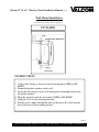
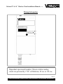
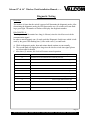
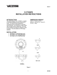
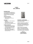
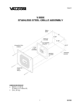
Valcom 12” & 16” Wireless Clock Installation Manual (Rev 1.02) Table of Contents MOUNTING Wall Mount Installation………………………………………………………………… Page 2 Double Mount Installation……………………………………………………………… Page 3 WIRING INFORMATION Wiring Information……………………………………………………………………... Page 4 OPERATION Operational Instructions………………………………………………………………… Pages 5 - 6 FREQUENTLY ASKED QUESTIONS Frequently Asked Questions…………………………………………………………… Page 7 TROUBLESHOOTING Troubleshooting……………………….……………………………………………… Page 8 DIAGNOSTIC TESTING Diagnostic Tests Procedures…………………………………………………………… Pages 9 - 11 FCC INFORMATION FCC Information……………………………………………………………………….. Page 12 For clocks with date codes beginning December 2009 This product is UL and cUL listed Page 1 Valcom 5614 Hollins Road Roanoke, VA 24019 Phone: (540) 563-2000 Fax: (540) 362-9800 www.valcom.com Valcom 12” & 16” Wireless Clock Installation Manual (Rev 1.02) Wall Mount Installation 24 Volt/110 volt options shown in diagram 12” CLOCK INSTRUCTIONS 1. Connect the wiring as shown on the wiring diagram (110V or 24V ONLY). 2. Mount both plastic anchors in the wall. 3. Insert the sheet metal screws (#10) through the mounting bracket into the plastic anchors. 4. Plug the connector into the movement (110V or 24V ONLY). 5. Hang the clock on the mounting bracket. 6. Put the screw (4mm) through the hole on the top of the clock into the hole at the top of the mounting bracket. Page 2 Valcom 5614 Hollins Road Roanoke, VA 24019 Phone: (540) 563-2000 Fax: (540) 362-9800 www.valcom.com Valcom 12” & 16” Wireless Clock Installation Manual (Rev 1.02) Double Mount Installation INSTRUCTIONS 1. Screw the mounting bracket to the double gang box using four (4) inner holes on mounting bracket, or mount the mounting bracket directly to the wall or ceiling using the four (4) outer holes. 2. Insert the wires through the mounting bracket (110V or 24V ONLY). 3. Route the wires through the clock hanging rod. 4. Secure hanging rod to mounting bracket with screws supplied, and place cover over connection. 5. Connect the wiring as shown on the wiring diagrams. 6. Plug the connectors into the movements (110V or 24V ONLY). 7. Place the clocks on the double mount housing and tighten the screws to secure clocks as shown above. Page 3 Valcom 5614 Hollins Road Roanoke, VA 24019 Phone: (540) 563-2000 Fax: (540) 362-9800 www.valcom.com Valcom 12” & 16” Wireless Clock Installation Manual (Rev 1.02) Wiring Information ————————————— ————————————— ————————————— Sapling WIRELESS “WHERE TIMING AND TECHNOLOGY MEET” FCC ID R73AMR001 Diagnostic Switch Diagnostic LED Transmit/Receive Dependent upon model number, Valcom wireless analog clocks are powered by 2 “D” cell batteries, 24 vac or 110 vac. Page 4 Valcom 5614 Hollins Road Roanoke, VA 24019 Phone: (540) 563-2000 Fax: (540) 362-9800 www.valcom.com Valcom 12” & 16” Wireless Clock Installation Manual (Rev 1.02) Operational Instructions IMPORTANT: We highly recommend installing the main transceiver (V-WMCA) before the installation of the Valcom Wireless analog clocks. In order to install the clock, simply remove the battery cover, and install two (2) D cell batteries (recommended battery type: Duracell® PROCELL®). After installation of the batteries, replace the battery cover and the clock should start correcting within five (5) minutes. Normal Mode/Economy Mode The Valcom Wireless Analog Series clocks have two (2) different modes in which they will operate. Normal mode allows the clock to transmit/receive every two (2) hours. This mode will allow the clock to have a 5 year battery life (provided good reception). Economical mode allows the clock to transmit/receive every four (4) hours. This mode will allow the clock to have a 8 year battery life (provided good reception). Normal mode is defaulted when shipped from the factory. To toggle this mode, push and release the Diagnostic Switch and the Transmit/Receive switch simultaneously. If 5 year mode is selected, the LED will be solid RED for one minute and the second hand will go to 5 (25 seconds). If 8 year mode is selected, the LED will be solid GREEN for one minute and the second hand will go to 8 (40 seconds). IMPORTANT: If a clock is being added to an existing system (existing clocks date coded prior to December 2009), it must be in normal mode. There are four (4) ways to install Valcom’s Analog Wireless Clock system. The user can choose any of the combinations listed below, or any combination of the three (3). Option #1: There is a main high powered transceiver in the building (V-WMCA) and repeaters (VWMCRA) as needed to cover the entire premise. In this option, the system does not depend on the slave clocks for transmission. Option #2: There is at least one (1) high powered transceiver (V-WMCA) in the building and in order to cover the entire premise, the battery-operated clocks are used as transceivers/repeaters. Option #3: There is at least one (1) high powered transceiver (V-WMCA) in the building and in order to cover the entire premise, the power (24V or 110V) operated clocks are used as transceivers/repeaters. Option #4: There are multiple transmitters that will cover the entire building or campus. Page 5 Valcom 5614 Hollins Road Roanoke, VA 24019 Phone: (540) 563-2000 Fax: (540) 362-9800 www.valcom.com Valcom 12” & 16” Wireless Clock Installation Manual (Rev 1.02) Operational Instructions Initial Setup 1. All wireless clock systems require at least one master transmitter. This may be a V-WMCA Wireless Master Clock, a V-GPS-TX Wireless Master Clock with GPS or a V-WMCRA Wireless Repeater (configured as a transmitter) that is connected to an appropriate Valcom system. 2. The master transmitter should be installed and operational prior to the installation of any wireless clocks. The preferred location for the master transmitter is typically in a central location that will minimize the number of obstructions (walls, etc) between the master transmitter and the wireless clocks. 3. Clocks should be installed concentrically from the location of the master transmitter. 4. Once a clock is installed and powered (either by installing the batteries or connection to 24V (ac or dc) or 110V 60 Hz ac) it should correct within 5 minutes. If the clock (clock “A” for discussion) does not correct within 5 minutes, press the Transmit/Receive button once on the closest clock that has corrected within the past 12 hours (clock “B” for discussion). The second hand of clock “B” will move to “8” indicating that it is locked in the transmit mode. Next, press the Transmit/Receive button on clock “A” twice. The second hand of clock “B” will move to “4” indicating that it is locked in the receive mode. If clock “A” still does not correct, there is too much distance between clocks. Valcom recommends a maximum clocks separation of 60 feet. Clocks that have been forced into transmit or receive will automatically resume normal operation within 10 minutes. Notes: Refer to the diagnostics section for useful information. Additional master transmitters or V-WMCRA Wireless Repeaters may be added as necessary and/or to propagate correction signal between buildings. The coverage of the master transmitter will vary based upon building construction. This is typically not important as each wireless clock acts as a repeater. Upon application of power, if correction signal is received, the clock will briefly enter diagnostic 2 and the second hand’s landing position will indicate signal strength. Page 6 Valcom 5614 Hollins Road Roanoke, VA 24019 Phone: (540) 563-2000 Fax: (540) 362-9800 www.valcom.com Valcom 12” & 16” Wireless Clock Installation Manual (Rev 1.02) Frequently Asked Questions What battery size do I use for the wireless clock? The batteries required are two (2) “D” cell batteries. The recommended battery type is “Duracell®: Procell® [D] size”. Will the clock cause interference with any of my other wireless devices? No, the Valcom analog wireless clock works on 915 - 928 MHz frequency-hopping technology. The clock switches frequencies automatically when the receiver and transceiver is open, thus interference is avoided. Is there any advantage to a powered clock system as opposed to a battery operated system, assuming a single transceiver is in the building (V-WMCA)? The powered wireless clock receives and transmits every minute and in locations where the signal is marginal, the likelihood of receiving a signal increases because of the frequent transmission rate. What is the advantage of having multiple transceivers V-WMCA on a powered clock system? Assuming the distances between the clocks is sufficient to receive the signal with an analog clock, there is no advantage of multiple transceivers on a powered system. How long does it take for the clock to receive a signal? Upon power up of the clock, the receiver will be turned on for a half hour until the signal is acquired. If the user wishes to manually look for the signal, press the Transmit/Receive switch twice on the movement. Can the clocks be set manually to display the correct time at installation (as a temporary measure until the master clock is installed)? Valcom wireless clocks can NOT be set manually. Page 7 Valcom 5614 Hollins Road Roanoke, VA 24019 Phone: (540) 563-2000 Fax: (540) 362-9800 www.valcom.com Valcom 12” & 16” Wireless Clock Installation Manual (Rev 1.02) Troubleshooting What happens if I power up the clock and the clock is not moving? The clock should move at normal speed upon power up. If it does not move at normal speed, check the battery and make sure the clock receives power. Also, be sure to remove the pin prior to starting up the clock. What happens if the clock does not receive the signal? Take the clock within close proximity to the transceiver and power up the clock. If the clock is batteryoperated, remove the battery and put the battery back in again. Also, press the Transmit/Receive switch once on the clock closest to the clock that is working. The second hand will go to the forty (40) second location notifying the user that the clock is transmitting the signal. Then go to the clock that isn’t working and press the Transmit/Receive switch twice. The second hand will go to the twenty (20) second location notifying the user it is looking for the signal. This should get the signal to the clock. If the clock does not correct, call Valcom technical support. What happens if the clock shows the wrong time? Move the clock to Diagnostic #1 in order to find the last time that it received the signal. Perform a Diagnostic #3 to check the gears for the clock. How do you know if the clock receives a good signal? Perform Diagnostic #2. See page 10 for detailed instructions. I have a location with a marginal signal. What should I do? a. Try to install the transceiver in a nearby area. b. If budget is an issue, install one (1) powered clock. What can I do if I have a clock in a location where the distance is too far away from the last clock? Install a repeater, part number V-WMCRA, to give additional distance to the clock system. Page 8 Valcom 5614 Hollins Road Roanoke, VA 24019 Phone: (540) 563-2000 Fax: (540) 362-9800 www.valcom.com Valcom 12” & 16” Wireless Clock Installation Manual (Rev 1.02) Diagnostic Testing Overview The number of times that the switch is pressed will determine the diagnostic mode. After determining the diagnostic mode, the LED between the two (2) switches will start flashing a green light. The number of flashes will display the diagnostic number. DIAGNOSTIC #1 This diagnostic will determine how long (# of hours) since the clock last received the communication signal. In order to enter diagnostic one (1) mode, push the Diagnostic Switch once which is indicated by the green LED flashing one (1) time with a one (1) second break. A. While in diagnostic modes, hour and minute hands continue to run normally. B. The second hand will display how long since the clock received time signal (please see below table for details) C. After three (3) minutes, the clock will resume normal operation. Second Hand Position 12 Time Since Clock Last Received a Communication Signal Clock has received communication within the past hour 1 “ “ “ between one and two hours ago 2 “ “ “ between two and three hours ago 3 “ “ “ between three and four hours ago 4 “ “ “ between four and five hours ago 5 “ “ “ between five and six hours ago 6 “ “ “ between six and seven hours ago 7 “ “ “ between seven and eight hours ago 8 “ “ “ between eight and nine hours ago 9 “ “ “ between nine and ten hours ago 10 “ “ “ between ten and eleven hours ago 11 “ “ “ more than eleven hours ago Page 9 Valcom 5614 Hollins Road Roanoke, VA 24019 Phone: (540) 563-2000 Fax: (540) 362-9800 www.valcom.com Valcom 12” & 16” Wireless Clock Installation Manual (Rev 1.02) Diagnostic Testing DIAGNOSTIC #2 This diagnostic will determine the quality of the time signal. In order to enter Diagnostic #2 mode, push the Diagnostic Switch twice which is indicated by the green LED flashing twice with a one (1) second break. A. While in diagnostic modes, hour and minute hands continue to run normally. B. The second hand will display the quality of the time signal. (The signal percentage is displayed on the dial of the clock. It goes from 1 – 10, with 1 being the best signal strength and 10 being the least signal strength. C. After three (3) minutes, the clock will resume normal operation. DIAGNOSTIC #3 This diagnostic will test the mechanical portion and some of the electronic components of the clock. In order to enter Diagnostic #3 mode, push the Diagnostic Switch three (3) times which is indicated by the green LED flashing three (3) times with a one (1) second break. Upon completion of Diagnostic 3, if the Diagnostic LED flashes red, the clock requires repair. Please contact Valcom Technical Support. Page 10 Valcom 5614 Hollins Road Roanoke, VA 24019 Phone: (540) 563-2000 Fax: (540) 362-9800 www.valcom.com Valcom 12” & 16” Wireless Clock Installation Manual (Rev 1.02) Diagnostic Testing DIAGNOSTIC #4 This diagnostic will test the battery level of the clock. In order to enter Diagnostic #4 mode, push the Diagnostic Switch four (4) times which is indicated by the LED flashing four times with a one (1) second break. The second hand will display the battery level by stopping one of the numbers on the clock’s face. For example: If the second hand lands on 2, the battery level 2.2V. If the second hand lands on 5, the battery level is 2.5V. If the second hand lands on 9, the battery level is 2.9V. If the second hand lands on 10, the battery level is 3V. If the second hand lands on 11, the battery level is more than 3V. Page 11 Valcom 5614 Hollins Road Roanoke, VA 24019 Phone: (540) 563-2000 Fax: (540) 362-9800 www.valcom.com Valcom 12” & 16” Wireless Clock Installation Manual (Rev 1.02) FCC Wants You to Know This equipment has been tested and found to comply with the limits for a Class B digital device, pursuant to Part 15 of the FCC rules. These limits are designed to provide reasonable protection against harmful interference in a commercial installation. This equipment generates, uses and can radiate radio frequency energy and, if not installed and used in accordance with the instructions, may cause harmful interference to radio communications. However, there is no guarantee that interference will not occur in a particular installation. If this equipment does cause harmful interference to radio or television reception, which can be determined by turning the equipment off and on, the user is encouraged to try to correct the interference by one or more of the following measures: a) Reorient or relocate the receiving antenna. b) Increase the separation between the equipment and receiver. c) Connect the equipment to an outlet on a circuit different from which the receiver is connected. d) Consult the dealer or an experienced radio/TV technician. FCC WARNING Modifications not expressly approved by the manufacturer could void the user authority to operate the equipment under FCC Rules. Note: For precautionary measures, FCC recommends a distance of 10cm from the clock to constant human physical exposure. Page 12 Valcom 5614 Hollins Road Roanoke, VA 24019 Phone: (540) 563-2000 Fax: (540) 362-9800 www.valcom.com