1
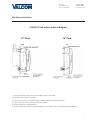
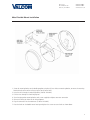
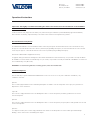
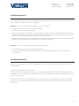
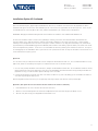
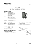
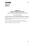
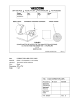
Installation Manual V1.03
V-AW12A / V-AW16A Wireless Clock
Valcom, Inc.
5614 Hollins Road
Roanoke, VA 24019
540-563-2000 P.
540-362-9800 F.
www.valcom.com
Valcom, Inc.
5614 Hollins Road
Roanoke, VA 24019
540-563-2000 P.
540-362-9800 F.
www.valcom.com
SAL-2 Series Wireless Clock
Table of Contents
Table of Contents—2
Wall Mount Installation —3
Metal Double Mount Installation —4
Plastic Double Mount Installation —5
Plastic Double Mount Installation—6
Plastic Double Mount Installation—7
Wiring Information —8
Operational Instructions—9
Installation Option #1—10
Installation Option #2—10
Installation Option #2 Continued—11
Installation Option #3—12
Installation Option #4—12
Frequently Asked Questions—13
Troubleshooting—14
Overview - Diagnostic —15
Diagnostic #1—15
Diagnostic #2—16
Diagnostic #3—16
Diagnostic #4—17
FCC Wants You to Know—18
*manuals may change without prior notice
2
Valcom, Inc.
5614 Hollins Road
Roanoke, VA 24019
540-563-2000 P.
540-362-9800 F.
www.valcom.com
Wall Mount Installation
24 Volt/110 volt options shown in diagrams
12” Clock
16” Clock
1. Connect the wiring as shown on the wiring diagram (110V or 24V ONLY).
2. Mount both plastic anchors in the wall.
3. Insert the sheet metal screws (#10) through the mounting bracket into the plastic anchors.
4. Plug the connector into the movement (110V or 24V ONLY).
5. Hang the clock on the mounting bracket.
6. Put the screw (4mm) through the hole on the top of the clock into the hole at the top of the mounting bracket.
3
Valcom, Inc.
5614 Hollins Road
Roanoke, VA 24019
540-563-2000 P.
540-362-9800 F.
www.valcom.com
Metal Double Mount Installation
1. Screw the mounting bracket to the double gang box using four (4) inner holes on mounting bracket, or mount the mounting
bracket directly to the wall or ceiling using the four (4) outer holes.
2. Insert the wires through the mounting bracket (110V or 24V ONLY).
3. Fish the wires through the clock hanging rod.
4. Secure hanging rod to mounting bracket with screws supplied, and place cover over connection.
5. Connect the wiring as shown on the wiring diagrams.
6. Plug the connectors into the movements (110V or 24V ONLY).
7. Place the clocks on the double mount housing and tighten the screws to secure clocks as shown above.
4
Valcom, Inc.
5614 Hollins Road
Roanoke, VA 24019
540-563-2000 P.
540-362-9800 F.
www.valcom.com
Plastic Double Mount Installation
q
Ethernet
Bracket
e
y
e
y
t
r
y
w
y
5
Valcom, Inc.
5614 Hollins Road
Roanoke, VA 24019
540-563-2000 P.
540-362-9800 F.
www.valcom.com
Plastic Double Mount Installation
*For metal mounting bracket: Use anchor that can support 50 lbs with a maximum screw size of 10/1.5”
q Install metal mounting bracket - First, remove the metal mounting bracket from the inside of the double mount base by unscrewing
the two (2) 6-32 x 1/2” screws located on the underside of the base (save these screws for step #3). Next, screw the metal mounting
bracket to the wall or ceiling in which the clocks are being installed. To mount to the switch box, screw the four (4) 6-32 x 1” screws
supplied in the assembly kit through the inner four holes of the metal mounting bracket to the wall or ceiling. Use the outer four holes
to mount anchors to the wall or ceiling (both anchors and screws for anchors not supplied in kit). For IP clocks, if using an Ethernet
bracket (*as shown in the diagram) use the two (2) 6-32 x 1/4” included in the assembly kit to mount the Ethernet bracket to the metal
mounting bracket (Ethernet bracket not supplied in assembly kit).
Note: if using a plastic switch box, a ground wire must be routed through the switch box and into one (1) of the four (4) metal mounting bracket screws in order to provide ground to the metal mounting bracket.
Note: the metal mounting bracket MUST be secured by both the screws going to the switch box AND the anchors going into the wall.
w Feed wiring through base and pole - Take the wiring coming from the switch box and begin to feed it through the center of the
base of the mounting assembly until it emerges from the hole in the center of the clock adaptor. Make sure there is roughly 1.5’ - 2’
of wiring coming from the switch box. Perform this task for both clocks. If installing IP clocks, run bare Ethernet wire without an RJ45
connector and install the connector after it has been routed through the clock if possible (this will be much easier than running the
wire with the connector on). If not possible, make sure that there is no boot present on the connector to run the wire through the
assembly. If you are using an Ethernet bracket with the installation of IP clocks, the assembly of the clocks in steps 4 through 6 can be
accomplished before mounting the assembly to the wall in step 3 - making the overall installation more simple.
Note: if the installer wishes to adjust the distance between the clock adaptor and the base of the double mount, this can be accomplished by removing the adaptors from the double mount pole and choosing a
different hole on the double mount pole to route the wiring through before mounting to the wall.
e
Snap and screw base to metal mounting bracket - Snap the base to the metal mounting bracket by first making contact with the
lip in the upper side of the base and the metal mounting bracket. When the base has been snapped onto the bracket, take the two (2)
6-32 x 1/2” pan head screws that originally came installed on the base of the mounting assembly and screw them back into the two
holes on the underside of the base to secure the base to the metal mounting bracket.
r
Connect switch box wires to clock harness - Take the wiring harness supplied with the clock and make all necessary connections
between the wiring harness and the switch box wires using wire nuts. Perform this task for both clocks.
*instructions continued on next page
6
Valcom, Inc.
5614 Hollins Road
Roanoke, VA 24019
540-563-2000 P.
540-362-9800 F.
www.valcom.com
Plastic Double Mount Installation
t
Plug and secure wiring to clock - Loosen and slip excess wiring through provided wire clamp (comes attached to each clock adaptor) and
tighten the clamp. After securing excess wiring, plug the jack at the end of the wiring into the appropriate jack on the back of the clock. If
using IP clocks, wiring will not be supplied with the clocks - the installer will be responsible for supplying all Ethernet wiring.
y
Attach and screw clocks to adaptors - Find all four (4) tabs located on each adaptor. Snap the clock onto the adaptor, making sure all
four (4) tabs on the adaptor are secured to the clock (if installing battery powered clocks, make sure batteries are installed at this point).
After securing the clock to the adaptor with the tabs, the clock should be able to rotate 5 degrees left and right. Rotate to align the clocks
with the ceiling or wall. Secure its position by using the four (4) 6-19 x 7/16” screws that come attached to the clock adaptor from the factory
and screw them into the four (4) tabs on the adaptor.
7
Valcom, Inc.
5614 Hollins Road
Roanoke, VA 24019
540-563-2000 P.
540-362-9800 F.
www.valcom.com
Wiring Information
The V-AW12A and V-AW16A wireless clocks can be powered by 2 “D” cell batteries, 24 volts AC, 110 volts AC, or 220 volts AC.
8
Valcom, Inc.
5614 Hollins Road
Roanoke, VA 24019
540-563-2000 P.
540-362-9800 F.
www.valcom.com
Operational Instructions
Important: We highly recommend installing the main transceiver before the installation of the V-AW12A
and V-AW16A clocks.
In order to install the clock, simply remove the battery cover, and install two (2) D cell batteries (recommended battery type: Duracell PROCELL).
After installation of the battery, replace the battery cover and the clock should start correcting within five (5) minutes.
Normal Mode/Economy Mode
The V-AW12A and V-AW16A clocks have two different modes in which they will operate. Normal mode allows the clock to transmit/receive every
two (2) hours. This mode will allow the clock to have a 5 year battery life (provided good reception). Economical mode allows the clock to transmit/
receive every four (4) hours. This mode will allow the clock to have a 8 year battery life (provided good reception).
Normal mode is defaulted when shipped from the factory.
To toggle this mode, push and release the Diagnostic Switch and the Transmit/Receive switch simultaneously. If 5 year mode is selected, the LED will
be solid RED for one minute and the second hand will go to 5 (25 seconds). If 8 year mode is selected, the LED will be solid GREEN for one minute and
the second hand will go to 8 (40 seconds).
IMPORTANT: If a clock is being added to an existing system, it must be in normal mode.
Installation Options
There are three ways to operate V-AW12A and V-AW16A Wireless Clocks. The user can choose any of the combinations listed below, or any
combination of the three.
Option #1:
There is a main high powered transceiver in the building and repeaters as needed to cover the entire premise. In this option, the system does not
depend on the clock for transmission.
Option #2:
There is at least 1 high powered transceiver in the building and in order to cover the entire premise, the battery operated clocks are used as
transceivers/repeaters.
Option #3:
There is at least 1 high powered transceiver in the building and in order to cover the entire premise, the power (24V or 110V) operated clocks are used
as transceivers/repeaters.
Option #4:
In a campus-environment, there is either 1 high powered transceiver and the clocks and repeaters are used to send the signal from building to
building, or there is a transceiver in each building in the campus.
9
Valcom, Inc.
5614 Hollins Road
Roanoke, VA 24019
540-563-2000 P.
540-362-9800 F.
www.valcom.com
Installation Option #1
There is a main high powered transceiver in the building and high powered transceivers or repeaters as needed to cover the entire premise. In this
option, the system does not depend on the clock for transmission.
OPTION 1A: Transceivers or repeaters are synchronized wirelessly to the main transceiver.
1. Place the main transceiver in a central location (hallway recommended).
2. Pick the location of the second transceiver or repeater.
3. Place the transceiver/repeater in a location where the signal is available from the main transceiver. In order to verify that the transceiver is receiving a signal from the main transceiver, power up the transceiver and within five minutes, it shall show the main transceiver time. If the transceiver
did not correct to the main transceiver time, choose a different location for the transceiver.
4. Repeat the above mentioned steps with the corresponding transceivers or repeaters. Please note that the corresponding transceivers or repeaters
can receive a signal from another transceiver or repeater, and not only from the main transceiver.
OPTION 1B: Transceivers or repeaters are synchronized via wire to the main transceiver.
1.
Place the main transceiver in a central location (hallway recommended).
2.
Run two conductive wires between the main transceiver and the corresponding transceivers or repeaters in order to transmit the time
between the units.
Installation Option #2
There is at least one (1) high powered transceiver in the building and in order to cover the entire premise, the battery operated clocks are used as
transceivers/repeaters.
Clock Operational Overview (Battery Operation Version)
In order to reserve battery consumption, the receiver of the clock is enabled for ten (10) minutes upon power up. During normal operation, the
clock enables its transceiver every two hours (in normal mode). The clock also has the capability to transmit/receive during normal operation every
four hours (in economy mode).
There is a manual option, by pressing the Transmit/Receive switch twice to enable the receiver for ten (10) minutes in order to receive the time
signal. In this case, the second hand will move to the twenty (20) second location until the signal is received, and then the clock will resume
normal operation.
10
Valcom, Inc.
5614 Hollins Road
Roanoke, VA 24019
540-563-2000 P.
540-362-9800 F.
www.valcom.com
Installation Option #2 Continued
There is another manual option, by pressing the Transmit/Receive switch once, to enable the clock transceiver for ten (10) minutes in order to
transmit the time signal. The transceiver can be enabled only if the clock receives a time signal within the last twelve (12) hours. In this case, the
second hand will move to the forty (40) second location, and after ten (10) minutes, the clock will resume normal operation.
IMPORTANT: We highly recommend installing the main transceiver before the installation of the V-AW12A and V-AW16A clocks.
The transceiver should be located in a central location, preferably in a hallway, so that there are a minimum number of walls between the
transceiver and the clocks. After the installation of the transceiver, begin installing the clocks nearest to the transceiver; continue installing
remaining clocks working from the transceiver as the central point. In order to install the clock, simply remove the battery cover, and install two
(2) D cell batteries (recommended battery type: Duracell PROCELL). After installation of the battery, replace the battery cover and the clock should
start correcting within five (5) minutes. If correction is not received within the first five (5) minutes, please follow these instructions. The steps on
the following pages are recommended in order to synchronize the clock system for the first time. The steps are critical due to the fact that the clock
receives and transmits every two (2) hours.
Option 2A:
Go to the nearest clock (clock #1) that has received correction and press the Transmit/Receive switch once. The second hand should move to forty
(40) seconds, and the clock should stop running. This is an indication that the clock is in transmission mode.
1. Go to the clock (clock #2) that did not receive transmission, and press the Transmit/Receive switch twice. The second hand should move to twenty
(20) seconds until the clock receives signal from clock #1. Then clock #2 will display the master time within a five (5) minute period. Within ten
(10) minutes of Step 1, clock #1 will resume operation and will go to the correct time.
2. Continue with the same process with all of the other clocks. Please note while one (1) clock is transmitting, you are not limited to the number of
clocks that can go through the Step 2 process.
When moving further from the transceiver, you can repeat Step 1 and Step 2 using the clock that most recently received signal.
Option 2B: (This option does not test that the distances between the clocks are sufficient)
1.
Install the batteries in the clocks in the same area as the main transceiver.
2.
After the clock has received signal from the transceiver and adjusted to the main transceiver time, place the battery cover on.
3.
Take each clock, while running, to its designated area and install the clock.
11
Valcom, Inc.
5614 Hollins Road
Roanoke, VA 24019
540-563-2000 P.
540-362-9800 F.
www.valcom.com
Installation Option #3
There is at least one high powered transceiver in the building in order to cover the entire premises. The power (24V or 110V) operated clocks are
used as transceivers/repeaters.
Clock Operational Overview (Power Operation 24V or 110V Version)
The clock enables its receiver for 10 minutes upon power up and during normal operation every minute. The clock also has the capability to
transmit every minute during normal operation or during power up once data is received.
We highly recommend installing the main transceiver before the installation of the V-AW12A and V-AW16A clocks. The transceiver should be
located in a central location preferably in a hallway so that there are a minimum number of walls between the transceiver and the clock. After
the installation of the transceiver, begin installing the clocks nearest to the transceiver; continue installing remaining clocks working from the
transceiver as the central point. In order to install the clock, simply connect power to the clock using our pigtail connector.
Installation Option #4
This option allows the user to use multiple transmitters on a campus-like environment.
If a situation arises where the need is to have multiple buildings be synchronized with the wireless system, there are two options.
Option 4a:
There is one transmitter and the clocks or repeaters send the signal to the other buildings.
This option is when the transmitter or the clocks are in range to the repeater in the other buildings. If the transmitter reaches the repeaters or
clocks in the other building(s), the clocks will correct off of the repeater’s transmission of the signal.
Option 4b:
There is a transmitter in each building.
This option is used when the transmitter or the clocks will not reach the repeaters or clocks in the other building(s). In this case, using multiple
transmitters for each building would be the easiest set-up. By connecting the transmitters to the Internet and receive the time from the Internet,
each clock will be identically synchronized.
12
Valcom, Inc.
5614 Hollins Road
Roanoke, VA 24019
540-563-2000 P.
540-362-9800 F.
www.valcom.com
Support
Frequently Asked Questions
What battery size do I use for the wireless clock?
The batteries required are two (2) “D” cell battery. The recommended battery type is “Duracell: Procell [D] size”.
Will the clock cause interference with any of my other wireless devices?
No, the V-AW12A and V-AW16A wireless clock works on 915 - 928 MHz frequency-hopping technology. The clock switches frequencies
automatically when the receiver and transceiver is open, thus interference is avoided.
Is there any advantage to a powered clock system as opposed to a battery operated system, assuming a single transceiver is in the
building?
The powered wireless clock receives and transmits every minute and in locations where the signal is marginal, the likelihood of receiving a signal
increases because of the frequent transmission rate.
What is the advantage of having multiple transceivers on a powered clock system?
Assuming the distances between the clocks is sufficient to receive the signal with an analog clock, there is no advantage of multiple transceivers
on a powered system.
How long does it take for the clock to receive a signal?
Upon power up of the clock, the receiver will be turned on for a ten (10) minutes until the signal is acquired. If the user wishes to manually look
for the signal, press the Transmit/Receive switch twice on the movement.
Can the clocks be set manually to display the correct time at installation (as a temporary measure until the master clock is installed)?
V-AW12A and V-AW16A clocks can NOT be set manually.
13
Valcom, Inc.
5614 Hollins Road
Roanoke, VA 24019
540-563-2000 P.
540-362-9800 F.
www.valcom.com
Support
Troubleshooting
What happens if I power up the clock and the clock is not moving?
The clock should move at normal speed upon power up. If it does not move at normal speed, check the battery and make sure the clock receives
power. Also, be sure to remove the pin prior to starting up the clock. If the clocks are 24 volt or 110 volt, please verify the wiring on page 7 of
this manual.
What happens if the clock does not receive the signal?
Take the clock within close proximity to the transceiver and power up the clock. If the clock is battery operated, remove the battery and put the
battery back in again.
Also, press the Transmit/Receive switch once on the clock closest to the clock that isn’t working. The second hand will go to 8 notifying the user
that the clock is transmitting the signal. Then go to the clock that isn’t working and press the Transmit/Receive switch twice. The second hand will
go to 4 notifying the user it is looking for the signal. This should get the signal to the clock.
If the clock does not correct, call Valcom technical support.
What happens if the clock shows the wrong time?
Move the clock to Diagnostic #1 in order to find the last time that it received the signal.
Perform a Diagnostic #3 to check the gears for the clock.
How do you know if the clock receives a good signal?
Perform Diagnostic #2. See page 16 for detailed instructions.
I have a location with a marginal signal. What should I do?
a. Try to install the transceiver in a nearby area.
b. If budget is an issue, install one (1) powered clock.
What can I do if I have a clock in a location where the distance is too far away from the last clock?
Install a repeater to give additional distance to the clock system.
14
Valcom, Inc.
5614 Hollins Road
Roanoke, VA 24019
540-563-2000 P.
540-362-9800 F.
www.valcom.com
Diagnostic Testing
Overview - Diagnostic
The number of times that the switch is pressed will determine the diagnostic mode. After determining the diagnostic mode, the LED between the
two (2) switches will start flashing a green light. The number of flashes will display the diagnostic number.
Diagnostic #1
This diagnostic will determine how long (# of hours) since the clock last received the communication signal.
In order to enter diagnostic #1 mode, push the Diagnostic Switch once which is indicated by the green LED flashing one time with a 3 second
break.
A. While in diagnostic modes, hour and minute hands continue to run normally.
B. The second hand will display how long since the clock received time signal (please see below table for details)
C. After three (3) minutes, the clock will resume normal operation.
Second Hand Position
Time Since Clock Last Received a Communication Signal
12
Clock has received communication in the past hour
1
Clock has received communication between one and two hours ago
2
Clock has received communication between two and three hours ago
3
Clock has received communication between three and four hours ago
4
Clock has received communication between four and five hours ago
5
Clock has received communication between five and six hours ago
6
Clock has received communication between six and seven hours ago
7
Clock has received communication between seven and eight hours ago
8
Clock has received communication between eight and nine hours ago
9
Clock has received communication between nine and ten hours ago
10
Clock has received communication between ten and eleven hours ago
11
Clock has received communication over eleven hours ago
15
Valcom, Inc.
5614 Hollins Road
Roanoke, VA 24019
540-563-2000 P.
540-362-9800 F.
www.valcom.com
Diagnostic Testing
Diagnostic #2
This diagnostic will determine the quality of the time signal.
In order to enter Diagnostic #2 mode, push the Diagnostic Switch twice which is indicated by the green LED flashing twice with a three (3) second
break.
A. While in diagnostic modes, hour and minute hands continue to run normally.
B. The second hand will display the quality of the time signal. (The signal percentage is displayed on the dial of the clock. It goes from 1 – 10, with 1 being the best signal strength and 10 being the least signal strength.
C. After three (3) minutes, the clock will resume normal operation.
Diagnostic #3
This diagnostic will test the mechanical portion and some of the electronic components of the clock.
In order to enter Diagnostic #3 mode, push the Diagnostic Switch three times which is indicated by the green LED flashing three (3) times with a
three (3) second break.
If an error occurs, the clock will flash the red LED to signal the error code number (please see table below) While in Diagnostic #3, the clock will
perform the following steps:
A. Clock moves second hand to 00.
B. Clock moves second hand again to 00, to verify that the hands arrived after
sixty (60) pulses.
C. Clock moves minute and hour hands to the next known position.
D. Clock moves minute and hour hands again to the same known position in order to verify that the hands reach the position after 720 pulses.
E. Clock moves the hour and minute hands to 12:00:00.
F. Test frequency, if battery it shall be D/C, other 60Hz/50Hz.
Number of Red Flashes
Diagnosis of Error Code
1,2
Clock detected problem with second hand. Check hands to see if they are hitting each other. Repeat test.
3,4,5
Clock detected problem with hour/minute hand. Check to see if they are hitting each other. Repeat test.
6
Call tech support.
16
Valcom, Inc.
5614 Hollins Road
Roanoke, VA 24019
540-563-2000 P.
540-362-9800 F.
www.valcom.com
Diagnostic Testing
Diagnostic #4
This diagnostic will test the battery level of the clock.
In order to enter Diagnostic #4 mode, push the Diagnostic Switch four (4) times which is indicated by the LED flashing four times every three
seconds.
The second hand will display the battery level by stopping one of the numbers on the clock’s face.
For example:
•
If the second hand lands on 2, the battery level 2.2V.
•
If the second hand lands on 5, the battery level is 2.5V.
•
If the second hand lands on 9, the battery level is 2.9V.
•
If the second hand lands on 10, the battery level is 3V.
•
If the second hand lands on 11, the battery level is more than 3V.
17
Valcom, Inc.
5614 Hollins Road
Roanoke, VA 24019
540-563-2000 P.
540-362-9800 F.
www.valcom.com
FCC Wants You to Know
This equipment has been tested and found to comply with the limits for a Class B digital device, pursuant to Part 15 of the FCC
rules. These limits are designed to provide reasonable protection against harmful interference in a commercial installation.
This equipment generates, uses and can radiate radio frequency energy and, if not installed and used in accordance with the
instructions, may cause harmful interference to radio communications. However, there is no guarantee that interference will
not occur in a particular installation. If this equipment does cause harmful interference to radio or television reception, which
can be determined by turning the equipment off and on, the user is encouraged to try to correct the interference by one or
more of the following measures:
a) Reorient or relocate the receiving antenna.
b) Increase the separation between the equipment and receiver.
c) Connect the equipment to an outlet on a circuit different from which the receiver is connected.
d) Consult the dealer or an experienced radio/TV technician.
FCC WARNING
Modifications not expressly approved by the manufacturer could void the user authority to
operate the equipment under FCC Rules.
Note: For precautionary measures, FCC recommends a distance of 10cm from the clock to constant human physical exposure.
18