1
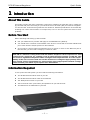
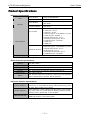
SAMSUNG
DCS-VIP
INTERNET
KEYPHONE
QUICK GUIDE
TO
INSTALLATION &
CONFIGURATION
Publication Information
Samsung Telecoms reserves the right without prior notice to revise information in
this publication for any reason.
Samsung Telecoms also reserves the right without prior notice to make changes in
design or components of equipment as engineering and manufacturing may warrant.
Disclaimer
Samsung Telecoms is not responsible for errors or problems arising from customers
not installing, programming or operating their Samsung systems as described in this
manual.
Copyright 2002
Samsung Telecoms (U.K.) Limited
All rights reserved. No part of this manual may be reproduced in any form or by any
means – graphic, electronic or mechanical, including recording, taping, photocopy or
information retrieval system – without express written permission of the publisher of
this material.
Part No.: 16106
Version 3.0
EU Declaration of Conformity (RTTE)
Samsung Electronics Co., Ltd.
259 Gongdan-Dong, Gumi-City Kyungbuk, Korea, 730-030
(factory name, address)
declare under our sole responsibility that the product
Digital Keyphone System "DCS VIP"
to which this declaration relates is in conformity with
RTTE Directive 1999/5/EC ( Annex II )
Low Voltage Directive 73/23/EEC
EMC Directive 89/336/EEC:92/31/EEC
By application of the following standards
EN55022 : 1998 Inc A1: 2000*
.........................................................................................
EN61000-3-2:1995 Inc. A1/A2:1998
.........................................................................................
EN61000-3-3:1995, EN61000-4-2:1995 Inc. A1:1998, EN61000-4-3:1996 Inc. A1:1998
.........................................................................................
EN61000-4-4:1995, EN61000-4-5:1995, EN61000-4-6:1996, EN61000-4-8:1993
.........................................................................................
EN61000-4-11:1994, AS/NZS3548:1995
.........................................................................................
EN60950 ; 1992+A1+A2+A3+A4+A11
.........................................................................................
.........................................................................................
(Manufacturer)
Samsung Electronics Co., Ltd
259, Gongdan-Dong, Gumi-City
Kyungbuk, Korea, 730-030
TE Jang
2001-03-31
.................................................
Tae-eok Jang / General Manager
.................................................................................
(place and date of issue)
(name and signature of authorized person)
(Representative in the EU)
Samsung Electronics Euro QA Lab.
Blackbushe Business Park
Saxony Way, Yateley, Hampshire
GU46 6GG, UK
IS Lee
2001-04-03
.................................................
In-Seop Lee / Manager
...............................................................................
(place and date of issue)
(name and signature of authorized person)
Intended Use
This apparatus provides a number of Samsung proprietary digital extensions, analogue extensions, 10/100 Base-T LAN connections, an integral Router and an integral CTI Telephony
Server. It is intended to connect only to ISDN Basic Rate circuits provided by a public network operator. The apparatus is mains powered.
It is not intended for any other use. Please read the provided user instructions carefully.
DCS-VIP Internet Keyphone
Quick Guide
Contents
1 Introduction .......................................................................................................................1
About This Guide ................................................................................................................... 1
Before You Start ..................................................................................................................... 1
Information Required .............................................................................................................. 1
Product Specifications ............................................................................................................ 2
Environmental Requirements .................................................................................................. 3
2
Installing Your DCS-VIP ................................................................................................4
Grounding the VIP Router ....................................................................................................... 4
Connecting the ISDN Line(s) ................................................................................................... 5
Connecting a PC or Hub ......................................................................................................... 5
Connecting Digital or Analogue Telephones ............................................................................. 6
Connecting the Power Cord .................................................................................................... 6
Connecting an Expansion Unit ................................................................................................ 7
3
Configuring Your DCS-VIP ..........................................................................................8
Switching On the System ........................................................................................................ 8
Clearing the Memory .............................................................................................................. 8
Connecting to the Web Management Screen ........................................................................... 8
Running the Wizard Setup ...................................................................................................... 9
Configuring the Keyphone Functions ........................................................................................ 10
Configuring the Router Functions ............................................................................................ 13
Configuring the VoIP Functions .............................................................................................. 16
Changing the System IP Address .......................................................................................... 19
4
Saving System Configuration Information .......................................................... 20
5
Restoring System Configuration Information ..................................................... 22
Restoring Router Configuration Information from Flash Memory ............................................... 22
Restoring Configuration Information from PC Hard Disk ........................................................... 23
6
DCS-VIP Remote Programming .............................................................................. 25
Assumptions.......................................................................................................................... 25
Remote Programming Procedure on Slave Site ..................................................................... 25
Remote Programming Procedure on Master Site .................................................................... 27
Appendix: Installing & Programming Voice Over IP (VoIP)
on the DCS-VIP .................................................................................................................. 30
—i —
DCS-VIP Internet Keyphone
1
Quick Guide
Introduction
About This Guide
This guide provides the basic information required for installing the DCS-VIP router (called simply the DCS-VIP) and connecting to your Internet Service Provider (ISP) for Internet navigation.
You should refer to the Samsung DCS-VIP User Guide for detailed specifications of the DCS-VIP,
including the names and functions of components, how to use the system and how to solve
problems.
Before You Start
Before installing and setting up the DCS-VIP:
l
Call your ISDN service provider and apply for an ISDN BRI line (ISDN 2).
l
You should have a network card installed in the PC to be connected to the DCS-VIP Ethernet
port. Check that the TCP/IP protocol is also installed.
l
If you want to connect network equipment such as a hub or router to the Ethernet port of
the DCS-VIP, you will need a category-5 crossover cable.
WARNING
DCS-VIP is a network routing device and will make a telephone call in response to a valid
request from a client PC; for example, from an email program running on that PC. This
can result in significant telephone traffic and higher than expected bills. It is the responsibility of the user to ensure that PCs on the network are configured appropriately. Samsung cannot accept responsibility for issues arising from inappropriate network configuration. Contact your dealer if you require more information.
Information Required
To set up the DCS-VIP system you will need the following information.
l
The IP address and subnet mask of your PC
l
The IP address and subnet mask of the DCS-VIP
l
The ISDN phone number of your ISP
l
The Account ID name (host name) and password of your ISP account
l
The DNS Server IP addresses of your ISP
—1—
DCS-VIP Internet Keyphone
Quick Guide
Product Specifications
Hardware Specifications
CPU
Memory
Port Interface
Dimensions
Router Module
Motorola MC68EN360
Keyphone Module
Motorola MC68EN302
16Mb DRAM
Router Module
2Mb Flash
8Mb DRAM
Keyphone Module
2Mb Flash
2 ISDN BRI Interfaces : S/T type
1 VoIP port : RJ-45
Main System
1 SIO port : RJ-45
7 Ethernet ports : 10/100Base-T, RJ-45
1 Ethernet port: 10Base-T
6 Digital Phone ports : RJ-11
4 Analogue Phone ports : RJ-11
1 Expansion port : RS-232C
1 BATT port
1 MOH port
2 ISDN BRI Interfaces : S/T type
8 Ethernet ports : 10/100Base-T, RJ-45
2 Digital Phone ports : RJ-11
Expansion System
4 Hybrid ports : RJ-11
4 Analogue Phone ports : RJ-11
1 Expansion port : RS-232C
426.79(W) x 278.4(D) x 49.9(H) (mm)
Router Software Specifications
IP (Static Routing)
Routing
IPX (SAP, WAN)
WAN Service
PPP, ML-PPP
Management
Security
Compression
Option
SNMP, Web based, Telnet
PAP, CHAP, Caller ID, Callback, Filtering (Access List)
Stac LZS, Predictor
NAT (Network Address Translation), DHCP Server, DHCP Relay
Agent, Bandwidth on demand, Dial on demand
Keyphone Software Specifications
System Features
Attendant Group, Barge-in, Call Waiting, Class Of Service,
Conference, In Group/Out of Group, Least Cost Routing, Music
On Hold, Page, SMDR, Call Transfer
Station Features
Alarm Reminder, Answer Mode, Boss/Secretary, Call Forwarding, Hold, Camp-on, Do Not Disturb, Message Waiting, Redial,
Speaker Phone, Speed Dial, Trunk Callback
Optional Features
CTI, ISDN AOC, ISDN COLP/COLR, ISDN DDI, ISDN MSN,
ISDN Sub-address, Voice Mail System
—2—
DCS-VIP Internet Keyphone
Quick Guide
VoIP Software Specifications
Basic Features
Incoming Call, Outgoing Call, Call Forward, Call Transfer,
Call Wait, Redial
System Features
Set µ/A-Law, Translation Tel No. to IP Address, Web-based
Management
VoIP Features
Trunk Account, IP Conversion Table, Remote Download
Environmental Requirements
l
Input Voltage
: 120-240 VAC (Free Volt)
l
Frequency
: 50–60Hz
l
Power Consumption
: 70 Watts
l
Operating Temperature
: 0°C – 40°C
l
Relative Humidity
: 10% – 90% (Non-condensing)
Caution
When installing the DCS-VIP main router you must ensure a free space of at least
100mm above the unit.
—3—
DCS-VIP Internet Keyphone
2
Quick Guide
Installing Your DCSDCS-VIP
Refer to the following network connection diagram, and then connect each cable to the appropriate port on the rear panel of the DCS-VIP as described.
Internet Service Provider
Internet
ISDN connection box
DCS-VIP router
Power
Power
Ethernet hub
Analogue Phone
Digital Phone
PC
PC
¶
Grounding the VIP Router
The DCS-VIP base unit is provided with a third-wire AC ground through the power cord, which is
adequate for most applications. However, if it is suspected that there is a problem with the
ground provided at the AC outlet, or local codes require a solid earth ground to be connected to
the router, the existing third -wire ground must be disconnected and a new ground connected to
the grounding lug on the rear of the unit (see illustration below). Contact your dealer or Technical Support for advice and read the ‘Warning’ notice b elow.
Failure to provide an adequate ground may cause unpredictable operation or even circuit failure.
Warning
Unplug the power cord from the AC outlet before attempting to connect a new ground.
Hazardous voltage may cause death or injury. Observe extreme caution when working with
AC power.
—4—
DCS-VIP Internet Keyphone
·
Quick Guide
Connecting the ISDN Line(s)
DCS-VIP router
ISDN connection box
ISDN cable
1. Connect the ISDN cable to the port labelled ‘BRI1’ on the rear panel of the DCS-VIP.
2. Connect the other end of the ISDN cable to the ISDN connection box.
3. If a second ISDN line is required, connect the second ISDN cable to the port labelled ‘BRI2’
on the rear panel of the DCS-VIP, and connect the other end to the ISDN connection box.
¸
Connecting a PC or Hub
Connecting a PC
There are eight Ethernet ports on the rear panel of the DCS-VIP. You can connect a PC to each
Ethernet port (a maximum of eight PCs).
1. Connect an Ethernet cable to any of the Ethernet ports on the rear panel of the DCS-VIP.
2. Connect the other end of the Ethernet cable to the connector on your PC.
Connecting a Hub
If you want to set up the network for more users, yo u can extend the number of ports by co nnecting another hub, switch or router.
—5—
DCS-VIP Internet Keyphone
Quick Guide
1. Connect an Ethernet crossover cable (not included) to any of the Ethernet ports on the rear
panel of the DCS-VIP.
2. Connect the other end of the cable to an available port on your Ethernet hub, switch or
router.
¹
Connecting Digital or Analogue Telephones
You can connect a digital telephone to a DLI port on the rear panel of your DCS-VIP, and you
can connect an analogue telephone to an SLI port.
1. Connect the telephone cable to the port labelled DLI or SLI on the rear panel of your DCSVIP.
2. Connect the other end of the telephone cable to an RJ-11 port on your digital or analogue
telephone.
DCS-VIP router
Analogue phone
Digital phone
Note
1. Cables with RJ-11 connectors at each end for use with DCS keyphones are available from your dealer.
2. If a category 5 patch panel is to be used, a suitable RJ-11 to RJ-45 converter cable is required.
3. A single line telephone may require a connector with a ringing capacitor fitted. These are available from
your dealer.
º
Connecting the Power Cord
When all of the cable connections to the DCS-VIP system are done, connect the provided power
cord as follows.
1. Connect the power cord to the power input connector on the rear panel of the DCS-VIP.
2. Connect the other end of the power cord to the electrical outlet.
DCS-VIP router
—6—
DCS-VIP Internet Keyphone
»
Quick Guide
Connecting an Expansion Unit
An optional expansion unit can be connected with the main unit if there are more PCs or telephones to connect to the DCS-VIP than the main unit can handle. The expansion unit provides a
further two ISDN circuits and a further 10 voice ports.
Caution
When installing a DCS-VIP expansion unit, it should be installed BELOW the main
router unit.
Two cables are supplied to connect an expansion unit:
l
A short hub cable which connects an Ethernet port on the rear of the DCS-VIP to an
Ethernet port on the rear of the expansion unit.
l
A power and data cable which connects both units via the multiway expansion connectors.
—7—
DCS-VIP Internet Keyphone
3
Quick Guide
Configuring Your DCSDCS-VIP
After installing the DCS-VIP system, switch it on. Using a PC, run a web browser and connect to
the default system IP address. Run the Wizard Setup on the startup screen of the DCS-VIP to
easily and quickly configure the system. (When configuration is complete, you must save the information in sys tem flash memory and on the PC’s hard disk. This is described in section 4.)
¶
Switching On the System
Switch on the system by pressing the power on/off switch on the rear panel of the DCS-VIP. The
‘Run’ LED lights green and the system performs a start-up routine. When completed, the Run
LED flashes.
DCS-VIP router
·
Clearing the Memory
Using a digital keyset, program MMC 811 (Reset System) to reset and clear the system memory
via the CLEAR MEMORY option (see the Samsung DCS-VIP Internet Keyphone Programming Man ual for details).
¸ Connecting to the Web Management Screen
The factory default IP address of the DCS-VIP is "1.1.1.1". To set up the DCS-VIP system, run
the web browser (Internet Explorer 5.0 or later, or Netscape Navigator 4.5 or later, is recommended) and connect to this default IP address.
1. To reset the IP address, subnet mask and gateway of the PC to be used for setting up the
DCS-VIP system, double click the Network icon in the Windows Control Panel. Set each
of the following properties.
l
IP address : 1.1.1.2
l
Subnet mask : 255.0.0.0
l
Gateway : 1.1.1.1
Note
Ensure that the TCP/IP protocol is installed in the PC.
—8—
DCS-VIP Internet Keyphone
Quick Guide
2. Reboot the system and run the web browser.
3. Make a connection to the DCS-VIP system with IP address "1.1.1.1".
4. Enter the default User Name ‘guest’ and Password ‘samsung’.
The web-based management screen for the DCS-VIP appears.
¹
Running the Wizard Setup
By running the Wizard Setup, you can easily and quickly configure the DCS-VIP system.
—9—
DCS-VIP Internet Keyphone
Quick Guide
Configuring the Keyphone Functions
Click the WIZARD SETUP—>KEYPHONE SETUP option. In the Keyphone Setup Wizard you
can set basic information, such as country of installation, area code, system date, ISDN option,
etc, necessary for using DCS-VIP keyphone functions.
Setup Wizard 1
On this screen, you can set the country where the DCS-VIP is installed (e.g. UK).
Set the country by clicking the dropdown button of the Country parameter. (If you set the
wrong country, the system may not operate normally because system standards between countries are different.) Click the Next button.
Note
If you change the country, the system data is reinitialised with information for the new country.
Setup Wizard 2
On this screen, you can set the area code, system date and system status.
Set the following parameters.
l
Area Code: Enter the code of the area where the DCS-VIP will be installed. (Not used in
UK.)
— 10 —
DCS-VIP Internet Keyphone
Quick Guide
l
System Date: Set the system date and time. The set date and time will be save d in the
system memory.
l
System Status: Displays system status, such as whether the DCS-VIP system is equipped
with the VoIP function, if an expansion unit is connected, and the trunk line type.
Click the Next button.
ISDN
ISDN Option
On this screen, you can set the ISDN switch type and ISDN mode.
Set the following parameters.
l
Switch Type: Select the switch type that is used by the local ISDN service provider.
l
ISDN Mode: Select the mode of the BRI trunk that will be used.
−
Normal: Select the default user to ring for incoming calls.
−
DDI: (P–P protocol) Directly connect an external call to a selected internal user.
−
MSN: (P–MP protocol) Allows the use of different numbers for each BRI channel.
Click the Next button.
Trunk Ring
This screen appears only if you set Normal as the ISDN Mode parameter on the ISDN Option
screen. You can set the station number to ring for an incoming call on each trunk line.
— 11 —
DCS-VIP Internet Keyphone
Quick Guide
In the Day field, set the station telephone number to ring for incoming calls on each trunk. For
example, to set station 208 to ring for calls on trunk 704, click the dropdown button to the right
of Trunk No. 704 and select 208. Then, click the Next button.
DID Digit
This screen appears only if you set DDI as the ISDN Mode parameter on the ISDN Option
screen. You can program a station (or a group) to ring directly from an external incoming telephone call.
Set the following parameters.
l
Incoming digit: Enter the DDI digits to be matched when you want to ring a station directly from the e xternal network.
l
Type: Set the type of the station to ring.
−
STN: Ring a specified station.
−
SGRP: Ring a station group.
−
TGRP: Ring a trunk group.
−
B: When B is selected, the number of digits shown in the “Delete Count” field will be
deleted and the resultant number matched to an extension, station group, etc.
l
Destination: Select the station to ring when you select ‘STN’ in the ‘Type’ parameter.
l
Delete Count: Enter the number of digits to be deleted when you select ‘B’ in the ‘Type’ parameter.
Click the Next button.
MSN Digit
This screen appears only if you set MSN as the ISDN Mode parameter on the ISDN Option
screen. You can make a transfer table to use BRI trunks in the MSN (Multiple Subscriber Number) mode.
— 12 —
DCS-VIP Internet Keyphone
Quick Guide
Set the following parameters.
l
Tel No.: Select the trunk number which will be used in MSN mode.
l
MSN Digit: Enter an MSN (up to 12 digits) using the numbers 0–9.
l
Destination: Set the station number that will be connected to each MSN
number.
Click the Next button.
Keyphone Configuration Confirmation
The keyphone function configuration now appears on the Configuration Confirm screen. Check
the data carefully.
To make any corrections, click on the Prev button to go back to the previous stage, or click one
of the Page1, 2 or 3 buttons to return to that page. If no corre ctions are needed, click on the
Set button.
Configuring the Router Functions
Click the WIZARD SETUP—> ROUTER SETUP option. In the Router Wizard Setup, you can
configure the LAN and WAN environment necessary for connecting to either the Internet (ISP)
or a remote node using the DCS-VIP.
Router Wizard Setup - Setup 1
On this screen you can set up the ISP or remote node connection, and the DHCP and ML-PPP
functions.
— 13 —
DCS-VIP Internet Keyphone
Quick Guide
Set the following parameters.
l
IP Address: Enter the IP address of the router.
l
Subnet Mask: Enter the subnet mask of the router.
l
Connect To: Select the connection for the DCS-VIP (ISP or Remote Router)
l
−
ISP Connection: Connect to ISP.
−
Remote Router Connection: Connect to remote routers such as branches and
headquarters.
DHCP Server: Choose whether to use the DCS-VIP as a DHCP server.
−
Enable: Select to allocate the IP addresses in the PCs connected to the DCS-VIP.
−
Disable: Select not to use the DHCP function. If you select "Disable", the network
administrator should set up network information, including the IP addresses in connected PCs.
l
ML-PPP (Multilink PPP): ML-PPP is the protocol that combines more than two ISDN B
channels into one PPP (128Kbps). Select "Enable" to use the ML-PPP function.
l
Number of Channels: Select the bandwidth (64K/128K) for the ISDN line. If you select
128K, you are using two different B channels at the same time. Thus, phone charges will be
doubled.
Click the Next button.
Router Wizard Setup - Setup 2
On this screen you can enter information about the ISP or the remote node to which you are
connecting.
¶ For ISP Connection
If you chose ISP for the Connect To parameter on the Router Wizard Setup - Setup 1 screen,
the following parameters will be displayed.
— 14 —
DCS-VIP Internet Keyphone
Quick Guide
Set the following parameters.
l
ISP Phone Number: Enter the ISP phone number.
l
ISP Login Name: Enter the ISP login name.
l
ISP Password: Enter the ISP login password.
l
WAN IP Address: This option defaults to value “0.0.0.0” which is suitable for most users.
l
WAN Subnet Mask: This option defaults to value “0.0.0.0” which is suitable for most users.
Click the Next button.
Note
Contact your ISP if you do not have this information.
· For Remote Router Connection
If you chose Remote Router for the Connect To parameter on the Router Wizard Setup - Setup
1 screen, the following parameters will be displayed.
Note
The following is included for your information. For a more detailed example of remote programming, refer to
section 6, DCS-VIP Remote Programming.
— 15 —
DCS-VIP Internet Keyphone
Quick Guide
Set the following parameters.
l
Remote Router Phone Number: Enter the remote node telephone number.
l
Remote Router Login Name: Enter the remote node login name.
l
Remote Router Password: Enter the remote node password.
l
Remote Router WAN IP Address: Enter the IP address of the remote node network.
l
Remote Router WAN Network Mask: Enter the subnet mask of the remote node network.
Click the Next button.
Note
Contact your remote network administrator if you do not have this information.
Router Wizard Setup - Confirm Page
Initial setup for the user environment of the LAN and WAN is now complete. Confirm the values
on the Router Wizard Setup - Confirm Page screen. If you have anything to correct, click on the
Prev button to go back to the previous stage. If not, click on the End button.
Note
1. NAT (Network Address Translation) will enable more than two users to communicate simultaneously using one account if you use ISDN PPP service.
2. For ISP connection, the NAT function will be automatically enabled.
3. For Remote Router connection, the NAT function will be automatically disabled.
Now that initial setup for the DCS-VIP router is complete, you will be able to connect to the
Internet or to the remote router through the ISP.
Configuring the VoIP Functions
Click the WIZARD SETUP—>VOIP SETUP option. The VoIP Wizard Setup can set up the nece ssary information about how to use the optional Voice over IP feature.
— 16 —
DCS-VIP Internet Keyphone
Quick Guide
Note
The following is included for your information. For a more detailed example of installing and configuring the
VoIP feature, see the Appendix.
VoIP IP Address
On the VoIP IP Address screen you can set up the VoIP IP address and subnet mask.
Set the following p arameters.
l
VoIP IP Address: Enter the VoIP IP address.
l
Subnet Mask: Enter the VoIP subnet mask.
l
Gateway: Enter the gateway IP address.
Click the Next button
VoIP Option
On the VoIP Option screen you can set up the various options necessary for using the Internet
phone.
— 17 —
DCS-VIP Internet Keyphone
Quick Guide
(Click the scrollbar to view the remaining options.)
Set the following parameters.
l
DB read from backup memory, if reset – If set to ‘Enable’ this will reload customer data
from the flash memory when the card is reset or the router is switched off and on. If this is
set to ‘Disable’, only the default settings will be loaded.
l
Multi Frame Count – This option sets how many frames of encoded speech are loaded into
an IP packet. When using the G723.1 Audio Codec (see below) the most efficient option is 3
frames; when using the G729A Audio Codec, this should be set to 9.
l
Echo Cancellation – This cancels locally generated echoes caused by analogue interfaces.
The preferred setting is ‘Enable’.
l
Ring Back Tone Support – This option allows the VIP to generate Ring Back Tone (RBT) to
incoming callers over the VoIP connection. To reduce the amount of bandwidth used for VoIP,
this option is set to ‘Disable’. If the caller wants to receive RBT, it must be generated locally.
l
Silence Suppression – This option is also used to conserve the bandwidth used for VoIP
calls. This prevents the sending of silence to the remote party. This will normally be set to
‘Enable’.
l
Audio Codec – There are two options available on the VIP: G723.1 (6.3kbps) and G729A
(8kbps). However, the VIP will auto-negotiate which Codec is compatible with the call being
made and what the remote party can use.
l
VoIP Gateway ID – This option sends the digits inserted into this field as a calling line
identification (CLI) to the called party.
l
DTMF Generation Type(#) – Options are Inband/Signalling/DCS-VIP.
l
Gatekeeper Type(#) – Options are Samsung Gatekeeper/Other Gatekeeper.
l
Billing Type(#) – Options are Samsung Billing Type/Standard Billing Type.
Note: Options marked (#) cannot be changed while the VoIP card is in use.
Click the Next button.
IP Convert Table
On the IP Convert Table screen you can set up the telephone number connected to the VoIP
gateway and the IP address.
— 18 —
DCS-VIP Internet Keyphone
Quick Guide
Set the following parameters.
l
Node ID : Select the telephone number to link to the VoIP gateway.
l
IP Address: Select the IP address of the destination VoIP gateway.
Click the Next button.
VoIP Configuration Confirm
VoIP configuration is now complete. Check the VoIP Configuration Confirm screen carefully.
To make any corrections, click on the Prev button to go back to the previous stage, or click one
of the Page1, 2 or 3 buttons to return to that page. If no correction is needed, click on the Set
button.
º
Changing the System IP Address
Use the ADVANCE SETUP menu on the DCS-VIP web management screen to change the system IP address.
When you connect to the ISP, you can use the default IP address for the DCS-VIP or change
it to match the network neighbourhood.
When you connect to a Remote Router, you must change the IP address for the DCS-VIP to
best match the network neighbourhood.
To change the IP address for the DCS-VIP:
1. Click the ADVANCE SETUP—>ROUTER SETUP—>IP Setup menu on the DCS-VIP web
management screen.
2. Set the values for the following parameters.
l
Administrative Status: Set as ‘Enable’.
l
IP Address: This is the DCS-VIP system IP address. Enter the new system IP a ddress.
l
Subnet Mask: This is the subnet mask for DCS-VIP system. Enter the new system subnet
mask.
3. Click the Set button.
— 19 —
DCS-VIP Internet Keyphone
4
Quick Guide
Saving System Configuration Informa
Information
When you have finished setting the system configuration information through WIZARD SETUP
and have changed the system IP address using ADVANCE SETUP, you must save the settings.
First, the settings must be saved into the flash memory for the VIP router, the keyphones and
the optional VoIP card. Second, you must save the configurations for each of these items into
files on the PC’s hard disk. These saved configurations can be restored to your system if needed
later. Follow this procedure (steps 1 –3).
1. Save the Router Configuration to Flash Memory
i)
Click the SYSTEM MANAGEMENT —> MIB SAVE/RESTORE menu. The following MIB
Save/Restore screen appears.
ii)
Specify the Operation to Perform parameter as Save Configuration. Click the Set button.
It will take a short time to save the system configura tion information in the me mory.
Note
If you changed the DCS-VIP system IP address, you must change the TCP/IP properties of the PC connected
to the DCS-VIP system to those which best match the DCS-VIP system IP address. Make sure that the DNS
numbers of the ISP are configured in the PC.
2.
Save the Keyphone and VoIP Configurations to
Flash Memory
This must be done using MMC programming on a display keyphone as described here. Both the
keyphone and VoIP configurations are saved using MMC 818, Back-Up Data Base. Refer to your
Samsung DCS-VIP Internet Keyphone Programming Manual for a fuller description, if needed.
— 20 —
DCS-VIP Internet Keyphone
Quick Guide
i) From the keyphone, open system programming and select MMC 818.
ii) Select YES to COPY K/P DB and confirm your selection.
iii) If you have configured an optional VoIP card, select COPY VOIP DB, then select YES and confirm your selection.
The configurations are now saved to flash memory.
3. Save Configuration Information to the PC’s Hard Disk
The procedure for saving configuration info rmation to the hard disk should be carried out only
after you have successfully saved the data to flash memory as described above. Information for
each item (router, keyphone and optional VoIP card) is saved in a separate file on disk which
you can later use to restore your system if necessary.
i) Click the SYSTEM MANAGEMENT—> SAVE CONFIG menu. The following screen a ppears.
It is not important which item (Router, Keyphone or VOIP) you select to save first.
ii)
iii)
iv)
v)
vi)
Click on an option button to select the item to save and click the Set button. A ‘File
Download’ dialogue box appears.
Select the option to save the file to disk and click the OK button. Another dialogue box
appears.
Enter a name for the file (or accept the name suggested) and click the Save button. You
are told when the o peration is co mplete.
Close the dialogue box.
Repeat steps (ii) – (v) for each additional item to save.
— 21 —
DCS-VIP Internet Keyphone
5
Quick Guide
Restoring System Configuration
Informa
Information
Configuration information you save can be used to restore your system to its original configuration if there is a problem. Router configuration can be restored either from the flash memory using the MIB SAVE/RESTORE option, or from the PC’s hard disk using the RESTORE CONFIG option. Keyphone and VoIP configuration is restored from the hard disk using the RESTORE
CONFIG option only.
¶
Restoring Router Configuration Information from
Flash Memory
You can choose to restore the original configuration you saved, or reset the router to its factory
default settings.
i)
Click the SYSTEM MANAGEMENT—>MIB SAVE/RESTORE menu. The following screen
appears.
ii)
Specify the Operation to Perform parameter as Restore Configuration (to restore the
saved configuration) or Factory MIB (to restore factory default settings). Click the Set
button. It will take a few minutes to restore the system configuration information from
the me mory.
iii) You must do a system reboot (‘warm’ boot) after restoring the file. Click the SYSTEM
REBOOT option in the SYSTEM MANAGEMENT menu. You see the System Restart
screen.
— 22 —
DCS-VIP Internet Keyphone
Quick Guide
Select the Router option and click the Set button to reboot.
·
Restoring Configuration Information from PC Hard Disk
You can restore configuration information for the router, VoIP card and keyphone from the files
you have saved on the hard disk.
i) Click the SYSTEM MANAGEMENT—> RESTORE CONFIG menu. The following screen appears.
ii) Click on an option button to select the item to restore.
iii) In the Select File box, either type the name and path of the configuration file to restore,
or click on the Browse button and browse to select the file.
iv) Click the Set button. The operation takes a few minutes and you are told when the file is
successfully restored.*
v) To restore another item, click the RESTORE CONFIG menu again and repeat steps (ii) –
(iv).
— 23 —
DCS-VIP Internet Keyphone
Quick Guide
*IMPORTANT
§
If you are restoring the Router or VoIP configuration, you must do a system reboot (‘warm’
boot) after restoring the file. Click the SYSTEM REBOOT option in the SYSTEM MANAGEMENT menu. You see the System Restart screen.
Select the Router or VoIP option, as appropriate, and click the Set button to reboot.
§
If you are restoring the Keyphone configuration, you must switch the router off and back on
after restoring the file.
— 24 —
DCS-VIP Internet Keyphone
6
Quick Guide
DCS–
DCS–VIP Remote Programming
This part of the guide explains how to set up and use the Remote Programming facility of the
DCS-VIP system.
Assumptions
The following assumptions are made:
•
You are familiar with the DCS–VIP system and the use of the Web Management screens as
described in this guide.
•
A Master VIP router is being used to program a Slave VIP router on a remote site.
•
The Master router has all the relevant site information for the Slave router.
•
The Master router is running Router Software Version 1.01 (dated 30/11/00) or later and
the system is running Keyphone Software Version 1.03 or later.
Both the Master and Slave routers should have access to an ISDN line with DDI or MSN enabled.
¶
Remote Programming Procedure on Slave Site
If Using DDI—Assign DDI Number
Using the Web screen interface —or MMC 714 (DDI Number & Name Translation) on a digital
keyset—configure a DDI number to direct an incoming call to one of the internal LAN ports (891
and 892). The DDI number chosen should not be used by any other port on the system.
In the following example (Fig. 1) a call to DDI number 529472 will be delivered to the LAN port
891.
Fig. 1
— 25 —
DCS-VIP Internet Keyphone
Quick Guide
If Using MSN—Assign MSN Number
Using the Web screen interface—or MMC 421 (MSN Digit) on a digital keyset—configure an MSN
number to direct an incoming call to one of the internal LAN ports (891 and 892). The MSN
number chosen should not be used by any other port on the system.
In the following example (Fig. 2) a call to MSN number 529472 will be delivered to the LAN port
891.
Fig. 2
Set Security Name and Password
It is possible to assign a remote router login name and password to restrict incoming data calls
to authorised callers. The PPP Incoming Security Setup page is used for this (Fig. 3).
Note that the default is ‘no security’, and these fields will be blank.
Fig. 3
Enter a login name and password and click the Set button to save the data.
— 26 —
DCS-VIP Internet Keyphone
·
Quick Guide
Remote Programming Procedure on Master Site
Remote Router Connection Wizard
On the Master router, run the Router Configuration Wizard and select the Remote Router Connection option (Fig. 4).
Enter the IP Address of the Master router (in this example it is set as 192.168.0.1) and select a
fixed 64K ISDN connection.
Fig. 4
Click the Next button to enter data for the next page (Fig. 5).
Fig. 5
— 27 —
DCS-VIP Internet Keyphone
Quick Guide
The Phone Number is the number that has already been configured in the Slave router (529472
in the examples shown in Figs. 1 and 2) and should include the area code. The Router Login
Name and Password are the same as those configured on the PPP Incoming Security Setup page
for the Slave router (Fig. 3).
Note
The name and password fields can be left blank if no security is required, but they must match the existing
settings for the Slave router.
The WAN IP Address and Network Mask should be set to 0.0.0.0 as shown. Click the Next button to review the options you have selected (Fig. 6).
Fig. 6
If the settings are correct, click the End button. If an error has been made, click the Prev button to go back and enter the correct data.
IP Static Route Setup
Once the Wizard is completed, it is necessary to set up an IP static route to the Slave router. In
the Advanced Router menu, select the IP Static Route Setup page. On this page, select Channel
1 in the Channel Selection field (Fig. 7).
Fig. 7
— 28 —
DCS-VIP Internet Keyphone
Quick Guide
To configure a static IP route, enter the Destination IP Address and Subnet Mask of the Slave
router (these are 207.256.24.15 and 255.255.255.0 in the example shown in Fig. 8).
Enter the Gateway IP address of your Network. This will usually be the IP address of the Master
router (192.168.0.1 in this example).
The Number of Hops and the Circuit Number should be left as shown.
Check that the Static Route Status is ‘ENABLE’ and click the Set button.
Fig. 8
Saving the Data
You must now save the system configuration data. To do this, refer to section 4, Saving System
Configuration Information.
Using Remote Programming
On the PC connected to the Master router, launch a Web Browser (Internet Explorer 5 is recommended) and enter the IP address of the Slave router into the Address bar.
The router will dial the ISDN phone number specified in Fig. 5, and will connect to the VIP
router at that site. The Web page of the remote router will be displayed.
If the remote Web page does not appear, check the following:
•
Is the dialled phone number correct?
•
Are the IP Address and Subnet Mask correct?
•
Is the Slave router configured to receive an incoming data call?
•
Is the remote router name and password correct on both routers?
•
Is the remote router busy on an outgoing call?
•
Are the Master and Slave router running Router Software Version 1.01 (or later)?
— 29 —
DCS-VIP Internet Keyphone
Quick Guide
Appendix: Installing and Programming
Voice Over IP (VoIP) on the DCSDCS-VIP
The following describes how to install and program the optional Voice over IP (VoIP) feature using a real-life example. It provides you with the complete procedure you will need to set up a
fully operational VoIP facility.
Example Network Diagram
STL Oxford (VIP)
IP 107.214.29.40
Subnet 255.255.255.0
Gateway 107.214.29.1
STL Oxford (GW )
STL Manchester (GW)
IP 107.214.29.41
Subnet 255.255.255.0
Gateway 107.214.29.1
IP 107.214 .28.40
Subnet 255.255.255.0
Gateway 107.214.28.1
Samsung Intranet
STL Korea (GW)
STL Oxford (TEST GW)
Firewall
IP 107.11.3.48
Subnet 255.255.255.0
Gateway 107.11.3.1
IP 107.214.29.42
Subnet 255.255.255.0
Gateway 107.214.29.1
Internet
LSP (VIP)
— 30 —
IP 222.87.14.18
Subnet 255.255.255.0
Gateway 222.87.14.1
DCS-VIP Internet Keyphone
Quick Guide
Installing VoIP Option Card
Refer to the installation instructions supplied with your card for full details on installing the card.
The basic steps are as follows.
1.
2.
3.
4.
5.
6.
Switch off the unit and disconnect the power cord.
Remove the cover by releasing the screws at the rear and lifting it off the base unit.
Install the VoIP option card in the dedicated position on the main board of the base unit.
Replace the cover and screw into place.
Connect the power cord and switch on.
Run MMC 724 (Dial Numbering Plan) to assign the new port numbers.
Programming VoIP Op
Options
First plan your network. You need to know the IP addresses of all the other destinations and
what IP address you are going to give to your own VoIP card. Refer to the example network diagram above.
In this example, we have six sites with the following IP addresses:
Site
Site
Site
Site
Site
Site
1. 107.214.29.41 STL
2. 107.214.29.42 STL
3. 107.214.29.40 STL
4. 107.214.28.40 STL
5. 107.11.3.48 STL
6. 222.87.14.18 LSP
Oxford Gateway
Oxford Gateway (Test)
Oxford VIP
Manchester Gateway
Korea Gateway
Australia VIP IP 168.219.73.149
The following conditions apply:
•
Access codes correspond to the site number; i.e. site 1 will be accessed if 100 is dialled, site
2 will be accessed if 200 is dialled, and so on.
•
The Wizard Setup described earlier in this guide for configuring VoIP employs the screens
used for the Advanced Setup procedure. For this example the Advanced Setup procedure is
followed rather than the Wizard Setup.
•
The VIP router being programmed is at site 3 (Oxford VIP).
The first screen is for configuring the IP address of the VoIP card. This address is different to the
address of the VIP router.
The second screen is the VoIP Option page.
— 31 —
DCS-VIP Internet Keyphone
Quick Guide
(Click the scrollbar to view the remaining options.)
The options are:
•
•
•
•
•
•
•
•
•
•
DB read from backup memory, if reset – If set to ‘Enable’ this will reload customer data
from the flash memory when the card is reset or the router is switched off and on. If this is
set to ‘Disable’, only the default settings will be loaded.
Multi Frame Count – This option sets how many frames of encoded speech a re loaded into
an IP packet. When using the G723.1 Audio Codec (see below) the most efficient option is 3
frames; when using the G729A Audio Codec, this should be set to 9.
Echo Cancellation – This cancels locally generated echoes caused by analogue interfaces.
The preferred setting is ‘Enable’.
Ring Back Tone Support – This option allows the VIP to generate Ring Back Tone (RBT) to
incoming callers over the VoIP connection. To reduce the amount of bandwidth used for VoIP,
this option is set to ‘Disable’. If the caller wants to receive RBT, it must be generated locally.
Silence Suppression – This option is also used to conserve the bandwidth used for VoIP
calls. This prevents the sending of silence to the remote party. This will normally be set to
‘Enable’.
Audio Codec – There are two options available on the VIP: G723.1 (6.3kbps) and G729A
(8kbps). However, the VIP will auto-negotiate which Codec is compatible with the call being
made and what the remote party can use.
VoIP Gateway ID – This option sends the digits inserted into this field as a calling line
identification (CLI) to the called party.
DTMF Generation Type(#) – Inband/Signalling/DCS-VIP.
Gatekeeper Type(#) – Samsung Gatekeeper/Other Gatekeeper.
Billing Type(#) – Samsung Billing Type/Standard Billing Type.
Note: Options marked (#) cannot be changed while the VoIP card is in use.
— 32 —
DCS-VIP Internet Keyphone
Quick Guide
The next screen is the IP conversion table. This table is used to convert dialled digits into IP a ddresses. For example, if you wish to dial from this VIP (site 3) to the Korean system (site 5),
you would dial 500; the IP Convert Table converts the dialled digits (500) into an IP address
(107.11.3.48).
All routes are inserted into the table, including the one to your own system. This means that
when you need to test the system, you can start by making a local loop-back call to test your
own system first.
The final screen shows the DSP options.
— 33 —
DCS-VIP Internet Keyphone
Quick Guide
(Click the scrollbar to see other options.)
There are only three options that should be changed in this table.
•
•
Input Gain( *) – The optimum value is –3Db. (After changing this option, you must restart
the VoIP card. Use the SYSTEM REBOOT option in the SYSTEM MANAGEMENT menu, select the VoIP option and click Set button to restart the card.)
Voice Volume – The optimum value is 4Db.
(These two options will only need to be changed from the default settings if the speech
quality is out of range.)
•
Jitter Buffer Size(#) – This should be set to the lowest value that is acceptable on yo ur
network. The optimum size is 7. If your network has a high jitter value, this setting may
need to be increased. This option cannot be changed while the VoIP card is in use.
This concludes the basic setup for the VoIP card. There are, however, some other areas of programming to consider: how to access the VoIP trunks; how to set up routing for incoming calls;
and how to set up break-in and break-out options for VoIP to trunks.
How to Access VoIP Trunks
The simplest method is to put the four VoIP trunks into a trunk group; access will then be possible by dialling the trunk group number, as shown in the following display. Here, trunk group 80
has the four VoIP channels 881, 882, 883 and 884 as members.
Incoming VoIP calls follow the DDI table. In this example the defaults are used, with additional
routing of incoming digit ‘9’ to trunk group 9.
— 34 —
DCS-VIP Internet Keyphone
Quick Guide
Now the system is configured to allow you to dial any extension on the six systems in our network. The dialling format is:
80 XXX YYY
where XXX is the system code (e.g. 100 for the Oxford Gateway system), and YYY is the destination extension number.
The DDI table allows incoming calls to access all extensions, all station groups and trunk group
9.
Allow Break In and Break Out
This is done using MMC programming from a keyphone. (Refer to the Samsung DCS-VIP Internet Keyphone Programming Manual for details.)
MMC 821 (Set VoIP Option)
Options:
VoIP à BRI TANDEM (YES/NO)
BRI à VoIP TANDEM (YES/NO)
If both of these options are set to YES (“ON”), this will allow calls to break in and out of the VIP
router to the VoIP connection.
MMC 210 (Customer On/Off Per Tenant)
Option:
TEN. ON AND OFF à VIP TAND PWD OFF/ON
If set ON, this enables password protection for break in.
The final procedure is to direct incoming calls to one of the VoIP trunks. Depending on what
type of trunks you are using (MSN or DDI) you will need to set up the appropriate table (DID
Digit or MSN Digit) as shown below.
— 35 —
DCS-VIP Internet Keyphone
Quick Guide
Incoming DDI number 623
will access the VoIP channels
Incoming MSN number 8 will
access the VoIP channels
It does not matter which channel is set as the destination as the call will go to any free channel.
— 36 —
Samsung Telecoms (U.K.) Limited
Brookside Business Park, Greengate, Middleton, Manchester M24 1GS
Tel: 0161 655 1100 Fax: 0161 655 1166