1
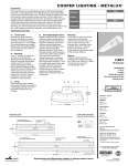
Model 922ECN ( Nat Gas )
Model 922ECP ( LP Gas )
Open Front
Decorative Vented Gas Fireplace
(With Coals)
Installation and Owner’s Manual
Please read this manual before installing and operating this heater
This manual should remain with the homeowner
WARNING: If the information in these
instructions is not followed exactly, a
fire or explosion may result causing
property damage, personal injury or
loss of life.
- Do not store or use gasoline or other
flammable vapors and liquids in the vicinity
of this or any other appliance.
-WHAT
TO DO IF YOU SMELL GAS
This appliance may be installed in an
aftermarket permanently located,
manufactured (mobile) home, where not
prohibited by local codes.
This appliance is only for use with the type of
gas indicated on the rating plate. This
appliance is not convertible for use with
other gases, unless a certified kit is used.
This appliance is a domestic room-heating
appliance. It must not be used for any other
purpose such as drying clothes etc.
•
•
Do not try to light any appliance.
Do not touch any electrical switch: do not
use any phone in your building.
• Immediately call your gas supplier from a
neighbor’s phone. Follow the gas supplier’s
instructions.
• If you cannot reach your gas supplier, call
the fire department.
- Installation and service must be performed
by a qualified installer, service agency or
the gas supplier.
This appliance is suitable for installation in a
bedroom or bed sitting room.
Warning: This product must be installed by
a licensed plumber or gas fitter when
installed within the Commonwealth of
Massachusetts
Manufactured by
MILES INDUSTRIES LTD.
British Columbia, Canada
Vous pouvez vous procurer un exemplaire en langue Française de cette brochure chez votre marchand.
4000192/03
CONTENTS
1.
2.
3.
4.
SAFETY INFORMATION ............................................................................................................................................................ 3
OPTIONS...................................................................................................................................................................................... 4
GENERAL DATA ......................................................................................................................................................................... 4
LOCATION IN THE ROOM ( insert application )………………………………………………………………………………… 5
( Z.C Application )………………………………………………………………..…………6
5. SUPPLY GAS............................................................................................................................................................................... 7
6. PACK CONTENTS ...................................................................................................................................................................... 7
7. APPLIANCE PREPARATION..................................................................................................................................................... 8
8. GAS SUPPLY INSTALLATION .................................................................................................................................................. 9
9. FIREBOX INSTALLATION ....................................................................................................................................................... 10
10. REMOTE CONTROL INSTALLATION..................................................................................................................................... 11
11.1 CERAMIC WALLS INSTALLATION ........................................................................................................................................ 12
11.2.CERAMIC COALS INSTALLATION ........................................................................................................................................ 13
12. ADORN CAST FRONT INSTALLATION……………………………………………………………………………….…………14
13. WINDSOR CAST ARCH FRONT INSTALLATION ................................................................................................................. 15
14. OPERATION CHECKS.............................................................................................................................................................. 16
15. OWNERS INFORMATION ........................................................................................................................................................ 17
Lighting instructions ............................................................................................................................................................... 19
2 of 19
1. SAFETY INFORMATION
Due to high temperatures, the appliance should
be located out of traffic and away from furniture
and draperies.
Children and adults should be alerted to the
hazards of high surface temperatures and should
stay away to avoid burns or clothing ignition.
Young children should be carefully supervised
when they are in the same room as the appliance.
Clothing or other flammable material should not
be placed on or near the appliance.
The safety guard must be put back in place prior
to operating the appliance if it has been removed
for servicing or cleaning.
This appliance should be installed and repaired
by a qualified service person.
The appliance should be inspected before use and
at least annually by a professional service person.
More frequent cleaning may be required due to
excessive lint from carpeting, bedding material,
etc. It is imperative that control compartments;
burners and circulating air passageways of the
appliance are kept clean.
If any changes are made to the room construction
in the vicinity of the appliance after installation
(e.g. additional mantle etc.) make sure that the
changes conform to the installation requirements
in this manual.
Never attempt to burn paper or any other
material in the appliance.
This appliance must be properly connected to a
venting system. The venting system should be
checked periodically. Recent trends in home
improvement and new tighter construction
techniques have contributed to problems with
venting. If you suspect that your appliance is not
venting properly, do not operate. Seek expert
advice.
Do not use this appliance if any part has been
under water. Immediately call a qualified service
technician to inspect the appliance and to replace
any part of the control system and any gas
control, which has been under water.
Only trim kits supplied by the manufacturer shall
be used in the installation of this appliance.
Draft openings must not be covered or blocked
Keep curtains, clothing, furniture and other
flammable materials a safe distance from all
parts of the appliance
Keep the appliance area well clear and free from
combustible materials, gasoline and other
flammable vapours and liquids.
NOTE
When operating your new fireplace for the first time, some vapors may be released due to the burning of curing compounds
used in the manufacture of the appliance. They may cause a slight odor and could cause the flames to be the full height of the
firebox, or even slightly higher, for the first few hours of operation. It is also possible that these vapors could set off any
smoke detection alarms in the immediate vicinity. These vapors are quite normal on new appliances and are totally harmless.
After a few hours use the vapors will have disappeared and the flames will be at their normal height.
During the first hour of use the ceramic firebox walls may go a smoky color. This is not soot. It is a temporary effect lasting
only while the ceramic material becomes stabilized. The walls will revert to their initial color after your fire has been used for
one or two hours.
3 of 19
2. OPTIONS
# 975 ZCK Zero Clearance Kit – for installation into combustible type framing.
# 976 BRK Bedroom kit: Includes optional thermostat hand set and wiring harness (for use in Canada only)
# 923 ACF Adorn Cast Front
# 539 or 549 Windsor Cast Arch front. (also requires #540WDK Wire Dress Guard)
# 3336 Closure Plate. For insert installations to cover up to 33” high x 36” wide
3. GENERAL DATA
This appliance is certified for use in Canada and the USA under the following standards :
ANSI Z21.50 – 2000 / CSA 2.22 –2000 , Vented Gas Fireplaces
Can/CGA 2.17 – M91 Gas Fired Appliances for use at High Altitudes.
This appliance must be installed in accordance with local codes, if any, or in the absence of local codes follow the National Fuel
Gas Code ANSI Z223.1 or Canadian Installation Code CAN-1-B149. Only qualified licensed or trained personnel should
install the appliance.
3.1 Venting
This appliance must be connected to an approved venting system.
3.2 Ratings
922ECN
Altitude (Ft)
Input Max. (Btu/h)
Input Min (Btu/h)
Manifold pressure (in w.c.)
Max Supply pressure (in w.c)
Min. Supply pressure (in. w.c.)
922ECP
0-4500
20,500
12,000
3.7
10.5
5
19,000
12,500
10.5
13
11
3.3 Choice of Cast Iron Front Trims
923 Adorn
539 Windsor Arch w/ Plate
549 Windsor Arch w/o Plate
Note : the 539/549 Fronts require a 540 WDK Wire Dress Guard with the 922 heater.
Cast Iron Tolerances – Due to the nature of Cast Iron, dimensional consistency may vary from one unit to the next and
some variation in surface finish and flatness is to be expected. We have done our best to control and make allowance,
however some variation is inevitable.
Closure plates may be required for insert applications where cast fronts do not cover entire openings.
Standard black 33” high x 36” wide closure plate with black aluminum extrusion edge is available.
4 of 19
4. LOCATION IN THE ROOM
This appliance must not be connected to a chimney flue serving a separate solid-fuel burning appliance.
Note: The State of Massachusetts requires that any flue damper must be removed or permanently welded in the open position.
The appliance can be installed in the following constructions:
4.1 Solid fuel (Non-combustible) fireplaces
As supplied, this appliance can be installed as an inset in an existing solid fuel type fireplace with a chimney and 4" dia
liner (see fig.1).
The fireplace must be built in accordance with the national, state provincial or territorial building code recognised by the
authority having jurisdiction, or in the absence of such a code, in accordance with the National Building Code of Canada or
the National Fire Protection Association code in the USA The size of the fireplace recess must be sufficient to
accommodate the appliance as shown in fig.1.
If previously used with for burning solid-fuel, the chimney must be swept before installation of the appliance. Both
chimney and fireplace must be checked for soundness before installation of the appliance. The liner must be a type
approved by the enforcing authority and installed in accordance with the manufacturer's instructions.
The appliance must be installed on a floor, which is sufficiently flat and level to ensure stability. Some fireplace
constructions have a well in the floor at the back that may need to be filled in.
Though not mandatory, we recommend that carpet, soft vinyl or other combustible floor coverings are kept at least 16”
from the front of the appliance since these types of materials may be affected by the radiant heat output from this appliance.
The minimum clearances from any combustible constructions at the front of the appliance are shown in fig.2
The appliance must be connected to a vent that is a minimum of 9’-0” in height and must not have any 90 deg. elbows
within 9’-0” of the flue outlet of the unit (see fig. 1). Radiused offsets in the flue liner of less than 90 degrees are
permitted.
Fig 1 . Insert Box dimensions and insert venting
Fig. 2 Clearances to combustible materials in front of opening - All installations
5 of 19
4.2 Enclosures Constructed Using Combustible Materials ( Z.C Installations)
Optional # 975 ZCK zero clearance kit must be used when installing the
922 Fireplace into any application other than as an insert into an approved
solid fuel burning fireplace cavity and chimney. Complete installation
instructions are packed with the 975 ZCK. See fig 2 for clearances in front
of appliance. The 975 ZCK is approved for installation directly on
combustible type flooring such as plywood. Bottom of 975 must be installed
at top of finished hearth (including tile etc.) or the removable ashpan cover
will not rest at the proper height. Cast iron fronts must also rest on a secure
hearth or floor as the unit is not intended to carry the weight of the castings.
The 975 ZCK may be roughed-in, wall finishes applied , and the fireplace
installed at a later date or the fireplace and Z.C kit may be installed at the
same time.
975 ZCK Assembled
975 ZCK Components
975 ZCK installed into Framing
Framing Dimensions
975 ZCK Wall Finish Details
6 of 19
5. SUPPLY GAS
Model 922ECN is for use only with natural gas. Model 922ECP is for use only with propane gas. The supply pressure must
be between the limits shown in section 3 of this manual.
The supply connection is 3/8”NPT male thread. The supply pipe connection is to a flexible connector at the left hand side of
the appliance.
6. PACK CONTENTS
This appliance requires more than one pack to complete the installation. The firebox unit is packaged separate from the front
trim. There is a choice of front trims to fit this unit (see section 3 of this manual). A 975 ZCK Zero Clearance Kit is
required when installing this appliance into any application other than as an insert into an approved solid fuel burning
fireplace.
922 - Firebox Unit contains:
1
1
1
1
2
3
1
1
1
1
4
1
Burner & box Unit
Ceramic Wall Pack
Coal support
Coal pack
Wall plugs
Screws
Flue spigot assembly
Remote control unit (including the following)
Receiver unit
Remote control hand unit
1.5V AA Batteries
9V Battery
One of the Optional front trims below must be used with this appliance ( see section 3 for diagrams)
923 - “Adorn” Cast Front: (comes complete with wire guard )
539 “Windsor Arch” cast front with back plate ( requires 540WDK wire guard when used with 922 firebox )
549 “ Windsor Arch “ cast front without back plate. ( requires 540 WDK wire guard when used with 922 firebox)
Note - The 540 WDK consists of a wire guard and mounting hardware as the Windsor Arch is not supplied with a wire
guard. Both the 539 and 549 Windsor Arch fronts are packaged with some redundant mounting hardware as they also fit other
models of fireboxes.
Take care when removing the contents from the packaging to prevent damage. Check that all the contents are in the packs and
are undamaged. Take special care in handling the ceramic walls and the coals.
7 of 19
7. APPLIANCE PREPARATION
7.1. Check ignition spark
The pilot burner and electrode unit is at the left end of the burner.
Push in the lighting knob and turn counter-clockwise through the “IGN” position
to “PILOT”. A spark should flash across from the pilot electrode to the pilot
burner shield. See figure 3.
7.2 Aeration Setting Check
The burner is equipped with an adjustable shutter to control primary aeration. See
figure 4. The shutter is factory set at an aeration gap, which will give optimum
performance for the vast majority of installations. In a few unusual installations
performance may be improved by adjusting the aeration. The need for adjustment
should be determined by operating the appliance with the ceramic fuel effects and
window installed. See the “Final checks” section in this manual for adjustment
details.
The shutter setting is very critical. A small change can make a substantial
difference to the performance.
Figure 3
7.3 Install Base Coal Support
Install base coal support ( packed loose ) to back of firebox using 3 screws as shown in fig 5 .
Fig 5
Figure 4
7.3 Remove Burner Module (optional)
In some cases, to make gas piping easier, it may be convenient to
remove the burner module from the firebox, see fig 6 (note the
location of the gas inlet before removing the burner module).
Remove 2 screws and pull the burner module partially out of the
firebox taking care not to pull on the wire leads going to vent
switch. With the module partly removed, reach behind the
module with a wrench and loosen the thermocouple nut at the
back of the valve. With the thermocouple nut loose, pull the vent
switch wire leads out of the brass block at the back of the valve
and pull the burner module the rest of the way out of the firebox.
Rough-in the gas line, valves, or unions and reinstall the burner
module.
Fig 6
8 of 19
8.
GAS SUPPLY INSTALLATION
1. The appliance is supplied for supply gas connection at the left hand
side of the case. There is also a gas line access at he rear of the firebox
for insert applications, see fig 7.The zero clearance kit does not have
access at the rear. Supply line connection to the flexible adapter is
3
/8”NPT male thread.
Alternatively, the appliance inlet pipe may be removed and the supply
line routed directly to the control unit. An isolating valve could be fitted
within the appliance case.
2. Use only new black iron or steel pipes or copper tubing if
acceptable - check local codes. Note that in USA copper tubing must be
internally tinned for protection against sulfur compounds.
3. Ensure there is a pipe union (or flare fitting where permissible)
ahead of the burner module for future servicing. Unions in gas lines
should be of ground joint type.
4. The gas supply line must be sized and installed to provide a supply
of gas sufficient to meet the maximum demand of the appliance without
undue loss of pressure.
Fig 7
5. Sealant used must be resistant to the action of all gas constituents
including LP gas. Sealant should be applied lightly to male threads to
ensure excess sealant does not enter gas lines.
6. The supply line should include a manual shut-off valve to allow the appliance to be disconnected for servicing.
A plugged 1/8”NPT tapping must be installed in the line. The tapping must be accessible for test gauge connection and be
immediately upstream of the gas supply connection to the appliance.
7.
Pressure test the supply line for leaks.
• The appliance and its individual shut-off valve must be disconnected from the gas supply piping system
during any pressure testing of that system at test pressures in excess of ½psig (3.5kPa).
• The appliance must be isolated from the gas supply piping system by closing its individual manual shut-off valve
during any pressure testing of the gas supply piping system at test pressures equal to or less than ½psig (3.5kPa).
• Failure to either disconnect or isolate the appliance during pressure testing may result in regulator or valve damage.
Consult your dealer in this case.
8. The minimum supply pressure is given in section 3 of this manual.
9. All piping and connections must be tested for leaks after installation or servicing. All leaks must be corrected
immediately.
When testing for leaks:
• Make sure that the appliance is turned off.
• Open the manual shut-off valve.
• Test for leaks by applying a liquid detergent or soap solution to all joints. Bubbles forming indicate a gas leak.
Never use an open flame to check for leaks.
Correct any leak detected immediately.
10. The pressure test tapping locations are shown in figure 8 . A built-in regulator controls the burner manifold pressure. The
correct pressure range is shown in the table in section 3 of this manual. The pressure check should be made with the burner
alight and the input set to its highest setting. See lighting instruction section for full operating details.
Figure 8
9 of 19
9. FIREBOX INSTALLATION ( insert Application only )
9.1 Refer to 975 ZCK installation Manual for Z.C Firebox installation.
9.2 To aid chimney liner connection it may be necessary to first remove the vent collar connector from the top of the firebox
( see fig 9a )
9.3 Remove the burner module from the firebox, see fig 9 .
9.4 Insert the convection box into the fireplace opening feeding the supply pipe through hole at back or side of the firebox see section 8.
9.5 Mark the fireplace floor through the two slots in the base of the convection box (see figure 9 ) and remove the convection
box. Drill two holes in the fireplace floor at the marked positions using a no.12 masonry drill.
9.6 Insert a wall plug into each hole.
9.7 Secure the collar on the vent connector unit to the 4" diameter chimney liner.
9.8 Slide the firebox into the fireplace making sure that the vent connection unit is above the convection box. Leave the firebox
front a few inches clear of the fireplace front to allow you to fix the vent connector to the top of the firebox.
9.9 With the vent connector started in the cleat pull the vent connector towards the front of the fireplace. Fix the front of the
vent connector plate to the firebox front flange using the screw previously removed (Fig 9a.).
9.10 Push the convection box fully home against the front face of the fireplace. Make sure that no sags or dips occur in the liner.
9.11 Fit a woodscrew through each slot in the convection box base and tighten.
9.12 Re-install the burner module and connect the gas supply line to the module ( see section 8 )
Fig 9 , Remove Burner Module and fasten firebox.
Fig 9a, Removing Vent Connector Plate.
10 of 19
10. REMOTE CONTROL INSTALLATION
Caution! Don’t connect the batteries to the remote control receiver until the wires are
connected to the burner control unit, as short circuit could result in destruction of the
electrical components.
When installing the remote please refer to figures 10 and 11.
•
•
•
•
•
•
Connect the wiring harness to the receiver box, by pushing the wire connector on to the receiver circuit
board. The plug will only go on one way so please ensure that the wires are pointing up and slot in the
board is inline with the tab on the wiring harness plug, see fig 11.
Connect wires as shown in fig 11 - Please note that the connectors are different sizes, the smaller one fits
to the lower connection on the valve.
Remove the remote control receiver lid.
Fit four 1.5V batteries.
Place the remote control receiver on the “Velcro” pad, see fig 10.
Fit the 9V battery to the handset transmitter
Remote control operating instructions are on page 17 of this manual and are supplied with the remote
control kit.
Figure 10
Figure 11 Valve connections
11 of 19
11. CERAMIC FUEL BED INSTALLATION
11.1. Ceramic Walls Installation
1.
Locate the ceramic rear wall on top of the base coal support as shown in fig 12.
2. Insert the right hand sidewall at approx 30 degree angle between the firebox side and the burner. Swing the top of the
sidewall to the vertical position and locate behind the upper baffle (see fig13).
3.
Repeat step 2 with left hand sidewall (Fig 13)
Fig 12 Back Brick Installation
Fig 13 Side Brick Installation
12 of 19
11.2. Ceramic Coals Installation
1. Rest the base coal on the supports just behind the burner and let it rest against the base coal support at the back of the
firebox. See fig 14.
2. Place the left front coal in position behind the metal lip at the front of the firebox. The side projection on this coal should
be near the middle front of the firebox. See figure15 .
3. Place the right front coal behind the metal lip at the front of the firebox. Its left side should rest over the projection on
the left front coal. See figure 16 .
4.
The center right coal has letter “R” embossed underneath. Place this coal behind the front right coal. See figure 17 .
5.
The center left coal has letter “L” embossed underneath. Place this coal behind the front left coal. See figure 18 .
Figure 16
Figure 15
Figure 14
Figure 17
Figure 18
13 of 19
12.
#923 ADORN CAST FRONT INSTALLATION
12.1
Carefully lift the casting. Place it against the fireplace front surface so that the retaining strip at the back of the casting
is above the two upper retaining brackets at the top of the convection box. Lower the casting making sure that the rear
retaining strip locates fully over the retaining brackets on the convection box (See figure 19).
12.3
Slide the front casting/surround sideways, if necessary, to align the bottom fixing holes with those in the convection
box. Fix the bottom of the casting/surround to the convection box with two screws (See figure 20).
Fig. 20 “Adorn” Front casting bottom fixing
Fig. 19 “Adorn” front casting top location
13.
13.1
ADORN SAFETY GUARD FITTING
Locate the guard bottom wires over the brass ash lip. Hold the top springs down. Swing the guard back. Release the
springs so that they locate behind the canopy (See figures 22 and 23).
Figure 21 Fitting “Adorn” safety guard
Fig 22
14 of 19
14.
#539/549 WINDSOR ARCH CAST FRONT INSTALLATION
14.1 All Windsor Arch fronts mounted to 922 fireboxes require a
540 WDK wireguard and mounting hardware, see fig 23.
Note – Bottom of Firebox must be installed flush with the
finished hearth height or casting will not install properly.
Castings must rest on secure hearth or floor as the
firebox and brackets will not support castings on their
own
14.2 Install mounting brackets and burner tray cover to the firebox
( see fig 24)
14.3 Install black Canopy Shield to cover openings in cast iron
canopy ( see fig 25 ). Lay inner cast front face down on the
floor. Insert one corner of the shield into the corner behind
the cast frame as shown. Bend the canopy shield to a slight
Fig 23 , 540 WDK Components
radius while inserting the other corner behind the cast frame
as shown ( it may be necessary to loosen or remove one or two of the canopy bolts). With both corners behind the cast
frame, snap the shield forward to follow the curve of the cast
iron canopy. The top of the shield should fit under the
projecting ledge in the casting as shown.
14.4 Fasten top filler piece to back side of Cast Arch ( see fig 26 )
14.5 Mount cast arch to brackets on firebox as shown in fig 27.
14.6 Hang inner casting on the outer arch and install wireguard as
shown in fig 27.
Fig 24 , bracket and burner tray cover installation
Fig 25 ,Canopy Shield Installation
Fig 26 , Top filler installation
Fig 27 , Mounting Cast Arch to Firebox.
15 of 19
15. OPERATION CHECKS
1.
Check ignition, pilot stability, burner flames, and the full range of
movement of the flame adjustment knob. See owner’s lighting
instructions further on in this manual for full details, see fig 28.
2.
Aeration adjustment
As described in section 17, burner aeration is adjustable. For the vast
majority of installations, no adjustment will be necessary. However, in a
very few instances, performance may be improved by adjusting the
aeration by sliding the shutter (See figure 4 page 8). Evaluate the aeration
only after the unit has warmed up – approximately 15 minutes.
The shutter setting is very sensitive. Small adjustments can make a
substantial difference to the flames
Fig 28, Pilot Flame location
Increasing aeration will cause the flame to appear more transparent and
blue making the ceramic fuel effects glow more.
Decreasing aeration will cause the flames to appear more yellow or orange making the fuel effects glow less. Too little
aeration may result in black carbon forming and dropping into the firebox.
3. Check venting efficiency
3.1 A check for correct venting of combustion products must be made before the installed appliance is left with the
customer.
You will need a mirror for this check.
3.2 The mirror must be cold and dry for the check so keep in a cool place such as a freezer compartment.y while the fire is
warming up.
3.4 Open the gas valve.
3.5 Light the appliance and set to high heat.Leave the appliance on for five minutes.
3.6 Make sure that the mirror is cold and dry. Place the mirror face downwards touching the bottom front of the black cross
member and angled slightly upwards so that the mirror face can be seen.(see fig 29)
3.7 The mirror face should remain clear for at least 5 seconds.
If condensation appears over the mirror face within 5 seconds the venting is not functioning properly. Don’t allow the
appliance to be used until the problem is cured.
Fig.29 Venting check with mirror
(Shown with “Adorn” front)
16 of 19
16. OWNERS INFORMATION
Please read the safety information and notes on page 3.
16.1. Operating Your Fire
The operating instructions are also on a chained plate inside the control access door.
1. For your safety this appliance is fitted with a flame supervision device which will shut off the gas supply if, for any
reason, the pilot flames go out. This device incorporates a fixed probe, which senses the heat from the pilot flame. If the
probe is cool, the device will prevent any gas flow unless the burner control knob is kept pushed in at the PILOT position.
See full lighting instructions on next page.
2. The Valor Remote Control System
Your Valor Remote Control helps you get the comfort, convenience and aesthetics you want from your Valor Gas Fireplace.
Setting the Flame
a. Press either of the large “up” or “down” buttons.
b. To raise the flame, press and hold the “up” button until you come to the flame level you want. Let go.
c. To lower the flame, press and hold the down button until you come to the flame you want. Let go.
d. The flame level will remain just as you set it.
3.When first turned on, the decorative flames will appear predominantly blue. After approximately 15 minutes the flames will
turn yellow.
16.2. Cleaning
Turn the fire off and allow it to cool before attempting any cleaning. Note that the fire will retain heat for some time after it
has been turned off.
Metal parts
Clean the metal parts with a slightly damp cloth and then dry. Do not use abrasive cleaners, they could scratch the surface.
Coals and ceramic firebox walls
Dust etc. Can be brushed from the coals using a soft bristle paintbrush after removing the safety guard. We suggest that you
remove the coals in the reverse order to that shown in fitting instructions. Make sure that no particles are brushed into the
ceramic burner slots.
17 of 19
16.3. Checks
1. A periodic check of the pilot and burner flames should be made. Check
after the fire has been on for at least 30 minutes. The pilot flame must cover
the tip of the thermocouple probe. The main burner flame pattern will vary
from appliance to appliance depending on the type of installation and climatic
conditions. See figures 30 and 31
2. The appliance area must always be kept clear and free from combustible
materials, gasoline and other flammable vapors and liquids.
3. Inspect the vent terminal outdoors regularly to make sure there are no
obstructions from birds nests, insects or rodents, etc.
4. Examine the whole vent system regularly. We recommend annually.
16.4. Servicing
All appliances use four 1.5V AA batteries for thermostat control.
The batteries used in the remote control receiver are accessible by opening
the bottom access panel and removing the lid of the remote control receiver.
The handset has a 9V battery.
Figure 30
16.5. General servicing
If you require any attention to your appliance, contact your supplier quoting
the model number. It will be helpful if the appliance serial number can also
be quoted. This is on the rating plate, which is on a chained, plate accessible
by opening the bottom access panel.
The repair parts are shown in the separate repair parts leaflet. Please always
quote part number and description when requesting spare parts.
Figure 31
18 of 19
YOUR SAFETY READ BEFORE LIGHTING
WARNING: If you do not follow these instructions exactly, a fire or explosion may result causing
property damage, personal injury or loss of life.
A. This appliance has a pilot, which must be lighted by hand. When lighting the pilot, follow these
instructions exactly.
B. BEFORE LIGHTING smell all around the appliance area for gas. Be sure to smell next to the floor
because some gas is heavier than air and will settle on the floor.
WHAT TO DO IF YOU SMELL GAS
•
Do not try to light any appliance.
•
Do not touch any electric switch; do not use any phone in your building.
•
Immediately call your gas supplier from a neighbor’s phone. Follow the gas supplier’s instructions.
•
If you cannot reach your gas supplier, call the fire department.
C. Use only your hand to push in or turn the control knobs. Never use tools. If the controls will not push in
or turn by hand, don’t try to repair them, call a qualified service technician. Force or attempted repair
may result in a fire or explosion.
D. Do not use this appliance if any part has been under water. Immediately call a qualified service
technician to inspect the appliance and to replace any part of the control system and any gas control,
which has been under water.
LIGHTING INSTRUCTIONS
1. STOP! Read the safety information above.
2. Set the flame adjustment knob as
far clockwise
as possible*.
to OFF.
3. Turn the gas control knob clockwise
NOTE: The knob cannot be turned from PILOT to OFF
unless it is pushed in partially. Do not force.
4. Wait five (5) minutes to clear out any gas, then smell
for gas, including near the floor. If you smell gas,
Flame
STOP! Follow “B” in the safety information above. If
Adjustment
you don’t smell gas, go to the next step.
Knob
5. Find the pilot. It is at the left side of the firebox
viewed through hole in front log.
6. Push in and turn the gas control knob counterclockwise
until resistance is felt just before the
“IGN” position.
7. Keep pushed in for a few seconds to allow gas to flow then, keeping knob depressed, turn to “PILOT”
to light pilot. Hold knob in for a further 5 seconds then release. The knob should pop back out. Pilot
should remain lit. If pilot goes out repeat steps 3 through 7.
• If knob does not pop out when released, stop and immediately call your service technician or gas
supplier.
• If pilot lights but will not stay lit after several tries, turn the gas control knob to “OFF” and call
your service technician or gas supplier.
8. When pilot is lit, partially depress the knob and turn to “ON” position (Burner alight).
• Do not leave knob set between “PILOT” and “ON”.
9. Set the flame height to desired setting*.
TO TURN OFF GAS TO APPLIANCE
as possible*
1.
Set the flame adjustment knob as far clockwise
2.
Push in gas control knob slightly and turn clockwise
to “OFF”. Do not force.
* The flame height can be increased or decreased by depressing the remote control hand set button.
19 of 19