1
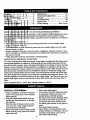
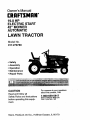
Owner's Manual
[RRFTSMRN°
19.0 HP
ELECTRIC START
42" MOWER
AUTOMATIC
LAWN TRACTOR
Model No.
917.270780
•
•
•
•
Safety
Assembly
Operation
Maintenance
• Repair Parts
CAUTION
Read and follow all
Safety Rules and Instructions
before operating this equipment.
Sears,
Roebuck
and Co., Hoffman
For answers to your questions
about this product, Call:
1-800-659-5917
Sears Craftsman Help Line
5 am - 5 pro, Mon- Sat
Estates,
IL 60179
...=....._,,.....;:-,............. 2
.............2
..._.>...:.-_..
.............5
.....
,=,...o,.,.....6
..... ,. .......... 11
................
16
Maintenance .........................................
18
Service and Adjustments ...................... 22
Storage .................................................
28
Troubleshooting ....................................
29
Repair Parts .........................................
34
Parts Ordering ....................... Back Cover
ON CRAFTSMAN
RIDING
EQUIPMENT
_te of purchase, if this Craftsman Riding Equipment is mainnec up _ccording to the instructions in the owner's manual,
Sears
tree!of charge, any parts found to be defective
_r:
in material or
I
I_eco'me worn during normal use, such as blades, spark
belts, ietc. !
• "13re
by punctures from outside objects, such as nails,
thorns, stumps, or glass.
• Repairs necessary because of operator abuse, negligence, improper storage or accident or the failure to maintain the equipment according to the instructions contained in
the owner's manual.
• Riding equipment used for commemial or rental purposes.
LIMITED
90 DAY WARRANTY
ON BAI-rERY
For ninety (90) days from date of purchase, if any battery included with this riding equipment proves defective in material or workmanship and our testing determines the battery will not hold a charge, Sears will replace the battery at no charge. In-home warranty
service on your Craftsman riding equipment is available at no charge for 30 days from
the date of pumhase. Please contact your nearest service center. After 30 days from the
date of purchase, warranty service is available by taking your Craftsman riding equipment to your nearest Sears Service Center. (In-home warranty service will still be available after 30 days from the date of purchase but a standard trip charge will apply). This
warranty applies only while this product is in the United States. This Warranty gives you
specific legal rights, and you may also have other rights which may vary from state to
state.
Sears, Roebuck and Co., D/817 WA, Hoffman Estates, IL 60179
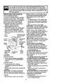
GENERAL
OPERAT_N
='_
• Read, understand, and follow all instructions in the manual and on the machine
before starting.
• Only allow responsible adult_, who are
familiar with the instructions, to operate
the machine.
• Clear the area of objects such as rocks,
toys, wire, etc., which could be picked
up and thrown by the blade.
• Be sure the area is clear of other people
bef_e mowing. Stop machine if anyone
enters the area.
Never carry passengers.
.
Do not mow in reverse unless absolutely necessary. Always look down and
behind before and while backing.
• Be aware of the mower discharge direction and do not point it at anyone. Do
not operate the mower without either
the entire grass catcher or the guard in
place.
• Slow down before turning.
• Never leave a running machine unattended. Always turn off blades, set park-ing brake, stop engine, and remove
-keys before dismounting.
•
•
•
•
•
•
• Donottrytostabilizethemachineby
putting your foot on the ground.
• Do not use grass catcher on steep
slopes.
Turn off blades when not mowing.
Stop engine before removing grass
catcher or unclogging chute.
Mow only in daylight or good artificial
light.
Do not operate the machine while under
the influence of alcohol or drugs.
Watch for traffic when operating near or
crossing roadways.
Use extra care when loading or unloading the machine into a trailer or truck.
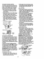
SLOPE
CHILDREN
Tragic accidents can occur if the operator
is not alert to the presence of children.
Children are often attracted to the
machine and the mowing activity. Never
assume that children will remain where
you last saw them.
• Keep children out of the mowing area
and under the watchful care of another
OPERATION
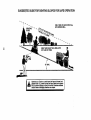
Slopes are a major factor related to lossof-control and tipover accidents, which
can result in severe injury or death. All
slopes require extra caution. If you cannot
back up the slope or if you feel uneasy on
it, do not mow if.
DO:
responsible adult.
• Be alert and tum machine off if children
enter the area.
• Before and when backing, look behind
and down for small children.
• Never carry children. They may fall off
and be seriously injured or interfere with
safe machine operation.
• Never allow children to operate the
machine.
• Mow up and down slopes, not across.
• Remove obstacles such as rocks, tree
limbs, etc.
• Watch for holes, ruts, or bumps. Uneven
terrain could overturn the machine. Tall
• Use extra care when approaching blind
corners, shrubs, trees, or other objects
that may obscure vision.
grass can hide obstacles.
• Use slow speed. Choose a low gear so
that you will not have to stop or shift
while on the slope.
• Follow the manufacturer's recommen-
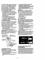
SERVICE
• Use extra care in handling gasoline and
other fuels. They are flammable and
vapors are explosive.
Use only an approved container.
Never remove gas cap or add fuel
with the engine running. Allow engine to cool before refueling. Do not
smoke.
Never refuel the machine indoors.
Never store the machine or fuel
container inside where there is an
open flame, such as a water heater.
• Never run a machine inside a closed
area.
• Keep nuts and bolts, especially blade
attachment bolts, tight and keep equipment in good condition.
dations for wheel weights or counterweights to improve stability.
• Use extra care with grass catchers or
other attachments. These can change
the stability of the machine.
• Keep all movement on the slopes slow
and gradual. Do not make sudden
changes in speed or direction.
• Avoid starting or stopping on a slope. If
tires-iose traction, disengage the blades
and proceed slowly ,_ig_own
slope.
DO NOT:
the
• Do notturn on slopes unless necessary,
and then, turn slowly and gradually
downhill, if possible.
• Do not mow near drop-offs, ditches, or
embankments. The mower could suddenly turn over if a wheel is over the
edge of a cliff or ditch, or if an edge
caves in.
r
• Do not mow on wet grass. Reduced
tr_actioh could cause sliding.
3
their proper
operation
regularly.
_ Check
ever tamper
with safety
devices.
Keep machine free of grass, leaves, or
other debris build-up. Clean oil or fuel
spillage. Allow machine to cool before
storing.
Stop and inspect the equipment if you
strike an object. Repair, if necessary,
before restarting.
_e ad'._stmentss or r_epairs _ithn
_runr_ng.
_m'ner c_omponer_ts a_e subject
_amag_,
and de_edoDration,
Jutd exl_ose mowing I_arts or
_ts to_i:be throwm. F--_,equent_ly
,-mponemts and r_plaace with_
uJrer's rrecorna'n_-_ndeed parts,
_--=ssaryy.
• _Vtowerl_lac_e_sare_h_rp
a_nd_ can cut.
WVra@ _
btl_zu:_e(s) _r _weatr gloves, and
uuse extzca c_uJtmon w_he_n s_rv_cing them.
. _heck
_ral_a o_oera_tiom fr_qt_ently.
PAdjt._-'t _nd servvice as Te_uired.
are_ is clear :of o_her people
.-_wing. _Stop rnacchineg_ if anyon_
• Mvlow_ u_ and d_own slc_e_
.= £area.
o F_ermove9 obstEctes
such _s rocks, tree
:]limbs, =_tc.
° WVat_n f_or h_ole=...s,runs. for t_urr_s. Uneven
t_rr_in
_oulr'J owertwm
-the- machine. Tall
(15 ° Max), not
-,?._Cr(_3 s.
passsengers.
mw in re,verse ur.nlesss absol__rry. Alwvays $ook_, do_wn and
-_,mre a_qd wt-_le i=oackiang.
chilo:lren. They
rnaay fall off
_ioustw
injured o0r in_effere _wit_
.-nine o!:_eration.
c_ren ouut of t_e rmow,ing area
r .-the w_atchful caare oof anoth_er
_e_ aduldt.
_rnd turrn mac_ir_e offf ff children
_1 where backing;i, Ioo_k behind
_'ffor sn'_all ct'_ldm=en.
ogras_ c_an t_i_
ob_'ta_les.
• LUse slowv soee=_d. C_hoosm_a low gear so
'_-J'_at3,ouJ willl no_t hm_e ,-m E._op or shift
v_hile om the stoope;
• A_voiid _,_'_g
_or stmp_in_
on a slope. If
ti_res :los÷e tr_cticon, dis_n(_age
the blades
sand _pro=cee_l st_owly¢ srtrai_ht down the
sstop_.
• _o n_ot'_um on _topms:,unle_ss
necessary,
sand tthe_n, turn _._stowdyan_t_gra_lually
adow_i'nilltl, if posssible.
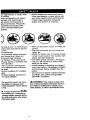
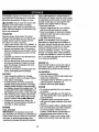
.-troissyFrnbol to pooint lout impor-_cautJtions.
It maeanss CAU;;;DMEA_WARI_!!E
YCDUR SP_FELVED..
_,YWA_INIING:
_
_mgime e_xhaust from
thiss prmclL=ct contsain$¢hmmim.,als
known to
th_Sta_te_eof
C_lif0omia_'t_camse
cancer,
birttt_ d_fe_:_s, or o_therr,_'e_rod_uctfve harm.
a_t'ea.
_1_:In o_'der to p_eve_t
acci_ten-_hen s_etting up, _trarmsporting,
rmakir_g repairs-;alwaays
dis_or__tq.g wi_,_e and pta_ce vwire wh_r_.
_ltact sppark p_ug;;.
4
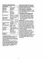
PRODUCT
Please read and rtain this manual. The
instructionswill enable you to assemble
and maintain your tractor pr pedy.Always
observe the "SAFETY RULES".
SPECIFICATIONS
HORSEPOWER
19.0
GASOLINE
3APACITY
_,ND TYPE:
3.5 GALLONS
UNLEADED
REGULAR
)ILTYPE
SAE 30
API-SF/SG/SH):
(above 32°F)
SAE 5W-30
MAINTENANCE
A Sears Maintenance Agr ement is available on this product. Contact your near st
Sears stor for details.
CUSTOMER RESPONSIBILITIES
(below 32°F)
DIL CAPACITY:
W/FILTER
3.5 PINTS
W/O FILTER 3,0 PINTS
SPARK PLUG:
GAP: .030")
Champion RJ19LM
OR J19LM
VALVE CLEARANCE:
INTAKE:
.004-.006
EXHAUST:
.007-.009
GROUND SPEED
FORWARD:
0-5.5
IMPH):
REVERSE:
0-2.4
TIRE PRESSURE:
FRONT: 14 PSI
REAR: 10 PSI
CHARGING
SYSTEM:
3 AMPS BATTERY
5 AMPS HEADLIGHTS
BATTERY:
AMP/HR:30
MIN. CCA:240
CASE SIZE: U1R
BLADE BOLT
TORQUE:
AGREEMENT
• Read and observe the safety rules.
• Follow a r gular schedule in maintaining, caring for and using your tractor.
• Follow the instructions under "Maintenance" and "Storage"
owner's manual.
sections of this
_,WARNING:
This tractor is equipped
with an internal combustion engine and
should not be used on or near any unimproved forest-covered, brush-covered or
grass-covered land unless the engine's
exhaust system is equipped with a spark
arrester meeting applicable local or state
laws (if any). If a spark arrester is used, it
should be maintained in effective working
order by the operator.
In the state of California the above is
required by law (Section 4442 of the
California Public Resources Code). Other
states may have similar laws. Federal
laws apply on federal lands. A spark
arrester for the muffler is available through
your nearest Sears Authorized Service
Center (See REPAIR PARTS section of
this manual).
27-35 FT. LBS.
CONGRATULATIONS
on your purchase
of a Craftsman Tractor. It has been
designed, engineer d and manufactur d
to give you the best possible dependability
and performance.
Should you experience any pr blem you
cannot easily r medy, please contact your
near st Sears Authorized Service Center.
We h_ve competent, well-trained technicians and the proper to_lsj_o,,_serviceor
repair this tractor.
;
5
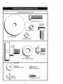
Parts Bag contents shown full size
(1) Hex Bolt 5/16-18 x 1-1/4
(1) Hex Bolt
3/8-16 x I
(1) Lockwasher 3/8
@
(1) LargeFlat Washer
(1) Locknut 5/16-18
(1) Knob
(1) Shoulder
Bolt 5/-16-18
(1) Washer
17/32 x 1-3/16 x 12 Gauge
(2) Washers
3/16 x 3/4 x 16 Gauge
(2) Weld
Nuts #10
_
(2) Lock #10
Washers
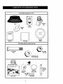
Pads packed separately in carton
D
Steedng
Boot
Seat
Video
Cassette
Mulcher
Rate
I
f
!
I
I
i
I
iI
I
Steering
Wheel
=
Manual
Parts Bag
Pads Bag contents not shown full size
2) Center(2) Shoulder
Bolts
lock Nuts
12)Washers 3/8
x 7/8 x 14 Gauge
iL_._r--
Steering Wheel Adapter
(2) Gauge
Wheels
(2) Keys _
_mbr_
Slope Sheet
7
Extension
Shaft
Steering
Wheel Insert
t
Steering
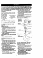
Your new tractor has been assembled at the factory with exception of those parts left
unassembled for shipping purposes. To ensure safe and proper operation of your tractor
all pads and hardware you assemble must be tightened securely. Use the correct tools
as necessary to insure proper tightness. Review the video cassette before you begin.
TOOLS REQUIRED
FOR
ASSEMBLY
A socket wrench set will make assembly
easier. Standard wrench sizes you need
are listed below.
(1) 3/4" Socket w/
(1) 9/16" wrench
drive ratchet
(2) 1/2" wrench
(1) Phillips Screw(1) Utility knife
driver
(1) Tire pressure
gauge
When right or left hand is mentioned in
this manual, it means, from your point of
view, when you are in the operating position (seated behind the steering wheel).
TO REMOVE
TRACTOR
FROM
CARTON
UNPACK CARTON
• Remove all accessible loose parts and
parts boxes from shipping carton (See
page 6).
• Cut, from top to bottom, along lines on
all four corners of shipping carton, and
lay panels flat.
• Check for any additional loose parts or
boxes and remove.
BEFORE
SKID
ATrACH
ROLLING
TRACTOR
OFF
• Assemble large flat washer, 3/8 lock
washer, 3/8 hex bolt and tighten securely.
• Snap steering wheel insert into center
of steering wheel.
• Remove protective materials from tractor hood and grill.
IMPORTANT:
Check for and remove any
staples in skid that may puncture tires
where tractor is to roll off skid.
@ 8.exBe.
Insert
3/8 Lock
Steering
Wheel --_
"_
_
../_:-_.
_L..
_-_J_
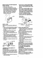
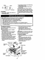
ASSEMBLE
BOOT
WHEEL
EXTENSION
• Slide extension
SHAFT AND
shaft onto lower steer-
ing shaft. Align mounting holes in extension andlower shafts and install 5/16
hex bolt and Iocknut. Tighten securely.
IMPORTANT: Tighten bolPah'_t'ffut securely to 18-22 ft. Ibs. torque.
• Place tabs of steering boot over tab
slots in dash and push down to secure.
INSTALL STEERING WHEEL
• Position front wheels of the tractor so
they are pointing straight forward.
• Slide steering wheel adapter onto steering shaft extension.
• Position steering wheel so cross bars
are horizontal (left to right) and slide
in,de boot and onto adapter.
_J!
_ _ Large Flat
Washer
]_ring
Boot
Tabs
Adapter _
_
Extension Shaft
"_._/"
5116 Hex
5/16 Lock Nut __
Bolt
Lower
STEERING
Washer
_
-_"--_ ,_L
Steering Shaft,-------,-_..__jb
i\
,
"
-.
"'
Tabs
_1/_
"''-'i
'f'"
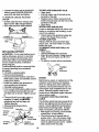
TO ROLL TRACTOR OFF SKID (See
Operation section for location and
function of controls)
• Press lift lever plunger and raise attachment lift lever to its highest position.
• Release parking brake by depressing
clutch/brake pedal.
• Place freewheel control in freewheeling
position to disengage transmission (See
"TO TRANSPORT"
in the Operation
section of this manual).
• Roll tractor forward off skid.
• Remove banding holding discharge
guard up against tractor.
HOW TO SET UP YOUR TRACTOR
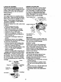
CHECK BATTERY
• Adjust mower to desired cutting height
(See "TO ADJUST MOWER CUTTING
HEIGHT" in the Operation section of this
manual).
• With mower in desired height of cut position, gauge wheels should be assembled so they are slightly off the ground.
Install gauge wheel in appropriate hole
with shoulder bolt, 318 washer, and 3/8-
• Lift hood to raised position.
• If this battery is put into service after
month and year indicated on label (label
located between terminals) charge battery for minimum of one hour at 6-10
amps. (See "BATTERY" in MAINTENANCE section of this manual for
16 Iocknut and tighten securely.
• Repeat for opposite side installing
gauge wheel in same adjustment hole.
charging instructions).
:..=
:"
_"
Gauge Wheel
Label
MountingBracket
:..
_\
•
_ ",+,++
INSTALL
3/8-16Locknut /
SEAT
3/8 Washer /
Adjust seat before tightening adjustment
knob.
• Remove cardboard packing on seat pan.
• Place seat on seat pan and assemble
shoulder bolt. Tighten shoulder bolt
securely.
• Assemble adjustment knob and flat
washer loosely. Do not tighten.
• Lower seat into operating position and
sit on seat.
Seat Pan _
Shoulder
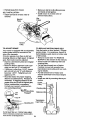
ASSEMBLE
GAUGE
MOWER DECK
Seat
Rat Washer
WHEELS
Bolt
hook by inserting weld nut from the top
with hook pointing down.
• Tighten hardware securely.
• Raise and hold deflector shield in upright position.
• Place front of mulcher plate over front of
mower dock opening and slide into
place, as shown.
• Hook front latch into hole on front of
mower deck.
• Hook rear latch into hole on back of
mower deck.
,_CAUTION:
Do not remove discharge
guard from mower. Raise and hold guard
when attaching mulcher plate and allow it
to rest on plate while in operation.
TO CONVERT TO BAGGING OR
DISCHARGING
_===
AdnJoU,
Stment "__
_._,,_/Shoulder
Gauge Wheel
INSTALL MULCHER PLATE
• Install two latch hooks to mulcher plate
using screw, washer, lock washer, and
weld nut as shown.
NOTE: Pre-assemble weld nut to latch
• Slide seat until a comfortable position is
reached which allows you to press
clutch/brake pedal all the way down.
• Get off seat without moving its adjusted
position.
• Raise seat and tighten adjustment knob
securely.
-
_ _._F_
TO
Simply remove mulcher plate and store in
a safe place. Your mower is now ready for
discharging or installation of optional grass
catcher accessory.
NOTE: It is not necessary to change
blades. The mulcher blades are designed
for discharging and bagging also.
The gauge wheels are designed to keep
the mower deck in proper position when
operating mower. Be sure they are properly adjusted to ensure optimum mower performance.
• -Assemble gauge whee!s with tractor on
a flat level surface.
9
Hook Points
Down
Weld Nut From
The Top
Weld
Lock
Washer
V' CHECKLIST
PLEASE REVIEW
CHECKLIST:
V' All assembly instructions have been
completed.
v' No i'emaining
Latch
Latch
LockWasher
Washer
Washer
'_._
loose parts in carton.
Battery is properly prepared and
charged. (Minimum I hour at 6 amps).
v' Seat is adjusted comfortably and
tightened securely.
All tires are properly inflated. (For
shipping purposes, the tires were
overinflated at the factory).
i/ Be sure mower deck is properly leveled
side-to-side/front-to-rear
for best
Nut
Mulcher
Plate
THE FOLLOWING
Screw
Deflector
cutting results. (Tires must be properly
inflated for leveling).
V' Check mower and drive belts. Be sure
they are routed properly around pulleys
and inside all belt keepers.
V' Check wiring. See that all connections
are still secure and wires are properly
clamped.
Latch
Hooks
CHECK
i,' Before driving tractor, be sure freewheel control is in drive position.
TIRE PRESSURE
WHILE LEARNING HOW TO USE YOUR
TRACTOR,
PAY EXTRA ATI-ENTION TO
THE FOLLOWING IMPORTANT ITEMS:
The tires on your tractor were overinflated
at the factory for shipping purposes.
Correct tire pressure is important for best
cutting performance.
• Reduce tire pressure to PSI shown in
"PRODUCT SPECIFICATIONS"
section
of this manual.
CHECK
/
,/
•/
DECK LEVELNESS
Engine oil is at proper level.
Fuel tank is filled with fresh, clean,
regular unleaded gasoline.
Become familiar with all controls - their
location and function. Operate them
before you start the engine.
For best cutting results, mower housing
should be properly leveled. See =TO
LEVEL MOWER HOUSING" in the
,/
Service and Adjustments section of this
manual.
,/
CHECK FOR PROPER POSITION OF
ALL BI_LTS
See the figures that are_o_Jor
replacing motion and mower bTa-dedrive belts in
the Service and Adjustments sectoin of
this manual. Verily that the belts are routed correctly.
CHECK BRAKE SYSTEM
After you leam how to operate your tractor, check to see that the brake is propedy
adjusted. See "TO ADJUST BRAKE" in
• the Service and Adjustments section of
this manual.
10
Be sure brake system is in safe operating condition.
It is important to purge the transmission before operating your tractor for
the first time. Follow proper starting
and transmission purging instructions
(See =TO START ENGINE" and
=PURGE TRANSMISSION"
in the Operation section of this manual).
These symbols may appear on your tractor or in literature
Learn and understand their meaning.
BATTERY
CAUTION OR
WARNING
REVERSE
ENGINE ON
ENGINE OFF
OIL PRESSURE
supplied with the product.
FORWARD
FAST
SLOW
LIGHTS ON
®
FUEL
CHOKE
MOWER HEIGHT
PARKING BRAKE
LOCKED
UNLOCKED
MOWER LIFT
R N H L
ATTACHMENT
CLUTCH ENGAGED
REVERSE
NEUTRAL
HIGH
LOW
PARKING BRAKE
KEEP AREA CLEAR
IGNITION
ATTACHMENT
CLUTCH DISENGAGED
(SEE SAFETY RULES SECTION)
FREE WHEEL
(AutomaticModels only)
DANGER, KEEP HANDS AND FEET AWAY
11
KNOW YOUR TRACTOR
READTHISOWNER'SMANUALAND SAFETYRULESBEFOREOPERATINGYOUR
TRACTOR
Compare the illustrations with your tractor to familiarize yourself with the locations of
various controls and adjustments.
Save this manual for future reference.
Attachment
Clutch Lever
Ignition
Switch
Light Switch
Position
Ammeter
Lift Lever
Choke
Throttle Control
Attachment
Clutch/Brake
Pedal
Freewheel
Control
Parking Brake
Motion
Control Lever
Our tractors conform to the safety standards of the American
National Standards Institute.
MOTION CONTROL LEVER: Selects the
speed and direction of the tractor.
ATTACHMENT LIFT LEVER: Used to raise and
lower the mower deck or other attachments
mounted to your tractor.
LIFT LEVER PLUNGER: Used to release
attachment lift lever when changing its position.
IGNITION SWITCH: Used for starting and stopping the engine.
AMMETER: Indicates battery charging (+) or
discharging (-).
PARKING BRAKE: Locks clutchibrake into the
brake position.
ATTACHMENT CLUTCH LEVER: Used to
engage the mower blades, or other attachments
mounted to your tractor. _-:
LIGHT SWITCH: Tums the headlights on and
off.
CHOKE CONTROL: Used when starting a cold
engine.
THRO'rrLE CONTROL: Used to controlengine
speed.
CLUTCH/BRAKE PEDAL: Used for declutching and braking the tractor and starling the
engine.
FREEWHEEL CON]'ROL: Disengages transmissionfor pushing or slowly towing the tractor
with the engine off.
12
The operationof anytractorcan resultin foreign
objects thrown into the
eyes, which can result in severe eye damage. Always wear safety glasses
or eye shields while operating your tractor or performing any adjustments or
repairs. We recommend a wide vision safety mask over spectacles, or standard safety glasses.
I
HOW
TO USE
YOUR
TO SET PARKING
TRACTOR
BRAKE
Your tractor is equipped with an operator
presence sensing switch. When engine
is running, any attempt by the operator to
leave the seat without first setting the
parking brake will shut off the engine.
• Depress clutch/brake pedal into full
"BRAKE" position and hold.
• Place parking brake lever in
=ENGAGED" position and release pressure from clutch/brake pedal. Pedal
should remain in "BRAKE" position.
Make sure parking brake will hold tractor secure.
Choke
Control
Attachment Clutch
Lever =Engaged"
Position
"Disengaged"
Control
Parking Brake
"Engaged"
Posi_on
"Brake"
Pedal"Ddve"
Posi_on
"Disengaged"
PosiSon
NOTE:
• Turn ignition key to "OFP position and
remove key. Always remove key when
leaving tractor to prevent unauthorized
use.
• Never use choke to stop engine.
IMPORTANT"
Leaving the ignition switch
in any position other than =OFP will cause
the battery to be discharged, (dead).
NOTE; Under certain conditions when
tractor is standing idle with the engine running, hot engine exhaust gases may
cause "browning" of grass. To eliminate
this possibility, always stop engine when
stopping tractor on grass areas.
A CAUTION:
Always stop tractor completely, as described above, before leaving
the operator's position; to empty grass
catcher, etc.
TO USE THROTTLE CONTROL
Always operate engine at full throttle.
• Operating engine at less than full throttle reduces the battery charging rate.
• Full throttle offers the best bagging and
mower performance.
TO USE CHOKE CONTROL
MoUon
Control
Lever
Use choke control whenever you are starting a cold engine. Do not use to start a
warm engine.
• To engage choke control, pull knob out.
Slowly push knob in to disengage.
TO MOVE FORWARD AND BACKWARD
STOPPING
MOWER
BLADES-
• To stop mower blades, move attachme.ot clutch lever to "DISENGAGED"
position.
GROUND
The direction and speed of movement is
controlled by the motion control lever.
• Start tractor with motion control lever in
DRIVE -
• To stop ground drive, depress
clutch/brake pedal into full "BRAKE"
position.
• Move motion control lever to neutral (N)
position.
IMPORTANT: The motion control lever
does not return to neutral (N) position
when the clutch/brake pedal is depressed.
ENGINE
Failure to move throttle control to
slow position and allowing engine to idle
before stopping may cause engine to
"backfire".
neutral (N) position.
• Release parking brake and clutch/brake
pedal.
• Slowly move motion control lever to
desired position.
TO ADJUST MOWER cu'rrlNG
HEIGHT
The position of the attachment lift lever
determines the cutting height.
• Grasp lift lever.
• Press plunger with thumb and move
lever to desired position.
-
• Move throttle control to slow position.;
13
The cutting height rangeis approximately 1-1/2to 4". The heights are measured
from the ground to the blade tip with the
engine not running. These heights are
approximate and may vary depending
upon soil conditions, height of grass and
types of grass being mowed.
• The average lawn should be cut to
approximately 2-1/2 inches during the
cool season and to over 3 inches during
hot months. For healthier and better
looking lawns, mow often and after
moderate growth.
• For best cutting performance, grass
over 6 inches in height should be
mowed twice. Make the first cut relatively high; the second to desired height.
TO OPERATE MOWER
Your tractor is equipped with an operator
presence sensing switch. Any attempt by
the operator to leave the seat with the
engine running and the attachment clutch
engaged will shut off the engine.
• Select desired height of cut.
• Start mower blades by engaging attachment clutch control.
• TO STOP MOWER BLADES - disenpage
attachment clutch control.
CAUTION:
Do not operate the mower
without either the entire grass catcher, on
mowers so equipped, or the discharge
guard in place.
Attachment Clutch
Lever "Engaged"
"Disengaged"
Attachment Lift
Lever High Position
._:'
• If slowing is necessary, move throttle
control lever to slower position.
• If stopping is absolutely necessary, push
clutch/brake pedal quickly to brake position and engage parking brake.
• Move motion control lever to neutral (N)
position.
IMPORTANT: The motion control lever
does not return to neutral (N) position
when the clutch/brake pedal is depressed.
• To restart movement, slowly release
parking brake and clutch/brake pedal.
• Slowly move motion control lever to
slowest setting.
• Make all turns slowly.
TO TRANSPORT
When pushing or towing your tractor, be
sure to disengage transmission by placing
freewheel control in freewheeling
position.
Freewheel control is located at the rear
drawbar of tractor.
• Raise attachment lift to highest position
with attachment lift control.
• Pull freewheel control knob out and hold
in position by inserting retainer spring
into forward hole of control rod.
• Do not push or tow tractor at more than
two (2) MPH.
• To reengage transmission,
reverse
above procedure.
NOTE: To protect hood from damage when
transporting your tractor on a truck or a
trailer, be sure hood is closed and secured
to tractor. Use an appropriate means of
tying hood to tractor (rope, cord, etc.).
Low
TOWING CARTS AND OTHER
ATTACHMENTS
TO OPERATE
_,CAUTION:
Tow only the attachments that are recommendedby and comply with specifications
of the manufacturer of your tractor. Use
common sense when towing. Too heavy of
a load while on a slope, is dangerous.
Tires can lose tract on w th the ground and
cause you to lose control of your tractor.
ON HILLS
Do not drive up or down
hills with slopes greater than 15 ° and do
not drive across any slope.
• Choose the slowest speed before starting up or down hills.
• Avoid stopping or changing speed on
hills.
14
BEFORE
STARTING
THE ENGINE
CHECK ENGINE OIL LEVEL
• The engine in your tractor has been
shipped, from the factory, already filled
with summer weight oil.
• Check engine oil with tractor on level
ground.
• Remove oil fill cap/dipstick and wipe
clean, reinsert the dipstick and screw
cap tight, wait for a few seconds,
remove and read oil level. If necessary,
add oil until "FULL" mark on dipstick is
reached. Do not overfill.
• For cold weather operation you should
change oil for easier starting (See "OIL
VISCOSITY CHART" in the Maintenance section of this manual).
• To change engine oil, see the Maintenance section in this manual.
ADD
GASOLINE
• Fill fuel tank. Use fresh, clean, regular
unleaded gasoline with a minimum of 87
octane. (Use of leaded gasoline will
increase carbon and lead oxide
deposits and reduce valve life). Do not
mix oil with gasoline. Purchase fuel in
quantities that can be used within 30
days to assure fuel freshness.
IMPORTANT:
When operating in temperatures below 32°F(0°C), use fresh, clean
winter grade gasoline to help insure good
,_NAweather starting.
RNING: Experience indicates that
alcohol blended fuels (called gasohol or
using ethanol or methanol) can attract
moisture which leads to separation and
formation of acids during storage. Acidic
gas can damage the fuel system of an
engine while in storage. To avoid engil3e
problems, the fuel system should be emptied before storage of 30 days or longer.
Drain the gas tank, start the engine and let
it run until the fuel lines and carburetor are
• Be sure freewheel control is in the
transmission engaged position.
• Sit on seat in operating position,
depress clutch/brake pedal and set
parking brake.
• Place motion control lever in neutral (N)
position.
• Move attachment clutch to "DISENGAGED" position.
• Move throttle control to fast position
• Pull choke control out for a cold engine
start attempt. For a warm engine start
attempt the choke control may not be
needed.
NOTE: Before starting, read the warm and
cold starting procedures below.
• Insert key into ignition and turn key
clockwise to "START" position and
release key as soon as engine starts.
Do not run starter continuously for more
than fifteen seconds per minute. If the
engine does not start after several
attempts, push choke control in, wait a
few minutes and try again. If engine still
does not start, pull the choke control out
and retry.
WARM WEATHER
AND ABOVE)
STARTING
(50 ° F
• When engine starts, slowly push choke
control in until the engine begins to run
smoothly. If the engine starts to run
roughly, pull the choke control out slightly for a few seconds and then continue
to push the control in slowly.
• The attachments and ground drive can
now be used. If the engine does not
accept the load, restart the engine and
allow it to warm up for one minute using
the choke as described above.
COLD WEATHER
BELOW)
STARTING
(50 ° F AND
• When engine starts, slowly push choke
control in until the engine begins to run
smoothly. Continue to push the choke
control in small steps allowing the
engine to accept small changes in
speed and load, until the choke control
is fully in. If the engine starts to run
roughly, pull the choke control out slightly for a few seconds and then continue
to push the control in slowly. This may
require an engine warm-up period from
several seconds to several minutes,
depending on the temperature.
empty. Use fresh fuel rNY_t_vason. See
Storage Instructions for additional information. Never use engine or carburetor
cleaner products in the fuel tank or permaznt damage may occur.
CAUTION: Fill to bottom of gas tank
filler neck. Do not overfill. Wipe off any
spilled oil or fuel. Do not store, spill or use
gasoline near an open flame.
TO START ENGINE
When starting the engine for the first time
or if the_ngine has run out of fuel, it will
take extra cranking time to move fuel from
the tank to the engine.
15
AUTOMATICTRANSMISSION
WARM-UP
• Before driving the unit in cold weather,
the transmission
should be warmed up
as follows:
• Be sure the tractor is on level ground.
• Place the motion control lever in neutral. Release the parking brake and
let the clutch/brake slowly return to
operating position.
• Allow one minute for transmission to
NOTE: During this procedure there will be
no movement of drive wheels. The air is
being removed from hydraulic drive system.
• Move motion control lever to neutral (N)
position. Shut off engine and set parking
brake.
• Engage transmission by placing freewheel control in driving position (See
"TO TRANSPORT"
in this section of
manual).
• Sitting in the tractor seat, start engine.
After the engine is running, move throttle control to half (1/2) speed. With
motion control lever in neutral (N) position, slowly disengage clutch/brake
pedal.
• Slowly move motion control lever forward; after the tractor moves approximately five (5) feet, slowly move motion
control lever to reverse position. After
the tractor moves approximately five (5)
feet return the motion control lever to
the neutral (N) position. Repeat this procedure with the motion control lever
three (3) times.
• Your tractor is now purged and ready for
normal operation.
MOWING
TIPS
• Mower should be properly leveled for
best mowing performance. See "TO
LEVEL MOWER HOUSING" in the
Service and Adjustments section of this
manual.
• The left hand side of mower should be
warm up. This can be done during the
engine warm up period.
• The attachments
can be used during
the engine warm-up period after the
transmission has been warmed up and
may require the choke control be pulled
out slightly.
NOTE: A high altitude (above 3000 feet)
or in cold temperatures
(below 32 F) the
carburetor fuel mixture may need to be
adjusted for best engine performance.
See "TO ADJUST CARBURETOR"
in the
Service and Adjustments section of this
manual.
,_RGE TRANSMISSION
CAUTION: Never engage or disengage freewheel lever while the engine is
running.
To ensure proper operation and performance, it is recommended that the transmission be purged before operating tractor
for the first time. This procedure will
remove any trapped air inside the transmission which may have developed during
shipping of your tractor.
IMPORTANT:
Should your transmission
require removal for service or replacement, it should be purged after reinstallation before operating the tractor.
• Place tractor safely on level surface with
engine off and parking brake set.
• Disengage transmission by placing freewheel control in freew_._el_g, position
(See "TO TRANSPOR'_
irilhis section
of manual).
• Sitting in the tractor seat, start engine.
After the engine is running, move throttle control to slow position. With motion
control lever in neutral (N) position,
slowly disengage clutch/brake pedal.
• Move motion control lever to full forward
position and hold for five (5) seconds.
Move lever to iull reverse position and
hold for five (5) seconds. Repeat this
procedure three (3) times.
used for trimming.
• Drive so that clippings are discharged
onto the area that has been cut. Have
the cut area to the right of the tractor.
This will result in a more even distribution of clippings and more uniform cutting.
• When mowing large areas, start by turning to the right so that clippings will discharge away from shrubs, fences, driveways, etc. After one or two rounds, mow
in the opposite direction making left
hand turns until finished.
• If grass is extremely tall, it should be
mowed twice to reduce load and possible fire hazard from dried clippings.
Make first cut relatively high; the second
to the desired height.
• Do not mow grass when it is wet. Wet
grass will plug mower and leave undesirable clumps. Allow grass to dry
before mowing.
16
• Always operate engine at full throttle
when mowing to assurebettermowing
performanceandproperdischargeof
* Avoid.cutting your lawn when it is wet.
Wet grass tends to form clumps and
interferes with the mulching action. The
material. Regulate ground speed by selecting a low enough gear to give the
mower the best cutting performance as
well as the quality of cut desired.
• When operating attachments, select a
ground speed that will suit the terrain
and give best performance
of the attachment being used.
[
best time to mow your lawn is the eady
afternoon. At this time the grass has
dded and the newly cut area will not be
exposed to the direct sun.
• For best results, adjust the mower cutting height so that the mower cuts off
only the top one-third of the grass
blades. For extremely heavy mulching,
reduce your width of cut on each pass
and mow slowly.
• Certain types of grass and grass conditions may require that an area be
mulched a second time to completely
hide the clippings. When doing a second cut, mow across or perpendicular to
the first cut path.
• Change your cutting pattern from week
to week. Mow north to south one week
then change to east to west the next
week. This will help prevent matting and
graining of the lawn.
,
MULCHING
MOWING
TIPS
IMPORTANT:
For best performance, keep
mower housing free of built-up grass and
trash. Clean after each use.
• The special mulching blade will recut
the grass clippings many times and
reduce them in size so that as they fall
onto the lawn they will disperse into the
grass and not be noticed. Also, the
mulched grass will biodegrade quickly
to provide nutrients for the lawn. Always
mulch with your highest engine (blade)
speed as this will provide the best recutting action of the blades.
17
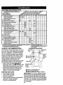
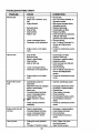
CUSTOMER RESPONSIBILITIES
FILL
IN DATES
AS YOU
COMPLETE
/__S
R EGU LARSE RVICE
_f'_.,/_d,_
_'__€.__
t,_ _
_
_'
_
_
_
R,_t_
O__.,_
SERVICE
DATES
Check Tire Pressure
T
R
Check Operator Presence
Interlock Systems
and
CheckforLooseFasteners
Sharpen/Replace
Lubrication
Check
Claan Battery and Terminals
Battery
Level
Check
Transaxle
Adjust
Blade
Adjust Motion
Drive Belt(s)
V's
Tension
Engine Oil Level
Engine
Claan Air Filter
?
Inspect
ClaanAir
II_s
_1_
V'
Oil
ll_l.2.a
Oil Filter
Engine
If
_:
Screen
Mufflar/Spark
Replace
Clean
COOling
Belt(s) Tension
E
N
v"
Arrestor
(If equipped)
Cooling
11_1.2
F_ns
Replace
Replace
Spark Plug
Air Filter Paper
Replace
Fuel Filter
1_2
_V'=
Cartridge
5. if equippedwfl_ adjustaJc4e
system.
6. Not r_Jired if _u_ped w_h maintenance-free bat_ry.
7. Tighten frorit rodepivot bolt ;o35 [t.-It_. rn_mun_
DO no_ove_ghte_.
3. _f equipped with oil fi;tef, change oil qweri 50 hours.
4 - Replace blmdes more often when mow_i_l in sandy soil.
RECOMMENDATIONS
The warranty on this tractor does not cover
items that have been subjected to operator
abuse or negligence. To receive full value
from the warranty, operator must maintain
tractor as instructed in this manual. Some
adjustments will need to be made periodically to properly maintain your tractor.
All adjustments in the Service and
Adjustments section of this manual should
be checked at least once each season.
• Once a year you should,=_pl,_,a the
spark plug, clean or replace _0r filter, and
check blades and belts for wear. A new
spark plug and clean air filter assure
proper air-fuel mixture and help your
engine run better and last longer.
BEFOREEACH
•
•
•
•
_l_
If
I. Change more oftenwhen operating under a hem,y load or In high ambie_ t_.
2. Se=vice more oftenwhen operating h3di_ or dusty cond_Tons,
GENERAL
V _
If
R
Change
(_7
Chart
0
Check
V_
Mower Blades
USE
Check engine oil level.
Check brake operation.
Check tire pressure.
Check operator presence and interlock
systems for proper operation.
• Check for loose fasteners.
LUBRICATION
CHART
Zerk
Zerk
Wheel
Bearing
Zerk
Bearinc
0 Engine
O
Clutch
Pivot(s)
:
:
i.
:
'
!
O SAE 30 or 10w30 Motor OIL
O General Purpose Grease
O Refer to Maintenance "Engine" Section
IMPORTANT:
Do not oil or grease the pivot
points which have special nylon bear-ings.
Viscous lubricants will attract dust and dirt
that will shorten the life of the self-lubricating
bearings. If you feel they must be lubricated,
use only a dry, powdered graphite type lubricant sparingly.
18
TRACTOR
Alwaysobservesafetyruleswhen performing
any maintenance.
BRAKE
OPERATION
If tractor requires more than six (6) feet
stopping distance at high speed in highest
gear, then brake must be adjusted. (See
_1-O ADJUST BRAKE" in the Service and
Adjustments
TIRES
section of this manual).
IMPORTANT: To ensure proper assembly,
center hole in blade must align with star
on mandrel assembly.
• Reassemble hex belt, lock washer and
flat washer in exact order as shown.
• Tighten bolt securely (27-35 Ft. Lbs.
torque).
IMPORTANT:
Blade bolt is grade 8 heat
treated.
Trailing
e Up
• Maintain proper air pressure in all tires
(See "PRODUCT SPECIFICATIONS"
section of this manual).
• Keep tires free of gasoline, oil, or insect
control chemicals which can harm robber.
Flat Washer
Lock
Hex Bolt(Grade 8)*
• Avoid stumps, stones, deep ruts, sharp
objects and other hazards that may
cause tire damage.
TO SHARPEN BLADE
NOTE: We do not recommend sharpening blade but if you do, be sure the blade
is balanced.
NOTE: To seal tire punctures and prevent
flat tires due to slow leaks, tire sealant
may be purchased from your local parts
dealer. 13re sealant also prevents tire dry
rot and corrosion.
OPERATOR
PRESENCE
Care should be taken to keep the blade
balanced. An unbalanced blade will cause
excessive vibration and eventual damage
to mower and engine.
• The blade can be sharpened with a file
or on a grinding wheel. Do not attempt
to sharpen while it is on the mower.
• To check blade balance, you will need a
5/8" diameter steel bolt, pin, or a cone
balancer. (When using a cone balancer,
follow the instructions supplied with balancer).
NOTE: Do not use a nail for balancing
blade. The lobes of the center hole may
appear to be centered, but are not.
• Slide blade onto an unthreeded portion
of the steel bolt or pin and hold the belt
or pin parallel with the ground. If blade
is balanced, it should remain in a horizontal position, if either end of the blade
moves downward, sharpen the heavy
end until the blade is balanced.
SYSTEM
Be sure that operator presence and interlock systems are working properly. If your
tractor does not function as described
below, repair the problem immediately.
• The engine should not start unless the
clutch/brake pedal is fully depressed
and attachment clutch control is in the
disengaged position.
• When the engine is running, any
attempt by the operator to leave the
seat without first setting the parking
brake should shut off the engine.
• When the engine is running and the
attachment clutch is engaged, any
attempt by the operator to leave the
seat-should shut off the engine.
• The attachment clutch should never
operate unless the o_Y_a_s
seat.
BLADE
Star
Washer"_
in the
Center Hole
CARE
For best results mower blades must be
kept sharp.
blades.
BLADE
Blade
Replace bent or damaged
5/8" Bolt
or Pin
REMOVAL
BATTERY
• Raise mower to highest position to allow
access to blades.
• Remove hex bolt, lock washer and fiat
washer securing blade.
• Install-new or resharpened blade with
trailing edge up towards deck as shown.
Your tractor has a battery charging system
which is sufficient for normal use.
However, periodic charging of the battery
with an automotive charger will extend its
life.
19
• Keep battery and terminals clean.
• Keep battery bolts tight.
• Keep small vent holes open.
• Recharge at 6-10 amperes for 1 hour.
NOTE: The original equipment battery on
your tractor is maintenance free. Do not
attempt to open or remove caps or covers.
Adding or checking level of electrolyte is
not necessary.
TO CLEAN BATTERY
LUBRICATION
Only use high quality detergent oil rated
with API service classification SF, SG or
SH. Select the oil's SAE viscosity grade
according to your expected operating temperature.
AND TERMINALS
Corrosion and dirt on the battery and terminals can cause the battery to "leak"
power.
• Remove terminal guard.
• Disconnect BLACK battery cable first
then RED battery cable and remove
battery from tractor.
• Rinse the battery with plain water and
dry.
• Clean terminals and battery cable ends
with wire brush until bright.
• Coat terminals with grease or petroleum
jelly.
• Reinstall battery (See"REPLACING
BATTERY" in the SERVICE AND
ADJUSTMENTS
section of this manual).
V-BELTS
Check V-belts for deterioration and wear
after 100 hours of operation and replace if
necessary. The belts are not adjustable.
Replace belts if they begin to slip from
wear.
TRANSAXLE
ENGINE
COOLING
The transmission fan and cooling fins
should be kept clean to assure proper
cooling.
Do not attempt to clean fan or transmission while engine is running or while the
transmission is hot.
• Inspect cooling fan to be sure fan
blades are intact and clean.
• Inspect cooling fins for,_tkt,-mj=_ss clippings and other materials. To prevent
damage to seals, do not use compressed air or high pressure sprayer to
clean cooling fins.
TRANSAXLE
PUMP FLUID
The transaxle was sealed at the factory
and fluid maintenance is not required for
the life of the transaxle. Should the
transaxle ever le_.k or require servicing,
contact your nearest authorized service
center/department.
NOTE: Although multi-viscosity oils
(5W30, 10W30 etc.) improve starting in
cold weather, these multi-viscosity oils will
result in increased oil consumption when
used above 32°F. Check your engine oil
level more frequently to avoid possible
engine damage from running low on oil.
Change the oil after every 25 hours of
operation or at least once a year if the
tractor is not used for 25 hours in one
year.
Check the crankcase oil level before starting the engine and after each eight (8)
hours of operation. Tighten oil fill cap/dipstick securely each time you check the oil
level.
TO CHANGE
ENGINE
OIL
Determine temperature range expected
before oil change. All oil must meet API
service classification SF, SG or SH.
• Be sure tractor is on level surface.
• Oil will drain more freely when warm.
• Catch oil in a suitable container.
• Remove oil fill cap/dipstick. Be careful
not to allow dirt to enter the engine
when changing oil.
• Remove drain plug.
• After oil has drained completely, replace
oil drain plug and tighten securely.
• Refill engine with oil through oil fill dipstick tube. Pour slowly. Do not overfill.
For approximate capacity see "PRODUCT SPECIFICATIONS"
section of this
manual.
• Use gauge on oil fill cap/dipstick for
checking level. Be sure dipstick cap is
tightened securely for accurate reading.
Keep oil at "FULL" line on dipstick.
Air Screen
Plug
Oil Fill
2O
CLEAN AIR SCREEN
Air screenmustbe keptfree of dirt and
chaffto preventenginedamagefrom overheating.Cleanwith a wire brushor compressedair to removedirt andstubbem
driedgumfibers.
AIR FILTER
ENGINE
COOLING
FINS
Remove any dust, dirt or oil from engine
cooling fins to prevent engine damage
from overheating. Air guide covers must
be removed. Remove side panels and
hood (See =TO REMOVE HOOD AND
GRILLASSEMBLY"
in the Service and Adjustments section of this manual).
Your engine will not run propedy using a
dirty air filter. Clean the foam pre-cteaner
after every 25 hours of operation or every
season. Service paper cartridge every
100 hours of operation or every season,
whichever occurs first.
Top Air Guid_
Service air cleaner more often under dusty
conditions.
Engine Cooling
• Remove knob(s) and cover.
TO SERVICE PRE-CLEANER
•
•
•
•
Slide foam pre-cleaner off cartridge.
Wash it in liquid detergent and water.
Squeeze it dry in a clean cloth.
Saturate it in engine oil. Wrap it in
clean, absorbent cloth and squeeze to
remove excess oil.
• If very dirty or damaged,
cleaner.
Air Guide Cover A
(Both Sides)
replace pre-
MUFFLER
Inspect and replace corroded muffler and
spark arrester (if equipped) as it could create a fire hazard and/or damage.
• Reinstall pre-cleaner over cartridge.
• Reinstall cover and secure with knob(s).
TO SERVICE CARTRIDGE
SPARK PLUGS
• Remove wing nuts and cartridge plate.
• Carefully remove cartridge to prevent
debris from entering carburetor.
• Clean cartridge by tapping gently on flat
surface. If very dirty or damaged,
replace cartridge.
• Reinstall cartridge plate, wing nuts, precleaner, cover and secure with knob(s).
IMPORTANT:
Petroleum solvents, such
as kerosene, are not to be used to clean
the cartridge. They may cause deterioration of the cartddge. Do not oil cartridge.
Do notuse pressurized air to clean or dry
cartridge.
Replace spark plugs at the beginning of
each mowing season or after every 100
hours of operation, whichever occurs first.
Spark plug type and gap setting are
shown in "PRODUCT SPECIFICATIONS"
section of this manual.
IN-LINE
The fuel filter should be replaced once
each season. If fuel filter becomes
.Cover
clogged, obstructing fuel flow to carburetor, replacement is required.
• With engine cool, remove filter and plug
fuel line sections.
Plate
• Place new fuel filter in position in fuel
line with arrow pointing towards carburetor.
• Be sure there are no fuel line leaks and
Wing
clamps are properly positioned..
• Immediately wipe up any spilled gasoline.
Foam Pre-
Air Screen_
FUEL FILTER
Cartiridge
21
Clamp
Clamp
Fuel Filter
CLEANING
• Clean engine, battery, seat, finish, etc.
of all foreign matter.
• Keep finished surfaces and wheels free
of all gasoline, oil, etc.
• Protect painted surfaces with automotive type wax.
We do not recommend using a garden
hose to clean your tractor unless the electrical system, muffler, air filter and carburetor are covered to keep water out. Water
in engine can result in a shortened engine
life.
_,CAUTION:
Before performing any service or adjustments:
• Depress clutch/brake pedal fully and set parking brake.
• Place motion control lever in neutral (N) position.
• Place attachment clutch in "DISENGAGED"
position.
• Turn ignition key "OFF" and remove key.
• Make sure the blades and all moving parts have completely stopped.
• Disconnect spark plug wire from spark plug and place wire where it cannot come
in contact with plug.
TO REMOVE
• Disconnect front links from deck by
removing retainer springs.
• Raise lift lever to raise suspension
arms. Slide mower out from under tractor.
IMPORTANT: If an attachment other than
the mower deck is to be mounted on the
tractor, remove the front links.
TO INSTALL MOWER
MOWER
Mower will be easier to remove from the
right side of tractor.
• Place attachment clutch in "DISENGAGED" position.
• Move attachment lift lever forward to
lower mower to its lowest position.
• Roll belt off engine pulley.
• Disconnect clutch red from clutch lever
• Raise attachment lift lever to its highest
position.
• Slide mower under tractor with dis-
by removing retainer spring.
• Disconnect anti-swaybar from chassis
bracket by removing retainer spring.
• Disconnect suspension arms from rear
deck brackets by removing retainer
springs.
charge guard to right side of tractor.
• Lower lift lever to its lowest position.
• Install mower in reverse order of
removal instructions.
ctutct
Retainer
Suspension
Arms
Pulley
Front
Link
(Both Sides)
Retainer
(Both Sides)
Spring
AnU-Swaybaf
22
TO LEVEL MOWER
HOUSING
Adjust the mower while tractor is parked
on level ground or driveway. Make sure
tires are properly inflated (See =PRODUCT SPECIFICATIONS").
If tires are
over or underinflated, you will not propedy
adjust your mower.
SIDE-TO-SIDE
ADJUSTMENT
• Raise mower to its highest position.
• At the midpoint of both sides of mower,
measure height from bottom edge of
mower to ground. Distance =A" on both
sides of mower should be the same or
within 1/4" of each other.
• If adjustment is necessary, make adjustment on one side of mower only.
• To raise one side of mower, tighten lift
link adjustment nut on that side.
• To lower one side of mower, loosen lift
• Before making any necessary adjustments, check that both front links are
equal in length. Both links should be
approximately 10-3/8".
• If links are not equal in length, adjust
one link to same length as other link.
• To lower front of mower loosen nut =E"
on both front links an equal number of
tums.
• When distance =D" is 1/8" to 1/2" lower
at front than rear, tighten nuts "P
against trunnion on both front links.
• To raise front of mower, loosen nut "P
from trunnion on both front links.
Tighten nut =E" on both front links an
equal number of turns.
• When distance =D" is 1/8" to 1/2" lower
at front than rear, tighten nut =P against
trunnion on both front links.
• Recheck side-to-side adjustment.
link adjustment nut on that side.
NOTE:
Each full turn of adjustment nut
will change mower height about 1/8".
• Recheck measurements
Bottom Edge of
after adjusting,
Bottom Edge of
Both Front Links Should be Equal in Length
Mower_r_und
"_'-'_J
Ground Line
_'"'_'T
Suspension
Arm
Nut =P
Lift Link Adjustment Nut
FRONT-TO-BACK
ADJUSTMENT
IMPORTANT:
Deck must be level side-toside.
ment
front
level
If the following fr_t-t_ack
adjustis necessary, be si.ire to adjust both
links equally so mower will stay
side-to-side.
Front Links
TO REPLACE
MOWER
BLADE
DRIVE
To obtain the best cutting results, the
mower housing should be adjusted so that
the front is approximately 1/8" to 1/2"
lower than the rear when the mower is in
BELT (See Illustration Next Page)
The mower blade drive belt may be
replaced without tools. Park the tractor on
level surface. Engage parking brake.
its highest position.
Check adjustment on right side of tractor.
Measure distance =D" directly in front and
behind the mandrel at bottom edge of
mo_er housing as shown,
BELT REMOVAL• Remove mower from tractor (See "TO
REMOVE MOWER" in this section of
this manual).
• Work belt off both mandrel
idler pulleys.
23
pulleys and
• Pullbelt awayfrommower.
BELTINSTALLATION
-
• Make sure belt is in all pulley grooves
and inside all belt guides.
• Install mower in reverse order of
removal instructions.
• Install new belt in reverse order of
removal.
Idler
Mandrel
Pulley
Pulleys
Mandrel
Pulley
TO ADJUST
BRAKE
TO REPLACE
Your tractor is equipped with an adjustable
brake system which is mounted on the
side of the transaxle.
If tractor requires more than six (6) feet
stopping distance at high speed in highest
gear, then brake must be adjusted.
• Depress clutch/brake pedal and engage
parking brake.
• Measure distance between brake operating arm and nut "A" on brake rod.
• If distance is other than 1-9/16", loosen
jam nut and turn nut "A" until distance
becomes 1-9/16". Retighten jam nut
against nut "A",
• Road test tractor for proper stopping
distance as stated above. Readjust if
necessary. If Stopping distance is still
greater than six (6) feet in highest gear,
further maintenance is necessary.
Contact your nearest authorized service center/department.
_N
N
Jam
%_king
Brake
=Engaged"
Do Not touch this nut. If further brake adjustment is necessary contact your nearest authorized service center/depadment
24
DRIVE
BELT
• Remove mower (See "TO REMOVE
MOWER" in this section of this manual.)
• Remove belt from stationary idler and
clutching idler.
• Pull belt slack toward rear of tractor.
Carefully remove belt upwards from
transmission input pulley and over cooling fan blades.
• Pull belt toward front of tractor and "
remove downward from around engine
pulley.
• Install new belt by reversing above procedure.
Engine.________
Pulley
Clutching Idler
Stationary Idler
ut
ut =A"
AITR
MOTION
Park the tractor on level surface. Engage
parking brake. For assistance, there is a
belt installation guide decal on bottom side
of left footrest.
Transmission
Input Pulley_
TO ADJUSTMOTIONCONTROLLEVER
The motioncontrolleverhas beenpreset
at the factory and adjustment should not
TO REMOVE
be rlecessary.
If for any reason the motion control lever
will hot hold its position while at a selected
speed, it may be adjusted at the friction
pack located on the right side of transmission.
• Park tractor on level surface. Stop tractor by turning ignition key to "OFF" position, and engage parking brake.
• Adjust motion control lever by tightening
adjustment Iocknut one half (1/2) tum.
NOTE: If for any reason the effort to
move the motion control lever becomes
too excessive, reverse the above adjustment procedure by loosening Iocknut 1/4
to 1/2 turn.
Road test tractor after adjustment and
repeat procedure if necessary.
TRANSMISSION
MENT
WHEEL
FOR REPAIRS
• Block up axle securely.
• Remove axle cover, retaining ring and
washers to allow wheel removal (rear
wheel contains a square key - Do not
lose).
• Repair tire and reassemble.
• On rear wheels only: align grooves in
rear wheel hub and axle. Insert square
key.
• Replace washers and snap retaining
ring securely in axle groove.
• Replace axle cover.
NOTE: To seal tire punctures and prevent
flat tires due to slow leaks, tire sealant
may be purchased from your local parts
dealer. Tire sealant also prevents tire dry
rot and corrosion.
Washers
Retaining _,_
A
REMOVAL/REPLACE-
Should your transmission require removal
for service or replacement, it should be
purged after reinstallation and before
operating the tractor. See "PURGE
TRANSMISSION"
in the Operation section
of this manual.
Axle Cover
(Rear Wheel Only)
TO START ENGINE WITH A WEAK
BATTERY
.&,CAUTION:
Lead-acid batteries generate explosive gases. Keep sparks, flame
and smoking materials away from batteries. Always wear eye protection when
around batteries.
If your battery is too weak to start the
engine, it should be recharged. (See
"BAI-IERY" in the MAINTENANCE
sec-
TO ADJUST
MENT
STEERING
WHEEL ALIGN-
If steering wheel crossbars are not horizontal (left to right) when wheels are positioned straight forward, remove steering
wheel and reassemble per instructions in
the Assembly section of this manual.
FRONT WHEEL TOE-IN/CAMBER
The front wheel toe-in and camber are not
adjustable on your tractor. If damage has
occurred to affect the front wheel toe-in or.
camber, contact your nearest authorized
service center/department.
25
tion of this manual).
If "jumper cables" are used for emergency
starting, follow this procedure:
IMPORTANT:
Your tractor Is equipped
with a 12 volt negative grounded system.
The other vehicle must also be a 12 volt
negative grounded system. Do not use
your tractor battery to start other vehicles.
TO ATTACH JUMPER CABLES • Connect each end of the RED cable to
the POSITIVE (+) terminal of each battery, taking care not to short against
chassis.
• Connect one end of the BLACK cable to
the NEGATIVE (-) terminal of fully
charged battery.
• Connect the other end of the BLACK
cable to good CHASSIS GROUND,
away from fuel tank and battery.
TO REPLACE HEADLIGHT
BULB
• Raise hood.
• Pull bulb holder out of the hole in the
TO REMOVE CABLES, REVERSE
ORDER• BLACK cable first from chassis and
backside of the grill.
• Replace bulb in holder and push bulb
holder securely back into the hole in the
backside of the grill.
• Close hood.
INTERLOCKS
AND RELAYS
then from the fully charged battery.
• RED cable last from both batteries.
"Positive" (+)
REPLACING
Loose or damaged wiring may cause your
tractor to run poorly, stop running, or prevent it from starting.
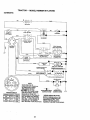
• Check wiring. See electrical wiring diagram in the Repair Parts section
TO REPLACE FUSE
"Negative" (-)
Replace with 30 amp automotive-type
plug-in fuse. The fuse holder is located
behind the dash.
TO REMOVE HOOD AND GRILL ASSEMBLY
• Raise hood.
• Unsnap headlight wire connector.
• Stand in front of tractor. Grasp hood at
sides, tilt toward engine and lift off of
tractor.
• To replace, reverse above procedures.
BATTERY
ACAUTION:
Do not short battery terminals by allowing a wrench or any other
object to contact both terminals at the
same time. Before connecting battery,
remove metal bracelets, wristwatch
bands,rings,etc.
Positive terminal must be connected first
/Hood
I _,_
/._/_
to prevent sparking from accidental
grounding.
• Lift hood to raised position.
• Remove terminal guard.
• Disconnect BLACK battery cable then
RED battery cable and carefully remove
battery from tractor.
• Install new battery with terminals in
same position as 01d battery.
• Reinstaltterminal guard.
• First connect RED battery cable to positive (+) battery terminal with hex bolt
and keps nut as shown. Tighten securely.
• Connect BLACK grounding cable to
negative (-) battery terdt_aRl_ffh
remaining hex bolt and keps nut.
"13ghtensecurely.
• Close terminal access doors.
• Close hood.
. Hex
Keps Nut
Bolt
Terminal
Access
:f_:;_"
_
Connector
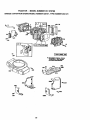
ENGINE
Maintenance, repair, or replacement of the
emission control devices and systems,
which are being done at the customers
expense, may be performed by any nonread engine repair establishment or individual. Warranty repairs must be performed by an authorized engine manufacturer's service outlet.
TO ADJUST THROTTLE CONTROL
CABLE
The throttle control has been preset at the
factory and adjustment should not be necessary. Check adjustment as described
below before loosening cable. If adjustment is necessary, proceed as follows:
• With engine not running, move throttle
control lever to fast position.
• Check that swivel is against side of
quarter cimle. If it is not, loosen cable
clamp screw and pull cable back until
swivel is against quarter circle. Tighten
Positive
pCable
Terminal
Headlight
/Wire
Negative
(Black) Cable
cable clamp screw securely.
26
TO ADJUSTCHOKECONTROL
The chokecontrolhas beenpresetat
• With engine off turn idle mixture screw
in (clockwise) closing itfinger tight and
then tum out (countemlockwise) 1-1/4
to 1-112 turns.
the
factory and adjustment should not be necessary. Check adjustment as described
below before loosening cable. If adjustment is necessary, proceed as follows:
• With engine not running, move choke
control (located on dash panel) to full
choke position.
• Remove air cleaner cover, filter and cartridge plate to expose carburetor choke
(see "AIR FILTER" in the Customer
Responsibilities section of this manual).
• Choke should be closed. If it is not,
loosen casing clamp screw and move
choke cable until choke is completely
closed. Tighten casing clamp screw securely.
• Reassemble air cleaner.
FINAL SETTING
• Start engine and allow to warm for five
minutes. Make final adjustments with
engine running and shift/motion control
lever in neutral (N) position.
• With throttle control lever in slow position, hold throttle lever against idle
speed screw and adjust idle speed
screw to obtain 1200 to 1400 RPM.
• While still holding throttle lever against
idle speed screw, turn idle mixture
screw in (clockwise) until engine begins
to die and then turn out (counterclockwise) until engine runs rough. Tum
screw to a point midway between those
two positions.
• Continue to hold throttle lever against
idle speed screw and adjust idle speed
screw to obtain 900 to 1200 RPM. Release throttle lever.
Clamp
Quarter Cimle
ACCELERATION
TEST
• Move throttle control lever from slow to
Casing
Clamp
Choke
Lever
TO ADJUSTCARBURETOR
The carburetor has been preset at the factory and adjustment should not be necessary. However, minor adjustment may be
required to compensate for differences in
fuel, temperature, altitude or load. If the
carburetor does need adjustment, proceed
as follows:
In general, turning the mixture screw in
(clockwise) decreases_a're_J_pply of fuel to
the engine giving a leaner fuel/air mixture.
Tuming the mixture screw out (counterclockwise) increases the supply of fuel to
the engine giving a richer fuel/air mixture.
IMPORTANT:
Damage to the needles and
the seats in carburetor may result it screw
is turned in too tight.
PRELIMINARY
fast position. If engine hesitates or dies,
turn idle mixture screw out (counterclockwise) 1/8 turn. Repeat test and
continue to adjust, if necessary, until
engine accelerates smoothly.
High speed stop is factory adjusted. Do
not adjust - damage may result.
IMPORTANT:
Never tamper with the
engine governor, which is factory set for
proper engine speed. Overspeeding the
engine above the factory high speed setting can be dangerous. If you think the
engine-governed high speed needs
adjusting, contact your nearest authorized
service center/department, which has
proper equipment and experience to make
any necessary adjustments.
Idle Speed
Throttle
Lever-...
ldle Speed
SE'I-I-ING
Screw
le Mixture
rew
• Be sure you have a clean air filter, and
the throttle control cable and choke are
adjusted properly
Idle Mixture
(see above).
Lever
27
....................
Immediately prepare your tractor for storage at the end of the season or if the tractor will not be used for 30 days or more.
,ACAUTION:
Never store the tractor with
gasoline in the tank inside a building
where fumes may reach an open flame or
spark. Allow the engine to cool before storing in any enclosure.
TRACTOR
Remove mower from tractor for winter
storage. This will allow you to clean it thoroughly. Remove all dirt, grease, leaves,
etc. Store in a clean, dry area.
• Clean entire tractor (See "CLEANING" in
the Maintenance section of this manual).
• Inspect and replace belts, if necessary
(See belt replacement instructions in the
Service and Adjustments section of this
manual).
• Lubricate as shown in the Maintenance
section of this manual.
• Be sure that all nuts, bolts and screws
are securely fastened. Inspect moving
parts for damage, breakage and wear.
Replace if necessary.
• Touch up all rusted or chipped paint surfaces; sand lightly before painting.
fuels (called gasohol or using ethanol or
methanol) can attract moisture which leads
to separation and formation of acids during
storage. Acidic gas can damage the fuel
system of an engine while in storage.
Drain the fuel tank.
• Start the engine and let it run until the
fuel lines and carburetor are empty.
• Never use engine or carburetor cleaner
products in the fuel tank or permanent
damage may occur.
• Use fresh fuel next season.
NOTE: Fuel stabilizer is an acceptable
alternative in minimizing the formation of
fuel gum deposits during storage. Add stabilizer to gasoline in fuel tank or storage
container. Always follow the mix ratio
found on stabilizer container. Run engine
at least 10 minutes after adding stabilizer
to allow the stabilizer to reach the carburetor. Do not drain the gas tank and carburetor if using fuel stabilizer.
ENGINE
OIL
Drain oil (with engine warm) and replace
with clean engine oil. (See "ENGINE" in
the Maintenance section of this manual).
CYLINDER(S)
• Remove spark plug(s).
• Pour one ounce of oil through spark plug
hole(s) into cylinder(s).
• Turn ignition key to "START" position for
a few seconds to distribute oil.
BATTERY
• Fully charge the battery for storage.
• After a period of time in storage, battery
may require recharging.
• To help prevent corrosion and power
leakage during long periods of storage,
battery cables should be disconnected
and battery cleaned thoroughly (see "TO
CLEAN BATTERY AND TERMINALS" in
the Maintenance section of this manual).
• After cleaning, leave cables disconnected and place cables where they cannot
come in contact with battS,ry_ffninals.
• If battery is removed from tractor for
storage, do not store battery directly on
concrete or damp surfaces.
• Replace with new spark plug(s).
OTHER
• Do not store gasoline from one season
to another.
• Replace your gasoline can if it starts to
rust. Rust and/or dirt in your gasoline will
cause problems.
• If possible, store your tractor indoors
and cover it to give protection from dust
and dirt.
• Cover your tractor with a suitable protective cover that does not retain moisture.
ENGINE
Do not use plastic. Plastic cannot
breathe, which allows condensation to
form and cause your tractor to rust.
IMPORTANT:
Never cover tractor while
FUEL SYSTEM
IMPORTANT: It is important to prevent
gum deposits from forming in essential fuel
system parts such as carburetor, fuel filter,
!uel hose, or tank during storage. Also,
_xperience indicates that alcohol blended
engine and exhaust areas are still warm.
28
TROUBLESHOOTING
CHART
PROBLEM
Will not start
CAUSE
CORRECTION
• Out of fuel.
• Engine not =CHOKED" prop• Engine flooded.
•
•
•
-
Bad spark plug.
Dirty air filter.
Dirty fuel filter.
Water in fuel:
• Engine valves out of adjustmerit.
gasoline and replace fuel filter.
• Check all wiring.
* See "To Adjust Carburetor" in
Service and Adjustments
section.
• Contact an authorized service
center.
•
•
•
•
•
•
•
•
•
•
• Loose or damaged wiring.
• Carburetor out of adjustmenL
Hard to start
Dirty air filter.
Bad spark plug.
Weak or dead battery.
Dirty fuel filter.
Stale or dirty fuel.
• Loose or damaged wiring.
• Carburetor out of adjustment.
• Engine valves out of adjustmenL
Engine will not turn
over
• Fill fuel tank.
• See "TO START ENGINE" in
Operation section.
• Wait several minutes before
attempting to start.
• Replace spark plug.
• Clean/replace air filter.
• Replace fuel tilter.
• Drain fuel tank and carburetor,
refill tank wi_ fresh
• Clutch/brake pedal not
depressed.
• Attachment dutch is engaged.
• Weak or dead battery.
• Blown fuse.
Clean/replace air filter.
Replace spark plug.
Recharge or replace battery.
Replace fuel tilter.
Drain fuel tank and refill with
fresh gasoline.
• Check all wiring.
• See "To Adjust Carburetor" in
Service and Adjustments
secfion.
• Contact an authorized service
center.
Depress clutchrbrake pedal.
• Faulty operator presence
s_tch(es).
Disengage attachment clutch.
Recharge or replace battery.
Replace fuse.
Clean battery terminals.
Check all wiring.
Check/replace ignitionswitch.
Check/replace solenoid or
starter.
• Contact an authorized service
center.
Engine dicks but will
not start
•
•
•
•
•
•
•
•
Loss of power
* Cutting too much grass/too
fast.
• Throttle !n "CHOKE" position.
• Corroded battery terminals.
• Loose or damaged wiring.
• Faulty ignitionswitch.
F_aultysolenoid or starter.
Weak or dead battery.
Corroded battery terminals.
Loose or damaged wiring.
Faulty solenoid or starter.
29
•
•
•
•
•
•
•
Recharge or replace battery.
Clean battery terminals.
Check all wiring.
Check/replace solenoid or
starter.
• Set in =Higher Cut" position/reduce.speed.
• Adjust throttle control.
TROUBLESHOOTING
CHART
PROBLEM
CAUSE
CORRECTION
Loss of power (coot'd)
• Build-up of grass, leaves and
trash under mower.
• Dirty air filter.
• Low oil level/dirty oil.
• Faulty spark plug.
• Clean underside of mower hous-
• Dirty fuel filter.
• Stale or dirty fuel.
• Water in fuel.
• Spark plug wire loose.
•
•
•
•
Excessive vibration
Dirty engine air screen/fins.
Dirty/clogged muffler.
Loose or damaged wiring.
Carburetor out of adjustment.
• Engine valves out of adjustment.
• Worn, bent or loose blade.
• Bent blade mandrel.
• Loose/damaged part(s).
Engine continues to
run when operator
leaves seat with attachment clutch
engaged
Poor cut - uneven
• Faulty operator-safety presence control system.
• Worn, bent or loose blade.
• Mower deck not level.
Mower blades will not
rotate
Poor grass discharge
• Buildup of grass, leaves, and
trash under mower.
• Bent blade mandrel.
• Clogged mower deck vent
holes from buildup of
_r-_-_ievas,
and trash
around mandrels.
• Obstruction in clutch mechanism.
ing.
• Clean/replace air filter.
I • Check oil level/change oil.
• Clean and regap or change
spark plug.
• Replace fuel filter.
• Drain fuel tank and refill with
fresh gasoline.
• Drain fuel tank and carburetor,
refill tank with fresh gasoline and
replace fuel filter.
• Connect and tighten spark plug
wire.
•
•
•
•
Clean engine air screen/fins.
Claan/replace muffler.
Check all wiring.
See "ToAdjust Carburetor' in
Service and Adjustments
section.
• Contact an authorized service
center.
• Replace blade. Tighten blade
bolt.
• Replace blade mandrel.
• Tighten loose part(s). Replace
damaged parts.
• Check widng, switches and connections, if not
corrected, contact an authorized
service canted
department.
• Replace blade. Tighten blade
bolt.
• Level mower deck.
• Clean underside of mower housing.
• Replace blade mandrel.
• Clean around mandrels to open
vent holes.
• Remove obstruction.
• Worn/damaged mower ddve
belL
• Replace mower drive bell
• Frozen idler pulley.
• Frozen blade mandrel.
• Engine speed too slow.
• Replace idler pulley.
• Replace blade mandrel.
• Place throttle control in "FAST"
position.
• Shift to slower speed,
• Allow grass to dry before mowing.-
• Travel speed too fast.
• Wet grass.
30
TROUBLESHOOTIN!; CHART
PROBLEM
CAUSE
Poor grass discharge
(cont'd)
CORRECTION
• Mower deck not level.
• Low/uneven tire air pressure.
• Worn, bent or loose blade.
• Buildup of grass, leaves and
trash under mower.
• Mower ddve belt worn.
I • Blades improperly installed.
I*
Improper blades used.
I • Clogged mower deck vent
Headlight(s) not
holes from buildup of
grass, leaves, and trash
around mandrels.
• Switch is "OFF",
• Check tires for proper air pressure.
• Replace/sharpen blade. Tighten
blade bolt.
• Clean underside of mower housing.
• Replace mower ddvebelt.
• Reinstall blades sharp edge
down.
• Replace with blades listed in this
manual.
• Clean around mandrels to open
vent holes.
• Turn switch "ON".
working (if so
equipped)
•
•
•
•
Battery will not
charge
• Bad battery cell(s).
• Poor cable connections.
• Replace regulator.
Loss of drive
• Faulty regulator (if so
equipped).
• Faulty alternator.
• Freewheel control in "disengaged" position.
• Motion drive belt worn, damaged or broken.
• Air trapped in transmission
during shipment
or servicin,q.
• Engine throttle control not set
at "SLOW" position for 30
seconds before stopping
engine.
"engaged" position.
• Replace motion drive belt.
Engine "backfires"
when turning engine
"OFF'
Bulb(s) burned out.
Faulty light switch.
Loose or damaged wiring.
Blown fuse.
• Level mower deck.
31
•
•
•
•
•
•
Replace bulb(s).
Check/replace light switch.
Check wiringand connections.
Replace fuse.
Replace battery.
Check/clean all connections.
• Replace alternator.
• Place freewheel control in
Purge transmission.
•
Move throttle control to "SLOW"
position and allow to idle for 30
seconds before stopping engine.
SERVICE NOTES
32
TRACTOR - - MODEL NUMBER 917.270780
SCHEMATIC
L
BATFERY
RED
FUSE3OAMP.
STARTER
_J_K
WHITE
'©
I
' O-+--
t
L
J
CLUTCH/BRAKE
(PEDALUP)
SEAT
IGNITION
SWITCH
(NOT
SWITCH
OCCUPIED)
t
I
8LACK
GROUNDING
CONNECTOR
(OPTIONAL)
,GN,T,ON
I----oSPA
LUGe-UNIT
J(2
PLUGS ON
TWIN CYL ENGINES)
C_A_
SY_
3 AMP DC o _
LR_41_NG
_Po_
RPM
21 VOLI_ AC k_hLO 3_O #_M
(CHARGINGSYSTi_M DISCONNECTED
SYSTIE M _
I
j
HEADLIGHTS
IGNITION
SWITCH
NOTE
YOUR TRACTOR IS
EQUIPPED WITH A SPECIAL
ALTERNATOR
SYSTEM.
THE LIGHTS ARE NOT
_TED
TO THE
BATTERY, BUT HAVE THEIR
OWN ELECTRICAL SOURCE.
BECAUSE OF THIS, THE
BRIGHTNESS OF THE LIGHTS
WILL CHANGE WITH ENGINE
SPEED. AT IDLE THE LIGHTS
WILL DIM. AS THE ENGINE IS
SPEEDED UP, THE LIGHTS
NON*REMOVABLE
CONNECTIONS
WILL BECOME THEIR BRIGHTEST.
33
REMOVABLE
CONNECTIONS
/_
WIRING INSULATED CLIPS
NOTE: IF WIRING INSULATED
CLIPS WERE REMOVED FOR
SERVICING OF UNIT, THEY
SHOULD BE REPLACED TO
PROPERLY SECURE YOUR WIRING.
TRACTOR
- - MODEL
NUMBER
917.270780
ELECTRICAL
21
26
I
I
:34
TRACTOR
- - MODEL
NUMBER
ELECTRICAL
KEY
PART
NO.
NO.
DESCRIPTION
163465
74760412
7603J
145211
150109
145769
153664
STD551125
73350400
147430
41523
4799J
146148
108824X
73510400
145491
121305X
140301
124211X
141226
109310X
156442
71110408
131563
145673
73640400
121433X
141940
17490508
140413
Battery
Boll Hex 1/4-20x3/4
Tray, BaMen/
Bolt, Btr Front 1/4-20 x 7-1/2
HolddownBattery Front Mount
Nut, Push NylonBattery Front 1/4
Switch InterlockPush-In
Washer, Lock 1/4
Nut, Hex, Jam 1/4-20
Harness, LightSocket (w/4152J)
Light Bulb
Cable, Battery
Cable, Battery
Fuse
Nut Keps Hex 1/'4-20Unc
Cable, Ground
Switch, Seat
Switch, Ignition4 Position
Nut, Ignition
Cover, IgnitionSwitch
Key, Molded, Craftsman
Harness, Ignition
Bolt BIKFin Hex 1/4-20 UNC x 1/2
Cover, Terminal
Solonoid
Nut Keps Blk Hex 1/4-20 UNC
Ammeter Roctangular6 Amp
ProtectionWire Loop (Hour Meter)
Screw Thdrol 5/16-18 x 1/2
Harness Engine B&SKec Dual
1
2
8
10
11
12
16
19
20
21
22
24
25
26
27
28
29
30
31
32
33
40
41
42
43
44
45
52
55
70
NOTE: All componentdimensionsgiven in U.S. inches
1 inch = 25.4 mm
35
917.270780
TRACTOR
- - MODEL
NUMBER
917.270780
CHASSIS AND ENCLOSURES
28
58
12
31
14
6O
3
74
14
3
38_
39
36
TRACTOR
- - MODEL
NUMBER
917.270780
CHASSIS AND ENCLOSURES
KEY
PART
NO.
NO.
1
2
3
4
5
9
10
11
12
13
14
17
18
20
23
25
26
28
29
30
31
37
38
39
51
52
53
54
55
57
58
60
64
74
140
142
143
144
145
--
160392
140356
17490612
STD551025
155272
161917X013
STD533710
155927
145660
155934X010
17490608
144983X558
126938)(
156437
124028X
19131312
STD541437
145198X558
155217X599
151287X558
139976
17490508
139886
139887
73800400
19091416
145201
161464
145202
STD552507
140547
72140606
154798
STD541437
158418
165867
154966
154207
156524
DESCRIPTION
Chassis
Drawbar
Screw, Thd., Roll. 3/8-16 x 3/4 Type Tf
Washer 13/32 x 3/4 x 16 Gauge
BumperHood/Dash
Dash, Silk.screened
Bolt, Carriage 3/8-16 x 1
Panel, Dash, LH
Clip "SnnermanGrille P/L
Panel, Dash, RH
Screw, Thd. Roll. 3/8-16 x 1/2 Type TI"
Hood Assembly
Bumber Hood
Ptate Mtg Buttery Fuel Tank
Bushing,Snap, Nylon, Fuel Line
Washer 13/32 x 13/16 x 12 Gauge
Locknut,Hex, with Insert 3/8-16 UNC
Grille,W/Clips MS-558
Lens, Grille
Feeder/Footrest
Bracket, FenderiSuppert
Screw, Thdrol. 5/16-18 x 1/2 TYT
Pivot BracketAssembly,LH, Mower, Rear
Pivot BrecketAssembly,RH, Mower, Rear
Nut Look W/Insert 1/4 - 20 UNC
Washer 9/32 X 7/8 X 16 Ga.
BracketGrille PickoffLH
Screw, Hex Wsnd #6-18 x 7/8
BracketGrille PickoffRH
BoltFinHex 1/4 -20 UNC X.75
Air Duct P/L 18HP B&S Opp. Twin
BoltRdhd Sqnk 3/8-16 UNC x 3/4
Dash Lower STLT
NutCrowniock 3/8-16 UNC
BracketSuspensionFront
Plate ReinforcementSTLT
Bracket Swaybar Chassis
Bracket FootrestSTLT
Rod Pivot Chassis/Hood
Plug Bm BIk .359 Dia CMnI
NOTE: Allcomponent dimensionsgiven in U.S. inches
1 inch= 25.4 mm
37
TRACTOR
- - MODEL
NUMBER
917.270780
GROUND DRIVE
57
J
116
J
61
64
50
149
150
71_1619
27.._"
147_
10
_
150
4
1
47
9!521
_
151
.146
27
55
77
100
38
106
7
TRACTOR
- - MODEL
NUMBER
917,270780
GROUND DRIVE
KEY
NO
1
PART
NO.
150071
2
3
8
10
16
142431
143995
154792
STD561210
STD541431
18
STD523710
19
STD541437
21
22
24
25
26
27
28
29
30
32
34
35
36
37
38
39
40
41
42
130564
145627
73350600
106888X
STD551037
STD561210
145204
124236X
130807
74760512
155071
120183X
19211616
1572H
131494
STD523727
4470J
165838
19131312
43
47
48
49
50
51
52
53
55
56
57
59
61
19111012
127783
154407
123205X
STD523715
STD541437
STD541431
105710X
105709)(
STD523712
140294
140312
17490612
62
63
64
8883R
140186
71170764
KEY
NO.
DESCRIPTION
PART
NO.
Traneaxle ( See Breakdown)
Hydro Gear Model No. 3190650
Spring, Return, Brake
Pulley,Traneaxle
Rod Shift Fender STLT
PinCotter 1/8x I CAD
NutLockHexW/Ins 5/16-18
Unc
BoltFin Hex 3/8-16 Unc x I
Gr 5
NutLockHexW/Wsh 3/8-16
Unc
65
66
70
71
72
73
74
75
STD551143
154778
134683
140158
19132912
156347
121199X
121749X
76
77
78
STD581075
123583X
121748X
Knob, Deluxe 1/2-13
ROd,Brake Hydro
Nut, Hex Jam 3/8-16 Unc
Spring, Brake ROd
Washer
Pin Cotter 1/8 x 3/4 CAD.
ROd, ParkingBrake
Cap, Parking Brake
Bracket,Transaxle
BoltHex Hd 5/16-18 Unc x 3/4
Shaft, FootPedal
Bearing, Nylon
Washer
Pin, Roll
Pulley,Idler, Flat
Bolt
Spacer, Split
Keeper,Belt Idler
Washer 13/32 x 13/16 x 12
Gauge
Washer 11/32xs/8x12Ga.
Pulley,Idler, V-Groove
BellcrankClutchGrnd Drv STL
Retainer,Belt
Bolt
Nut Crownlock 3/8-16 UNC
Nut, Crownlook 5/16-18 Unc
Unk, Clutch
Spring,Return, Clutch
BoltHe:_8-_-1/4
V-Belt, GF¢_Jund
Drive
Keeper,CenterSpan
Screw Thdrol, 3/6-16 x 3/4 Ty.
TT
Cover, Pedal
Pulley,Engine
Bolt Hex 7/16-20 x 4 Gr 5
81
156046
82
83
84
86
87
88
89
90
_3
94
95
96
97
123782X
19171216
161901
157480
19212016
12000008
164890X428
124346X
142564
140462
144643
4497H
140469
98
100
102
73510600
19111216
141322
103
73940800
104
105
106
140156
71070516
74780520
116
144
145
146
147
148
149
150
151
72110610
19111016
74490540
74490536
74480524
159103
122052X
150935
19133210
DESCRIPTION
Washer
Keeper Bolt Engine Hydro
Guide Bolt RH Engine
Strop Torque Lh Hydro 18/20" T
Washer 13/32 x 1-1/4 x 12 Ga.
Strap Torque Rh Hydro 0650
Spacer, Split
Washer 25/32 x 1-1/4 x 16
Gauge
E-Ring
Key, Square
Washer 25/32 x 1-5/8 x 16
Gauge
ShaftAsm. Cross Hydro 20"
"Rres
SpringTorsion T/A
Washer 17/32 x 3/4 x 16 Ga.
Rod, Tie Hydro 20" Tires
Bushing
Washer 21/32 x 1-1/4 x 16 Ga
Ring }(lip #5304-62
Console, Shift
Nut Selt*ThdWsh-hd 1/4 Zinc
Line Fuel Hydro 4"
Fan, Hydro 7"
ControlBypass Hydro 20" Tires
Retainer Spring 1"Zinc'Cad
Keeper Bolt Rh Hydro 0750
18/20"
Nut Keps Hex 3/8-16 Unc
Washer 11/32 x 3/4 x 16 Ga
Washer Bellville 501D x
150D
Nut Hex Jam Toplock 1/4-20
Unf
Arm, ControlHydro
Screw Cap Hex 5/16 x 18 x 1
Bolt Fin Hex 5/16-18 Unc x 1114
BoltCart. 3/8-16 x 1.25
Washer 11/32 x 5/8 x 16 Ga.
BoltHex Flghd5/16-18 Gr. 5
Bolt Hex Flghd 5/16-18 x 2-1/4
Belt Hex Flghd5/16-18 x 1-1/2
Spacer
Spacer Retainer PM Mower
BushingNylon Collared
Washer 13/32 x 2 x 10 Ga.
NOTE: Allcomponentdimensionsgiven in U.S. inches
1 inch= 25A mm
39
TRACTOR
- - MODEL
NUMBER
917.270780
STEERING ASSEMBLY
"----_-€,3
t
......
.,-__.._j
s
_41
,
,'------42
i
I
44
47
$&
4O
TRACTOR
STEERING ASSEMBLY
KEY
NO.
PART
NO.
1
2
3
4
5
6
7
8
9
10
11
13
15
17
18
19
20
22
23
25
26
27
28
29
30
32
36
37
38
39
40
41
42
43
44
46
47
51
54
62
63
139768
154427
156483
157473
6266H
121748X
19272016
12000029
3366R
156438
STD551137
154779
73901000
156546
57079
124035)(
126684X
71200410
127501
154406
126847X
136874
19131416
17490612
STD561210
130465
155099
152927
139769
19133808
STD541537
100711L
145054
121749X
153720
121232X
6855M
73800500
74780520
156594
74780616
66
67
68
154404
74781044
154429
65 ltJ ttBo
- - MODEL
NUMBER
917.270780
DESCRIPTION
Steering Wheel
FrontAxle Assembly
Spindle Assembly,LH.
SpiedleAssembly,R.H.
Beadng, Race, Thrust, Hardened
Washer 25/32 x 1-5/8 x 16 Gauge
Washer 27/32 x 1-1/4 x 16 Gauge
Ring, Klip
Bearing, Steering Column
Unk, Drag
Washer, Lock
Spacer, Bearing, FrontAxle
Nut, Lock, Flange 5/8-11 UNC
Shaft Assembly,Steering
Washer, Thrust .515 x .750 x .033
Support, Shaft
Washer, Shim 1/4 x 5/8 x .062
Screw Hex Socket 1/4-20 x 5/8
Pit, nan Shaft Assembly
Bracket, Steering
Bushing, Link, Drag
Gear, Sector
Washer 13/32 x 7/8 x 16 Gauge
Screw, Thd., Roll. 3/8-16 x 3/4
Pin
Rod, "Re
Bushing, Steering
Screw'lT #10-32 x 5 x 3/8 Flange
Insert, Steering Wheel
Washer 13/32 x 2-3/8 x 8 Gauge
Gripco Nut
Adaptor, Steedng Wheel
Boot, Steering Dash P/L Mtl BIk
Washer 25/32 x 1-1/4 x 16 Gauge
ExtensionSteering Non-Adjust
Gap, Spindle
Fitting,Grease
Nut Lock Hx W/Ins 5/16-18 UNC
Bolt Fin Hex 5/16-18 UNC x 1-1/4
Kit, SteeringAssembly, Service
Belt Fin Hex 3/8-16 unc. x 1 Gr. 5
SpacerAxle
BearingArm Pittman
Bolt Fin Hex 5/8-11unc x 2-3/4
Brace Axle
NOTE: All componentdimensions given in U.S. inches
1 inch = 25.4 mm
41
TRACTOR
- - MODEL
NUMBER
917.270780
ENGINE
14
13
81
i
_"'_26
32
34
31
-_
_
,i
39
29
\
I OPTIONAL
EQUIPMENT
Spark Arrester
/
I
42
I
_."
|
r-
i
L;
I)
(_.,
TRACTOR
-- MODEL
NUMBER
917.270780
ENGINE
KEY
NO.
PART
NO.
1
2
3
4
5
6
7
8
10
11
12
13
14
15
16
17
23
25
26
27
29
31
32
33
34
35
37
162152
17720410
149723
144069
144068
138129
150176
145552
STD551125
STD522507
165287
13280336
13200300
STD551237
17490624
159880
145996
73920600
152927
137180
157103
161696
123487X
106082X
17490512
8543R
3 8
.......
39
81
109227X
128861
DESCRIPTION
ControlThrot Paddle32 22
Screw Hex Thd Cut 1/4-20x5/8 T
Engine(See Breakdown)BdggsModel No. 42E707-2631-El
MufflerExhaust
ExhaustAsm. Left
Exhaust Asm, Right
Clamp Tube Double Engine
Bolt 5/16 - 18 UNC X 3/4 W/Seres
Heat Shield Lt
Washer Lock Hvy. Helical 114
Bolt Fin Hex 1/4-20 x 3/4
Gasket Muffler
Nipple Pipe 4-1/2"
Elbow Std 90 Degree 3/8-18 Npt
Washer Leek Ext Tooth3/8
Screw Thdrol 3/8-16xl -1/2 Tytt
Shield Browning/DebrisGuard
Control Choke
Nut Keps 3/8-24 Unf
Screw T]"#10-32 x 5 x 3/8 Range
ArrestorSpark
Tank Fuel 3 50 Rear
Cap Fuel Guage STLT
Clamp Hose BIk
Spacer Pad
Screw TIxIrol 5/16-18 x 3/4 TYT
Line Fuel
Plug Oil Drain (Order From Engine Manufacturer)
Pad Idler 1.75 x .75 x .06
Nut, Range 1/4-20Starter Nut
NOTE: All component dimensionsgiven in U.S. inches
1 inch= 25.4 mm
43
TRACTOR
- - MODEL
NUMBER
917.270780
SEAT ASSEMBLY
12
KEY
NO.
1
2
3
4
5
6
7
8
9
10
11
11
PART
NO.
DESCRIPTION
140122
140551
74760616
19131610
145006
STD541437
124181X
17480616
19131614
155925
120068X
Seat,,e_._ _
Bracket-PntPivotSeat (bit()
BoltFin Hex 3/8-16unc X 1
Washer13/32 X 3/4 X10 Ga
Clip Push In _
Nutl-lexLockw/lns3i6-16Unc
SpringSeat Cprsn 2 250 BIk 71
_'lT_rol
3/8-16 X 1 Ty-tt
Washer13/32 X 1X14Ga
PanPntSeat(blk)
KnobSeat 1/2-13 Unc BIk
KEY
NO.
12
13
14
15
16
17
21
22
24
25
PART
NO.
DESCRIPTION
121246X
121248X
72050412
134300
121250X
123976X
153236
STD541431
19171912
127018X
BracketPntb_m_mg Switch
BushingSnapm<NylS0Id
BoltRdhdSlit Nk1/4-20x1-1/2
SpacerSp_i28 X 96 Z_c
SpringCprmI 27 Bmk
Pr_
NutLock1/4LgeFigGr5 Zinc
BoltShoulder5/16-18Unc-2A
NutHexLockw_ns5/16-18
Washer17/32X 1.3/16X 12 Ga.
BoltShoulder5/16-18X 62
NOTE: All component dimensionsgiven in U.S. inchesl inch= 25.4 mm
44
TRACTOR
- - MODEL
NUMBER
917.270780
DECALS
1
6
9
9
11
14
14
13
KEY
NO.
PART
NO.
1
2
5
6
156439
163205
165389
133644
9
11
163204
156811
13
14
15
19
146046
166799
160396
138047
WHEELS
KEY
NO.
DESCRIPTION
Decal Fender Danger Sears
Decal Fend Auto Sears Gold
Decal HP Engine
Decal Malnt Customer
Sears Dora
Decal Fender/HoodLogo
Decal Fender STLTH Oper
Inst E/S
Decal V-belt Dr Sch Tractor E
Decal Dash Panel
Decal Mower Drive Schematic
Decal, BatteryDiehard Sears
20
163203
22
23
---
149516
167181
138311
142341
.°
& TIRES
PART
NO.
KEY
NO.
1
2
3
4
154515
154516
166693
166694
PART
NO.
59192
65139
106222X
59904
5
6
106732X427
278H
7
9040H
11
DESCRIPTION
Decal Deck Mower EZ3
Mulching
Decal Battery
Decal, Replacement
Decal Uft Handle
Decal, Drawbar Cntd. Mvt.
Hyd. It.
Pad Footrest Lh STLT
Pad Footrest Rh STLT
Manual, Owner's (English)
Manual, Owner's (Spanish)
DESCRIPTION
Valve Cap, Tire
Stem, Valve
Tire, Front
Tube, Front"rim
(Not Provided,Service Item
Only)
Rim, Front
Fitting,Gmaea (Front Wheel
Only)
Beadng, Flange (Front Wheel
onh/)
8
9
10
106108X427
138468
7152J
11
--
104757X
144334
Rim, Rear
Tire, Rear
Tube, Rear'13re
(Not Provided,Service Item
Only)
Cap, Axle
Sealant, Tire (10 oz. Tube)
NOTE: Allcomponentdimensionsgiven in U.S. inches
: 1 inch = 25.4 mm
45
TRACTOR
- - MODEL
NUMBER
917.270780
LIFT ASSEMBLY
7
,.8
,I
I"
I
I
5
/"
I'
I'
I
3
13
2
6
6
5
13
19
2O
13
32
15
32
46
TRACTOR
- - MODEL
NUMBER
917.270780
LIFT ASSEMBLY
KEY
NO.
1
2
3
4
5
6
7
8
11
12
13
15
16
17
18
19
20
31
32
PART
NO.
DESCRIPTION
159460
159471
105767X
12000002
19211621
120183X
125631X
122365)(
139865
139866
STD624008
127218
73350800
130171
73680800
139868
163552
140302
73540600
LiftLever In_er WireAsm.
Shaft Asm. Lift
Pin Groove
E Ring
Washar21/32x 1 x21 Ga.
Beadng Nylong
Grip Handle Ruted
ButtonPlunger Read
LinkAsm LiftLH.
LinkAsm Lift R.H,
Retainer Spring
Unk Front
NutJam Hex 1/2-13 Unc
TrunnionBIkZinc
NutLock WPAtsh1/2-13 Unc
Arm SuspensionMower
Retainer Spring
Beadng, Pvt. Lift.Spherical
Nut Crownlock 3/8-24
NOTE: Allcomponentdimensionsgiven in U.S. inches
1 inch = 25.4 mm
47
TRACTOR
- - MODEL
NUMBER
917.270780
MOWER DECK
76
40
_132
73
79
85_
4
103 lOS
36
I
34
101
31
58
,_21
>21
113 111
115'
16
27
5
48
TRACTOR -- MODEL NUMBER
917.270780
MOWER DECK
KEY
NO.
PART
NO.
KEY
NO.
DESCRIPTION
1
2
3
164961
STD533107
138017
4
5
6
8
9
10
11
12
13
138440
STD624008
130832
850857
STD551137
140296
134149
129895
137645
14
15
16
17
18
19
20
21
22
23
24
25
26
27
28
29
30
31
32
33
34
35
36
37
40
41
43
44
45
128774
110485X
140329
72110610
72140508
132827
159770
STD541431
134753
131267
105304X
123713X
110452X
130968
19111016
131491
157722
129963
153535
137266
STD533717
133835
131494
19131316
STD541437
133551
140083
140088
STD624003
Mower Housing
Bolt
BmcketAssembly,SwayBar,
Front
BracketAssembly,Sway Bar
Retainer Spdng
Arm, Suspension, Rear
Bolt, Hex 3/8-24 x 1.25 Gr. 8
Washer, Lock
Washer, Hardened
Blade, Mulching
Beedng, Ball
ShaftAssembly, Mandrel,
Vented (Incl. Key Number6)
Housing, Mandrel, Vented
Beedng, Ball, Mandrel
Stripper,Vented Mower Deck
Bolt, Cardage3/8-16x2-1/4
Bolt, Cardage 5/16-18 x 5/8
Boil, Shoulder
Baffle, Vortex
Nut, Crowntocks/16-18UNC
StJffenerBracket
Bracket, Deflector
Cap, Sleeve
Spdng, Torsion,Deflector
Nut, Push
Shield, Deflector
Washerlli32x5/8x16Ga.
Red, Hinge
ScrewThdrolRollingWshHd
Washer, Spacer
Pulley, Mandrel
Nut, Toplock,Flanged
Boil
Fastner, Chds_nasTree
Pulley,Idler, Flat
Washer13/32 x13/16 x16 Ga.
Nut, Crownlock3/8-16UNC
Red, Pivot, with Nibs
Rod, Clutch, Secondary, w/Nibs
Guard. Mandrel, L.H.
Retainer
46
48
49
50
51
52
53
54
55
56
58
137729
133944
155066
131340
STD541410
139888
131845
133943
155046
122052X
140086
Screw, l"_I_P,o_lL4-20 x 5/8
Washer,'_rde_K-ed L
RollarAssembly,Cam Follower
Boil, Shoulder#10-24 Grade 5
Locknut
Bolt,Shoulder 5/1 6-18 UNC
ArmAssembly, Pad, Brake
Washer, Hardened
Arm, Idler
Spacer, Retainer
Spdng, TorsionBrakes 42"
PART
NO.
59
67
68
71
72
73
74
75
76
141043
162113
144200
142427
131870
127847
121748X
12000029
128903
77
78
79
80
81
82
83
84
85
92
127845
160570
127498
153701
73350600
142028
120958X
156084
72140620
STD541437
101
102
103
104
105
106
111
112
113
114
115
116
117
118
119
121
128
129
130
136420
71161010
19061216
STD551110
160793
2029J
155197
155198
17490512
73510500
72110504
4898H
165746
73930600
19121414
143723
153390
19131312
STD523710
131
132
STD533710
19132203
141
--
6266H
130794
--
164963
DESCRIPTION
Guard, Tuv Idler (94)
KnobCustom Oval
V-Belt
Red, Clutch, Pdrna_y,with Nibs
Spdng, Retum
Arm, Clutch, Secondary
Washer 25/32 x 1-5/8 x 16 Ga.
Ring, Klip
Bolt, Sheulder 3/8-16 UNC x
1.44
Keeper,Spdng
Arm,Clutch, Pdmary
Bushing,Large, Brass
Spring,Mower Clutch
Nut, Hex Jam 3/6-16 UNC
TrunnionAdj. 94
Washer Sintered
Keeper Belt Idler
Boil Carriage 3/8-16 x 2-1/2
Locknut,Hex W/Wsh 3/8-16
UNC
Cover Mulching42" Black
Screw TrussHd Phil10-24 x5/8
Washer #10
Washer Lock
Latch Asm Bagger
NutWeld
Bracket Gauge, Wheel LH
Bracket, Gauge, Wheel RH
Screw Thdrol 5/16-18 x 3/4
Nut, Hex Keps 5/16-18 UNC
Bolt, Carriage 5/16 UNC x 1/2
Bolt, Shoulder
Wheel, Gauge
Nut, Cmwnlcck 3/6-16
Washer 13/32 x 7/8 x 14 Ga.
Bracket
Washer Felt
Washer 13/32 x 13/16 x 12 Ga.
Bolt, Fin Hex 3/8-16 UNC x 1
Gr. 5
Bolt Rdhd S(:lnk3/8-16 UNC x 1
Washer 13/32 x 1-3/8 x 3 Ga.
Washer Thrnst .75 x 1.230
Mandrel Assembly (Includes
Key Numbers 8-10, 12-15, 31
and 32)
Mower Deck, Complete (Std
deck - order separatelymulcher
plate components key nos. 101106)
NOTE: Allcomponentdimensionsgiven in U.S.lnshes
1 inch= 25.4 mm
49
TRACTOR
- - MODEL
NUMBER
917.270780
HYDRO GEAR TRANSAXLE o- MODEL NUMBER 319-650
28
59
91
23
19
91
113
5O
TRACTOR
- - MODEL
NUMBER
917.270780
HYDRO GEAR TRANSAXLE - - MODEL NUMBER 319-650
KEY
PART
NO.
NO.
DESCRIPTION
532142930
532142931
532142932
532142928
532142933
532142934
532142935
532150771
532142937
532142938
532142939
532142940
532142941
532150772
532150773
532142944
532142945
532142946
532150774
532142948
532142949
532142950
532150787
532142951
532142952
532142953
532142954
532142955
532150777
532150778
532142958
Housing,Lower
Assembly, Upper Housing
Seal, Lip
Ring, Wire Retaining
Ring, Retaining
Beadng, Shaft Ball
Beadng, Cradle
Beadng, Thrust 30 x 52 x 13
Swashplate, Variable
Block, CylinderAssembly
Arm, Trunnion
Seal, Lip
Guide, Slot
Shaft, Motor
Bearing, Thrust 42x68x16
Block, CylinderAssembly
Seal, Lip 10 x 25 x 7
Actuator,Bypass
Center SectionAssemblyKit
Seal, Lip 26 x 42 x 8
Ring. Retaining
Washer 26 x 35 x 1
Plate, Bypass
Oil FilterElement
Arm, Bypass
Ring, Retaining
Arm, Actuating
Pin,Actuating
Bolt 5/1 6-24 x 1-3/4
Locknut, Hex 5/16-24 UNJC
Brake Rotor/StatorKit
1
2
3
4
5
6
7
8
9
13
14
15
17
18
19
23
24
25
26
27
28
29
30
34
35
36
37
38
39
40
41
KEY
PART
NO.
NO.
DESCRIPTION
532142884
532150829
532142991
532142961
532142963
532142964
532142965
532142966
532142967
532142920
532142969
532144610
532142971
532150806
532142973
532142974
532142975
532142976
532142977
532142978
532142917
532142918
532142980
532144607
532144608
532150775
532150776
Washer 7/16 x 7/8 x .060
DifferentialAssembly
Washer 3/4 x 1.5 x .13
Seal .75 x 1.25 x.250
Shaft. Input
Bolt 1/4-20 x 1.38
Pin .50D x .43 ID x.750
Arm, Control
Puck, Dampener
Set Screw
Spring
Stud 5/16-24
JackshaftAssernbly
Jackshaft
Screw,Cap
Washer 7116 x I x 1/2
Sleeve Beadng
Seal, Wiper
Spdng, Block
Washer, BIockThnJst
Cap, VentAssembly
Fitting,O-RingAssembly
Spacer
Nut, Castle 5/16-24
Pin, Cotter
Spdng, Compression
Nut, Hex 5/16-24
43
44
52
53
56
58
59
62
63
64
68
69
83
85
88
89
90
91
92
93
113
114
119
134
135
139
140
NOTE: Allcomponentdimensionsgiven in U.S. inches
1 inch = 25.4 mm
51
TRACTOR
- - MODEL
BRIGGS & STRATTON ENGINE-MODEL
NUMBER
917.270780
NUMBER 42E707, TYPE NUMBER 2631-E1
868(_
. 40
35
552A
615 q_
552
220 _
12
534
_42
219
41p15
165
643
523
535
422
284A
445
525
601
524 o
537
52
TRACTOR
- - MODEL
BRIGGS & STRATTON ENGINE-MODEL
NUMBER
917.270780
NUMBER 42E707, TYPE NUMBER 2631-E1
51
1358 GASKET SET J
51A
51
52
205
634
r'-_ 202 _3
257
860
391
858
U9
54
53
52
TRACTOR
- - MODEL
BRIGGS & STRATTON ENGINE-MODEL
NUMBER
917.270780
NUMBER 42E707, TYPE NUMBER 2631-E1
801
783
_615A
8O2
/
8O3
653
544
209A
2O9
414 297 y
3O7
54
TRACTOR
-- MODEL
NUMBER
917.270780
BRIGGS & STRATTON ENGINE-MODEL NUMBER 42E707, TYPE NUMBER 2631-E1
9
8A_
244
881
572
5A
10A
_ REQUIRESSPECIALTOOLS
INSTRUCTION
305
_
MANUAL
TOINSTALLSEE REPAIR
573
308
306
308__
306A_
3O7
55
307
,_
305
TRACTOR - - MODEL NUMBER
BRIGGS
& STRATTON
KEY-PART
NO.
NO.
1
2
3
4
5
5A
7
7A
8
8A
497074
399265
391086
493304
493457
493458
271867
271868
495754
222892
9
10
10A
11
12
27803
94382
94830
280225
273208
271188
271189
94565
94239
394028
94196
399264
291675
94724
491180
222698
498584
498585
13
15
16
19
20
22
23
24
25
498586
498587
26
394959
394960
394961
394962
27 263129
28 498319
-39=1286
29 394306
397158
ENGINE-MODEL
NUMBER
DESCRIPTION
CylloderAssembly
Bushing
* Seal, Oil
Sump, Engine
Head, Cylinder #1
Head, Cylinder #2
* Gasket, Cylinder Head #1
" Gasket, CylinderHead #2
BreatherAssembly#1
Cover, Breather Cylinder #2
(Used Only on Key #572,
Air Bafflewith Holosfor
Mounting)
* Gasket, Breather
Screw, Seres
Screw, Sems
Tube, Breather
* Gasket, Crankcase, .015"Thick
" Gasket, Crankcase, .005"Thisk
*Gasket, Crankcase,.009"Thick
Screw, Cylinder Head
Plug, Oil Drain
Crankshaft
-timingGear Key
Bushing
° Seal, Oil
Screw, Seres
Flywheel
Key, Flywheel
PistonAssembly,Standard Size
Piston Assembly, .010,
Oversize
PistonAssembly, .020,
Oversize
PistonAssembly,.030,
Oversize
Ring Set, StandardSize
Ring Set, .010, Oversize
Ring Set, .020" Oversize
Ring SeL .030" Oversize
Lock, PistonPin
Pin, Piston,Standard Size
Pin, Piston, .005"Oversize
Rod, Connecting,Standard
Size_.. -_i===,_
Rod, Connecting,.020=
Undersize
Screw, Connecting Rod
32
94671
33
34
35
36
40
41
42
390420
261528
65906
26828
221596
292260
4945.53
Valve, Exhaust
Valve, Intake
Spring, Valve, Intake
Spdng, Valve, F-Jd_ust
Retainer,Valve, Intake
Retainer,Valve, Exhaust
Keeper,Valve
45
46
50
5:1
261368
214484
213290
271412
Tappet, Valve
" Gear, Cam
Manifold, Intake
.... Gasket, CarburetorMounting
917.270780
42E707,
KEY
NO.
PART
NO.
51A
52
281412
270884
53
93970
54
75
78
91
95
96
97
98
99
102
103
104
105
107
108
109
116
117
93208
222511
95039
499281
93499
221939
499172
91920
26157
271607
298514
231435
394682
499655
225373
392673
280474
232018
232022
119
121
125
127
161
165
187
94152
491539
19306
223472
486599
94289
299146
188
201
202
203
205
206
207
209
209A
219
219A
220
222
224
94627
262683
262684
280997
93971
94298
262337
262352
261563
394348
393415
222773
491282
94297
*°
***
....
TYPE NUMBER
2631-E1
DESCRIPTION
Spacer, Carburetor
* Gasket, Intake Manifold
Mounting
Screw, Hex Head,
Carburetorto Manifold
Screw, Phillips
Washer, Spring
Screw, Hex
BodyAssembly,Upper
Screw, Seres
Valve, Throttle
Shaft,Throttle
Screw, FillisterHead
Spring,ThrottleAdjust
** Gasket, CarburetorBody
Float,Carburetor
** Pin, Float Hinge
"* Valve, Needle
BodyAssembly,Lower
Valve, Choke
Shaft,Choke
* O-Ring
Jet, Needle Valve, Fixed
Jet, NeedleValve, Fixed,
HighAltitude
Screw, HexHead
CarburetorKit
Carburetor
** Plug,Welch
Base, Air Cleaner
Nut, Wing
Line, Fuel, 28" Long (Cut to
Suit)
Screw
Link
Link
Crank, Ball
Screw, Hex Head
Nut
Spdng, Control, Rod
Spring, Governor
Spdng, Governor Idle
Gear, Governor
Oil Slinger
Washer, Thrust
Bracket,Control
Screw, Ton("
Includedin Gasket Set (495868)
Includedin Carburetor Kit(491539)
Includedin Carburetor Kit(491539),
and Pump Repair Kit(393397)
Includedin Gasket Set (495868),
and CarburetorKit(491539)
NOTE: Allcomponentdimensionsgiven in U.S. inches
1 inch= 25.4 mm
56
TRACTOR - - MODEL NUMBER
917.270780
BRIGGS & STRATTON ENGINE-MODEL NUMBER 42E707, TYPE NUMBER 2631-E1
KEY
NO.
PART
NO.
227
229
230
235
240
244
257
284
284A
304
305
306
306A
307
308
308A
309
310
311
332
333
334
337
356
358
363
383
391
392
394
414
422
432
434
435
445
468
474
482
510
523
524
525
528
534
535
537
544
552
552A
556
562
567
491297
62199
223882
224995
394358
230318
93897
94674
94882
495469
94786
222846
223734
94930
224774
224775
497596
94003
497608
230674
394891
94731
802592
494705
495868
19203
89838
280197
261395
272638
220680
222875
221377
223688
93829
394019
497908
393474
93621
497606
494947
271157
495348
393815
94823
272490
271411
497603
262332
262331
93585
93853
94811
KEY
NO.
DESCRIPTION
**°
*'*
***
*
....
LeverAesembly,Govemor
569
Washer
572
Washer, Governor Crank, Inside
573
Shield, Fuel Spray
592
Filter,Fuel
601
Connector,Fuel Line
615
Screw, Sems
615A
Screw, Hex Head
616
Screw, Hex Head
634
Housing,Blower, Red
634A
Screw, Seres
635
Shield, Cylinder
642
Shield, Cylinder
643
Screw, Self-Tapping
653
Cover, Air Guide
726
Cover, Air Guide
Motor, Starter
741
Bolt, Thru
783
Brush Set
801
Nut, Hex
802
Armature, Magneto
803
Screw, Sems
819
Plug, Spark
842
Wire, Stop
847
Gasket Set
851
Flywheel Puller
858
Wrench, Spark Plug
859
Body, Pump
860
Spring, Diaphragm
861
Diaphragm, Carburetor
868
Washer
869
Bracket, Oil Fill
870
Cap, Spring
871
Cover, Diaphragm
Screw, DiaphragmCover
877
Filter,Air
881
Screen, Rotating
955
Aitamator
1005
Screw,
1006
Drive, Starter
_ 1019
Cap, Oil Fill
1090
Seal, FillTube
2500
Tube, Oil Fill (Includes Seals
---Hose, Vacuum
Screw, hi_Cl_
Filter, Air
**
Gasket, AirCleaner
**"
Armature,Starter
Lower Bushing,Governor
....
Upper Bushing,Governor
Screw, Hex Head
Bolt,Governor Lever
NOTE:
Screw, Hex Head,
Back Plate to Cylinder
57
PART
NO.
DESCRIPTION
272645
224816
491304
92278
93053
94296
263080
491530
271013
491287
66538
225008
496700
93585
391362
* Casket, Base
Baffle, Air,Cylinder #2
Plate, Back
Nut, Hex.
Clamp, Hose
Retainer,E-Ring
Retainer
Crank, Governor
** Washer, ThrottleShaft
* Seal, Governor Shaft
Boot, Spark Plug
Cover, Air Cleaner
Plate, Air Cleaner
Screw, Hex Head
Gear, Ring
(Includes Mounting Parts)
262989
Gear, "13mtng
280104
Gear, Starter
394860
Cap, Ddve
497607
Cap, End
497604
Housing, Starter
94675
Screw, Hex Head
270920
* Seal, Cap
495716
Tube Assembly, Oil
493880
Terminal, Cable
270989
*** Diaphragm, Carburetor
271025
**" Gasket, Pump
261358
"** Spring, Diaphragm
393397
Repair Kit, Pump
497212
Seal, Valve
261463
Seat, Valve, Intake
213316
Seat, _kalve,Exhaust
261961
Bushing,Guide (Exhaust Only)
231218
Bushing,Guide (Intake, Brass)
393456
Wire, Aitamator
495901
Plate, Cover
397882
Plug and Seal, Solenoid
281053
Fan, Flywheel
224901
Retainer, Fan
496726
Label Kit
97605
Retainer,Brush
42E707-2631 Replacement Engine
498543
Replacement Shartbiock
Includedin Gasket Set (495868)
Includedin Carburetor Kit (491539)
Inctuded in CarburetorKit (491539),
and PumpRepair Kit(393397)
Included in Gasket Set (495868),
andCarburetorKit(491539)
Allcomponentdimensionsgiven in U.S. inches
1 inch= 25.4 mm
58
SUGGESTED
GUIDE FOR SIGHTING SLOPES FOR SAFE OPERATION
ONLY RIDE UP AND DOWN HILL,
NOT ACROSS HILL
GUIDE
01
_D
I_
greater than 15 ), never across the face. Make turns gradually to prevent tipping or loss of control. Exercise extreme
erate your Tractor up and down the face of slopes (not
caution when changing dlrecUon on slopes.
For the repair or replacement parts you need
delivered directly to your home
Call 7 am - 7 pm, 7 days a week
1-800-366-PART
(1-800-366-7278)
Para ordenar piezas con entrega
domicilio - 1-800-659-7084
a
For in-house major brand repair service
Call 24 hours a day, 7 days a week
1-800-4-REPAIR
(1-800-473-7274)
Para pedir servicio de reparaci6n
domlcilio - 1-800-676-5811
a
For the location of a Sears Parts and
Repair Center in your area
Call 24 hours a day, 7 days a week
1-800-488-1222
mmmmmm
mmmmmm
For information on purchasing a Sears
Maintenance Agreement or to inquire
about an existing Agreement
Call 9 am - 5 pm, Monday-Saturday
1-800-827-6655
When requesting service or_=ordering
pads, always provide-t11"efo'lt_wing
information:
• Product Type
• Model Number
<
• Part Number
• Part Description
SEARS
America's Repair Specialtsts
166693
11.3.98
SV
.Printed in U.S.A.