1
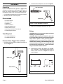
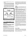
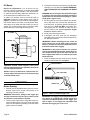
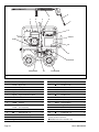
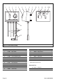
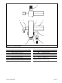
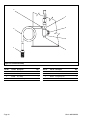
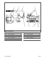
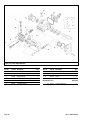
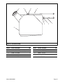
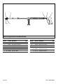
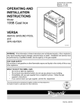
Shark
MODEL 925A/925SS
OPERATING INSTRUCTIONS
AND PARTS MANUAL
R
Read instructions carefully before attempting to assemble, install, operate or service this pressure
washer. Failure to comply with instructions could result in personal injury and/or property damage!
SPECIFICATIONS
● Pump Volume At Pump Head: 3.0 GPM/180 GPH
● Pump Pressure At Pump Head: 3000 PSI
● Burner Type: Fuel Oil Fired, 239,000 BTU/Hr.
● Burner Fuel Pressure: 130 PSI
● Machine Power: 9.0 HP Gasoline Engine, Manual Start
● Machine Weight: 385 Lbs.
● Shipping Weight: 415 Lbs.
● Burner Exhaust Vent: 8"
● Machine Dimensions: Length = 47", Width = 31", Height = 45"
Output specifications are based on engine power curves at 100
meters above sea level and 25o C ambient temperature in accordance with SAE J1349.
SERIAL NUMBER:
SHARK PRESSURE WASHERS
21 INVERNESS WAY EAST
ENGLEWOOD, CO 80112
1-800-771-1881
DATE PURCHASED:
FOR SALES AND SERVICE, PLEASE CONTACT:
WARNING
Read and observe to prevent severe personal injury or property damage.
●
Check hoses, fittings, wand, trigger gun and
fuel connections daily for signs of wear,
cracks and looseness, and replace as
required.
●
Do not store flammable liquids (gasoline,
diesel fuel, solvents, etc.) near pressure
washer or in non-ventilated areas.
●
Use extreme caution when moving pressure washer over rough or uneven surfaces.
●
For permanent installation consult local
building codes for installation requirements. Licensed contractor may be
required.
●
Keep all electrical components on
machine dry.
●
Do not point wand or trigger gun at yourself or at any person. Bodily injury may
result from water under high pressure.
●
Do not block or tie trigger gun in open
position.
●
Wear eye, ear, hand, foot, and skin protection at all times while operating pressure
washer.
Troubleshoot machine prior to using
reset buttons or replacing blown fuses.
See Troubleshooting Guide.
●
Do not place hands or feet on non-insulated areas of the pressure washer when
starting gasoline engine.
Pressure washers produce a kickback. To
prevent personal injuries due to falls use
auxiliary safety equipment.
●
When applying detergents follow the
safety rules on the detergent label.
●
Use detergent from a covered D.O.T.
approved container.
●
Cleaning area should be provided with
adequate slopes and drainage. This will
reduce the possibility of a fall due to slippery surface.
●
Unauthorized machine modification or use
of non-approved replacement parts may
cause personal injury and/or property
damage and will void the manufacturer
warranty.
●
This machine has been provided with
Warning and Instruction decals for the
safety of the operator. If these decals are
removed or become damaged they should
be replaced. Contact your dealer for
replacement decals.
●
●
●
Do not fill engine fuel tank while engine is
running or hot. Let engine cool before
refueling or spontaneous fire may result.
Fuel spillage or vapors could ignite if
engine is hot.
●
Disconnect spark plug and battery prior to
performing any maintenance.
●
Avoid contact with non-insulated areas of
pressure washer to prevent the possibility
of severe burns.
●
Do not allow machine to run unattended.
●
Do not run machine indoors or in an
enclosed area, as exhaust fumes may be
hazardous to your health.
●
Do not operate machine in areas where
flammable vapors, (gasoline, solvents, etc.)
may be present, as this machine may
ignite the vapors.
Page 2
Shark 925A/925SS
DETERGENT
NOZZLE
DUAL LANCE WAND
TRIGGER GUN
PRESSURE HOSE
PRESSURE
NOZZLE
RELIEF VALVE
BURNER EXHAUST VENT
NOZZLE HOLDERS
ENGINE
BATTERY BOX
BURNER SWITCH
THERMOSTAT
DETERGENT
INJECTOR
CONTROL BOX
GARDEN HOSE
CONNECTOR
OIL BURNER
FUEL TANK
PUMP
COIL DRAIN PLUG
OIL BURNER
DETERGENT INLET LINE
Figure 1 - Machine Component Layout
Shark 925A/925SS
Page 3
ASSEMBLY
2. Assemble wand components as shown in Figure 3.
Unpacking
DUAL LANCE WAND
Unpack carefully. Wear safety glasses or goggles while
unpacking, assembling, or operating pressure washer. If
there are missing components or hidden damage,
immediately contact carrier concerning discrepancies.
1. Cut strapping band from pressure washer and pallet.
2. Remove pressure washer from pallet.
Parts Included
•
•
•
•
•
•
•
•
Pressure Washer
Pressure Hose
Trigger Gun
Dual Lance Wand
Pressure Nozzle (3 ea.)
Battery Terminal (2 ea.)
Operating Instructions/Parts Manual
Gasoline Engine Manual
Tools Required
• 1/2" Open End Wrench
• Flat Blade Screwdriver
Pressure Hose, Trigger Gun and Wand
1. Install the pressure hose on the pressure washer as
shown in Figure 2.
TRIGGER GUN
Figure 3 - Trigger Gun/Dual Lance Wand
3. Make sure all plumbing connections are tight.
Battery
WARNING: Wear eye, hand and skin protection when
handling or connecting battery.
WARNING: Batteries generate explosive gases during normal battery operation. Do not expose the battery to flame or sparks as these gases may ignite.
WARNING: Battery fluid is highly acidic. If battery fluid
contacts skin or clothing, wash immediately with soap
and water. If battery fluid enters eye, immediately flood
eye with running cold water for at least 15 minutes
and get immediate medical attention.
1. Place battery in battery box (battery not included).
Use a standard 12 volt automotive battery. Select a
battery similar to the one in Figure 4 for proper fit
and installation.
RELIEF VALVE
-
+
PRESSURE HOSE
10-1/2”
MAX
8-3/4”
MAX
6-3/4”
MAX
Figure 4 - Battery Dimensions
Figure 2 - Pressure Hose Installation
Page 4
Shark 925A/925SS
2. Install the provided battery terminals as shown in
Figure 5.
3. To reduce the possibility of sparking attach the wires
to the battery in the following order. Refer to Figure 5.
First attach the red wire from the voltage regulator
and the red wire from the control box to the positive
“+” terminal of battery. Next, attach the black wire from
the control box and the black wire from the voltage
regulator to the negative “-” terminal of the battery. To
disconnect the battery remove the wires in the opposite order as installed. Install battery box cover and
fasten in place.
BOX STRAP
RED WIRE FROM
CONTROL BOX
RED WIRE
FROM VOLTAGE
REGULATOR
DANGER: Do not run machine indoors or in an
enclosed area, as exhaust fumes may be hazardous
to your health.
DANGER: Do not operate machine in areas where
flammable vapors (gasoline, solvents, etc.) may be
present, as this machine may ignite the vapors.
BLACK WIRE
FROM VOLTAGE
REGULATOR
CAUTION: All venting must be in accordance with
applicable federal and state laws, and local ordinances. Consult local heating contractors.
BLACK WIRE
FROM
CONTROL BOX
BATERY BOX
Figure 5 - Battery Connections
INSTALLATION
Getting Started
IMPORTANT: Proper initial installation of equipment
will assure more satisfactory performance, longer service life, and lower maintenance cost.
IMPORTANT: The use of a backflow preventer on the
water supply hose is recommended and may be
required by local code.
The pressure washer should be run on a level surface
and in a protected area where it is not readily influenced
by outside forces such as strong winds, freezing
temperatures, rain, etc. The pressure washer should be
located to assure easy access for filling of fluids,
adjustments and maintenance. Normal precautions should
be taken by the operator to prevent moisture from reaching
the pressure washer. It is recommended that a partition
Shark 925A/925SS
Venting
BATTERY BOX
BATTERY
TERMAINAL
12 VOLT BATTERY
be made between the wash area and the pressure washer
to prevent direct spray from the wand from coming in
contact with the pressure washer. Moisture reaching the
equipment will reduce the pressure washer’s service life.
All installations must comply with the local codes covering
such installations.
If the pressure washer is to be used in an enclosed area,
a flue must be installed to vent burner and engine exhaust
to the outside atmosphere. Be sure the flue is the same
size as the burner exhaust vent on the pressure washer.
See Figure 1 for location. Poor draft will cause the
pressure washer to soot and not operate properly. When
selecting the location for installation, beware of poorly
ventilated locations or areas where exhaust fans may
cause an insufficient supply of oxygen. Proper combustion
can only be obtained when there is a sufficient supply of
oxygen available for the amount of fuel being burned. If it
is necessary to install the machine in a poorly ventilated
area, outside fresh air may have to be piped to the burner
and a fan installed to bring sufficient air into the machine.
Locate the pressure washer so that the flue will be as
straight as possible and protrude through the roof at a
proper height and location to provide adequate draft. This
oil fired pressure washer must have a draft regulator
installed in the flue (available from most heating
contractors). A draft regulator will permit proper upward
flow of exhaust flue gases.
In addition, the pressure washer should never be operated
in an enclosed area where high ambient temperatures
exist. High ambient temperatures (above 100o F) can
cause engine oil failure and will greatly reduce the engine’s
performance.
Gasoline Engine
This gasoline engine is preset for operation at altitudes
below 3000 feet above sea level. If operated at higher
altitudes, it may be necessary to install a high altitude
main jet in the carburetor. Contact an authorized engine
sales and service center for details.
Page 5
Oil Burner
Burner Air Adjustment: The oil bur ner on this
machine is preset for operation at altitudes below 3000
feet. If operated at higher altitudes, it may be necessary
to adjust the air band setting. Adjust the air band for a #1
or #2 smoke spot on the Bacharach scale.
To adjust, start machine and turn burner ON (refer to
Operation for details). Loosen locking screw (refer to
Figure 6) and close air band until black smoke appears
from burner exhaust vent. Note air band position. Next,
slowly open the air band until white smoke just starts to
appear. Turn air band halfway back to the black smoke
position previously noted. Tighten locking screw.
OIL BURNER
AIR BAND
3. Fill oil burner fuel tank. Use kerosene, #1 grade home
heating oil, #1 or #2 diesel fuel. DO NOT USE GASOLINE, CRANKCASE OIL DRAININGS, OR WASTE
OIL.
WARNING: Do not fill engine fuel tank while engine
is running or hot. Let engine cool before refueling or
spontaneous fire may result. Fuel spillage or vapors
could ignite if engine is hot.
4. Fill the engine fuel tank. Do not overfill, fill to the bottom of filler neck only. Use lead free gasoline minimum 86 octane, or lead free gasoline containing no
more than 15% MTBE. DO NOT use gasoline containing more than 5% methanol or more than 10%
ethanol. Refer to the provided gasoline engine
manual for additional details.
5. Check pump and engine oil levels.
6. If detergents are to be used, only use detergents
intended for pressure washers. Follow instructions on
the detergent container.
IMPORTANT: Before installing pressure nozzle on
initial start-up, turn on the water supply and allow
water to run from the end of the wand until clear to
prevent the nozzle from clogging.
IMPORTANT: If the pressure washer has not been
used for an extended period of time, remove the pressure nozzle from the end of the wand and turn on
water supply. Allow water to run from the end of the
wand until clear.
LOCKING SCREW
7. Install the proper pressure nozzle for your cleaning
needs on end of wand, refer to Figure 7.
Figure 6 - Burner Adjustment
PRESSURE NOZZLE
CAUTION: If white smoke appears from burner
exhaust vent during start-up or operation, discontinue
use and readjust air bands.
NOTE: If a flue is installed, have a professional serviceman adjust your burner for a #1 or #2 smoke spot
on the Bacharach scale.
OPERATION
DUAL LANCE WAND
TRIGGER GUN
Before Starting
1. Read all manuals provided with this pressure washer.
Become familiar with location and function of all
operating and safety controls.
WARNING: Check hoses, fittings, wand, trigger gun
and fuel connections daily for signs of wear, cracks
and looseness, and replace as required.
2. Connect water supply hose to the garden hose connector located on pump. The water faucet and supply
hose must be capable of providing a minimum of 3.0
gallons per minute (GPM).
Page 6
TRIGGER LOCK
Figure 7 - Nozzle Installation/Trigger Lock
IMPORTANT: The trigger gun provided with this pressure washer is equipped with a manual trigger lock
to prevent accidental operation of the trigger gun,
refer to Figure 7. The trigger lock should be used
whenever the trigger gun is not in use.
Shark 925A/925SS
To Start
DANGER: Do not point wand or trigger gun at yourself or at any person. Bodily injury may result from
water under high pressure.
refer to Figure 8. The output pressure is automatically reduced for detergent application. Allow
detergent to reach end of wand before proceeding to
step 2.
DUAL LANCE WAND
WARNING: Wear eye, ear, hand, foot and skin protection at all times while operating pressure washer.
IMPORTANT: The water must be turned on before
starting. Running the pump dry will cause damage
and void warranty.
OPEN
CLOSE
IMPORTANT: Do not allow the machine to run with
trigger of the trigger gun released for more than
10 minutes at any one time or damage to pump may
occur.
1.
2.
3.
4.
Turn ON water supply.
Hold wand firmly, release trigger of trigger gun.
Turn engine ON/OFF switch to ON position.
Turn fuel shut-off valve to ON position (if so equipped).
Move choke lever to FULL CHOKE position, (choke
may not be needed on warm engine). Move throttle
lever to HALF THROTTLE position.
5. Pull the rope starter slowly until resistance is felt, then
pull briskly. Do not allow the rope starter to snap back
against the engine. Return it gently to prevent damage to the starter.
6. When the engine starts, move choke lever until
engine runs smoothly. Move throttle lever to FULL
THROTTLE position. When engine war ms, move
choke lever to NO CHOKE position.
IMPORTANT: To allow for proper battery charging the
throttle control must be kept in the full throttle position during operation.
NOTE: If engine fails to start, refer to Troubleshooting Guide in this manual.
7. Squeeze trigger of trigger gun and allow air to purge
from system.
8. If HOT water is desired, adjust the thermostat to the
proper temperature and turn burner switch ON. The
burner will light immediately with a small puff of smoke.
You may need to initially adjust your burner for peak
performance. See Oil Burner section under Installation. If smoke continues, contact Customer Service
at 1-800-771-1881. When the trigger of the trigger
gun is released or when the thermostat temperature
setting is reached, the burner will automatically turn
off.
To Clean
DANGER: Do not place hands or fingers in front of
high pressure spray. Bodily injury may result.
1. Insert detergent inlet line into container of mixed
detergent. Squeeze the trigger of the trigger gun.
Open detergent control handle on the dual lance wand,
Shark 925A/925SS
DETERGENT CONTROL HANDLE
Figure 8 - Dual Lance Wand Operation
2. Wash from the bottom to the top, using side to side
motions. This washes away heavy dirt and allows the
detergent to soak as you work toward the top.
3. Do not wash at a 90o angle to work (straight at it).
This will allow water to splash back at you and
reduces your cleaning power. Wash at a 30o to 60o
angle to the work. This will allow the water to splash
away from you and the water will wash the dirt away
faster and easier.
4. Use the full width of the spray pattern to wash in
a wide path. Overlap spray paths for complete
coverage. Wash from side to side, using slow, steady
motions.
5. The nozzle should be 12" to 24" from work, closer for
tough areas. Be careful on painted or delicate surfaces, the pressure may damage surface if nozzle is
too close.
6. Small parts should be washed in a basket so the pressure does not push them away. Larger, lightweight
parts should be clamped down so the pressure does
not push them away.
7. Close the detergent control handle on the dual lance
wand to permit high pressure rinse, refer to Figure 8.
Rinse from top to bottom to prevent detergent from
dripping onto rinsed area.
To Stop
1. If detergents were used, draw clear water through the
detergent inlet line to purge detergent. Failure to do
so may clog detergent injector valve.
2. If burner was used, turn OFF burner switch and
allow pump to run cold water through coil for several
minutes.
3. Move throttle lever to idle position.
4 Turn engine ON/OFF switch to the OFF position.
5. Close fuel shut-off valve.
6. Turn water supply OFF.
7. Squeeze trigger of trigger gun to relieve system
pressure.
Page 7
STORAGE
DANGER: Do not store flammable liquids (gasoline,
diesel fuel, solvents, etc.) near pressure washer, or
in non-ventilated areas.
Protect from freezing by storing in a heated area, or by
flushing the system with antifreeze (use an automotive
engine antifreeze or windshield washer solvent to
antifreeze). To flush the system with antifreeze, the
following steps are to be followed:
1. Open detergent control handle on dual lance wand,
refer to Figure 8.
2. Connect the water supply hose to the garden hose
connector located on the pump. Turn on water supply.
3. Place the detergent inlet line into a container of antifreeze.
4. Hold wand firmly, release trigger of trigger gun.
5. Start engine. Place throttle lever in FULL THROTTLE
position.
6. Squeeze trigger of trigger gun and allow water to flow
from the end of the wand. Watch for antifreeze to be
drawn through the detergent inlet line. Allow the antifreeze to be drawn into the system for 5 to 10 seconds.
7. Release the tr igger of the trigger gun and stop
engine.
8. Turn off water supply and disconnect water supply
hose from the pump.
9. Attach a short length of hose (approximately 3 feet
long) to the garden hose connector located on the
pump. Install a funnel in the other end of the hose as
shown in Figure 9.
FUNNEL
10. Hold wand firmly, release the trigger of the trigger
gun.
11. Start engine. Place throttle lever in the idle position.
12. Squeeze trigger on trigger gun.
13. Slowly pour antifreeze into the funnel. Continue to add
antifreeze until antifreeze flows from the end of the
wand.
14. Squeeze and release the trigger of the trigger gun
several times to antifreeze the unloader system.
15. Release the trigger of the trigger gun. Stop engine.
16. Squeeze the trigger of the trigger gun to relieve system pressure.
For added protection, after antifreezing, disconnect the
pressure hose from the machine and remove the coil drain
plug (refer to Figure 1 for location.) After coil has drained,
replace pressure hose and coil drain plug. If the pressure
washer is not to be used for an extended length of time, it
is recommended that the system be flushed with
antifreeze for rust protection. Refer to the Gasoline
Engine Manual for engine storage information.
MAINTENANCE
WARNING: Unauthorized machine modification or
use of non-approved replacement parts may cause
personal injury and/or property damage and will void
the manufacturer warranty.
Pump
Lubrication: To lubricate pump, use 10W30 nondetergent oil for pump crankcase. Crankcase must be filled
to red dot on oil gauge found on the rear of the pump,
refer to Figure 10. During the break-in-period, make sure
the oil is changed after the first 50 hours of operation.
After that, replace oil every 3 months or 500 hours of
operation, whichever comes first.
OIL GAUGE
OIL FILL / DIPSTICK
GARDEN HOSE
CONNECTOR
OIL DRAIN
Figure 9 - Winterizing
Figure 10 - Pump Lubrication
Page 8
Shark 925A/925SS
Proper Pump Care:
• Do not pump acids.
• Do not allow pump to run dry.
• Winterize if storing in freezing temperatures, refer
to Storage for details.
• Use a water softener on the water system if known
to be high in mineral content.
• Use only high quality detergents and follow manufacturer’s mix recommendations.
• Flush the system with clear water immediately
after using detergent solutions.
• Clean filter screen on detergent inlet line periodically.
• Flush the pressure washer system with antifreeze
if storing for an extended period of time, refer to
Storage for details.
Gasoline Engine
Refer to the provided gasoline engine manual for
recommended maintenance.
Oil Burner
Blower Motor: Inspect the motor brushes for wear
every 250 hours of operation and replace when 1/8" to
1/4" brush material remains. DO NOT allow the brushes
to wear out completely or motor damage will occur. Refer
to Figure 22. The motor bearings are permanently
lubricated and will not require any additional lubrication.
Relief Valve
WARNING: The relief valve on this pressure washer
has been factory set and sealed and is a field nonadjustable part. Tampering with the factory setting
may cause personal injury and/or property damage,
and will void the manufacturer warranty. For replacement parts refer to Figure 15.
Shark 925A/925SS
Unloader Valve
WARNING: The unloader valve on this pressure
washer has been factory set and sealed and is a field
non-adjustable part. Tampering with the factory
setting may cause personal injury and/or property
damage, and will void the manufacturer warranty. For
replacement refer to Figure 18.
Burner Fuel Filter
Drain any water which has accumulated in fuel filter and
clean or replace filter element as needed. Refer to
Figure 21.
Heating Coil
Coil Descaling: In hard water areas, scale buildup within
the heating coil will occur. Scale deposits will decrease
the water temperature rise and may eventually clog the
heating coil. Contact your local service center when
descaling is needed.
Coil Desooting: Poor grades of fuel oil or inadequate
combustion air will cause heavy soot buildup on the
outside surface of the heating coil. These deposits will
insulate the coil. This will restrict the air flow through the
coil, further aggravating the soot buildup. Contact your
local service center when desooting is needed.
Hour Meter
An optional hour meter (P/N 783865) is available for use
on the Model 925A/925SS. This hour meter will monitor
the total hours of operation of the pressure washer to
signal when routine maintenance is required.
Battery
Refer to battery manufacturer’s literature for recommended maintenance.
Page 9
TROUBLESHOOTING GUIDE
SYMPTOM
POSSIBLE CAUSES
CORRECTIVE ACTION
Gas engine will not run.
Out of gas.
Replenish supply. Use only recommended fuels. Refer to Before
Starting under Operation.
Fuel valve closed (if so equipped).
Open valve.
Loose spark plug wire.
Reconnect.
Choke or throttle set incorrectly.
Refer to To Start under Operation.
Engine ON/OFF switch in OFF
position.
Place engine ON/OFF switch in ON
position.
Low engine oil level.
Replenish supply. Engine will not start
or run if oil is low (on engines equipped with low oil protection).
Refer to provided gasoline engine manual for additional troubleshooting.
Pressure washer runs
but won't spray.
Trigger of trigger gun released.
Squeeze trigger.
Water supply not turned on.
Open water supply valve.
Clogged pressure nozzle.
Clean pressure nozzle opening.
Inadequate water supply.
Fully open faucet. Check for kinked or
damaged hose. Use 5/8 inch minimum hose. Check for debris clogging
inlet screen.
Partially clogged or damaged
pressure nozzle.
Clean or replace.
Air being drawn through detergent
inlet line.
Refill detergent container. Ensure
that pick-up screen is fully immersed.
Dual lance wand set for detergent
application.
Set dual lance wand for rinse. Refer
to Step 7 under To Clean. Washer
will not create high pressure when
set for detergent application.
Uneven spray pattern.
Partially clogged or damaged
pressure nozzle.
Clean or replace.
Pressure washer will
not produce hot water.
Burner switch in OFF position.
Place switch in ON position.
Inadequate fuel supply.
Refill fuel tank. Use only recommended fuels. Refer to Before
Starting under Operation.
Engine not running.
Engine must be running before
burner will light.
Inadequate water supply.
Fully open faucet. Check for kinked
or damaged hose. Use 5/8 inch minimum hose. Check for debris clogging
inlet screen.
Low spray pressure
at nozzle.
Page 10
Shark 925A/925SS
TROUBLESHOOTING GUIDE
SYMPTOM
POSSIBLE CAUSES
CORRECTIVE ACTION
Pressure washer will
not produce hot water.
...continued
Trigger of trigger gun released.
Squeeze trigger. Water must be
spraying for burner to light.
Thermostat is set too low.
Adjust thermostat to desired temperature.
Blown fuse.
Replace. Fuse is located in Control
Box. Refer to Figure 14 for location.
Engine is running too slow.
Move throttle lever to full throttle position.
Battery charge is low.
Charge battery or replace if necessary.
Inadequate detergent supply.
Refill detergent container. Ensure
that pick-up screen is fully immersed.
Detergent screen or hose clogged.
Clean. Always start with a clean
detergent container.
Dual lance wand set for high
pressure.
Set dual lance wand for detergent
application. Refer to Step 1 under To
Clean.
Clogged detergent injector check
valve.
Clean check valve at detergent
injector inlet.
Improper detergent concentration or
mixing.
Mix detergent per manufacturer's
instructions. Ensure that powdered
detergents are fully dissolved.
Wrong detergent for the application.
Select appropriate detergent.
Rinsing with hot water.
A final rinse with cold water will
reduce water spotting.
Poor or no detergent
flow.
Poor cleaning.
IMPORTANT
If the pressure washer demonstrates other symptoms or the corrective
actions listed do not correct the problem, contact the local authorized Shark
Pressure Washer Service Center. The Shark Pressure Washer Service
Center can be identified by contacting:
Customer Service Department
Shark Pressure Washers
21 Inverness Way East • Englewood, Colorado 80112
1-800-771-1881
Shark 925A/925SS
Page 11
When ordering from your dealer, please provide the following:
Model Number: 925A/925SS
Machine Serial Number: ________________________________
Component Part Number: _______________________________
Description: __________________________________________
FOR HELP OR ADDITIONAL INFORMATION, CONTACT:
Customer Service Department
Shark Pressure Washers
21 Inverness Way East
Englewood, CO 80112
1-800-771-1881
Page 12
Shark 925A/925SS
7,8,9
10
11
12,13
14
5,6
4
15,16
3
17,18,19,20
2
1
20,21,22,23,24
Figure 11 - Machine Assembly, Left Side View
Ref. No.
Part No. Description
Qty.
Ref. No.
Fig. 14
Part No. Description
Control Box Assembly
Qty.
1
1
375448
Chassis
1
14
2
646089
Decal Warnings
1
15
826167
Strain Relief
2
3
444469
Decal Shark Detergent
1
16
703127
Strain Relief Nut
2
4
Fig. 16
Coil Inlet Assembly
1
17
Fig. 19
Fuel Tank Assembly
1
834153
Decal Fuel Type
1
5
829980
Shark Logo Plate
2
18
6
926598
Rivet
8
19
■
Bolt 1/4” - 20 x 1/2”
2
7
213044
Burner Exhaust Vent
1
20
■
Flat Washer 1/4”
6
8
268004
Insulation
1
21
220119
Battery Box
1
890904
Battery Terminal
2
9
860102
Retaining Ring
1
22
10
824115
Vent Clip
4
23
375292
Mounting Plate
1
11
Fig. 17
Pump Assembly
1
24
■
Locknut 1/4” - 20
4
12
■
Bolt 3/8” - 16 x 1-3/8”
4
13
■
Lock Washer 3/8”
4
Shark 925A/925SS
■ Standard hardware item available locally.
Page 13
6
5
1
2
3
4
7
8
9,10,11
15,26
12
13
14,15,16
22,23,24,25
21
17,18,19,20
Figure 12 - Machine Assembly, Right Side View
Ref. No.
Qty.
Ref. No.
1
661254
Part No. Description
Engine 9 HP
1
15
■
Part No. Description
Flat Washer 5/16”
Qty.
7
2
961532
Tubing 3/8”
]
16
799362
Crownlock Nut 5/16” - 18
3
3
823987
Hose Clamp
1
17
817322
Hubcap
4
4
Fig. 15
Coil Outlet Assembly
1
18
848616
Push Nut
4
5
Fig. 20
Trigger Gun/Dual Lance Wand
1
19
■
Flat Washer 5/8”
8
6
707226
Pressure Hose
1
20
983013
Wheel
4
7
826176
Quick Disconnect
1
21
815329
Snap Bushing
1
8
268006
Insulation
1
22
860232
Voltage Regulator
1
9
375444
Coil Tank (925A)
1
23
218189
Regulator Harness
1
375449
Coil Tank (925SS)
1
24
■
Locknut 1/4” - 20
2
10
■
Fender Washer 5/16”
4
25
■
Flat Washer 1/4”
2
11
■
Flange Nut 5/16” - 18
4
26
■
Locknut 5/16” - 18
4
12
646047
Decal Troubleshooting
1
13
213191
Insulation
1
✽ Order amount needed in feet.
14
Fig. 21
Burner Assembly
1
■ Standard hardware item available locally.
Page 14
Shark 925A/925SS
1
2
3
2
4
5
6
10
9
8
7
2
Figure 13 - Machine Assembly, Top View
Ref. No.
1
Part No. Description
Qty.
Ref. No.
Part No. Description
1
7
890783
Tag Gasoline Engine
Qty.
646088
Decal Operating Instruction
2
815329
Snap Bushing
3
8
444462
Decal Caution Gasoline
1
3
834154
Decal Winterize
1
9
232025
Decal Important Battery
1
4
226222
Coil
1
10
646026
Decal Carbon Monoxide
1
5
859815
Grommet (Nozzle Holder)
3
11
646115
Decal Hot Surface
1
6
859806
Grommet
1
Shark 925A/925SS
1
Page 15
1
2
3
4
5
6
7
8
9
10
11
12
13
14,15
16
17
18
Figure 14 - Control Box Assembly
Ref. No.
Qty.
Ref. No.
1
875465
Part No. Description
Burner Switch
1
13
645990
Part No. Description
Bridge Rectifier
Qty.
1
2
645932
Decal Control Box
1
14
676638
Fuse 30A
1
3
835150
Thermostat Dial
1
15
707146
Fuse Holder
1
4
915390
Thermostat Mounting Plate
1
16
826184
Strain Relief
4
5
■
Screw (4 mm x 6 mm)
2
17
847750
Wire Cover
]
6
615413
Control Box Front
1
18
✪ 875651
Pressure Switch
1
7
630649
Channel
2
■ Standard hardware item available locally.
✽ Order amount needed in feet
8
615414
Control Box Back
1
9
■
Locknut 1/4” - 20
4
10
■
Bolt 1/4” - 20 x 3/4”
4
Replacement Parts
11
955940
Thermostat
1
✪ 753134
O-Ring Kit
1
12
860140
Isolation Relay
1
✪ 875653
Switch
1
Page 16
Shark 925A/925SS
10
1
2
3
4
5
8,9
6
7
Figure 15 - Coil Outlet Assembly
Ref. No.
Qty.
Ref. No.
1
799501
Part No. Description
Elbow 1/4” x 3/8” Hose
1
7
■
Screw (4 mm x 6 mm)
1
2
875555
Relief Valve Seat
1
8
780565
Copper Washer
2
3
783845
Relief Valve Manifold
1
9
915630
Plug 3/8”
2
4
630720
Relief Valve Cartridge
1
10
698247
Hex Nipple 1/2” x 2”
1
5
644802
Street Elbow 3/8”
1
6
844806
Quick Disconnect Plug
1
Shark 925A/925SS
Part No. Description
Qty.
■ Standard hardware item available locally.
Page 17
3
7
6
2
5
1
4
Figure 16 - Coil Inlet Assembly
Ref. No.
Qty.
Ref. No.
1
935159
Filter Screen
1
5
754711
Tee 3/8”
1
2
961534
Tubing 1/4”
✽
6
801102
Hex Nipple 3/8” x 1-1/2”
1
3
823989
Hose Clamp
1
7
873594
Detergent Injector
1
4
715744
Coil Drain Plug
1
Page 18
Part No. Description
Part No. Description
Qty.
✽ Order amount needed in feet.
Shark 925A/925SS
1
2
4
3
9
4
8
5,6,7
Figure 17 - Pump Assembly
Ref. No.
Qty.
Ref. No.
1
829938
Part No. Description
Pump Fig. 18
1
6
801139
Garden Hose Connector
1
2
890769
Tag Unloader
1
7
856035
Garden Hose Connector Gasket
1
3
707179
Hose 3/8” x 30”
1
8
844758
Street Elbow 1/2”
1
4
644802
Street Elbow 3/8”
2
9
915567
Plug Pipe 1/2”
1
5
875575
Garden Hose Connector Spring
1
Shark 925A/925SS
Part No. Description
Qty.
Page 19
8
9
1
2
3
7
4
2
1
6
5
Figure 18 - Pump, Exploded View
Ref. No.
Qty.
Ref. No.
1
835225
Part No. Description
Valve Plug
6
7
755256
Pump Mounting Kit
1
2
753164
Check Valve Kit
6
8
646327
Oil Fill/Dipstick
1
3
753165
Plunger Seal Kit
3
9
814285
Gasket
1
4
✪ 755250
Unloader Assembly
1
5
885426
Crankcase Oil Seal
3
Replacement Parts
6
885425
Crankshaft Oil Seal
1
✪ 755255
Page 20
Part No. Description
Qty.
Qty/Pump
Unloader O-Ring Kit
1
Shark 925A/925SS
1
2
3
4
5
6
7
8
Figure 19 - Fuel Tank Assembly
Ref. No.
Qty.
Ref. No.
1
817312
Part No. Description
Fuel Tank Cap
1
6
309294
Nipple 3/8” Hose x 1/4” Hose
1
2
661277
Elbow 1/4” Hose x Stand Pipe
1
7
867368
Hose 1/4” Black
✽
3
823988
Hose Clamp
4
8
890890
Fuel Tank
1
4
707116
Hose 1/4” Green
✽
5
815230
Bushing
2
Shark 925A/925SS
Part No. Description
Qty.
✽ Order amount needed in feet.
Page 21
5
6
1,2,3
7
8
9
4
Figure 20 - Trigger Gun/Dual Lance Wand Assembly
Ref. No.
Qty.
Ref. No.
1
799177
Part No. Description
Pressure Nozzle (Red)
1
7
826169
Quick Disconnect
1
2
799178
Pressure Nozzle (Yellow)
1
8
915786
Quick Disconnect Plug
1
3
799179
Pressure Nozzle (White)
1
9
✹ 691867
Trigger Gun
1
4
826170
Quick Disconnect
1
Replacement Parts
5
900958
Detergent Nozzle
1
✪ 859762
Insulator Grip Assembly
1
6
✪ 936686
Dual Lance Wand
1
✹ 753179
Trigger Gun Repair Kit
1
Page 22
Part No. Description
Qty.
Shark 925A/925SS
1
1/8”
1/8”
2
NOZZLE
3
4
5
6
AIR CONE
5/16”
3/16”
NOZZLE
ELECTRODE
ELECTRODE SETTINGS
7
8,9
10,11
Figure 21 - Burner Assembly
Ref. No.
Part No. Description
Qty.
Ref. No.
Part No. Description
Qty.
1
615850
Burner Fig. 22
1
8
826167
Strain Relief
1
2
698023
Nipple 3/8” x 1/4” Hose
1
9
703127
Strain Relief Nut
1
851080
Fuel Filter
1
10
■
Screw #6 - 32 x 1”
1
■
Locknut #6 - 32
1
3
✪
4
615279
Reducer Bushing 3/8” x 1/4”
1
11
5
698200
Pipe Nipple 1/4” x 2-1/2”
1
■ Standard hardware item available locally.
6
661257
Street Elbow 1/4”
1
Replacement Parts
7
698020
Nipple 1/4” x 1/4” Hose
1
✪ 875490
Shark 925A/925SS
Filter Element
1
Page 23
1
2
3
4
5
6
7
8
11
10
9
7
Figure 22 - Burner Parts Breakdown
Ref. No.
Part No. Description
Qty.
Ref. No.
Part No. Description
Qty.
1
9
825924
Coupling
1
1
919791
Fuel Pump
2
944422
Solenoid Valve
1
10
676865
Blower Fan
1
3
890906
Ignitor
1
11
880806
Fuel Line
1
4
901230
Solenoid Metering Bolt
1
NS
875312
Relay
1
5
900650
Nozzle
1
NS
895312
Timer
1
6
661302
Electrode (Pair)
1
NS
890916
Terminal Block
1
7
753167
Brush Kit
2
NS
877667
Tune Up Repair Kit
1
8
784353
Motor
1
NS = Not Shown
Page 24
Shark 925A/925SS
Figure 23 - Wiring Diagram
Shark 925A/925SS
Page 25
Shark
WARRANTY
R
SHARK ONE-YEAR LIMITED WARRANTY:
Shark products are warranted by Shark Pressure Washers (Shark), to be free of defects in material and
workmanship under normal use, for a period of ONE YEAR from the date of the original purchase. Items
that fail due to normal wear such as pump seals, pump valves, unloader valves, detergent valves, water
nozzles, quick couplings, hoses, gunjets, o-rings, etc. are not covered under this warranty. Damage resulting from neglect, abuse, tampering, modification or misuse is not covered under this warranty. Shark will at
its option repair or replace any part covered by this warranty which is defective under normal use for one
year at no charge for parts or labor. All defects must be verified by an authorized Shark Pressure Washers
service location.
EXCEPTIONS TO THE ONE YEAR WARRANTY FOR PARTS ONLY ARE:
Hawk Pumps: SEVEN YEAR Warranty (LIFETIME Brass Manifold Warranty-Even
Against Freezing)
Heating Coils: FOUR YEAR Warranty
Chassis Assembly and Pulleys: THREE YEAR Warranty
Plumbing and Belts: TWO YEAR Warranty (This additional warranty will be in effect as
applicable.)
LIMITATION OF LIABILITY:
To the extent allowable under applicable law, Shark liability for consequential and incidental damages is
expressly disclaimed. Shark liability in all events is limited to, and shall not exceed, the purchase price paid
for the equipment. Shark liability excludes field labor charges, loss of use of the unit, loss of time or rental,
inconvenience, or commercial loss and is limited to repair or replacement of defective parts only, at the
option of Shark Pressure Washers.
WARRANTY DISCLAIMER:
Shark has made a diligent effort to illustrate and describe the product in this literature accurately; however,
such illustrations and descriptions are for the sole purpose of identification, and do not express or imply a
warranty that the product is merchantable, or fits a particular purpose, or that the product will necessarily
conform to the illustrations or descriptions.
PRODUCT SUITABILITY:
Many states and localities have codes and regulations governing sales, construction, installation, and/or
use of products for certain purposes, which may vary from those in neighboring areas. While attempts to
assure that its products comply with such codes, it cannot guarantee compliance, and cannot be responsible for how the product is installed or used. Before purchase and use of a product, please review the
product application, and national and local codes and regulations, and be sure that the product, installation,
and use will comply with them.
PROMPT DISPOSITION:
Shark will make a good faith effort for prompt correction or other adjustments with respect to any product
which proves to be defective within limited warranty. For any product believed to be defective within limited
warranty, contact Shark Pressure Washers at 1-800-771-1881.
SHARK PRESSURE WASHERS
21 Inverness Way East
Englewood, Colorado 80112
1-800-771-1881
785925-10-99