1
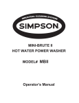
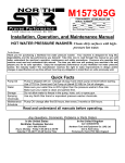
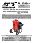
MHOTPWR
ITEM NUMBER: 157321,322,325,326
SERIAL NUMBER:
Proven Performance
K-BAR Industries, Faribault, MN, 55021
HP:______ Volts:______ Amp:______ Ph:_____
RPM:____ PSI:____ GPM:____ Nozzle Size:_____
Pump:___________ Hose:______ Lance:_______
Max. Discharge Temperature:_____________
Installation, Operation, and Maintenance Manual
HOT WATER PRESSURE WASHER: Cleans dirty surfaces with high
pressure hot water.
To the Owner:
Thank you for purchasing a Northstar hot water pressure washer. Your machine is designed for long life,
dependability, and the top performance you demand! Take time now to read through this manual so you better
understand the machine’s operation, maintenance and safety precautions. Everyone who operates this machine
must read and understand this manual. The time you take now will prolong your machine’s life and prepare you
for its safe operation. Enjoy the exceptional performance of your Northstar hot water pressure washer, the
industry leader! The manufacturer reserves the right to make improvements in design and/or changes in
specifications at any time without incurring any obligation to install them on units previously sold.
Quick Facts
Pump Oil
Water
Storage
Spraying
Chemicals
Maintenance
Schedule
Pump is shipped with oil. Change oil plug and check pump oil level before starting.
Use SAE 30 Non-detergent pump oil (item# 4043) or Cat Pump oil (item# 22158) for oil
changes.
Make sure your water flow is 20% higher than the pressure washer’s flow rate.
Make sure your water is clean and particle free.
Do not allow water to freeze in the pump, hose, coil, or spray gun.
Use any North Star brand or equivalent pressure washer chemicals.
Adjust soap adjustment knob to regulate cleaning power.
Pump:
Oil: change after first 50 hours, then every 3 months or 500 hours.
Read and understand all manuals before operating.
Any Questions, Comments, Problems or Parts Orders
In the United States
Northstar Customer Service
Call 1-800-270-0810
Hours: Monday - Friday 7:00 AM to 5:30 PM
Saturday 7:30 AM-11:30 AM Central Time
In the United Kingdom
Call 02392639752
Northern Tool and Equipment Co. (UK) Ltd.
Unit 2, Keel Close,
Portsmouth, Hants PO3 5QD, England
Table of Contents
Important Safety Instructions
Grounding Instructions
Extension Cords
Specifications
Machine Component
Identification
Installation Instructions
Operation Instructions
2
3
3
4
5
6-9
10-12
Safety Features
Maintenance Instructions
Moving and Handling Instructions
Long Term Storage
Troubleshooting
12
13-16
17
17
18-19
Parts Breakdowns
Wiring Diagram
20-26
27-28
Important Safety Instructions
WARNING -Risk of Injection or Injury to Persons - Do Not Direct Discharge Stream at Persons. - Do not use a
hose if exterior damage is evident.
-Risk of explosion. - Do not spray flammable liquids. - Do not operate in a flammable environment.
CAUTION -Risk of Asphyxiation - Exhaust fumes are deadly, for outdoor use only. Avoid inhaling exhaust
fumes.
-Risk of fire. Do not add fuel when the product is operating or hot.
-Gun kicks back. Hold with both hands.
-To reduce the risk of injury, read operating instructions carefully before use.
WARNING - When using this product basic precautions should always be followed, including the following:
1.) Read all the instructions before using the product.
2.) To reduce the risk of injury, close supervision is necessary when the product is used near children. Do
not allow irresponsible use by children. Always stop the product and bleed pressures before leaving
unattended, disconnecting hoses, or servicing the pump.
3.) Know how to stop the product and bleed pressures quickly. Be thoroughly familiar with the controls.
4.) Stay alert - watch what you are doing.
5.) Do not operate the product when fatigued or under the influence of alcohol or drugs. Never smoke while
operating or fueling this machine.
6.) Keep operating area clear of all persons.
7.) Do not overreach or stand on unstable support. Keep good footing and balance at all times. Wear
footwear capable of maintaining a good grip on wet surfaces - Do not place the machine on soft or
unstable ground.
8.) Follow the maintenance instructions specified in all manuals. Do not run machine without sufficient
lubrication or sufficient water to cool the pump.
9.) Wear safety glasses, gloves, face protection and appropriate clothing when operating the machine.
10.)Do not operate this machine with broken or missing parts. - Never alter the manufacturer’s original
design or deactivate any safety device on the machine.
11.)Risk of exposure to dangerous chemicals. Wear protective gloves when handling and cleaning with
chemicals. Follow the chemical manufacturer’s directions. Understand all safety hazards and first aid for
all chemicals being used. Check whether dangerous chemicals have been used and take any
precautions that may have been recommended by the supplier of these chemicals when cleaning filters.
Do not pump highly abrasive fluids or use with incompatible chemicals or solvents.
12.)Know the pressure and temperature limits of your machine. Be sure all high pressure accessories meet
or exceed your machine’s limits. Do not set the pressure relief valve above the machine’s limit.
13.)Do not move this machine by pulling on the hose. Do not use the pump to support other items of
equipment that impose unacceptable loads on the pump. Do not attempt to use this machine as a prop.
14.)To reduce risk of injury, do not secure the spray gun open. Your spray gun is equipped with a built-in
trigger safety latch to guard against accidental trigger release and potentially dangerous high pressure
spray. Rotate the safety latch to the locked position when not spraying.
15.) Do not clean this machine with its own spray. Cleaning should be done with a damp sponge with the
motor OFF.
16.) NEVER attempt to immediately run or re-light the burner if it doesn’t ignite the first time. Unburned oil or
gas may have accumulated causing potential explosion or fire hazard.
17.) Always make sure all switches and controls are in the OFF position prior to plugging in the electrical
cord. Do no stand in water while plugging and unplugging electrical cord.
18.) This product is provided with a ground fault circuit interrupter built into the power cord plug. If
replacement of the plug or cord is needed, use only identical replacement parts.
SAVE THESE INSTRUCTIONS
2
Grounding Instructions
This product must be grounded. If it should malfunction or breakdown, grounding provides a path of least resistance for
electric current to reduce the risk of electrical shock. This product is equipped with a cord having an equipment-grounding
conductor and a grounding plug. The plug must be plugged into an appropriate outlet that is properly installed and
grounded in accordance with all local codes and ordinances.
DANGER - Improper connection of the equipment - grounding conductor can result in a risk of electrocution. Check with a
qualified electrician or service personnel if you are in doubt as to whether the outlet is properly grounded. Do not modify
the plug provided with the product - if it will not fit the outlet, have a proper outlet installed by a qualified electrician. Do not
use any type adapter with this product.
1. For a product rated 125 volts or less:
GROUND FAULT CIRCUIT INTERRUPTER PROTECTION
This pressure washer is provided with a ground fault circuit interrupter (GFCI) built into the plug of the power supply cord.
This device provides additional protection from the risk of electric shock. Should replacement of the plug or cord become
necessary, use only identical replacement parts that include GFCI protection.
2. For a product rated more than 125 volts:
GROUND FAULT CIRCUIT INTERRUPTER PROTECTION
To comply with the National Electric Code (NFPA 70) and to provide additional protection from the risk of electric shock,
this pressure washer should only be connected to a receptacle that is protected by a ground fault circuit interrupter
(GFCI).
Extension Cords
Use only 3-wire extension cords that have 3 prong grounding-type plugs and 3-pole cord connectors that accept the plug
from the product. Use only extension cords that are intended for outdoor use. These extension cords are identified by a
marking “Acceptable for use with outdoor appliances; store indoors while not in use.” Use only extension cords having an
electrical rating not less than the rating of the product. Do not abuse extension cord and do not yank on any cord to
disconnect. Keep cord away from heat and sharp edges. Always disconnect the extension cord from the receptacle before
disconnecting the product from the extension cord.
Warning - To reduce the risk of electrocution, keep all connections dry and off the ground. do not touch plug with wet
hands.
SAVE THESE INSTRUCTIONS
3
Specifications
Item Number
Pressure Rating
Flow Output
Pump Type
Water Supply
Motor Horsepower
BTU Output
Temperature Rise
Maximum
Temperature
Approved Fuels
Fuel Capacity
Discharge Hose
Power
Requirements
NEMA
Receptacles
Volts
Amps
Hertz
Phase
Dimensions
Length
Width
Height
Ship Weight
157321
157322
157325
157326
1000 psi
2 gpm
Ceramic Triplex
Plunger
Standard tap water
@ 20-100psi
1.5 hp
221,400 BTU
140 F
2000 psi
3.5 gpm
Ceramic Triplex
Plunger
Standard tap water
@ 20-100psi
5 hp
270,000 BTU
140°F
210°F
1000 psi
2 gpm
Ceramic Triplex
Plunger
Standard tap water
@ 20-100psi
1.5 hp
221,400 BTU
140°F - (190°F steam
mode)
250°F
210°F
2000 psi
3.5 gpm
Ceramic Triplex
Plunger
Standard tap water @
20-100psi
5 hp
270,000 BTU
140°F - (190°F steam
mode)
250°F
#1 or 2 Diesel,
Kerosene, Fuel Oil
8.25 gal.
3/8” x 30’
#1 or 2 Diesel,
Kerosene, Fuel Oil
8.25 gal.
3/8” x 50’
#1 or 2 Diesel,
Kerosene, Fuel Oil
8.25 gal.
3/8” x 30’
#1 or 2 Diesel,
Kerosene, Fuel Oil
8.25 gal.
3/8” x 50’
5-20R
5-20R
6-30R
6-30R
115V
20A
60Hz
single
115V
20A
60Hz
single
230V
30A
60Hz
single
230V
30A
60Hz
single
38”
26”
43”
355 lb.
38”
26”
43”
360 lb.
38”
26”
43”
420 lb.
38”
26”
43”
415 lb.
4
Machine Component Identification
157321, 157322, 157325, 157326
1
2
3
4
5
6
7
8
9
Description
Exhaust Vent
High Pressure Water Outlet
Nozzle Holders
Pump
Burner
Fuel Fill Cap
Fuel Tank
Unloader
Motor
Ref #
10
11
12
13
14
15
16
17
18
Description
Control Box
Fuel Filter
Main Power Switch
Service Panel
Thermostat (optional)
Heat Switch
Safety Relief Valve
Power Cord Hanger
Wand Holder
Ref #
19
20
21
22
23
Description
Heating Coil
Garden Hose Water Inlet
Spray Gun
Grip
Dual Lance Wand
5
Installation Instructions
I.) Unpack
Separate and identify all components. Use the assembly instructions in this manual for assembly.
Hex Wrench
Qty-1
Spray Gun & Grip
Qty-1
High Pressure Hose
Qty-1
Fastener Bag
Qty-1
Wheel Retainer
Qty-2
Wheel
Qty-2
Pressure Washer
Qty-1
00786
Nozzle
157321, 157325 Qty-4
157322, 157326 Qty-5
6
II.) Assembly Instructions
A. 1. Carefully raise the pressure washer off the floor by
using blocks or ramps. Make sure the pressure
washer is secure before proceeding.
2. Install the two wheels as shown with grease zerk
away from frame.
3. Slide the two wheel retainers onto the end of the
axle. Tighten the set screw with the hex wrench
provided in the parts bag .
Description
Qty.
Wheel
Wheel Retainer
2
2
Axle
Wheel Retainer
Wheel
B. 1. Install the pressure hose onto the pressure washer
as shown.
2. Connect the other end of the pressure hose to the
spray gun as shown.
3. Make sure all plumbing connections are tight.
Description
Spray Gun/ Lance
Spray Hose
Qty.
1
1
00787
7
III.) Pump Preparation
*AR Pumps Only
A.) Remove the shipping plug from the oil fill hole.
B.) Screw the vented dipstick into oil fill hole.
C.) Check oil level in the pump. Make sure it is 1/2 way
up the sight glass .
AR PUMPS
Oil Fill Hole
Quantities Of Fluid
Pump
AR XTV
AR XMV
Cat 2SFX
Type of Fluid
SAE 30*
SAE 30*
SAE 30**
QTY
8.0oz (0.24L)
14.0oz (0.41L)
11.83oz (0.35L)
*SAE Non-Detergent Oil (order Pump Oil Item# 4043)
**SAE Non-Detergent (order Cat Pump Oil Item# 22158)
IV.) Chemical Injector Preparation
A.) Push clear hose onto chemical strainer.
B.) Push other end of clear hose onto chemical injector
Sight Glass
**Cat Pumps Only
A.)Remove shipping tape from oil fill cap
B.)Make sure the oil is 1/2 way up oil sight glass.
CAT
PUMPS
Oil Fill
Hole
Sight
Glass
8
V.) Getting Started
IMPORTANT: Proper initial installation of equipment
will assure more satisfactory performance, longer
service life, and lower maintenance cost.
IMPORTANT: The use of a back flow preventer (Part
#222815 call 1-800-270-0810 to order) on the water
supply hose is recommended and may be required
by local code.
Make sure the pressure washer is on a level surface and
in a protected area where it is not readily influenced by
outside forces such as strong winds, freezing
temperatures, rain, etc. Locate the pressure washer for
easy access for filling fluids, adjustments, and
maintenance.
It is recommended that a partition be made between the
wash area and the pressure washer to prevent direct
nozzle spray from coming in contact with the pressure
washer. Moisture reaching the equipment will reduce
the pressure washer’s service life.
Partition
at a proper height and location to provide adequate draft.
This oil fired unit must have a draft controller installed in
the flue. A draft controller will permit proper upward air
flow of exhaust flue gases.
VI.) Oil Burner
Burner Air Adjustment: The oil burner is preset and
performance tested at the factory (elevation 1100 feet).
A one-time initial correction of the burner for your
location will pay off in economy, performance, and
extended service life.
Air Band
White
Arrow
Locking
Screw
Burner
1.)
V.) Venting
DANGER: Do not run machine indoors or in an
enclosed area without adequate ventilation, or in
areas where flammable vapors, (gasoline, solvents,
etc.) may be present. Do not vent exhaust gases into
a wall, a ceiling, or a concealed space.
CAUTION: All venting must be in accordance with
applicable federal and state laws, and local
ordinances. Consult local heating contractors.
If the pressure washer is to be used in an enclosed area,
a flue must be installed to vent burner exhaust to the
outside atmosphere. Be sure the flue is the same size
as the burner exhaust vent on the pressure washer lid.
Poor draft will cause the pressure washer to soot and
not operate properly. When selecting the location for
installation, beware of poorly ventilated locations or
areas where exhaust fans may cause an insufficient
supply of oxygen. Proper combustion can only be
obtained when there is a sufficient supply of oxygen
available for the amount of fuel being burned. If it is
necessary to install a unit in a poorly ventilated area,
outside fresh air may have to be piped to the burner and
a fan installed to bring sufficient air into the unit. Locate
the pressure washer in such a manner that the flue will
be as straight as possible and protrude through the roof
Turn the pump and heat switches on (Refer to
“Operation” for details). Have someone operate the
spray gun so the burner fires.
2.) Loosen the locking screw and close the air band until
black smoke appears from the burner exhaust vent.
Note the position of the white arrow on the air band.
3.) Slowly open the air band until white smoke just starts
to appear.
4.) Turn the air band half way back to the black smoke
position previously noted.
Tighten the locking
screw.
5.) Fine tune the burner air by loosening the shutter lock
screw and turning the shutter until the exhaust is
cleanest. Tighten the shutter lock screw.
Shutter
Shutter
Lock Screw
CAUTION: If white smoke appears from the burner
exhaust vent during start-up or operation,
discontinue use and readjust air bands.
NOTE: If a flue is installed, have a professional
serviceman adjust your burner for a #1 or #2 smoke
spot on the Bacharach scale.
9
Operating Instructions
Follow these instructions every time you use the pressure washer.
I.) Pre-Operation
III.) Before Starting
; A.) Position the machine for easy access to all
controls.
; B.) Position the machine on a solid surface, with
less than a three degree slope, and so it is
protected from external damage.
; C.) Position the machine so that ambient lighting is
sufficient for the surface you are cleaning to be
seen with ease. Use artificial light if needed.
; D.) Check hoses, fittings, wand, trigger gun and fuel
connections for signs of wear, cracks and
looseness, and replace as required.
; E.) Check and clean the nozzle orifice.
; F.) Check and clean the water inlet screen and
filter.
; G.) Read entire manual, especially the important
safety instructions listed on page 2.
; H.) Check and maintain proper oil level in the pump.
WARNING: Make sure all switches and controls are
in the OFF position prior to plugging in the cord. DO
NOT stand in water while plugging or unplugging
electrical cord.
II.) Check Your Water Supply
; A.) Make sure the water supply is clean. Debris can
cause excess pump wear and reduce
performance.
; B.) An insufficient water supply will damage your
pump. Make sure the water supply is steady
and is 20% over the rated flow of your pump.
Use a stopwatch to time how long it takes to fill a
5-gallon bucket with your garden hose.
Example: If the rated flow is = 3gpm
Then required flow = 3 x 1.20 = 3.6gpm
5gallons / 3.6gpm = 1.39 minutes
1.39min x 60sec/min = 83 seconds
Therefore, you must be able to fill a
5 gallon bucket in 83 seconds or faster.
; C.) The water supply garden hose must have an
inside diameter of at least 5/8”. If the hose is
more than 100 ft. long, the diameter must be at
least 3/4”.
; D.) Never use a reservoir tank as a water source.
This pressure washer is designed for a
pressurized water source such as a city water
faucet. Sucking water out of a tank may cause
pump cavitation and damage to your pump.
However, the inlet pressure of the pump must
not exceed 115 psi (8 bar).
; E.) Always use a flexible rubber hose for your water
supply. Do not use rigid piping.
; F.) Do not pump flammable liquids or liquids
containing incompatible chemicals or solvents.
WARNING: Use a UL recognized receptacle
protected by a ground fault interrupter and
extension cord of proper voltage and amperage at all
times.
1. Connect electrical cord to specified NEMA receptacle.
See page 4.
WARNING: Check hoses, fittings, wand, trigger gun
and fuel connections daily for signs of wear, cracks
and looseness, and replace as required.
2. Connect water supply hose to the garden hose
connector located on the pump.
3. Fill the burner fuel tank. We recommend kerosene
because it burns cleanest. #1 grade home heating
oil, #1 or #2 diesel can also be used. DO NOT USE
GASOLINE OR CRANKCASE OIL.
4. If detergents will be used, only use detergents
intended for pressure washers. Follow instructions
on the detergent container.
IV.) To Start
DANGER: Do not point the spray wand at yourself or
at any person. Bodily injury may result from water
under high pressure.
WARNING: Wear eye, ear, hand, foot and skin
protection at all times while operating this pressure
washer.
IMPORTANT: The water must be turned on before
starting. Running the pump dry will cause damage
and void warranty.
1. Turn water supply ON.
2. Squeeze the trigger to allow air to purge from the
system. (this step goes faster with the pressure nozzle
removed)
10
V.) Attach Nozzle
Nozzle
Color of Nozzle:
Red
Yellow
Spray Angle
0
15
Green
White
Yellow
25
40
15
Used For:
Highest Impact
Tough Stains/
Stripping
General
Light Cleaning
Steaming
Your pressure washer is equipped with five nozzles. To
install a nozzle simply pull back the collar and push the
nozzle into the coupler. Once the connection is made,
pull on the nozzle to assure a tight connection.
Nozzle
Lance
Collar Coupler
To Clean
WARNING: Wear eye, ear, hand, foot and skin
protection at all times while operating this pressure
washer.
DANGER: Do not point the spray wand at yourself or
at any person. Bodily injury may result from water
under high pressure.
CAUTION: Be careful on painted or delicate
surfaces, the pressure may damage the surface if
the nozzle is too close.
IMPORTANT: Your spray gun is equipped with a
built-in trigger safety latch to guard against
accidental trigger actuation and potentially
dangerous high-pressure spray. Rotate the safety
latch to the locked position when not spraying.
NOTE: Your pressure washer is equipped with a low
pressure chemical injector. You do not need to use
chemicals for every job, however, the proper
chemical used for the proper application can speed
up cleaning jobs tremendously.
WARNING: Only use North Star pressure washer
chemicals or chemicals specifically formulated for
pressure
washers.
Follow
the
chemical
manufacturer’s recommendations. Understand all
safety precautions and first aid for all chemicals.
1. Snap the quick couple chemical injector onto the high
pressure water outlet and high pressure hose and
submerge the suction strainer into the chemical
solution.
Adjustment Knob
CORRECT
INCORRECT
WARNING: Make sure the nozzle is correctly
inserted. The nozzle may become a projectile if not
inserted correctly. Do not attempt to use different
types of nozzles that may not fit the coupler.
VI.) Turn the pump switch ON.
1. Make sure the hose is not kinked. A kinked hose
will provide insufficient water supply to the pump and
will reduce its life. Make sure the hose remains
unkinked after moving the pressure washer.
VII.) For Hot Water
High Pressure Hose
Water Outlet
Diluted
Chemical
Chemical Injector
Strainer
00322
2. The amount of chemical applied can be changed by
turning the chemical adjustment knob located on the
chemical injector.
1. If HOT water is desired, make sure there is fuel in
the fuel tank, turn the heat switch ON, and adjust the
thermostat to the desired temperature(if applicable).
The burner will fire when the trigger is squeezed.
You may need to initially adjust your burner for peak
performance. See the “Oil Burner” section under
INSTALLATION. When the trigger is released or the
temp setting is reached, the burner will automatically
turn off.
IMPORTANT: Do not run the machine in hot mode
without any fuel in the fuel tank. The fuel pump will
be damaged if it is run dry.
11
3. Rotate the grip on the dual lance wand to change to
low pressure and start the detergent flow.
b. Or, turn the black unloader knob counter clockwise.
Grip
Black Unloader
Knob
Safety Latch
4. Spray detergent onto the surface and allow it to soak.
Chemicals need time (dwell time) to work properly.
Follow
the
chemical
manufacturer’s
recommendations for dwell time.
5. Change back to high pressure by rotating the grip until
water comes out the right lance only.
6. Hold the lance with two hands, have a sturdy stance.
7. Point lance at dirty surface and squeeze trigger.
8. Wash from the bottom to the top, using side to side
motions. This washes away heavy dirt and allows the
detergent to soak as you work toward the top.
9. Use the width of the spray pattern to wash in a wide
path. Overlap spray paths for complete coverage.
10.The nozzle should be 12” to 24” from the work, closer
for tough areas.
Caution: Be careful on painted or delicate surfaces,
the pressure may damage the surface if the nozzle is
too close.
11. Small parts should be washed in a basket so the
pressure does not push them away. Larger, light
weight parts should be clamped down.
12. The pressure washer is set to the maximum rated
pressure when it leaves the factory. There are two
easy ways to change your pressure.
a. Rotate the grip slightly to allow some flow to pass
through the left lance. See step 3.
00788
WARNING:
Do not alter the unloader valve’s
maximum pressure. Excess pressures could cause
serious injury and/or pump damage. Any alteration
other than turning the adjustment knob will void
your warranty.
For Steam (Optional)
1. Set the thermostat to 250°F.
2. Turn the Heat switch ON.
3. Insert the steam nozzle into the nozzle holder.
To Stop
1. If detergents were used, draw clear water through the
detergent inlet line to purge detergent. Failure to do
so may clog the chemical injector.
2. If the burner was used, turn off the “Heat” switch and
pump cold water through the coil for 3 minutes.
Insufficient cool down period of high pressure hose
will cause excessive wear and eventual rupturing of
hose.
3. Turn the pump switch OFF.
4. Turn OFF the water supply.
5. Squeeze the trigger to relieve the system pressure.
Safety Features
I.) Safety Relief
II.) High Temperature Limit
The safety relief valve is a backup safety feature. If the
unloader malfunctions, the safety relief valve will open
and relieve system pressure.
Safety
Relief
00789
WARNING: If the safety relief valve ever discharges
water, turn the unit off and do not use the machine.
See a dealer or call Customer Service at 1-800-2700810.
High Temp.
Limit
00790
12
Maintenance Instructions
WARNING: Unauthorized machine modification or use of non-approved replacement parts may cause personal
injury and/or property damage and will void the manufacturer warranty.
All mechanical equipment, no matter how well designed, will need repairs. A North Star pressure washer is no exception.
At times, a North Star pressure washer may be inoperable because repairs are required. North Star Customer Service
will assist in these repairs as needed, but if an inoperable pressure washer creates a major expense to your business
then we strongly recommend the following:
1. Have someone on staff who is trained in the operation of the pressure washer and is capable of making minor repairs
and performing all preventative maintenance procedures as outlined in the provided manuals.
2. Keep a stock of recommended service parts for maintenance and minor repairs.
Recommended Service Parts List
Following is a list of the service parts we recommend stocking.
Description
157321
157322
157325
157326
0° Nozzle
15° Nozzle
25° Nozzle
45° Nozzle
Steam Nozzle
Pump Oil
Chemical Injector
Spray Gun
30’ Pressure Hose
50’ Pressure Hose
Pump Seal Kit
Pump Valve Kit
Pump Inlet Valve
Kit
Electrode Kit
Fuel Pump
Pressure Switch
Pressure Gauge
Fuel Filter Element
25302
25309
253091
253024
4043
31934
2227
31911
AAAR1866
AAAR1864
-
25302
25309
253091
253024
305297
22158
31934
2227
31933
CA30453
CA34052
CA34668
305280
253010
253017
253025
4043
31934
2227
31911
AAAR2741
AAAR1864
-
305280
253010
253017
253025
778945
22158
31934
2227
31933
CA30453
CA34052
CA34668
RWB5780U
RWB2460U
777656
MV32154
RCR12T
RWB5780U
RWB2460U
777656
MV32154
RCR12T
RWB5780U
RWB2460U
777656
MV32154
RCR12T
RWB5780U
RWB2460U
777656
MV32154
RCR12T
Maintenance Mode
Before performing any maintenance on the pressure
washer, it must be placed in maintenance mode.
A.) Turn off water supply
B.) Bleed water from system
C.) Turn off and unplug power cord
Maintenance Schedule
What to Check
Fuel Filter
Inlet Filter
Tires
Hoses
Bolts
When To Check
500 hrs
Each Use
Each Use
Each Use
Each Use
What to Do
Change
Clean
Check Pressure
Check for Wear
Check for Loose
Bolts
13
Cleaning The Inlet Filter
Checking the Hoses
WARNING: Check whether dangerous chemicals have
been used, and take precautions when handling filters.
WARNING: Do not use a finger or skin to check for
leaks. Escaping fluid under pressure has sufficient
force to penetrate the skin, causing serious injury. Do
not operate the pressure washer if the hose is
cracked, worn, or leaking.
A.) Check all hoses for leaks
B.) Check all hoses of worn areas
Good
Bad
00531
Inlet Filter
Water
fig00531
Clear Tube
Bad
A.) Unscrew clear tube by hand.
B.) Remove Inlet filter
C.) Run water though to clean filter
Wire Mesh
Changing The Pump Oil
*Change oil after first 50 hours, then every 3 months or
500 hours
1.) Remove oil drain plug
2.) Drain pump oil
3.) Replace oil drain plug
4.) Fill pump with SAE 30 non-detergent pump oil.
5.) Use dip stick to fill to proper level or sight glass on Cat
pumps.
Checking the Tire Air Pressure
A.) Remove air fill cap
B.) Fill tire to 20psi (1.4bar)
C.) Replace air fill cap
Quantities Of Fluid
Air Fill Stem
Air Fill Cap
00426
Pump
AR
CAT
00425
Type of Fluid
SAE 30*
SAE 30**
QTY
11.0oz (0.33L)
14.0oz (0.41L)
*Non-Detergent Oil (order pump oil Item #4043)
**Non-Detergent Oil (order pump oil Item #22158)
Burner Fuel Filter
AR PUMPS
Drain water which has accumulated in the fuel filter
bowl and replace the filter as needed.
Oil Fill
CAT
PUMPS
Oil Fill
Oil Drain Plug
(Underneath)
Oil Drain Plug
(Underneath)
Filter
Water Drain
14
Coil Descaling
Coil Desooting
In hard water areas, scale build-up within the
heating coil will occur. Scale deposits will decrease
the water temperature rise and may eventually clog
the heating coil.
1. Mix scale remover in a 5 gallon bucket and
elevate the bucket so it is higher than the pump.
2. Attach the high pressure hose to the high
pressure water outlet on the machine, do not
hook up the spray gun.
3. Place the other end of the high pressure hose in
the 5 gallon bucket.
4. Attach a short length of hose to the garden hose
inlet on the pump.
5. Prime the pump by filling the hose with water,
then place the end of the hose in the bucket.
Poor grades of fuel oil or inadequate combustion air
will cause heavy soot build-up on the outside
surface of the heating coil. These deposits will
insulate the coil. This will restrict the air flow
through the coil, further aggravating the soot buildup.
Most coils will never require desooting. However,
to desoot a coil...
1. Wear protective clothing, goggles, and gloves.
2. Remove the fittings from the inlet and outlet of
the coil.
3. Remove the lid from the heating chamber and
hoist the coil out. Be careful, the coil is very
heavy.
Important: Be careful not to damage the threads
on the coil inlet and outlet. If the threads get
damaged, it will be hard to reconnect and seal
the fittings on the coil inlet and outlet.
Lid
Insulation Cap
Heating Coil
Heating Chamber
00791
Clean Inlet Strainer
When Finished
6. Run the pressure washer in cold mode for 1 to 3
hours recirculating the cleaning solution.
Short High
Pressure Hose
Warning: Do not run the burner.
7. Dispose of the cleaning solution where it is not
harmful to animals or the environment.
8. Flush with fresh water and clean the inlet
strainer when finished.
00792
4. Clean the coil.
5. Reassemble the coil to the machine. Make sure
the white insulation remains in place.
6. Make sure all fittings are tight before using the
machine. Use thread sealant on all threads.
15
Electrodes
On a yearly basis the electrodes should be
inspected and any necessary adjustments made.
1. Tip the machine back until it rests on the frame.
4. Clean off carbon deposits which may have
accumulated on the tips of the electrodes.
5. Reset the spacing as shown below.
Electrodes
4 Nuts
1/8”
1/16”
00793
2. Remove the 4 nuts that attach the burner to the
heating chamber.
You do not have to
disconnect the fuel lines or the electric cords.
3. Let the burner fall away from the heat exchanger.
7/16”
00794
16
Moving and Handling Instructions
Maneuvering Your Pressure Washer
Lifting Your Pressure Washer
1.) Pull the handle back with both hands.
2.) Rotate the handle downward to a comfortable height.
3.) Push the pressure washer forward as you walk.
1.) To reduce risk of injury, it is recommended to use a
hoist to lift this pressure washer.
2.) Lift from lifting point
Handle
Lift Here
Long Term Storage
During cold weather, store the pressure washer indoors and move it outdoors before starting.
Follow these instructions to prevent the pump from freezing during storage.
Winter Storage:
Items needed: 12” piece of garden hose or equivalent,
funnel and RV antifreeze (approximately 2gallons).
1.) Attach the garden hose with funnel to the pump inlet
(see illustration).
2.) Pour RV antifreeze into the funnel.
3.) Turn the unit on, burner off.
4.) Let the pump run until antifreeze comes out the high
pressure outlet.
5.) It will take about 1.5 gallons of anitfreeze to fill the
pump and heat exchanger coil.
6.) Drain all water from the high pressure hose. Depress
trigger on gun and drain all water out of gun/lance.
RV Antifreeze
Funnel
Hose
Water Inlet
17
Troubleshooting Guide
Pressure Washer Will Not Run - No Power
Solutions
Causes
Machine not plugged in
GFCI tripped
Machine turned OFF
Line circuit breaker tripped
Plug machine in
Make sure machine is dry. Press RESET on the GFCI
Turn Pump switch ON
Check for tripped circuit breaker in building
Circuit Breaker Trips During Operation
Solutions
Causes
Voltage too low
Circuit Breaker Overloaded
Check the voltage
Make sure to use NEMA specified receptacle. Make sure there is no other
equipment using the same circuit. - see Specifications
Check/adjust pressure setting on unloader.
Pressure set too high
Pressure Washer Runs But No Pressure
Solutions
Causes
Partially clogged or damaged nozzle
Low water flow
Causes
Clean or replace nozzle
Make sure the water supply is more than 4 gpm
Pressure Washer Surges Or Cycles While In Bypass
Solutions
Leak between unloader and gun.
Check all connections between unloader and gun for leaks. Tighten loose
components and replace damaged components.
Replace spray gun
Gun leaking internally
Causes
Smoke From Heat Exchanger
Solutions
Air band not adjusted properly due to
different elevation
Poor quality fuel
Causes
Scale build-up in coil
Coil is full of soot
Causes
Unloader/Burner Control Problem
Causes
Soap control knob set too low.
Inadequate detergent supply
High pressure hose too long
Chemical strainer or injector clogged
Adjust the air band until the burner burns cleanly. See Oil Burner under
Installation Instructions
Use Kerosene for the cleanest burn
Water Not Heating Sufficiently
Solutions
See Coil Descaling under Maintenance Instructions
See Coil Desooting under Maintenance Instructions
Safety Relief Valve Sprays Water
Solutions
Call customer service
Poor Or No Detergent Supply
Solutions
Adjust soap control knob
Refill detergent container. Make sure the chemical strainer is fully
submerged
Use less hose. Move machine closer to the work.
Clean the strainer and injector. Always start with a clean detergent
container. Run clean water through the injector after each use.
18
HOTPWR 157321,157322,157325, 157326
Parts Breakdown
19
HOTPWR- 157321,157322,157325,157326
ITEM
1
2
3
4
5
6
7
8
9
10
11
12
13
14
16
17
18
19
20
21
22
23
24
25
26
27
28
29
30
31
32
33
34
35
36
37
38
PART#
305410
35331
38398
33573
777913
30048
305208
305236
305422
30501
33387
777658
305230
305248
305427
36180
22502
305267
777166
777167
30823
777122
305239
777345
32308
777340
777834
777345
31911
31914
313108
30507
2234
319152
313107
2227
777247
2212
ST12
30388
777165
31934
DESCRIPTION
Label, Caution Hot
Lid, Heat Exchanger
Insulation Cap
Coil
3/8” Nipple
1/2” NPT x 3/8”: NPT Nipple
1/2” Tee, Plated Steel
High Temp. Limit Switch
Adjustable Thermostat,
1/4” Split Loom
Insulation Can
Fire Chamber
Label, Professional Series
Label, Industrial Series
Label, Pictorial Warnings
Vented Wrap, Stainless
Strain Relief, 1/2” NPT
Nut, 1/2” NPT for Strain Relief
Burner
Burner
Power Cord, w/GFI, 115V
Power Cord, w/ GFI, 230V
1/4” NPT Nipple 3” Long
Hose, Fuel Line
Fuel Filter
1/4”NPT x 1/4” Hose Barb
Hose Clamp, 1/4”
Hose, Fuel Line
30 ft. x 3/8” Hose Yellow
50 ft. x 3/8” Hose, Yellow
3/8” Quick Coupler, Female
Nozzle, 1/4” NPT, Chemical
1/4” Nozzle Quick Coupler
Dual Lance
3/8” Quick Coupler, Male
Spray Gun. 3/8” FPT Inlet
Control Box
Chemical Strainer
Electric Shock Label
Wheel/Tire Assembly
Clear Hose Chemical Line
Chemical Injector
QTY
1
1
1
1
2
2
2
1
1
2ft
1
1
1
1
1
1
1
1
1
1
1
1
1
30”
1
2
4
30”
1
1
1
1
1
1
1
1
1
1
2
3ft
1
MODEL
all
all
all
all
all
all
all
157321, 157325
157322, 157326
157322, 157326
all
all
157321, 157325
157322, 157326
all
all
all
all
157321, 157322
157325, 157326
157321, 157322
157325, 157326
all
all
all
all
all
all
157321, 157325
157322, 157326
all
all
all
all
all
all
all
all
all
all
all
all
ITEM
39
40
41
42
44
45
46
47
48
49
50
51
55
56
59
60
61
62
63
64
65
66
67
69
71
72
73
74
PART #
37511
37512
37509
305180
305261
37508
305200
30754
31976
306401
777795
3054007
305206
777616
778670
37549
777797
NPN
777111
25302
305280
25309
253010
253091
253017
253024
253025
305297
778945
305233
305296
777146
305411
36302
38400
313109
38120
DESCRIPTION
Control Decal, Pro Series
Control Decal, Ind Series
Service Panel
Switch, 120V Lamp
Switch, 240V Lamp
Control Switch
Locking Collar
Leather Washer
1/4”Fuel Tank Fitting
Rubber Seal, Fuel Tank
Frame
Fuel Tank
Fuel Cap
Motor, 1.5HP
Motor, 5HP
High Pressure Hose Assy
1/2” NPT Elbow
Pump Assembly
Grommet
Nozzle, 0°, #4.0 (Red)
Nozzle, 0°, #5.0 (Red)
Nozzle, 15°, #4.0 (Yellow)
Nozzle, 15°, #5.0 (Yellow)
Nozzle, 25°, #4.0 (Green)
Nozzle, 25°, #5.0 (Green)
Nozzle, 40°, #4.0 (White)
Nozzle, 40°, #5.0 (White)
Nozzle, 15°, Steam
Nozzle, 15°, Steam
Label, Nozzle Identification
Label, Nozzle ID w/ Steam
Grommet
Cord Hanger
Fiberglass Rope
Heat Shield
Quick Coupler
Insulation Gasket
QTY
1
1
1
1
1
1
2
4
2
2
1
1
1
1
1
1
1
1
5
1
1
1
1
1
1
1
1
1
1
1
1
4
1
3ft
1
1
1
MODEL
157321, 157325
157322, 157326
all
157321, 157322
157325, 157326
all
all
all
all
all
all
all
all
157321, 157322
157326
all
all
all
all
157321, 157322
157325, 157326
157321, 157322
157325, 157326
157321, 157322
157325, 157326
157321, 157322
157325, 157326
157322
157326
157321, 157325
157322, 157326
all
all
all
all
all
all
20
HOTPWR- 157321,157322,157325,157326
ITEM
1
2
3
4
5
6
7
8
9
10
11
12
13
14
15
16
17
18
19
20
21
PART #
777165
777834
38584
777411
777411
2296
777656
305301
305289
305281
305306
777410
777410
777749
37549
35104
22392
777839
777836
35918
2264
777119
38626
35169
38596
777340
777347
32808
777840
DESCRIPTION
¼” hose
Hose clamp
Easy start valve
3/8 tee
3/8 tee
3/8 hex nipple
Pressure switch
AR XTV pump, 2gpm
Cat 2SF pump, 2gpm
AR XMV pump, 3.5gpm
Cat 2SF pump, 3.5gpm
3/8 street elbow
3/8 street elbow
Unloader
High pressure hose assembly
Safety relief valve
Safety relief valve
3/8npt x ½ hose barb
Thermal protector
Thermal protector
½” hose
Hose clamp
1/4npt x ½ hose barb
Inlet filter
Inlet filter
1/4npt x ¼ hose barb
3/8 street tee
3/8npt x ½ hose barb elbow
¼npt x ½ hose barb
QTY
12”
2
1
2
1
1
1
1
1
1
1
2
1
1
1
1
1
1
1
1
12”
2
1
1
1
1
1
1
1
MODEL
all
all
all
157321,157325
157322, 157326
157321, 157325
all
157321
157322
157325
157326
157321,157325
157322, 157326
157322,157326
all
157321, 157322
157325 157326
157321, 157325
157321,157325
157322, 157326
all
all
157321, 157325
157321,157325
157322, 157326
all
157322, 157326
157322, 157326
157322, 157326
21
2SFX
ITEM
5
6
8
10
11
15
20
25
26
27
32
33
37
38
48
49
53
64
65
69
70
100
106
110
124
125
134
135
PART #
89551
150810
44857
14044
44859
14488
45876
44929
542441
45100
12385
15710
45690
14179
43987
44428
44842
14179
541018
16948
540073
20017
25461
44869
44876
44874
45847
43245
45854
44871
DESCRIPTION
MODEL
Screw, HHC (M6x16)
all
Washer, Seal (M6)
all
Cover, Bearing, Inner
all
O-Ring Bearing Cover
all
Seal, Oil
all
Bearing, Ball, Inner
all
Rod, Connecting
all
Crankshaft, 3450RPM, 5/8”, 3.3mm 2SFX22ES
Crankshaft, 3450RPM, 3/4”, 4.7mm 2SFX30GS
Crankshaft, 3450RPM, 3/4”, 5.6mm 2SFX35GS
Ring, Retaining
all
Bearing, Ball, Outer
all
Cap, Oil Filler
all
O-Ring, Oil Filler Cap - 70
all
Gauge, Bubble Oil
all
Gasket, Flat Flex, Oil Gauge - 80
all
Plug, Drain (1/2” NPT)
all
O-Ring, Drain Plug - 70
all
Crankcase
all
Rist, Pin
all
Rod, Plunger
all
Washer (M24)
all
Seal, Oil
all
Retainer, Seal
all
LPS w/S-Spg
all
Manifold, Inlet
all
Ceramic Plunger
all
HPS w/S PS
all
Valve, Inlet
all
Spacer
all
QTY
3
3
1
1
1
1
3
1
1
1
1
1
1
1
1
1
1
1
1
3
3
3
3
3
3
1
3
3
3
3
ITEM
136
137
138
152
157
159
166
167
168
185
188
255
PART #
44872
88575
81240
26089
45859
26089
43723
541062
44565
44879
87859
30517
DESCRIPTION
Spring, Inlet Valve
Washer, Conical (M6)
Nut, Hex (M6)
O-Ring, Adapter - 80
Spacer, Discharge, Seat
O-Ring, Adapter - 80
Valve
Spring
Retainer, Spring
Manifold, Discharge
Screw, HSH (M8x75)
Kit, Bolt Mount
VALVE KIT
ITEM
152
157
159
166
167
168
34056
PART #
26089
45859
26089
43723
541062
44565
all
all
all
all
all
all
all
all
all
all
all
all
QTY
3
3
3
3
3
3
3
3
3
1
6
1
INLET VALVE KIT
QTY
3
3
3
3
3
3
ITEM
134
135
136
137
138
152
159
34668
PART #
45854
44871
44872
88575
81240
26089
26089
QTY
3
3
3
3
3
3
3
SEAL KIT
ITEM
106
125
152
159
34053
PART #
44876
43245
26089
26089
QTY
3
3
3
3
22
AR XMV35G25D-F23
ITEM
1
2
3
4
5
6
7
8
9
10
11
12
13
14
15
16
17
18
19
20
21
22
23
24
25
27
28
30
PART #
960160
1260162
1269050
880830
620301
1780130
1260130
1780090
1780010
1266740
1260790
1780550
1780490
880130
1780050
1780510
1200430
1780010
1780040
1780060
480480
1260091
1780070
1260100
1260110
740290
880530
1260460
DESCRIPTION
O-Ring
Plug
Complete Valve
O-Ring
Plug
Support Ring
Gasket
Piston Guide
Pump Body
Cap
Circlip
Snap Ring
Bearing
Oil Cap
Piston Ring
O-Ring
Screw
Complete Cover
Con Rod
Guiding Piston
O-Ring
Spacer Disc
Piston
Piston Washer
Nut
O-Ring
Plug
Seal
QTY
6
6
6
6
1
3
3
3
1
1
1
1
1
1
3
1
6
1
3
3
3
3
3
3
3
2
2
3
ITEM
31
32
33
34
35
36
37
38
40
41
42
44
60
61
62
PART #
1780100
770260
1260440
820360
180101
1780380
1381550
680570
1321190
1321080
480671
180030
1780630
1780910
1780430
DESCRIPTION
Rear Piston Guide
O-Ring
Gasket
Plug
O-Ring
Head
Washer
Screw
Bearing
Snap Ring
Seal
Screw
Hollow Shaft
F33 Flange
Bushing
VALVE KIT
ITEM
3
4
1864
PART #
1269050
880830
QTY
3
2
3
1
1
1
8
8
1
1
1
4
1
1
1
WATER SEAL KIT
QTY
6
6
ITEM
7
32
33
2741
PART #
1260130
770260
1260440
QTY
3
3
3
23
AR XTV2G15EBA-F8
AR XTV3G16D-F8
ITEM
1
2
7
8
9
10
11
12
13
14
15
16
17
18
19
20
21
22
23
24
25
26
27
28
29
30
31
32
36
37
38
39
40
PART #
1322730
620301
1260160
960160
1269050
880830
1260140
1260130
1260151
1260420
1260440
1260460
1320320
1320360
1260790
1320370
1320330
1320010
880130
1260110
1260100
1260120
480480
1260091
1260070
1260080
1260760
1321030
1260060
1260040
740290
880530
1320021
DESCRIPTION
Head Bolt TCEI M6x60
Screw
Valve Cap
O-Ring
Complete Valve
O-Ring
Support Ring
Packaging Gasket
Piston Guide
O-Ring
Packaging Seal Gasket
Piston Oil Seal
Shaft Side Plug
O-Ring
Circlip
Bearing
Bushing
Pump Body
Dip Stick
Screw
Copper Washer
Piston
O-Ring
Disc Separator
Piston Guide
Piston Pin
Screw
Rear Cover
Con Rod
Rear Gasket Cover
O-Ring
Oil Drain tap Bolt
Pump Head
QTY
6
1
6
6
6
6
3
3
3
3
3
3
1
1
1
1
1
1
1
3
3
3
3
3
3
3
6
1
3
1
3
2
1
ITEM
41
42
62
73
73
74
75
77
78
79
80
81
82
83
84
PART #
180101
820360
480671
1321820
1321830
1321190
650610
1320060
1200430
780230
780060
1321780
1321420
1260790
1321080
DESCRIPTION
O-Ring
Head Tap Bolt
Seal Ring
Shaft(1572211)
Shaft(1572231)
Ring Bearing
Bolt
Type F8 Flange
Bolt/Flange Motor
Washer
Bolt
Bolt
Side Cover
Circlip
Snap Ring
VALVE KIT
ITEM
9
10
1854
PART #
1269050
880830
QTY
1
1
1
1
1
1
4
1
4
1
1
4
1
1
1
WATER SEAL KIT
QTY
6
6
ITEM
11
12
14
15
1866
PART #
1260140
1260130
1260420
1260440
QTY
3
3
3
3
24
25
26
27