1
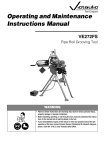
TM-VE106 3736 Rev_B.fm Page -1 Monday, May 9, 2005 12:02 PM
R
Operating and Maintenance
Instructions Manual
VE106 Groove-N-Go
Portable Pipe/Tubing Roll
Grooving Tool
Patented
WARNING
Failure to follow instructions and warnings could result in serious personal injury,
property damage, and/or product damage.
• Before operating or servicing the VE106 Groove-N-Go tool, read all instructions in
this manual and all warning labels on the tool.
• Wear safety glasses, hardhat, foot protection, and hearing protection.
• Save this operating and maintenance manual.
If you need additional copies of any literature, or if you have questions concerning the safe and proper operation of
this tool, contact Victaulic Tool Company, P.O. Box 31, Easton, PA 18044-0031, Phone: 1-800-PICK VIC, e-mail:
[email protected].
TM-VE106 3736 Rev_B.fm Page 1 Monday, May 9, 2005 12:02 PM
INDEX
Hazard Identification . . . . . . . . . . . . . . . . . 1
Operator Safety Instructions . . . . . . . . . . 2
Introduction . . . . . . . . . . . . . . . . . . . . . . . . 3
Receiving the Tool . . . . . . . . . . . . . . . . . . 3
VE106 Groove-N-Go
Container Contents . . . . . . . . . . . . . . . . 4
Power Requirements. . . . . . . . . . . . . . . . . 4
Extension Cord Requirements. . . . . . . . . 4
Tool Nomenclature . . . . . . . . . . . . . . . . . . 5
Tool Setup . . . . . . . . . . . . . . . . . . . . . . . . . 6
Pre-Operation Checks
and Adjustments . . . . . . . . . . . . . . . . . . . . 9
Grooving Rolls . . . . . . . . . . . . . . . . . . . . . 9
Pipe/Tubing Preparation . . . . . . . . . . . . . 9
Pipe/Tubing Lengths Suitable
for Grooving. . . . . . . . . . . . . . . . . . . . . . . 10
Short Pipe/Tubing Lengths . . . . . . . . . . 10
Long Pipe/Tubing Lengths . . . . . . . . . . . 11
Groove Diameter Stop Adjustment . . . . 12
Grooving Operation . . . . . . . . . . . . . . . . 15
Roll Changing . . . . . . . . . . . . . . . . . . . . . 19
Lower Roll/Main Shaft Removal . . . . . . . 19
Upper Roll Removal . . . . . . . . . . . . . . . 21
Upper Roll Installation . . . . . . . . . . . . . . 21
Lower Roll/Main Shaft Installation . . . . . 22
Maintenance. . . . . . . . . . . . . . . . . . . . . . . 23
Lubrication. . . . . . . . . . . . . . . . . . . . . . . 23
Parts Ordering Information . . . . . . . . . . . 25
Accessories . . . . . . . . . . . . . . . . . . . . . . . 25
VAPS112 Victaulic Adjustable
Pipe Stand . . . . . . . . . . . . . . . . . . . . . . 25
VAPS224 Victaulic Adjustable
Pipe Stand . . . . . . . . . . . . . . . . . . . . . . 25
Optional Rolls . . . . . . . . . . . . . . . . . . . . . 25
Troubleshooting . . . . . . . . . . . . . . . . . . . . 26
Tool Rating and Roll Selection . . . . . . . . 28
Standard and “ES” Rolls for Steel Pipe –
Color-Coded Black . . . . . . . . . . . . . . . 28
Standard Rolls for Schedule 5S
and 10S Stainless Steel Pipe –
Color-Coded Silver . . . . . . . . . . . . . . . 28
Rolls for CTS US Standard –
ASTM Drawn Copper Tubing –
Color-Coded Copper . . . . . . . . . . . . . . 29
Explanation of Critical Roll
Groove Dimensions . . . . . . . . . . . . . . . . . 30
Roll Groove Specifications . . . . . . . . . . . 31
Steel and Stainless Steel Pipe . . . . . . . . 31
Standard-Wall Pipe or Plastic-Coated
Pipe Joined with Style HP-70ES
EndSeal Couplings . . . . . . . . . . . . . . . 32
Copper Tubing to CTS US Standard –
ASTM B-88 and ASTM B-306 . . . . . . . 33
Facilities Locations . . . . . . . . . . . . . . . . . 34
HAZARD IDENTIFICATION
Definitions for identifying the various hazard levels are provided below.
This safety alert symbol indicates important safety messages. When you see this
symbol, be alert to the possibility of personal injury. Carefully read and fully understand the message that follows.
DANGER
• The use of the word “DANGER” identifies an immediate hazard with a likelihood of death or serious
personal injury if instructions, including recommended precautions, are not followed.
CAUTION
• The use of the word “CAUTION” identifies possible
hazards or unsafe practices that could result in personal injury and product or property damage if
instructions, including recommended precautions,
are not followed.
WARNING
• The use of the word “WARNING” identifies the presence of hazards or unsafe practices that could
result in death or serious personal injury if instructions, including recommended precautions, are not
followed.
VE106 Groove-N-Go Tool
NOTICE
• The use of the word “NOTICE” identifies special
instructions that are important but not related to
hazards.
1
TM-VE106 3736 Rev_B.fm Page 2 Monday, May 9, 2005 12:02 PM
OPERATOR SAFETY INSTRUCTIONS
The VE106 Groove-N-Go tool is designed only
for roll grooving pipe/tubing. Use of this tool
requires dexterity and mechanical skills, as
well as sound safety habits. Although this tool
is designed for safe, dependable operation, it
is impossible to anticipate all the combinations of circumstances that could result in an
accident. The following instructions are recommended for safe operation of this tool. The
operator is cautioned to always practice
“safety first” during each phase of use, including setup and maintenance. It is the responsibility of the owner, lessee, or user of this tool
to ensure that all operators read this manual
and fully understand the operation of this tool.
6. Prevent accidental startups. Be careful
not to depress the safety foot switch unintentionally.
Read this manual before operating or servicing this tool. Become familiar with the tool’s
operations, applications, and limitations. Be
particularly aware of its specific hazards.
Store this manual in a clean area where it is
always readily available. Additional copies of
this manual are available upon request
through the Victaulic Tool Company.
10. Keep visitors away from the immediate work area. All visitors should be kept a
safe distance from the equipment at all times.
1. This tool is designed ONLY for roll
grooving pipe/tubing sizes, materials, and
wall thicknesses listed in the "Tool Rating
and Roll Selection" section, starting on
page 28.
2. Avoid using the tool in dangerous
environments. Do not expose the tool to rain,
and do not use the tool in damp or wet locations. Do not use the tool on sloped or uneven
surfaces. Keep the work area well lit. Allow
sufficient space to operate the tool properly.
3. Ground the drive motor to protect the
operator from electric shock. Make sure the
drive motor is connected to an internally
grounded electrical source.
4. Prevent back injury. This tool is heavy.
When removing from or placing into a truck or
van, two people can lift the tool more safely
and faster than one.
5. Inspect the equipment. Before using
the tool, check all moveable parts for any
obstructions. Make sure tool components are
installed and adjusted properly.
2
7. Wear proper apparel. Do not wear loose
clothing, jewelry, or anything that can become
entangled in moving parts.
8. Wear protective items when working
with tools. Always wear safety glasses,
hardhat, foot protection, and hearing protection.
9. Stay alert. Do not operate the tool if you
are drowsy from medication or fatigue. Avoid
horseplay around the equipment.
11. When using this tool on an elevated
floor or platform, the area below must
remain clear of other personnel.
12. Keep work areas clean. Keep the work
area around the tool clear of any obstructions
that could limit the movement of the operator.
Clean up any oil or other spills.
13. Secure the work, machine, and accessories. Make sure the tool is stable. Refer to
the "Tool Setup" section on page 6.
14. Support the work. Support long pipe/
tubing lengths with a pipe stand that is
secured to the floor or the ground.
15. Operate the tool only with a safety foot
switch. The drive motor must be operated
with a safety foot switch that is located for
easy operator access. Never reach across
moving parts. If the tool does not contain a
safety foot switch, contact Victaulic.
16. Keep hands and tools away from
grooving rolls during the grooving operation. Grooving rolls can crush or cut fingers
and hands.
17. Do not reach inside the pipe/tubing
end during tool operation.
VE106 Groove-N-Go Tool
TM-VE106 3736 Rev_B.fm Page 3 Monday, May 9, 2005 12:02 PM
18. Do not over-reach. Maintain proper
footing and balance at all times. Make sure
the safety foot switch is easily accessible for
the operator.
19. Do not force the tool. Do not force the
tool or accessories to perform any functions
beyond their capabilities. Do not overload the
tool.
20. Do not abuse the safety foot switch
cord. Never yank the cord out of the receptacle. Keep the cord away from heat, oil, and
sharp objects.
21. Disconnect the power cord from the
electrical source before servicing the tool.
Only authorized personnel should attempt to
perform maintenance on the tool. Always disconnect the power cord from the electrical
source before servicing or adjusting the tool.
22. Maintain tools with care. Keep tools
clean at all times to ensure proper and safe
performance. Follow the instructions for lubricating tool components.
23. When tools are not in use, store them
in a dry, secure place.
24. Use only Victaulic replacement parts
and accessories. Use of any other parts may
result in a voided warranty, improper operation, and hazardous situations. Refer to the
“Parts Ordering Information” and “Accessories” sections on page 25.
25. Do not remove any labels from the
tool. Replace any damaged or worn labels.
INTRODUCTION
NOTICE
• Drawings and/or pictures in this manual may be
exaggerated for clarity.
• The tool, along with this operating and maintenance
instructions manual, contains trademarks, copyrights, and/or patented features that are the exclusive property of Victaulic Company.
The Victaulic VE106 Groove-N-Go tool is a
very portable, semi-automated, manual-feed
tool for roll grooving pipe/tubing to receive
Victaulic grooved pipe/tubing products. The
standard VE106 Groove-N-Go tool is supplied
with grooving rolls for 11/4 - 6-inch carbon
steel pipe. Rolls are marked with the size and
part number, and they are color coded to
identify the pipe material. For roll grooving to
other Victaulic specifications and materials,
refer to the "Tool Rating and Roll Selection"
section on page 28. Grooving rolls for other
specifications, sizes, and materials must be
purchased separately.
CAUTION
• This tool must be used ONLY for roll grooving pipe/
tubing designated in the “Tool Rating and Roll
Selection” section of this manual.
Failure to follow this instruction could overload the
tool, resulting in reduced tool life and/or damage to
the tool.
RECEIVING THE TOOL
VE106 Groove-N-Go tools are packed individually in sturdy containers. Upon receipt of the
tool, make sure all necessary parts are included. If any parts are missing, contact the Victaulic Tool Company.
VE106 Groove-N-Go Tool
3
TM-VE106 3736 Rev_B.fm Page 4 Monday, May 9, 2005 12:02 PM
VE106 GROOVE-N-GO
CONTAINER CONTENTS
POWER REQUIREMENTS
DANGER
• To reduce the risk of electric
shock, check the electrical
source for proper grounding.
• Before performing any maintenance on the tool, disconnect
the power cord from the electrical source.
Failure to follow these instructions could result in
death or serious personal injury.
Power must be supplied to the drive motor
through a safety foot switch to ensure safe
operation. Make sure the drive motor is
grounded properly in accordance with Article
250 of the National Electrical Code.
If an extension cord is required, refer to the
“Extension Cord Requirements” section
below for cord sizes.
Qty.
Description
1
Tool Head Assembly with Cart
3
Adjustable Legs (Secured in Leg
Storage Tubes of Cart)
1
Lower Roll/Main Shaft for 11/4 - 3-inch
Carbon Steel Pipe *
1
Safety-Foot-Switch Storage Box
1
Safety Foot Switch (Located Inside
Storage Box)
2
Operating and Maintenance Instructions
Manual
1
1
VE106 Groove-N-Go Repair Parts List
3/ -inch
8
Square-Drive Ratchet (10 inches
Long)
-
Spare Shear Pins
-
Depth Gauges for 11/4 - 6-inch Schedule
5, Schedule 10, and Schedule 40
Carbon Steel Pipe
1
3/ -inch
16
1
Go/No-Go Pipe Tape
1
11 oz. can of Dow Corning G-n
Mechanical Assembly Spray
Hex Key Allen Wrench
* The lower roll/main shaft for 4 – 6-inch carbon
steel pipe is installed in the head assembly
NOTE: Optional items, such as roll sets for grooving stainless steel pipe and copper tubing, may be
shipped separately.
4
EXTENSION CORD REQUIREMENTS
When pre-wired outlets are not available and
an extension cord must be used, it is important to use the proper cord size (i.e. Conductor Size American Wire Gauge). Cord size
selection is based upon tool rating (amps)
and cord length (feet). Cord sizes (gauges)
thinner than required will cause significant
voltage drop at the drive motor while the tool
is operating. Voltage drops may cause damage to the drive motor and can result in improper tool operation. NOTE: It is acceptable
to use a heavier cord size (gauge) than what
is required.
The required cord sizes (gauges) for cord
lengths up to and including 100 feet (30 m)
are listed in the table below. Use of extension
cords longer than 100 feet (30 m) must be
avoided.
Drive Motor
Rating
Volts (Amps)
25 feet
(8 m)
Cord Lengths
50 feet
(15 m)
100 feet
(31 m)
110
12 gauge
12 gauge
10 gauge
14 gauge
12 gauge
10 gauge
(12)
220
(6)
VE106 Groove-N-Go Tool
TM-VE106 3736 Rev_B.fm Page 5 Monday, May 9, 2005 12:02 PM
TOOL NOMENCLATURE
³⁄₈-inch
Square Hole for ³⁄₈-inch
Square-Drive Ratchet
Drive Socket
Overload
Device
NOTICE
Feed Screw
• Drawings and/or pictures in this manual may be
exaggerated for clarity.
• The tool, along with this operating and maintenance
instructions manual, contains trademarks, copyrights, and/or patented features that are the exclusive property of Victaulic Company.
Groove
Diameter
Stop
Body Nut
³⁄₈-inch
SquareDrive
Ratchet
Cart
Upper
Shaft
Lower Roll/
Main Shaft
Groove
Depth
Gauges
Drive Motor
Adjustable
Legs (3)
➀
Lower
Roll/Main
Shaft
Storage
Leg
Storage
Tubes
(3)
Safety-Foot-Switch
Storage Box
Safety Foot Switch
➁
➀
Failure to follow instructions
and warnings can result in
serious injury.
• Before installing, operating, or
servicing this tool, read and
understand the Operating
Instructions and all warning
labels on this tool.
• Always wear safety glasses and foot protection.
➁
Failure to follow instructions and warnings can result in
serious injury, property damage, or faulty installation.
• Before installing, operating, or servicing this tool, read and
understand the Operating Instructions and all warning
labels on this tool.
• Always wear safety glasses and foot protection.
If you have any questions about the safe operation of this tool,
contact Victaulic Tool Company, P.O. Box 31, Easton, PA 18044-0031,
610-559-3300.
If you have any questions about the safe operation of this tool,
contact Victaulic Tool Company, P.O. Box 31, Easton, PA
18044-0031, 610/559-3300
1532 Rev. A
R028226LBL
0567 Rev.A
VE106 Groove-N-Go Tool
R031272LAB
3/99
5
TM-VE106 3736 Rev_B.fm Page 6 Monday, May 9, 2005 12:02 PM
included. Refer to the "Receiving the Tool"
section on page 3.
TOOL SETUP
2. Select a location for the tool by taking
into consideration the following factors (refer
to the drawing below for overall dimensions):
WARNING
• DO NOT connect the tool to the electrical source
until instructed otherwise.
Accidental startup of the tool could result in serious
personal injury.
2a. The required power supply (verify the
voltage of the drive motor [110 volt or
220 volt])
2b. Adequate space to handle pipe/tubing
lengths
The standard VE106 Groove-N-Go tool is
intended for field or shop setup. Before grooving, the adjustable legs must be mounted
onto the tool.
2c. A firm and level surface for the tool and
pipe stand
1. Remove all components from the packaging, and make sure all necessary items are
2d. Adequate clearance around the tool
for adjustment and maintenance
F
A
G
H
E
C
D
B
Plan View
A
Front View
B
C
Side View
Dimensions – inches (millimeters)
D
E*
F
G
H
Tool Weight
lbs/kg
22.00
39.50
32.25
35.00
45.00
40.50
48.75
49.00
162
(558,8)
(1003,3)
(819,2)
(889,0)
(1143,0)
(1028,7)
(1238,3)
(1244,6)
73,5
* “E” dimension reflects maximum ram extension.
WARNING
• DO NOT lift the tool into the vertical (upright) position until the two front legs are installed.
• The tool will be top heavy until the third leg is
installed on the tool. Use caution to prevent the tool
from tipping over.
Failure to follow these instructions could result in
serious personal injury.
3. Make sure the tool is secure and in the
horizontal position (lying down) with the handle of the cart resting against the ground or
floor, as shown above.
6
VE106 Groove-N-Go Tool
TM-VE106 3736 Rev_B.fm Page 7 Monday, May 9, 2005 12:02 PM
4. Remove the legs from the leg storage
tubes. Install the two front legs by inserting
them into the sockets located on the underside of the tool head table. Make sure each
leg seats properly in the sockets. Rotate the
legs so that each foot points away from the
tool. Using a 1/2-inch wrench, tighten each 5/16
– 18 hex bolt to secure the legs to the tool.
5. Make sure the front legs are securely
fastened in the sockets. Lift/tilt the tool into the
vertical (upright) position, as shown above.
VE106 Groove-N-Go Tool
6. With the tool in the vertical (upright) position, install the third leg into the socket adjacent to the drive motor. Rotate the leg so that
the foot points away from the tool. Using a 1/2inch wrench, tighten the 5/16 – 18 hex bolt to
secure the leg to the tool.
7. Level the tool from front to back. NOTE:
The top of the tool head table is a good location to measure “level,” as shown above. If the
tool is not level, proceed with 7a.
7
TM-VE106 3736 Rev_B.fm Page 8 Monday, May 9, 2005 12:02 PM
7a. Loosen the hex bolts to adjust the legs
in or out, as required, to make the tool
level. Re-tighten all hex bolts after leveling the tool. Do not extend any of the
legs past the hex bolt. If this cannot be
accomplished, move the tool to a more
level surface, and repeat this step until
the tool is level.
DANGER
• To reduce the risk of electric
shock, check the electrical
source for proper grounding.
• Before performing any maintenance on the tool, disconnect
the power cord from the electrical source.
Failure to follow these instructions could result in
death or serious personal injury.
8a. Tighten the two trigger-lock switch
thumb screws to maintain this position.
WARNING
• DO NOT operate the drive motor without a safety
foot switch. If the tool does not contain a safety foot
switch, contact the Victaulic Tool Company.
Operating the tool without a safety foot switch could
result in serious personal injury.
Trigger
Trigger
Lock Tab
8. Make sure the drive-motor trigger switch
is depressed in the proper location. The trigger lock tab must push down on the drivemotor trigger switch.
9. Remove the safety foot switch from the
storage box.
9a. Plug the cord for the safety foot switch
into a grounded electrical outlet. Refer
to the "Power Requirements" section
on page 4. If an extension cord is
used, refer to the "Extension Cord Requirements" section on page 4 for
requirements.
8
VE106 Groove-N-Go Tool
TM-VE106 3736 Rev_B.fm Page 9 Monday, May 9, 2005 12:02 PM
PRE-OPERATION CHECKS AND
ADJUSTMENTS
Every Victaulic roll grooving tool is checked,
adjusted, and tested at the factory prior to
shipment. However, before attempting to
operate the tool, the following checks and
adjustments should be made to ensure proper tool operation.
WARNING
• Before making any tool adjustments, always disconnect the power cord from the electrical source.
Accidental startup of the tool could result in serious
personal injury.
10. Rotate the drive motor switch to the “L”
position to produce COUNTERCLOCKWISE
rotation of the lower roll/main shaft and pipe/
tubing, as shown above.
11. Depress the safety foot switch, check the
rotation of the lower roll/main shaft, and make
sure the tool is stable. If rotation is clockwise,
rotate the drive-motor switch to the opposite
position. If the tool wobbles, make sure the
legs are adjusted correctly and that the tool is
level on the floor. If the wobble persists, re-adjust the legs.
VE106 GROOVE-N-GO TOOL SETUP IS
NOW COMPLETE.
GROOVING ROLLS
Make sure the proper roll set is installed on
the tool for the pipe/tubing size and material
that will be grooved. Roll sets are marked with
the pipe/tubing size, part number, and they
are color coded for the pipe/tubing material.
Refer to the "Tool Rating and Roll Selection"
section, starting on page 28. If the proper rolls
are not installed on the tool, refer to the "Roll
Changing" section on page 19.
PIPE/TUBING PREPARATION
For proper tool operation and production of
grooves that are within Victaulic specifications, the following guidelines must be followed.
1. Victaulic recommends square-cut pipe/
tubing for use with grooved-end pipe/tubing
products. Square-cut pipe/tubing MUST be
used with FlushSeal® and EndSeal® gaskets.
Beveled-end pipe/tubing may be used, provided that the wall thickness is standard wall
(ANSI B36.10) or less and that the bevel
meets ANSI B16.25 (371/2º) or ASTM A-53
(30º). NOTE: Roll grooving beveled-end pipe/
tubing may result in unacceptable flare.
2. Raised internal and external weld beads
and seams must be ground flush with the
pipe/tubing surface 2 inches (50 mm) back
from the pipe/tubing ends.
VE106 Groove-N-Go Tool
9
TM-VE106 3736 Rev_B.fm Page 10 Monday, May 9, 2005 12:02 PM
3. All coarse scale, dirt, and other foreign
material must be removed from the interior
and exterior surfaces of the pipe/tubing ends.
NOTICE
• Grooved pipe/tubing nipples, shorter than those
listed in Table 1, are available from Victaulic.
CAUTION
• For maximum grooving roll life, remove foreign
material and loose rust from the interior and exterior
surfaces of the pipe/tubing ends. Rust is an abrasive material that will wear the surface of grooving
rolls.
Foreign material may interfere with or damage grooving rolls, resulting in distorted grooves and grooves
that are out of Victaulic specifications.
PIPE/TUBING LENGTHS
SUITABLE FOR GROOVING
The VE106 Groove-N-Go tool is capable of
grooving short pipe/tubing lengths without the
use of a pipe stand. Refer to the “Short Pipe/
Tubing Lengths” section on this page.
Pipe/tubing lengths longer than those listed in
Table 1 on this page (and up to 20 feet/6
meters) must be supported with a pipe stand.
Pipe/tubing lengths from 20 feet (6 meters) up
to double-random lengths (approximately 40
feet/12 meters) must be supported with two
pipe stands.
SHORT PIPE/TUBING LENGTHS
WARNING
Grooving rolls can crush or cut
fingers and hands.
• Never groove pipe/tubing that is
shorter than the recommended
lengths listed in this manual.
Table 1 shows the minimum and maximum
pipe/tubing lengths that can be grooved without the use of a pipe stand. Refer to the
"Grooving Operation" section, starting on
page 15, for instructions on how to groove
short pipe/tubing lengths. For pipe/tubing
longer than what is shown in Table 1, refer to
the "Long Pipe/Tubing Lengths" section on
page 11.
10
TABLE 1 – PIPE/TUBING LENGTHS
SUITABLE FOR GROOVING
Steel and Stainless
Steel Pipe Size
Actual
Nominal Pipe
Outside
Size
Diameter
inches or mm inches (mm)
Length – inches
(mm)
Minimum
Maximum
11/4
1.660
8
36
42,4
205
915
11/2
1.900
8
36
48,3
205
915
2
21/2
3
31/2
4
41/2
5
152,4 mm
6
2.375
8
36
60,3
205
915
2.875
8
36
73,0
205
915
3.500
8
36
88,9
205
915
4.000
8
36
101,6
205
915
4.500
8
36
114,3
205
915
5.000
8
32
127,0
205
815
5.563
8
32
141,3
205
815
6.000
10
30
152,4
255
765
6.625
10
28
168,3
255
715
If pipe/tubing is required that is shorter than
the minimum length listed in Table 1, shorten
the next-to-last piece so that the last piece is
as long (or longer) than the minimum length
specified. Refer to the example below.
EXAMPLE: A 20-foot, 4-inch (6,2-m) length of
6-inch diameter steel pipe is required to finish
a section, and only 20-foot (6,1-m) lengths are
available. Instead of roll grooving a 20-foot
(6,1-m) length of steel pipe and a 4-inch
(0,1-m) length of steel pipe, follow these
steps:
1. Refer to Table 1 on this page, and note
that for 6-inch diameter steel pipe, the minimum length that should be roll grooved is 10
inches (255 mm).
2. Roll groove a 19-foot, 6-inch (5,9-m)
length of pipe and a 10-inch (255-mm) length
VE106 Groove-N-Go Tool
TM-VE106 3736 Rev_B.fm Page 11 Monday, May 9, 2005 12:02 PM
of pipe. Refer to the “Long Pipe/Tubing
Lengths” section on this page.
LONG PIPE/TUBING
LENGTHS
e. Position the pipe stand at a distance
slightly beyond half the pipe/tubing length
from the tool. Refer to Figure 1 below.
¹⁄₂° to 1°
2 to 4 inches
(50 to 100 mm)
When roll grooving pipe/tubing that exceeds
the maximum length shown in Table 1, a roller-type pipe stand must be used. The rollertype pipe stand must be capable of handling
the weight of the pipe/tubing, while allowing
the pipe/tubing to rotate freely.
a. Make sure the tool is level. Refer to the
"Tool Setup" section on page 6 for leveling
requirements. Set the pipe stand height to
produce a 1/2 – 1° pitch on the pipe away from
the tool (see Figure 1). This will help promote
tracking and reduce pipe end flare.
b. When flare is excessive, right-to-left
tracking must be kept to a minimum. It may be
necessary to use less than 1/2º for the tracking
angle (see Figure 2).
Pipe
Centerline
10 ft + 1 ft - 0
(3m + 0,3m - 0)
20-foot (6-meter)
Length of Pipe
Pipe Angle
Exaggerated for
Clarity
Figure 1 - SUPPORT OF PIPE
f.
Position the pipe stand approximately 0
to 1/2º to the left for the tracking angle. Refer to
Figure 2 below.
Tool
Centerline
0° to ¹⁄₂° Max.
0-inches to 2-inches Max.
(0-mm to 50-mm Max.)
c.
Installation of couplings on pipe/tubing
that exceeds the maximum allowable flare
may prevent pad-to-pad closure of the housings and/or may cause damage to the
coupling gasket. Refer to the applicable “Roll
Groove Specifications” table for details.
d. If the tool is properly set up in a level
position, but the back end of the pipe/tubing
is higher than the end being grooved, the
pipe/tubing may not track. As a result, excessive flare may occur on the pipe/tubing end.
Refer to the "Tool Setup" section, starting on
page 6, and Figures 1 and 2 for tool setup and
pipe/tubing positioning requirements.
Tool
Centerline
(Level)
Pipe
Centerline
Pipe Angle
Exaggerated for
Clarity
20-foot (6-meter)
Length of Pipe
Figure 2 - TRACKING ANGLE
NOTICE
• Figure 1 shows a typical pipe stand
• Victaulic offers several pipe stands, such as the
VAPS112 and VAPS224. The VAPS112 is suitable for
3
/4 – 12-inch sizes. The VAPS224 is suitable for 2– 24inch sizes. Refer to the "Accessories" section on
page 25.
• For additional information about the pipe stands,
refer to the Operating and Maintenance Instructions
Manual included with the pipe stand.
VE106 Groove-N-Go Tool
11
TM-VE106 3736 Rev_B.fm Page 12 Monday, May 9, 2005 12:02 PM
GROOVE DIAMETER STOP
ADJUSTMENT
The groove diameter stop must be adjusted
for each pipe/tubing size or change in wall
thickness. The groove diameter, which is
identified as the “C” dimension, is listed under
the "Roll Groove Specifications" section, starting on page 31. In addition, a label is affixed
to the tool, which lists the “C” dimensions.
NOTICE
• To perform the following adjustments, use several
short, scrap sections of pipe/tubing that are the
proper material, diameter, and thickness to be
grooved. Make sure the scrap sections meet the
length requirements listed in Table 1 – Pipe/Tubing
Lengths suitable for grooving on page 10.
To achieve the proper diameter:
2a. Back off the groove-diameter stop by
loosening the clamping screw with the
supplied 3/16-inch hex key allen
wrench. Turn the groove-diameter
stop counter-clockwise several turns.
1. Determine the diameter and thickness of
the pipe/tubing to be grooved.
2. Using the 3/8-inch square-drive ratchet
(provided), retract (turn counter-clockwise)
the feed screw/upper roll until the pipe/tubing
can be slipped completely over the lower roll.
3. Insert a length of pipe/tubing that is the
correct size and thickness onto the lower roll.
12
VE106 Groove-N-Go Tool
TM-VE106 3736 Rev_B.fm Page 13 Monday, May 9, 2005 12:02 PM
Pipe
Lower Roll
Backstop
Flange
4. Make sure the pipe/tubing end contacts
the lower-roll backstop flange completely.
5. Continue supporting the pipe manually.
Using the 3/8-inch square-drive ratchet, advance (turn clockwise) the feed screw to
place the upper roll into light contact with the
pipe/tubing.
6. Locate the groove-depth gauges on the
tool. Remove the wing nut from the gauge
retainer, and select the proper groove-depth
gauge for the pipe size being grooved.
7. Using the groove-depth gauge as a
“feeler gauge” between the groove-diameter
stop and body nut, adjust the groove-diameter stop until it contacts the groove-depth
gauge, as shown above.
7a. Using the 3/16-inch hex key allen
wrench, tighten the screw on the
groove-diameter stop to maintain the
adjustment made in the previous step.
VE106 Groove-N-Go Tool
13
TM-VE106 3736 Rev_B.fm Page 14 Monday, May 9, 2005 12:02 PM
8. Replace the groove-depth gauge onto
the gauge retainer. Re-install and tighten the
wing nut.
WARNING
Grooving rolls can crush or cut
fingers and hands.
• Before making any tool adjustments, always disconnect the
power cord from the electrical
source.
• Loading and unloading pipe/tubing will place your
hands close to the rollers. Keep hands away from
the grooving rolls during operation.
• Never reach inside the pipe/tubing end or across the
tool or pipe/tubing during operation.
• Always groove pipe/tubing in a COUNTERCLOCKWISE direction only.
• Never groove pipe/tubing that is shorter than the
recommended lengths listed in this manual.
• Never wear loose clothing, loose gloves, or anything
that can become entangled in moving parts.
9. Prepare a trial groove. Refer to the
"Grooving Operation" section, starting on
page 15.
10. After a trial groove is prepared and the
pipe/tubing is removed from the tool, carefully
check the groove diameter (“C” dimension).
Refer to the "Roll Groove Specifications" section, starting on page 31. The pipe tape, supplied with the tool, is the best method for
checking the “C” dimension. In addition, a
vernier caliper or narrow-land micrometer can
be used to check this dimension at two locations (90º apart) around the groove. The average reading must be within the required
groove diameter specification.
CAUTION
• The “C” dimension (groove diameter) must conform
to Victaulic specifications to ensure proper joint
performance.
Failure to follow this instruction could cause joint
failure, resulting in personal injury and/or property
damage.
11. If the groove diameter (“C” dimension) is
not within Victaulic specifications, the diameter stop must be adjusted.
11a.To DECREASE the groove diameter
(increase groove depth), turn the diameter stop counterclockwise (when
viewed from above the tool).
11b.To INCREASE the groove diameter
(decrease groove depth), turn the diameter stop clockwise (when viewed
from above the tool).
14
VE106 Groove-N-Go Tool
TM-VE106 3736 Rev_B.fm Page 15 Monday, May 9, 2005 12:02 PM
NOTE: A quarter-turn either way will change
the groove diameter adjustment by approximately 0.013 inch (0,3 mm) or 0.051 inch (1,3
mm) per full turn.
12. Prepare another trial groove, and check
the groove diameter (“C” dimension), as
described in step 10. Repeat these steps, as
necessary, until the groove diameter is within
specification.
GROOVING OPERATION
DANGER
• To reduce the risk of electric
shock, check the electrical
source for proper grounding.
• Before operating the tool,
review the"Operator Safety
Instructions" section on page 2
of this manual.
Failure to follow these instructions could result in
death or serious personal injury.
CAUTION
• This tool must be used ONLY for roll grooving pipe/
tubing designated in the “Tool Rating and Roll
Selection” section of this manual.
Failure to follow this instruction could overload the
tool, resulting in reduced tool life and/or damage to
the tool.
1. Before grooving, make sure all instructions in the previous sections of this manual
have been followed.
2. Plug the safety foot switch into an internally grounded electrical source. Make sure
the safety foot switch and drive motor are
grounded.
VE106 Groove-N-Go Tool
15
TM-VE106 3736 Rev_B.fm Page 16 Monday, May 9, 2005 12:02 PM
5. Using the 3/8-inch square-drive ratchet
(provided), rotate the feed screw counterclockwise to move the upper roll to the full up
position.
WARNING
3. Set the switch on the drive motor to produce counterclockwise rotation of the lower
roll/main shaft and pipe/tubing when viewed
from the front of the tool. Placing the switch in
the “L” position will produce counterclockwise
rotation of the lower roll/main shaft and pipe/
tubing.
WARNING
• The drive motor must be operated with a safety foot
switch. If the drive motor does not contain a safety
foot switch, contact the Victaulic Tool Company.
Operating the tool without a safety foot switch could
result in serious personal injury.
Grooving rolls can crush or cut
fingers and hands.
• Before making any tool adjustments, always disconnect the
power cord from the electrical
source.
• Loading and unloading pipe/tubing will place your
hands close to the rollers. Keep hands away from
the grooving rolls during operation.
• Never reach inside the pipe/tubing end or across the
tool or pipe/tubing during operation.
• Always groove pipe/tubing in a COUNTERCLOCKWISE direction only.
• Never groove pipe/tubing that is shorter than the
recommended lengths listed in this manual.
• Never wear loose clothing, loose gloves, or anything
that can become entangled in moving parts.
4. Make sure the tool is operational by
depressing the safety foot-switch pedal. The
lower roll/main shaft must turn COUNTERCLOCKWISE when viewed from the front of
the tool. Remove foot from the safety foot
switch.
16
VE106 Groove-N-Go Tool
TM-VE106 3736 Rev_B.fm Page 17 Monday, May 9, 2005 12:02 PM
6. Insert a length of pipe/tubing that is the
correct size and thickness onto the lower roll.
8. Rotate the feed screw clockwise to
bring the upper roll into firm contact with the
pipe/tubing. Continue to support the pipe, or
use a pipe stand for long pipe/tubing lengths.
Refer to the "Long Pipe/Tubing Lengths" section on page 11.
9.
Remove hands from the pipe/tubing.
Pipe
Lower Roll
Backstop
Flange
7. Make sure the pipe/tubing end contacts
the lower-roll backstop flange completely.
10. For long pipe/tubing lengths supported
with a pipe stand, make sure the pipe/tubing
is pitched and positioned properly. Refer to
the "Long Pipe/Tubing Lengths" section on
page 11.
VE106 Groove-N-Go Tool
17
TM-VE106 3736 Rev_B.fm Page 18 Monday, May 9, 2005 12:02 PM
12. Continue the grooving process until the
groove diameter stop makes firm contact with
the top of the body nut.
13. Continue to rotate the pipe/tubing for one
to three revolutions to ensure groove completion.
14. Release the safety foot switch pedal, and
withdraw foot from the safety foot switch.
WARNING
• DO NOT place hands inside the pipe/tubing end or in
the area of the grooving rolls while the pipe/tubing
is still rotating.
Failure to follow this instruction could result in serious personal injury.
15. If a short length of pipe/tubing is in the
tool, manually support the pipe/tubing.
11. Depress and hold down the safety footswitch pedal. The pipe/tubing will begin to
rotate counterclockwise. As the pipe/tubing
rotates, begin the grooving process by rotating the feed screw clockwise slowly with the
3/ -inch square-drive ratchet. Make sure the
8
pipe/tubing remains against the lower-roll
backstop flange. If the pipe/tubing does not
remain against the lower-roll backstop flange,
release the safety foot switch, and re-position
the pipe/tubing.
16. To release the pipe/tubing, retract the
upper roll by turning the feed screw counterclockwise. Remove the pipe/tubing from the
tool.
NOTICE
• The groove diameter must be within specification
for the diameter and wall thickness of pipe/tubing.
The groove diameter should be checked and
adjusted, as necessary, to ensure grooves remain
within specification.
NOTICE
• Groove light-wall pipe at a moderate rate by forming
grooves uniformly in 5 to 10 pipe rotations.
• Schedule 40 pipe requires more revolutions to reach
the proper groove diameter.
• A shear pin is used to connect the drive socket to
the feed screw. If excessive force is applied to the
3
/8-inch square-drive ratchet, the spring pin will
shear and prevent damaging forces from being
applied to tool components.
• The tool is designed to accommodate normal grooving forces. Therefore, shearing the pin should not
occur normally. However, if a pin shears, determine
the cause by referring to the "Troubleshooting" section on page 26. Correct the problem, and replace
the sheared pin with a spare pin supplied with the
tool.
18
VE106 Groove-N-Go Tool
TM-VE106 3736 Rev_B.fm Page 19 Monday, May 9, 2005 12:02 PM
ROLL CHANGING
WARNING
• Before making any tool adjustments, always disconnect the power cord from the electrical source.
Accidental startup of the tool could result in serious
personal injury.
The VE106 Groove-N-Go roll grooving tool is
designed with rolls to accommodate several
pipe/tubing sizes, which eliminates the need
for frequent roll changes.
In addition, different pipe/tubing materials
may require different rolls. For proper roll
selection, refer to the "Tool Rating and Roll Selection" section, starting on page 28.
LOWER ROLL/MAIN SHAFT
REMOVAL
When preparing to groove stainless steel
pipe, copper tubing, or “ES” grooves, the lower roll/main shaft for carbon steel pipe must
be removed.
In preparation for either copper tubing or “ES”
grooves, the carbon steel upper roll must also
now be removed (see "Upper Roll Removal"
section on page 21 and "Upper Roll Installation" section on page 21). The upper roll must
be installed first prior to locating the lower roll
shaft in the tool body.
2. Loosen and remove the 3/8-inch hex bolt
and lock washer at the rear of the shaft.
WARNING
DO NOT strike the roll with a hammer or other blunt object. Striking
the roll can cause fragmentation,
resulting in serious personal injury.
• Always wear safety glasses.
• Use only the supplied punch for
roll removal.
• Never strike the roll directly for
any reason.
1. Raise the upper roll arm to its maximum
position by rotating the feed screw counterclockwise.
VE106 Groove-N-Go Tool
19
TM-VE106 3736 Rev_B.fm Page 20 Monday, May 9, 2005 12:02 PM
5. Using a punch and hammer (these tools
are not furnished), tap the lower roll/main
shaft out from the rear of the tool, as shown
above.
3. Remove the drive key from the rear of the
shaft.
6. Pull the lower roll/main shaft out from the
front of the tool head. Using a soft cloth,
remove any debris and excess grease from
the lower roll/main shaft.
4. Store the drive key, hex bolt, and lock
washer into the safety-foot-switch storage box
to prevent the items from being misplaced.
7. Store the lower roll/main shaft in a holder
located on the tool cart.
8. Follow the "Lower Roll/Main Shaft Installation" section on page 22.
20
VE106 Groove-N-Go Tool
TM-VE106 3736 Rev_B.fm Page 21 Monday, May 9, 2005 12:02 PM
UPPER ROLL REMOVAL
The same upper roll is used for standard
grooving of carbon steel pipe and stainless
steel pipe.
When preparing to groove copper tubing or
“ES” grooves, the upper roll for carbon steel/
stainless steel pipe must be removed and the
appropriate roll must be installed.
4. Follow the “Upper Roll Installation” section shown below.
UPPER ROLL INSTALLATION
1. Select the proper upper roll for the pipe
size and material to be grooved. Refer to the
"Tool Rating and Roll Selection" section on
page 28.
NOTICE
• The lower roll/main shaft must be removed prior to
removing the upper roll from the upper roll shaft/
arm casting.
2. Position the upper roll in the pocket of
the arm casting. NOTE: The flange portion of
the upper roll must face toward the rear of the
tool, as shown above.
1. Using a 3/32-inch allen wrench (not supplied) , loosen the set screw located on the
top, front portion of the arm casting.
3. Insert the upper shaft into the arm casting and upper roll.
2. Prepare to support the upper roll while
sliding the upper shaft out of the arm casting.
4. Tighten the set screw to secure the
upper shaft in position. Make sure the upper
roll rotates freely.
3. Remove the upper roll. Store the upper
roll in the safety-foot-switch storage box.
VE106 Groove-N-Go Tool
5. Lower the arm casting, and make sure
the upper roll aligns properly with the lower
roll/main shaft.
21
TM-VE106 3736 Rev_B.fm Page 22 Monday, May 9, 2005 12:02 PM
LOWER ROLL/MAIN SHAFT
INSTALLATION
1. Select the proper lower roll/main shaft for
the pipe size and material to be grooved. Refer to the "Tool Rating and Roll Selection" section on page 28.
NOTICE
• Upper roll installation must be complete prior to
proceeding with lower roll/main shaft installation.
4. Install the lower roll/main shaft into the
tool head. While maintaining a grip on the
knurled end (lower roll) of the main shaft,
make sure the flats on the drive end of the
main shaft align with the flats in the drive
motor.
2. Apply graphite spray (supplied) to the
lower roll/main shaft bore, as shown above.
5. Seat the drive key into the rear of the lower roll/main shaft.
3. Apply graphite spray to the main shaft,
as shown above.
22
VE106 Groove-N-Go Tool
TM-VE106 3736 Rev_B.fm Page 23 Monday, May 9, 2005 12:02 PM
LUBRICATION
6. Install the lock washer, and tighten the
3/ -inch hex bolt to retain the drive key.
8
MAINTENANCE
DANGER
• Before performing any maintenance on the tool, disconnect
the power cord from the electrical source.
Failure to follow this instruction
could result in death or serious
personal injury.
This section provides information about keeping tools in proper operating condition and
guidance for making repairs, when necessary. Preventive maintenance during operation will pay for itself in repair and operating
savings.
1. After every 2 hours of operation, apply a
No. 2EP lithium-base grease to the feed
screw. Apply the grease by hand to the screw
threads or through the grease fitting located
at the feed screw. Keep the feed screw lubricated to ensure a long service life.
Replacement parts must be ordered from
Victaulic Tool Company to ensure proper and
safe operation of the tool.
VE106 Groove-N-Go Tool
23
TM-VE106 3736 Rev_B.fm Page 24 Monday, May 9, 2005 12:02 PM
2. Apply grease underneath the toggle
pad.
4. Apply grease to the locations where the
roll arm slides against the tool body.
5. After every 8 hours of operation, apply
grease to the grease fitting of the upper roll
shaft.
3. Apply grease to the ball-and-socket joint
of the toggle pad.
24
VE106 Groove-N-Go Tool
TM-VE106 3736 Rev_B.fm Page 25 Monday, May 9, 2005 12:02 PM
PARTS ORDERING
INFORMATION
VAPS224 VICTAULIC ADJUSTABLE
PIPE STAND
When ordering parts, the following information
is required for the Victaulic Tool Company to
process the order and send the correct
part(s). Request the RP-VE106 Repair Parts
List for detailed drawings and parts listings.
1.
Tool Model Number – VE106
2. Tool Serial Number – The serial number
is stamped onto the tool body
3. Quantity, Part Number, and Description
– For example, (1), R006106PLT, Drive Key
4. Where to Send the Part(s) – Company
name and address
5.
To Whose Attention to Send the Part(s)
6.
Purchase Order Number
Order parts from the Victaulic Tool Company
at the address listed in this manual.
ACCESSORIES
VAPS112 VICTAULIC ADJUSTABLE
PIPE STAND
The Victaulic VAPS224 contains features that
are similar to the VAPS112, but it is suitable for
2 – 24-inch pipe sizes. Contact the Victaulic
Tool Company for details.
OPTIONAL ROLLS
The following optional rolls are available for
purchase. Contact the Victaulic Tool Company for details.
• Lower Roll/Main Shaft for Grooving 11/4 - 6inch Schedule 5S and 10S Stainless Steel
Pipe (NOTE: The same upper roll is used for
grooving carbon steel pipe and stainless
steel pipe)
• Lower Roll/Main Shaft and Upper Roll for
Grooving 2 – 8-inch ASTM Drawn Copper
Tubing to CTS US Standard
• Lower Roll/Main Shaft and Upper Roll for 2
– 3-inch “ES” Grooves
• Lower Roll/Main Shaft and Upper Roll for 4
– 6-inch “ES” Grooves
The Victaulic VAPS112 is a portable, adjustable, roller-type pipe stand that contains four
legs for additional stability. Ball transfer rollers, adjustable for 3/4 - 12-inch pipe, accommodate linear and rotational movement. The
turnstile design permits ease of grooving for
both pipe ends. Contact Victaulic Tool Company for details.
VE106 Groove-N-Go Tool
25
TM-VE106 3736 Rev_B.fm Page 26 Monday, May 9, 2005 12:02 PM
TROUBLESHOOTING
Problem
Possible Cause
Pipe/tubing will not
Incorrect pipe/tubing
stay in grooving rolls. positioning of long pipe/tubing
length.
Solution
Refer to the "Long Pipe/Tubing Lengths"
section on page 11.
Lower roll/main shaft and pipe/ Turn the drive motor switch to the opposite
tubing are not rotating
rotation position.
counterclockwise.
Pipe/tubing stops
rotating during
grooving.
Rust or dirt buildup is present
on the lower roll.
Remove rust or dirt accumulation from the
lower roll with a stiff wire brush.
Rust or dirt is excessively
heavy inside the pipe/tubing
end.
Remove heavy rust and dirt from inside the
pipe/tubing end.
Worn lower roll.
Inspect the lower roll for worn knurls.
Replace the lower roll/main shaft if
excessive wear is present.
The circuit breaker/GFI has
tripped or a fuse has blown out
on the electrical circuit that
supplies the power drive.
Test/reset the jobsite GFI/breaker, or
replace the fuse.
The trigger-lock switch clamp
is loose.
Tighten the trigger-lock switch thumb
screws.
Incorrect pipe/tubing support
positioning of long pipe/tubing
length. Pipe/tubing is “overtracking.”
Move the pipe support to the right. Refer to
the "Long Pipe/Tubing Lengths" section on
page 11.
Pipe/tubing end is not cut
square.
Cut the pipe/tubing end squarely.
Pipe/tubing is rubbing
excessively on the lower-roll
backstop flange.
Remove the pipe/tubing from the tool, and
apply a light coating of grease to the face of
the lower-roll backstop flange, as needed.
During grooving,
loud thumps or
bangs occur
approximately once
every revolution of
the pipe/tubing.
Pipe/tubing has a pronounced
weld seam.
Grind the raised welds flush with the interior
and exterior pipe/tubing surfaces 2 inches
(50 mm) back from the pipe/tubing end.
Pipe/tubing flare is
excessive.
Pipe/tubing support adjusted
too high for long pipe/tubing
length.
Refer to the "Long Pipe/Tubing Lengths"
section on page 11.
While grooving, loud
squeaks echo
through the pipe/
tubing.
Tool is tilted forward (out of
Refer to the "Tool Setup" section on page 6.
level) while grooving long pipe/
tubing length.
The tool will not
groove the pipe/
tubing.
26
Incorrect pipe/tubing support
positioning.
Move the pipe support to the right. Refer to
the "Long Pipe/Tubing Lengths" section on
page 11.
Pipe/tubing is beyond the wall
thickness capacity of the tool,
or the pipe/tubing material is
too hard.
Refer to the "Tool Rating and Roll Selection"
section, starting on page 28.
VE106 Groove-N-Go Tool
TM-VE106 3736 Rev_B.fm Page 27 Monday, May 9, 2005 12:02 PM
Shear pin broke.
Pipe/tubing grooves
do not meet Victaulic
specifications.
The “A” Gasket Seat
or “B” Groove Width
dimensions do not
meet Victaulic
specifications.
Rolls were being fed too fast.
Replace the shear pin, and groove the
pipe/tubing at a slower rate.
Pipe/tubing is beyond the wall
thickness capacity of the tool,
or the pipe/tubing material is
too hard.
Replace the pin, and groove pipe/tubing
that is within the capacity of the tool. Refer
to the "Tool Rating and Roll Selection"
section, starting on page 28.
The feed mechanism is
binding, damaged, or
insufficiently lubricated.
Repair and lubricate the feed mechanism,
as required.
Groove diameter stop is not
adjusted correctly.
Refer to the "Groove Diameter Stop
Adjustment" section on page 12.
Pipe/tubing is beyond the wall
thickness capacity of the tool,
or the pipe/tubing material is
too hard.
Refer to the "Tool Rating and Roll Selection"
section, starting on page 28.
Upper roll bearing is not
lubricated sufficiently.
Refer to the "Maintenance" section, starting
on page 23.
Incorrect upper roll, lower roll,
or both installed on the tool.
Install the correct rolls. Refer to the "Tool
Rating and Roll Selection" section, starting
on page 28.
VE106 Groove-N-Go Tool
27
TM-VE106 3736 Rev_B.fm Page 28 Monday, May 9, 2005 12:02 PM
TOOL RATING AND ROLL SELECTION
STANDARD AND “ES” ROLLS FOR STEEL PIPE – COLOR-CODED BLACK
Pipe Size
Actual Outside
Nominal
Diameter
Size inches
inches (mm)
11/4
1
1 /2
2
1
2 /2
3
4
41/2
5
6
Dimensions – inches/millimeters
Steel Pipe Wall Thickness *
Minimum
Maximum
1.660
0.065
0.140
42,4
1,7
3,6
1.900
0.065
0.145
48,3
1,7
3,7
2.375
0.065
0.154
60,0
1,7
3,9
2.875
0.083
0.203
73,0
2,1
5,2
3.500
0.083
0.216
88,9
2,1
5,5
4.500
0.083
0.237
114,3
2,1
6,0
5.000
0.095
0.237
127,0
2,4
6,0
5.563
0.109
0.258
141,3
2,8
6,6
6.625
0.109
0.280
168,3
2,8
7,1
Standard
Roll Part Numbers
“ES” Roll Part
Numbers
Lower Roll
R912106L03
Upper Roll
R912106U06
Lower Roll
RZ02106L03
Upper Roll
RZ02106U03
Lower Roll
R904106L06
Lower Roll
RZ04106L06
Upper Roll
R912106U06
Upper Roll
RZ04106U06
Notes:
* Maximum ratings on steel are limited to pipe of a Brinnel Hardness Number (BHN) of 180 BHN and less
The wall thicknesses listed are nominal minimum and maximum
In addition, the following pipe sizes may be roll grooved: 76,1 mm; 108,0 mm; 127,0 mm; 133,0 mm; 139,7
mm; 152,4 mm; 159,0 mm; and 165,1 mm. Contact Victaulic Tool Company for details.
STANDARD ROLLS FOR SCHEDULE 5S AND 10S STAINLESS STEEL PIPE –
COLOR-CODED SILVER
Pipe Size
Nominal
Size inches
Actual Outside
Diameter
inches (mm)
Dimensions – inches/millimeters
Stainless Steel Pipe Wall Thickness *
Minimum for
Maximum for
Schedule 5S
Schedule 10S
11/4
1.660
0.065
42,4
1,7
2,8
11/2
1.900
0.065
0.109
2
21/2
3
4
5
6
RX Roll
Part Numbers
0.109
48,3
1,7
2,8
2.375
0.065
0.109
60,0
1,7
2,8
2.875
0.083
0.120
73,0
2,1
3,0
3.500
0.083
0.120
88,9
2,1
3,0
4.500
0.083
0.120
114,3
2,1
3,0
5.563
0.109
0.134
141,3
2,8
3,4
6.625
0.109
0.134
168,3
2,8
3,4
Lower Roll
RX12106L06
Upper Roll
R912106U06
Notes:
* Types 304/304L and 316/316L stainless steel pipe
The wall thicknesses listed are nominal minimum and maximum
In addition, the following pipe sizes may be roll grooved: 76,1 mm; 108,0 mm; 133,0 mm; 139,7 mm; 152,4
mm; 159,0 mm; and 165,1 mm. Contact Victaulic Tool Company for details.
28
VE106 Groove-N-Go Tool
TM-VE106 3736 Rev_B.fm Page 29 Monday, May 9, 2005 12:02 PM
ROLLS FOR CTS US STANDARD – ASTM DRAWN COPPER TUBING –
COLOR-CODED COPPER
Tube Size
Nominal
Size inches
Actual Outside
Diameter
inches (mm)
2
21/2
3
4
5
6
Dimensions – inches/millimeters
Copper Tubing Wall Thickness *
Minimum
Maximum
2.125
0.042
0.083
54,0
1,1
2,1
2.625
0.065
0.095
66,7
1,7
2,4
3.125
0.045
0.109
79,4
1,1
2,8
4.125
0.058
0.134
104,8
1,5
3,4
5.125
0.072
0.160
130,2
1,8
4,1
6.125
0.083
0.192
155,6
2,1
4,9
Copper Roll
Part Numbers
Lower Roll
RR02106L06
Upper Roll
RR02106U06
* ASTM B306, Type DWV and ASTM B88, Types K, L, M copper tubing
The wall thicknesses listed are nominal minimum and maximum
VE106 Groove-N-Go Tool
29
TM-VE106 3736 Rev_B.fm Page 30 Monday, May 9, 2005 12:02 PM
EXPLANATION OF CRITICAL ROLL GROOVE DIMENSIONS
B
A B
OD
T
C
D
Exaggerated for clarity
Standard Roll Groove
Outside Diameter (“OD”) Dimension – The outside diameter of roll grooved pipe must not vary
from the specifications listed in the following tables. The maximum allowable tolerance from
square-cut pipe ends is 0.030 inch (0,8 mm) for 11/4 - 3-inch sizes and 0.045 inch (1,1 mm) for
4 – 6-inch sizes. This is measured from the true square line.
“A” Dimension – The “A” dimension, or the distance from the pipe end to the groove, identifies
the gasket seating area. This area must be free from indentations, projections, and roll marks from
the pipe end to the groove to provide a leak-tight seal for the gasket.
“B” Dimension – The “B” dimension, or groove width, controls expansion and angular deflection
by the distance it is located from the pipe and its width in relation to the housings’ “key” width.
“C” Dimension – The “C” dimension is the proper diameter at the base of the groove. This
dimension must be within the diameter’s tolerance and concentric with the OD for proper
coupling fit. The groove must be of uniform depth for the entire pipe circumference.
“D” Dimension – The “D” dimension is the normal depth of the groove and is a reference for a
“trial groove” only. Variations in pipe OD affect this dimension and must be altered, if necessary,
to keep the “C” dimension within tolerance. This groove must conform to the “C” dimension.
“F” Dimension (Standard Roll Groove Only) – Maximum allowable pipe-end flare diameter is
measured at the extreme pipe-end diameter.
“T” Dimension – The “T” dimension is the lightest grade (minimum, nominal wall thickness) of
pipe that is suitable for roll grooving (except for PVC pipe).
30
VE106 Groove-N-Go Tool
VE106 Groove-N-Go Tool
159,0 mm
152,4 mm
5
139,7 mm
133,0 mm
41/2
4
108,0 mm
3
76,1 mm
2 /2
1
2
11/2
11/4
5.050
128,3
5.303
134,7
5.556
141,1
5.619
142,7
6.056
153,8
6.313
160,4
5.000
127,0
5.250
133,0
5.500
139,7
5.563
141,3
6.000
152,4
6.250
159,0
107,2
115,4
88,1
4.219
89,8
4.293
88,9
4.250
114,3
75,4
3.469
77,0
3.535
76,1
3.500
109,0
72,3
2.970
73,8
3.030
73,0
3.000
4.545
59,7
2.846
60,9
2.904
60,3
2.875
108,0
47,8
2.351
48,7
2.399
48,3
2.375
4.500
1.881
1.919
1.900
158,0
6.219
151,6
5.969
140,5
5.532
138,9
5.469
132,6
5.219
126,2
4.969
113,5
4.469
41,8
42,6
1.644
1.676
42,4
Pipe Outside Diameter
Max.
Min.
1.660
Nominal Size Actual OD
inches or mm inches (mm)
Pipe Size
STEEL AND STAINLESS STEEL PIPE
15,9
0.625
15,9
0.625
15,9
0.625
15,9
0.625
15,9
0.625
15,9
0.625
15,9
0.625
15,9
0.625
15,9
0.625
15,9
0.625
15,9
0.625
15,9
0.625
15,9
0.625
15,9
0.625
16,7
0.656
16,7
0.656
16,7
0.656
16,7
0.656
16,7
0.656
16,7
0.656
16,7
0.656
16,7
0.656
16,7
0.656
16,7
0.656
16,7
0.656
16,7
0.656
16,7
0.656
16,7
0.656
15,1
0.594
15,1
0.594
15,1
0.594
15,1
0.594
15,1
0.594
15,1
0.594
15,1
0.594
15,1
0.594
15,1
0.594
15,1
0.594
15,1
0.594
15,1
0.594
15,1
0.594
15,1
0.594
8,7
0.344
8,7
0.344
8,7
0.344
8,7
0.344
8,7
0.344
8,7
0.344
8,7
0.344
8,7
0.344
8,7
0.344
8,7
0.344
8,7
0.344
8,7
0.344
7,1
0.281
7,1
0.281
9,5
0.375
9,5
0.375
9,5
0.375
9,5
0.375
9,5
0.375
9,5
0.375
9,5
0.375
9,5
0.375
9,5
0.375
9,5
0.375
9,5
0.375
9,5
0.375
7,9
0.312
7,9
0.312
8,0
0.313
8,0
0.313
8,0
0.313
8,0
0.313
8,0
0.313
8,0
0.313
8,0
0.313
8,0
0.313
8,0
0.313
8,0
0.313
8,0
0.313
8,0
0.313
6,4
0.250
6,4
0.250
Dimensions – inches (millimeters)
Gasket Seat “A”
Groove Width “B”
Basic
Max.
Min.
Basic
Max.
Min.
ROLL GROOVE SPECIFICATIONS
153,2
6.032
148,1
5.830
137,0
5.395
135,5
5.334
129,1
5.084
122,8
4.834
110,1
4.334
103,7
4.084
84,9
3.344
72,3
2.845
69,1
2.720
57,2
2.250
45,1
1.775
39,0
1.535
152,5
6.002
147,5
5.808
136,5
5.373
135,0
5.314
128,6
5.064
122,3
4.814
109,6
4.314
103,2
4.064
84,5
3.326
71,8
2.827
68,6
2.702
56,8
2.235
44,7
1.760
38,6
1.520
Groove Diameter “C”
Max.
Min.
2,8
0.109
2,2
0.085
2,2
0.084
2,2
0.083
2,2
0.083
2,2
0.083
2,2
0.083
2,2
0.083
2,0
0.078
2,0
0.078
2,0
0.078
1,6
0.063
1,6
0.063
1,6
0.063
Groove
Depth “D”
(Ref. Only)
2,8
0.109
2,0
0.078
2,0
0.078
2,0
0.078
2,0
0.078
2,0
0.078
2,0
0.078
2,0
0.078
2,0
0.078
2,0
0.078
2,0
0.078
1,2
0.049
1,2
0.049
1,2
0.049
161,3
6.35
154,9
6.10
143,8
5.66
142,2
5.60
135,9
5.35
129,5
5.10
116,8
4.60
110,5
4.35
91,4
3.60
78,7
3.10
75,7
2.98
63,0
2.48
51,1
2.01
45,0
1.77
Min. Allow. Max. Allow.
Wall Thick. Flare Dia.
“T”
“F”
TM-VE106 3736 Rev_B.fm Page 31 Monday, May 9, 2005 12:02 PM
31
32
6.563
166,7
6.688
169,9
6.500
165,1
6.625
168,3
167,5
6.594
164,3
6.469
Pipe Outside Diameter
Max.
Min.
15,9
0.625
15,9
0.625
16,7
0.656
16,7
0.656
15,1
0.594
15,1
0.594
8,7
0.344
8,7
0.344
9,5
0.375
9,5
0.375
8,0
0.313
8,0
0.313
Dimensions – inches (millimeters)
Gasket Seat “A”
Groove Width “B”
Basic
Max.
Min.
Basic
Max.
Min.
164,0
6.455
160,8
6.330
163,4
6.433
160,2
6.308
Groove Diameter “C”
Max.
Min.
2,2
0.085
2,2
0.085
Groove
Depth “D”
(Ref. Only)
114,3
6.625
168,3
6
150
4
100
88,9
4.500
80
73,0
3.500
2.875
21/2
3
60,3
65
2.375
2
Actual OD
inches (mm)
50
Nominal Size
inches or mm
Pipe Size
169,9
6.688
115,4
4.545
89,8
3.535
73,8
2.904
60,9
2.399
167,5
6.594
113,5
4.469
88,1
3.469
72,3
2.846
59,7
2.351
Pipe Outside Diameter
Max.
Min.
15,5
0,610
15,5
0,610
14,5
0.572
14,5
0.572
14,5
0.572
15,0
0.590
15,0
0.590
14,0
0.552
14,0
0.552
14,0
0.552
8,1
0.320
8,1
0.320
6,7
0.265
6,7
0.265
6,7
0.265
7,6
0,300
7,6
0,300
6,4
0.250
6,4
0.250
6,4
0.250
Dimensions – inches (millimeters)
Gasket Seat “A”
Groove Width “B”
Max.
Min.
Max.
Min.
164,0
6.455
110,1
4.334
84,9
3.344
69,1
2.720
57,2
2.250
163,4
6.433
109,6
4.314
84,5
3.326
68,6
2.702
56,8
2.235
Groove Diameter “C”
Max.
Min.
2,2
0.085
2,1
0.083
2,1
0.083
2,0
0.078
1,6
0.063
Groove
Depth “D” (Ref.
Only)
STANDARD-WALL PIPE OR PLASTIC-COATED PIPE JOINED WITH STYLE HP-70ES ENDSEAL COUPLINGS
6
165,1 mm
Nominal Size Actual OD
inches or mm inches (mm)
Pipe Size
STEEL AND STAINLESS STEEL PIPE
ROLL GROOVE SPECIFICATIONS
7,1
0.280
6,0
0.237
5,5
0.216
5,2
0.203
3,9
0.154
Min.
Allow. Wall
Thick. “T”
2,8
0.078
2,0
0.078
170,9
6.730
116,8
4.600
91,4
3.600
75,7
2.980
63,0
2.480
Max. Allow.
Flare Dia.
“F”
170,9
6.73
167,6
6.60
Min. Allow. Max. Allow.
Wall Thick. Flare Dia.
“T”
“F”
TM-VE106 3736 Rev_B.fm Page 32 Monday, May 9, 2005 12:02 PM
VE106 Groove-N-Go Tool
VE106 Groove-N-Go Tool
206,4
206,4
206,3
8.121
155,5
6.123
130,1
5.123
104,7
4.123
79,3
3.123
66,6
2.623
53,9
2.123
Basic
15,5
0.610
15,5
0.610
15,5
0.610
15,5
0.610
15,5
0.610
15,5
0.610
15,5
0.610
16,3
0.640
16,3
0.640
16,3
0.640
16,3
0.640
16,3
0.640
16,3
0.640
16,3
0.640
Gasket Seat “A”
Max.
Min.
14,7
0.580
14,7
0.580
14,7
0.580
14,7
0.580
14,7
0.580
14,7
0.580
14,7
0.580
8,4
0.330
8,4
0.330
8,4
0.330
8,4
0.330
8,4
0.330
8,4
0.330
8,4
0.330
7,6
0.300
7,6
0.300
7,6
0.300
7,6
0.300
7,6
0.300
7,6
0.300
7,6
0.300
Groove Width “B”
Max.
Min.
Dimensions – inches/millimeters
202,2
7.959
152,3
5.999
127,0
4.999
102,1
4.019
76,8
3.025
64,1
2.525
51,5
2.029
201,7
7.939
151,9
5.979
126,5
4.979
101,6
3.999
76,3
3.005
63,6
2.505
51,0
2.009
Groove Diameter “C”
Max.
Min.
2,1
0.083
1,6
0.063
1,6
0.063
1,4
0.053
1,2
0.050
1,2
0.050
1,2
0.048
Groove Depth
“D”
(Ref. Only)
DWV*
DWV*
DWV*
DWV*
DWV*
1,7
0.065
DWV*
Min. Allow.
Wall Thick.
“T”
208,8
8.220
158,0
6.220
132,6
5.220
107,2
4.220
81,8
3.220
69,1
2.720
56,4
2.220
Max. Allow.
Flare Dia.
“F”
‡ The outside diameter of roll grooved copper tubing cannot vary from the tolerance listed. The maximum allowable tolerance from square cut ends is 0.030 inch (0,8 mm) for 2 –
3-inch (54,0 – 79,4-mm) sizes and 0.045 inch (1,1 mm) for 4 – 6-inch (104,8 – 155,6-mm) sizes; this is measured from the true square line.
* ASTM B-306 drain-waste and vent (DWV) is the minimum wall thickness of copper tubing that can be roll grooved.
155,6
8.127
8
6
155,6
130,2
6.127
130,2
104,8
5.127
5
4
104,8
79,4
4.127
79,4
66,7
3.127
2.627
21/2
3
54,0
54,0
66,7
2.127
Copper Tubing Outside
Diameter ‡
Max.
Min.
2
Nominal inches
(Actual mm)
Copper Tubing
Size
COPPER TUBING TO CTS US STANDARD – ASTM B-88 AND ASTM B-306
ROLL GROOVE SPECIFICATIONS
TM-VE106 3736 Rev_B.fm Page 33 Monday, May 9, 2005 12:02 PM
33
TM-VE106 3736 Rev_B.fm Page 34 Monday, May 9, 2005 12:02 PM
Facilities Locations
VICTAULIC GLOBAL LOCATIONS
VICTAULIC TOOL COMPANY
WORLD HEADQUARTERS
UNITED STATES
CENTRAL AND SOUTH AMERICA
P.O. Box 31
Easton, PA 18044-0031
1-610-559-3300
1-610-923-3090 (fax)
[email protected]
P. O. Box 31
Easton, PA USA 18044-0031
P.O. Box 31
Easton, PA 18044-0031
1-610-559-3300
1-610-250-8817 (fax)
[email protected]
P.O. Box 31
Easton, PA USA 18044-0031
4901 Kesslersville Road
Easton, PA 18040 USA
1-800-PICK-VIC
(1-800-742-5842)
1-610-559-3300
1-610-250-8817 (fax)
[email protected]
TOOL SHIPMENTS
1326 Tatamy Road
Easton, PA 18045-7400
SALES AND LEASE
PAYMENTS
VICTAULIC CONSTRUCTION
PIPING SERVICES DIVISION
P.O. Box 8538-244
Philadelphia, PA 19171-0244
1818 Vultee Street
Allentown, PA 18103
1-610-559-3488
1-610-923-3170 (fax)
[email protected]
TM-VE106
34
3736 Rev.B
5/05
® Registered Trademark of Victaulic
CANADA
123 Newkirk Road
Richmond Hill, ON L4C 3G5
905-884-7444
905-884-9774 (fax)
[email protected]
EUROPE
Prijkelstraat 36
9810 Nazareth, Belgium
32-9-381-15-00
32-9-380-44-38 (fax)
[email protected]
© Copyright 2005 Victaulic
4901 Kesslersville Road
Easton, PA 18040 USA
1-610-559-3300
1-610-559-3608 (fax)
[email protected]
AUSTRALASIA
Room 707
No. 600 Min Sheng Road
Pudong, Shanghai
200135, China
86-21-58855151
86-21-58851298 (fax)
[email protected]
SKU #WCAS-6APNYT
Printed in U.S.A. RM00PRG100
VE106 Groove-N-Go Tool