1
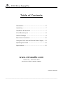
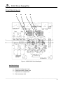
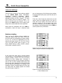
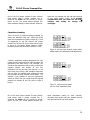
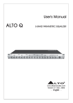
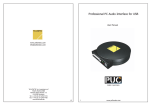
Owner’s Manual
MOON Series
310 LP
Phono Preamplifier
310LP Phono Preamplifier
Important Safety Instructions
1.
Read these instructions.
2.
Keep these instructions.
3.
Heed all warnings.
4.
Follow all instructions.
5.
Do not use this apparatus near water.
6.
Clean only with a dry cloth.
7.
Do not block ventilation openings. Install in accordance with the manufacturer’s instructions.
8.
Do not install near any heat sources such as radiators, heat registers, stoves or another apparatus that produces
heat.
9.
Do not defeat the safety purpose of the polarized or grounding type plug. A polarized plug has two blades with one
wider than the other. A grounding-type plug has two blades and a third grounding prong. The wide blade or the third
prong is provided for safety. If the provided plug does not fit into the outlet, consult an electrician for replacement of
the obsolete outlet.
10. Protect the power cord from being walked on or pinched, particularly at plugs, convenience receptacles, and the
point where they exit from the apparatus. Unplug mains cord during transportation.
11. Only use attachments and accessories specified by the manufacturer.
12.
Use only with the cart, stand, tripod, bracket, or table specified by the manufacturer or sold with the
apparatus. When a cart is used, use caution when moving the cart/apparatus combination to avoid injury
from tip over.
13. Unplug this apparatus during lightning storms or when unused for long periods of time.
14. Refer all servicing to qualified service personnel. Servicing is required when the apparatus has been damaged in any
way, such as when the power cord or plug has been damaged; liquid has been spilled or objects have fallen into the
apparatus; or the apparatus has been exposed to rain or moisture, does not operate normally, or has been dropped.
15. No naked flame sources, such as candles, should be placed on the apparatus.
WARNING: TO REDUCE THE RISK OF FIRE OR ELECTRIC SHOCK,
DO NOT EXPOSE THIS APPLIANCE TO RAIN OR MOISTURE.
____________________________________________________________________________________
310LP Phono Preamplifier
Important Safety Instructions
(cont’d)
The lightning flash with the arrowhead symbol, within an equilateral triangle, is
intended to alert the user to the presence of uninsulated “dangerous voltage” within
the product’s enclosure that may be of sufficient magnitude to constitute a risk of
electric shock to persons.
The exclamation point within an equilateral triangle is intended to alert the user to the
presence of important operating and maintenance (servicing) instructions in the
literature accompanying the appliance.
Marking by the “CE” symbol (shown left) indicates compliance of this device with the
EMC (Electromagnetic Compatibility) and LVD (Low Voltage Directive) standards of the
European Community
Please read all instructions and precautions carefully and completely before
operating your Simaudio MOON 310LP Phono Preamplifier.
1.
ALWAYS disconnect your entire system from the AC mains before connecting or disconnecting any cables,
or when cleaning any component. To completely disconnect this apparatus from the AC mains, disconnect
the power supply cord plug from the AC receptacle.
2.
The MOON 310LP must be terminated with a three-conductor AC mains power cord which includes an earth
ground connection. To prevent shock hazard, all three connections must ALWAYS be used. Connect the
MOON 310LP only to an AC source of the proper voltage; Both the shipping box and rear panel serial
number label will indicate the correct voltage. Use of any other voltage will likely damage the unit and void
the warranty
3.
AC extension cords are NOT recommended for use with this product. The mains plug of the power supply
cord shall remain readily accessible.
4.
NEVER use flammable or combustible chemicals for cleaning audio components.
5.
NEVER operate the MOON 310LP with any covers removed. There are no user-serviceable parts inside. An
open unit, especially if it is still connected to an AC source, presents a potentially lethal shock hazard. Refer
all questions to authorized service personnel only.
6.
NEVER wet the inside of the MOON 310LP with any liquid. If a liquid substance does enter your MOON
310LP, immediately disconnect it from the AC mains and take it to your MOON dealer for a complete checkup.
7.
NEVER spill or pour liquids directly onto the MOON 310LP.
8.
NEVER block air flow through ventilation slots or heatsinks.
9.
NEVER bypass any fuse.
10. NEVER replace any fuse with a value or type other than those specified
11. NEVER attempt to repair the MOON 310LP. If a problem occurs contact your MOON dealer.
12. NEVER expose the MOON 310LP to extremely high or low temperatures.
13. NEVER operate the MOON 310LP in an explosive atmosphere.
14. ALWAYS keep electrical equipment out of reach of children.
15. ALWAYS unplug sensitive electronic equipment during lightning storms.
16. WARNING: Do not expose batteries or battery pack to excessive heat such as sunshine, or fire or the like.
____________________________________________________________________________________
310LP Phono Preamplifier
Table of Contents
Introduction .................................................... 6
Unpacking ....................................................... 7
Installation & Placement ................................... 7
Circuit Board Layout ......................................... 8
Internal Settings .............................................. 9
Rear Panel Connections ....................................12
Using the 310LP with an External Power Supply ...13
Operating the 310LP ........................................14
Specifications .................................................15
www.simaudio.com
Simaudio Ltd., 1345 Newton Road
Boucherville, Quebec J4B 5H2 CANADA
Date Code: 20140717
____________________________________________________________________________________
310LP Phono Preamplifier
Introduction
Thank you for selecting the MOON 310LP Phono
Preamplifier as a part of your music/cinema
system. This component has been designed to offer
state-of-the-art high-end performance in an elegant
package, while retaining all the sonic hallmarks on
which Simaudio has made its reputation. We have
spared no effort to ensure that it is amongst the
finest phono preamplifiers available. We have been
building high-performance audio equipment for over
25 years, and the know-how gained through our
cumulative experience is an important reason why
MOON audio components are so musically
satisfying.
The performance of your 310LP will continue to
improve during the first 300 hours of listening. This
is the result of a “break-in” period required for the
numerous high quality electronic
throughout this phono preamplifier.
parts
used
Before setting up your new MOON 310LP, we
encourage you to please read this manual
thoroughly to properly acquaint yourself with its
features. We hope you enjoy listening to the
MOON 310LP Phono Preamplifier as much as
the pride we have taken in creating this fine audio
product. We understand the power and emotion of
music and build our products with the goal of
faithfully capturing these elusive qualities.
The information contained in this manual is subject
to change without notice. The most current version
of this manual is available on our official website at
http://www.simaudio.com
Your MOON 310LP Phono Preamplifier incorporates many significant design features to achieve its “world class”
level of performance. This is an abbreviated list of the more important features:
Isolated power supply on a separate circuit board using a
toroidal transformer with 2 stages of voltage regulation
An extremely short signal path for a faster transient
response
End-user adjustments for capacitance loading,
resistance loading and gain level to extract exceptional
performance from virtually all high quality phono
cartridges
Optional external power supply
Four-layer PCB tracings with dedicated ground and
power planes using pure copper for low impedance
characteristics. The advantages are better circuit layouts
resulting in much shorter signal paths and a vastly
improved signal-to-noise ratio
Rigid chassis construction to minimize the effects of
external vibrations
End-user adjustments to alternate between the RIAA
and IEC equalization curves
A symmetrical circuit design with accurate matching
of the very finest high quality electronic components
Single-ended RCA and Balanced XLR output connectors
Designed to be powered up at all times for optimal
performance
Power supply voltage regulation includes i2DCf
(Independent Inductive DC Filtering) derived from the
Evolution Series for increased dynamic range
Low operating temperature for an ultra-long life
expectancy.
____________________________________________________________________________________
6
310LP Phono Preamplifier
Unpacking
The MOON 310LP phono preamplifier should be removed from its box with care.
The following accessories should be included inside the box with your phono preamplifier:
9
9
9
9
AC power cable
5/64” Allen key to remove the chassis cover and make internal adjustments
This owner’s manual
Warranty and product registration information (USA and Canada only)
Once the MOON 310LP is unpacked, inspect it
thoroughly and report any damage to your dealer
immediately. We suggest that you keep all of the
original packaging, storing it in a safe, dry place in
case you’re required to transport this product. The
customized packaging is specially designed to
protect the 310LP from any potential damage
during transit.
Please write the serial number of your new MOON 310LP in the space provided below for future reference.
Serial No.: ________________
Installation & Placement
The MOON 310LP requires reasonable ventilation
to maintain an optimum and consistent operating
temperature. As a result, it should be placed in a
location with empty space around it for proper heat
dissipation. As well, it should be placed on a solid
level surface. You should avoid placing it near a heat
source or inside a closed cabinet that is not well
ventilated as this could compromise this
component’s performance and reliability. You should
never place another component directly on top of
this phono preamplifier.
The 310LP is more sensitive than most other types
of audio components to EMI (electro-magnetic
interference) from power supplies and motors.
Consequently, it should be placed at a minimum
distance of 18 inches from power supplies,
turntables, tape decks, AC line filters, etc.
____________________________________________________________________________________
7
310LP Phono Preamplifier
Circuit Board Layout
A
B
A
B
C
C
D
D
Figure 1: MOON 310LP Circuit Board layout
Available Settings:
A – Resistance loading jumper bank
B – Capacitance loading jumper bank
C – Equalization curve jumper bank
D – Gain level jumper bank
____________________________________________________________________________________
8
310LP Phono Preamplifier
Internal Settings
There are four (4) types of input settings available
on the MOON 310LP Phono Preamplifier;
Capacitance
loading,
Resistance
loading,
Equalization curve and Gain level. Each setting is
adjustable through the use of jumpers. For each
type of setting, there are 2 banks of jumpers – one
each for the left and right channels. This is the
result of the 310LP’s genuine mirror-image circuit
design which yields exceptional stereo separation.
Always place the preamplifier that your 310LP is
connected to, either into mute or stand-by mode
prior to changing any of the following input settings.
Then disconnect the AC power cord from the rear of
the 310LP.
There are a total of eight (8) screws that you must
remove using the included allen-key four each on
either side of the chassis. Once these screws are
removed, carefully lift off the chassis cover. Once
the cover is removed, you are ready to make all of
the necessary internal adjustments to the 310LP to
achieve optimal sonic performance.
Resistance Loading:
There are five (5) different settings available for
setting the resistive load; 10Ω, 100Ω, 470Ω, 1kΩ
and 47kΩ which are represented by jumper sockets
J9, J10, J11, J12 and J13 respectively for the left
channel and jumper sockets J27, J28, J29, J30 and
J31 for the right channel (refer to figure 2). The
factory default setting is 47kΩ, therefore jumpers
will be found in sockets J13 & J31.
Figure 2: Left and right channel jumper banks
default setting for resistance load adjustments
In the event that you’re using a moving magnet
(MM) cartridge, it is recommended that you leave the
jumpers inserted in sockets J13 & J31 (the factory
default) for a 47kΩ resistive load. Conversely, if
you’re using a moving coil (MC) cartridge, experiment
with the four (4) other available loads ranging from
10Ω through 1KΩ, selecting the load that provides
the best possible sound quality. For example, if you
decided on using the resistance setting of 100Ω, then
you would insert the supplied jumpers into sockets
J10 and J28 (refer to figure 3) .
Figure 3: Left and right channels set to
a 100Ω resistance load
____________________________________________________________________________________
9
310LP Phono Preamplifier
One of the five jumper sockets for each channel
must always have a jumper inserted into it,
otherwise the 310LP will not produce an output
signal. As well, you should always maintain the
same resistance setting for both channels, otherwise
sound will vary between the left and right channels
of your audio system. Finally, it is strongly
recommended that you never use the 47kΩ
resistive load setting for moving coil
cartridges.
Capacitance Loading:
There are three (3) different settings available for
setting the capacitive load; 0pF, 100pF and 470pF
which are represented by jumper sockets J6, J7 and
J8 respectively for the left channel and jumper
sockets J24, J25 and J26 for the right channel (refer
to figure 4). The factory default setting is 100pF,
therefore jumpers will be found in sockets J7 & J25.
Figure 4: Left and right channel jumper banks
default setting for capacitance load adjustments
Typically, capacitance loading adjustments will only
impact the sonic performance of a MM cartridge. We
recommend that when using a MC cartridge, you
should set the capacitance load to 0pF by placing the
supplied jumpers into sockets J6 and J24,
respectively for the left and right channels. In the
event that you’re using a MM cartridge experiment
with the three (3) available loads, selecting the load
that provides the best possible sound quality. For
example, if you decided on using the capacitance
setting of 470pF, then you would insert the supplied
jumpers into sockets J8 and J26 (refer to figure 5
below).
Figure 5: Left and right channels
set to a 470pF capacitance load
One of the three jumper sockets for each channel
must always have a jumper inserted into it,
otherwise the 310LP will not produce an output
signal. As well, you should always maintain the
same capacitance setting for both channels,
otherwise sound quality may vary between the left
and right channels of your audio system.
____________________________________________________________________________________
10
310LP Phono Preamplifier
Equalization Curve:
The MOON 310LP Phono Preamplifier is equipped
with circuitry for two (2) different equalization
curves; The RIAA standard and the less common IEC
modified curve. The main difference is that the RIAA
curve produces a flat frequency response from 20Hz
to 20kHz; The IEC curve acts as a subsonic filter
removing inaudible infrasonic bass below 20Hz.
Figure 6: RIAA Equalization curve jumper setting
Jumper sockets J5 and J21, for the left and right
channels respectively, are used to set the 310LP’s
equalization curve. These jumpers sockets have three
pins allowing for 2 different possible positions. The
factory default position is for the RIAA curve as
shown in figure 6 where the jumper connects the
lower 2 pins. To select the IEC curve, place the
jumper over the upper 2 pins as shown in figure 7.
Figure 7: IEC Equalization curve jumper setting
To determine which curve you should use, do as
follows: with the 310LP set to the RIAA curve,
watch the movement of your loudspeaker’s bass
drivers – if their motion doesn’t follow the pattern of
the record currently playing and/or you see
excessive driver movement, chances are you should
use the IEC curve to eliminate the subsonic
information not present on the record.
Gain Setting:
There are four (4) gain settings available on the
MOON 310LP. They are 40dB for MM cartridges
and 54dB, 60dB and 66dB for MC cartridges.
However, keep in mind that when using the
balanced XLR outputs, each of these gain levels
increase by a factor of 6dB to 46dB, 60dB, 66dB and
72dB respectively (note: to keep the circuit board
labelling simple, only the single-ended RCA gain
levels are indicated).
There are three (3) jumpers sockets for each channel
that are used to adjust the gain level setting; J16,
J17 and J18 for the left channel; J32, J33 and J34 for
the right channel. Each of these jumpers sockets
have three pins allowing for 2 different possible
positions. As well, there is a detailed diagram printed
on the circuit board, located just below and to the
right of each of these jumper banks, that shows the
jumper positioning for the four available gain settings
(see figure 8).
Figure 8: Left and right channel jumper
banks for gain level settings
____________________________________________________________________________________
11
310LP Phono Preamplifier
The factory default gain setting is 40dB, whereby all
three jumpers in each bank are mounted to the left.
In the event that you are using a MC cartridge, you
will need to change the gain setting to either 54dB,
60dB or 66dB. The basic rule to determine gain for
a MC cartridge is as follows: For a low output MC
cartridge (0.7mV and lower), set the gain level to
66dB; for a medium output MC (0.7mV to 1.5mV)
set the gain level to 60dB; for a high output MC (>
1.5mV) set the gain level to 54dB. However, as is
the case with the other internal settings, let your
ears be best judge as to what the best sounding
gain setting should be. When using a MM cartridge,
never set the gain above 40dB, otherwise you will
overload the 310LP’s circuit, resulting in a very
distorted output signal.
To select a gain level of 60dB, you would mount the
jumpers for sockets J16, J17, J32 and J33 to the
right, and the jumpers for sockets J18 and J34 to the
left as shown in figure 9.
Once you’ve completed all necessary adjustments,
carefully place the chassis cover back into place,
making sure that the eight screw holes line up with
their respective sockets on the main chassis, and
replace the screws using the included allen-key.
Figure 9: Left & right channels set to 60dB gain
Rear Panel Connections
Figure 10: MOON 310LP Rear panel
The rear panel will look similar to Figure 10. There is
one pair of single-ended inputs on RCA connectors
located in the center with a ground post directly
below. Connect the cables from your turntable to
these inputs and the ground lead wire to the ground
post. The MOON 310LP Phono Preamplifier has
two pairs of outputs; One single-ended pair on RCA
connectors and one balanced pair on XLR
connectors.
If the preamplifier or integrated amplifier you’re
connecting the 310LP to has balanced inputs, its
highly advantageous to use the 310LP’s XLR
outputs. This will provide you with an even better
signal-to-noise ratio and increased gain by a factor
of 6dB. Don’t hesitate to use high quality
interconnects. Poor quality cables can degrade the
overall sonic performance of your system.
Finally on the right side the IEC receptacle, labeled
“AC Power” for the included AC power cord. Directly
above the IEC receptacle is a 4-pin XLR connector
labeled “DC Power”; this is for the optional 310LP
external power supply upgrade.
____________________________________________________________________________________
12
310LP Phono Preamplifier
Using the 310LP with an External Power Supply
The MOON 310LP Phono Preamplifier can be
operated with the optional MOON 320S Power
Supply (purchased separately). Referring to figure
11 below, you will see an array of four (4) jumper
sockets labeled STR1, STR2, STR3 and STR4. The
factory default position for the 2 jumpers is in
sockets STR2 and STR4 (positions B in figure 11).
A
B
A
To properly use the MOON 310LP in conjunction
with the MOON 320S, you will need to move these
2 jumpers into sockets STR1 and STR3 (positions A
in figure 11). For further details, please refer to your
MOON 320S owner’s manual. Failure to make
these adjustments may cause damage that is
not covered by warranty.
B
Figure 11: MOON 310LP Circuit Board layout
If you are using either the MOON P-8 Controller,
MOON 850P Controller as power supply, or the
MOON 820S Power Supply, these 2 jumpers
must remain in sockets STR2 and STR4 (positions B
in figure 11). You should NOT move these jumpers
from their factory default position.
____________________________________________________________________________________
13
310LP Phono Preamplifier
Operating the 310LP
We recommend that you leave your MOON 310LP
Phono Preamplifier powered up at all times to
maintain optimal performance. If you plan to be
away from your home for a few days, powering off
the Phono Preamplifier may not be a bad idea.
Once fully “broken-in”, please keep in mind that
your 310LP will require several hours of playing
time before it reaches its peak performance after
you’ve powered it up again.
Turning on your MOON 310LP for the first time
Since this Phono Preamplifier is not equipped
with
an
on/off
power
switch,
when
connecting/disconnecting the AC power cord you
are actually turning the unit on/off. Prior to
making the AC connection for the first time,
make sure that every cable is properly
connected to avoid any problems. Once the
310LP is connected to an AC source, the blue
LED on the unit’s front panel will illuminate,
indicating that the 310LP is now powered up
and ready for use.
On and Off Sequence
To avoid having any annoying noises (ie. “thumps”
and “pops”) emanate from your speakers when
powering your 310LP on or off, you should always
power up your 310LP phono preamplifier before
powering up your preamplifier or integrated
amplifier. As well, always power down your 310LP
after powering down your preamplifier or integrated
amplifier.
____________________________________________________________________________________
14
310LP Phono Preamplifier
Specifications
Circuit Layout ................................................
Power Supply Transformer ..............................
Power Supply Capacitance .............................
Single-ended inputs ........................................
Input Impedance - Adjustable ........................
Input Capacitance - Adjustable .......................
Single-ended output ......................................
Balanced output ............................................
Gain – Adjustable (for single-ended outputs) ..
Gain – Adjustable (for balanced outputs).........
Input overload @ 40dB gain ............................
Input overload @ 54dB gain ............................
Input overload @ 60dB gain ............................
Input overload @ 66dB gain ............................
Signal-to-noise Ratio (full scale @ 40dB gain) ..
Signal-to-noise Ratio (full scale @ 40dB gain) ..
Signal-to-noise Ratio (full scale @ 66dB gain) ..
Signal-to-noise Ratio (full scale @ 66dB gain) ..
Maximum Output (1kHz @ 10KΩ)....................
Frequency Response – RIAA & IEC Curve .........
IEC Curve Effect..............................................
Crosstalk @ 1kHz ..........................................
Intermodulation Distortion .............................
THD (20Hz - 20kHz) .....................................
Power Consumption ........................................
AC Power Requirements .................................
Shipping Weight ............................................
Dimensions (W x H x D, inches) .....................
Mirror-image symmetrical circuit
10VA
14,000µF
1 pair (RCA)
47, 100, 470, 1k, and 47kΩ
0, 100, and 470 pF
1 pair (RCA)
1 pair (XLR)
40, 54, 60 and 66dB
46, 60, 66 and 72dB
58mV RMS
11mV RMS
6mV RMS
3mV RMS
110dBr
114dBr with 320S Power Supply
88dBr
92dBr with 320S Power Supply
6.0 Volts
20Hz - 20kHz (± 0.5dB)
-7dB @ 10Hz
-100dB
< 0.009%
< 0.001%
6 Watts
120V or 240V, 60Hz or 50Hz
7 lbs / 3 Kgs
8 x 3.25 x 11
Balanced Input Pin Assignment:
Pin 1 ........................... Ground
Pin 2 ........................... Positive
Pin 3 .......................... Negative
Fuse Replacement:
For the 120V version use a 0.1A slow blow (5 x 20mm size).
For the 230V version use a 0.1A slow blow (5 x 20mm size).
____________________________________________________________________________________
15