1
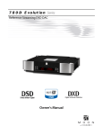
810LP Evolution Series
Reference Dual-Mono Phono Preamplifier
Owner’s Manual
810LP Evolution Series
Owner’s Manual
Important Safety Instructions
1.
Read these instructions.
2.
Keep these instructions.
3.
Heed all warnings.
4.
Follow all instructions.
5.
Do not use this apparatus near water.
6.
Clean only with a dry cloth.
7.
Do not block ventilation openings. Install in
accordance with the manufacturer’s instructions.
8.
Do not install near any heat sources such as
radiators, heat registers, stoves or another
apparatus that produces heat.
9.
Do not defeat the safety purpose of the polarized or
grounding type plug. A polarized plug has two
blades with one wider than the other. A groundingtype plug has two blades and a third grounding
prong. The wide blade or the third prong is
provided for safety. If the provided plug does not fit
into the outlet, consult an electrician for
replacement of the obsolete outlet.
10. Protect the power cord from being walked on or
pinched, particularly at plugs, convenience
receptacles, and the point where they exit from the
apparatus.
Unplug
mains
cord
during
transportation.
11. Only use attachments and accessories specified by
the manufacturer.
12. Use only with the cart, stand, tripod, bracket, or
table specified by the manufacturer
or sold with the apparatus. When a
cart is used, use caution when
moving the cart/apparatus combination to avoid
injury from tip over.
13. Unplug this apparatus during lightning storms or
when unused for long periods of time.
14. Refer all servicing to qualified service personnel.
Servicing is required when the apparatus has been
damaged in any way, such as when the power cord
or plug has been damaged; liquid has been spilled
or objects have fallen into the apparatus; or the
apparatus has been exposed to rain or moisture,
does not operate normally, or has been dropped.
15. No naked flame sources, such as candles, should be
placed on the apparatus.
WARNING:
TO REDUCE THE RISK OF FIRE OR ELECTRIC SHOCK, DO NOT
EXPOSE THIS APPLIANCE TO RAIN OR MOISTURE.
810LP Evolution Series
Important Safety Instructions
(cont’d)
The lightning flash with the arrowhead symbol, within an equilateral triangle, is
intended to alert the user to the presence of uninsulated “dangerous voltage” within
the product’s enclosure that may be of sufficient magnitude to constitute a risk of
electric shock to persons.
The exclamation point within an equilateral triangle is intended to alert the user to the
presence of important operating and maintenance (servicing) instructions in the
literature accompanying the appliance.
Marking by the “CE” symbol (shown left) indicates compliance of this device with the
EMC (Electromagnetic Compatibility) and LVD (Low Voltage Directive) standards of the
European Community
Please read all instructions and precautions carefully and completely
before operating your MOON 810LP Phono Preamplifier.
1.
ALWAYS disconnect your entire system from
the AC mains before connecting or
disconnecting any cables, or when cleaning any
component. To completely disconnect this
apparatus from the AC mains, disconnect the
power supply cord plug from the AC receptacle.
2.
6.
NEVER wet the inside of the MOON 810LP with
any liquid. If a liquid substance does enter your
MOON 810LP, immediately disconnect it from
the AC mains and take it to your MOON dealer
for a complete check-up.
The MOON 810LP must be terminated with a
three-conductor AC mains power cord which
includes an earth ground connection. To
prevent shock hazard, all three connections
must ALWAYS be used. Connect the MOON
810LP only to an AC source of the proper
voltage; Both the shipping box and rear panel
serial number label will indicate the correct
voltage. Use of any other voltage will likely
damage the unit and void the warranty
7.
NEVER spill or pour liquids directly onto the
MOON 810LP.
8.
NEVER block air flow through ventilation slots
or heatsinks.
9.
NEVER bypass any fuse.
AC extension cords are NOT recommended for
use with this product. The mains plug of the
power supply cord
shall remain readily
accessible.
12. NEVER expose the MOON 810LP to extremely
high or low temperatures.
13. NEVER operate the MOON 810LP in an
explosive atmosphere.
4.
NEVER use flammable or combustible
chemicals for cleaning audio components.
14. ALWAYS keep electrical equipment out of
reach of children.
5.
NEVER operate the MOON 810LP with any
covers removed. There are no user-serviceable
parts inside. An open unit, especially if it is still
connected to an AC source, presents a
potentially lethal shock hazard. Refer all
questions to authorized service personnel only.
15. ALWAYS
unplug
sensitive
electronic
equipment during lightning storms.
3.
10. NEVER replace any fuse with a value or type
other than those specified
11. NEVER attempt to repair the MOON 810LP. If a
problem occurs contact your MOON dealer.
16. WARNING: Do not expose batteries or battery
pack to excessive heat such as sunshine, or fire
or the like.
Owner’s Manual
Table of Contents
Introduction
Unpacking
Installation & Placement
Bottom Panel Layout s
Cartridge Loading Adjustments
Rear Panel Connections
Balanced Operation
Operating the 810LP
Remote Operation
Specifications
6
7
7
8
9
11
12
12
13
14
www.simaudio.com
Simaudio Ltd., 1345 Newton Road
Boucherville, Québec J4B 5H2 CANADA
Date Code: 20150805
810LP Evolution Series
Introduction
Thank you for selecting the MOON 810LP Dual-Mono
Phono Preamplifier as a part of your music/cinema
system. This component has been designed to offer
state-of-the-art high-end performance in an elegant
package, while retaining all the sonic hallmarks on
which Simaudio has made its reputation. We have
spared no effort to ensure that it is amongst the finest
phono preamplifiers available. We have been building
high-performance audio equipment for over 30 years,
and the know-how gained through our cumulative
experience is an important reason why MOON audio
components are so musically satisfying.
The performance of your 810LP will continue to
improve during the first 500 hours of listening. This is
the result of a “break-in” period required for the
numerous high quality electronic parts used
throughout this phono preamplifier.
Before setting up your new MOON 810LP, we
encourage you to please read this manual thoroughly to
properly acquaint yourself with its features. We hope
you enjoy listening to the MOON 810LP Phono
Preamplifier as much as the pride we have taken in
creating this fine audio product. We understand the
power and emotion of music and build our products
with the goal of faithfully capturing these elusive
qualities.
The information contained in this manual is subject to
change without notice. The most current version of this
manual is available on our official website at
http://www.simaudio.com
Your MOON 810LP Phono Preamplifier incorporates
many significant design features to achieve its “world
class” level of performance. This is an abbreviated list of
the more important features:
artifacts. Power supply featuring a "pi-type" filter using
40,000uF of capacitance and dual choke inductance (2x
200mH). The result is a power supply with a noise floor of 150dB related to 1.0V, DC - 100kHz.
4 stages of our newly developed M-LoVo MOON low voltage
DC regulation circuit; a highly sophisticated circuit made up
of a clever combination of IC’s and discrete parts that is
virtually free of noise, yielding an exceptionally fast, precise,
and stable DC voltage. The result is a power supply with a
noise floor of -150dB related to 1.0V, DC - 100kHz.
Power supply voltage regulation includes i2DCf (Independent
Inductive DC Filtering); 1 inductor for each and every chip (i.e.
OpAmp, etc.) in the audio circuit’s signal path – 24 stages in
all.
The dedicated audio circuit board is mounted on a 5-point
gel-based floating suspension, derived from our M-Octave
technology, originally developed for the reference MOON
850P Preamplifier.
Adjustable impedance loading - 64 available settings from
12.1Ω to 47kΩ
Adjustable capacitance loading - 16 available settings from
0pF to 1120pF
Adjustable gain settings - 16 available settings from 40dB to
70dB
Selectable equalization curves for both the RIAA and the
IEC standards
Customized parts include metallized polypropylene film
capacitors with very tight tolerances of 1%
Four-layer PCB tracings with dedicated ground and power
planes using pure copper for low impedance characteristics.
The advantages include better circuit layouts resulting in a
much shorter signal path and a vastly improved signal-tonoise ratio
Optional external power supply.
Ultra rigid chassis construction to minimize the effects of
external vibrations.
The oversized power supply, located within the main chassis,
is housed in an isolated enclosure that is constructed from
satin coated 14-gauge steel to eliminate all traces of AC
6
The shortest possible signal path for a faster transient
response and the lowest possible noise floor.
Owner’s Manual
Unpacking
The MOON 810LP should be removed from its box with care.
The following accessories should be included inside the box with your phono preamplifier:
9
9
9
9
AC power cable
One (1) pen shaped plastic hand tool for making DIP-switch adjustments
This owner’s manual
Warranty and product registration information
(USA and Canada only)
Once the 810LP is unpacked, inspect it thoroughly and report any damage to your dealer immediately. We
suggest that you keep all of the original packaging, storing it in a safe, dry place in case you’re required to
transport this product. The customized packaging is specially designed to protect the 810LP from any potential
damage during transit.
Please write the serial number of your new MOON 810LP in the space provided below for future reference.
Serial Number
Installation
The 810LP is more sensitive than most other types of
audio components to EMI (electro-magnetic
interference) from power supplies and motors.
Consequently, it should be placed at a minimum
distance of 18 inches from power supplies, turntables,
tape decks, AC line filters, etc. You should never place
another component directly on top of this phono
preamplifier. It should be placed on a solid, level surface.
You should avoid placing it near a heat source or inside
a closed cabinet that is not well ventilated as this could
compromise the preamplifier’s performance and
reliability.
If the surface you have chosen isn’t perfectly level, each
of the four (4) cones of your 810LP are height
adjustable; carefully using your fingers, you can either
raise each leg by turning the cone underneath
clockwise, or lower each leg by turning it
counterclockwise.
We strongly recommend that you leave these cones
mounted to the component at all times for reasons
related to both performance and aesthetics.
7
810LP Evolution Series
Bottom Panel Layout
Figure 1: MOON 810LP Bottom Panel layout
Settings for cartridge resisitance loading, cartridge
capaciitance loading, gain and equalization curve are all
done using white colored DIP switches located on the
810LP’s bottom panel as shown above in figure 1. There
are two (2) banks of DIP switches – The upper bank
provides for the capacitance and resistance loading
adjustments; the lower bank for gain level and
8
equalization curve settings. Examples of the DIP switch
positions for all available settings are clearly shown on
the bottom panel – below and to the right of the actual
DIP switches. Since the MOON 810LP is a genuine dualmono design, there are 2 sets of DIP switches for each
adjustment – one each for the left and right channels.
Owner’s Manual
Cartridge Loading Adjustments
to the right position (‘OFF’) as seen in the example to
the right.
Prior to making any of these adjustments, always
disconnect the AC power cord and all interconnects
from MOON 810LP. We strongly recommend using the
pen shaped plastic hand tool that we have included with
your 810LP as it was specifically designed for this
purpose. Using another tool made from a material other
than plastic may damage the DIP switches and/or
scratch the painted surface on the bottom of the
810LP’. Finally, to achieve the best possible sonic
performance, it is absolutely necessary that all settings
be identical for both the left and the right channels.
A comprehensive diagram of the DIP switch
combinations for all 16 available capacitance loading
settings can be seen on the bottom panel, immediately
to the right of the switches. Finally, the values written
beside the DIP switch number represent the
capacitance load if only that switch is in the left position
(‘ON’). For example, when only switch 10 is in the left
position (‘ON’), the load value will be 470pF; when only
switch 9 is in the left position (‘ON’), the load value will
be 330pF; and finally when only switch 8 is in the left
position (‘ON’), the load value will be 220pF.
In the following examples, the color white
always indicates the position - left (‘ON’)
or right (‘OFF’) of the DIP switch. In the
example to the left, the DIP switch is in the
left position (‘ON’). This is to be consistent with the
actual white color of these switches.
Capacitance Loading:
Resistance Loading:
There are sixty-four (64) unique resistance loading
settings available using DIP switches 1 through 6,
located at the bottom of the upper DIP switch bank. The
range of available settings starts at 12.1Ω and ends at
47kΩ:
There are sixteen (16) unique capacitance loading
settings available using DIP switches 7 through 10,
located at the top of the upper DIP switch bank. The
range of available settings begins at 0pF and ends at
1120pF:
Figure 3: Left and right channel DIP switches for
resistance loading adjustments
Figure 2: Left and right channel DIP switches for
capacitance loading adjustments
The factory default is 100 pF, whereby DIP
switches 10, 9, and 8 are all in the right (‘OFF’)
position and DIP switch 7 is in the left position
(‘ON’) as seen in the example to the right. This
setting would be applicable for most moving
magnet cartridges.
When you are using a moving coil cartridge,
you will most likely want to set the
capacitance loading to 0pF. This is done by
positioning all four DIP switches (7, 8, 9, & 10)
The factory default is 47KΩ, whereby DIP
switches 6, 5, 4, 3, 2 and 1 are all in the right
(‘OFF’) position as seen in the example to the
right. This setting would be applicable for
most moving magnet cartridges.
When you are using a moving coil cartridge,
you will most likely want to set the resistance
loading to a much lower impedance value.
For
instance,
when
your
cartridge
manufacturer recommends a value of 100Ω,
you would position DIP switch 3 to the left
(‘ON’) and the other remaining switches (1, 2, 4, 5 & 6) to
the right position (‘OFF’) as seen in the example to the
right. We strongly recommended that you never use the
47kΩ resistive load setting for moving coil cartridges.
____________________________________________________________________________________
9
810LP Evolution Series
A comprehensive diagram of the DIP switch
combinations for all 64 available resistance loading
settings can be seen on the bottom panel, immediately
to the right of the switches and just below the
previously mentioned capacitance settings diagram.
Finally, the values written beside the DIP switch number
represent the resistance load if only that switch is in the
left position (‘ON’). For example, when only switch 1 is in
the left position (‘ON’), the load value will be 22Ω; when
only switch 4 is in the left position (‘ON’), the load value
will be 221Ω; and finally when only switch 6 is in the left
position (‘ON’), the load value will be 1000Ω.
Note: Choosing a loading impedance for a moving coil
cartridge is not an exact science as there are many
variables that can affect the manufacturer’s recommended
setting. Choosing the best impedance is ultimately a
compromise between what sounds best to your own ears
and what works best for the cartridge, based on its internal
workings. When experimenting with different impedance
settings, always keep in mind that a poorly loaded moving
coil cartridge will result in sonic performance yielding a
lack of definition, reduced bass performance, as well as
aggressive upper-mid and high frequencies.
Gain Setting:
The example to the right shows a gain level
setting of 60.0dB where DIP switches 5 and 3
are in the left (‘ON’) position and DIP switches
2 and 4 are in the right (‘OFF’) position.
When you are using a moving coil cartridge, you will
need to increase the gain level setting. This is a general
rule for determining the gain of a MC cartridge: For a
low output MC cartridge (0.7mV and lower), set the gain
level to at least 66dB; for a medium output MC (0.7mV
to 1.5mV) set the gain level to 60dB; for a high output
MC (> 1.5mV) set the gain level to 54dB. Since every
audio system is different, these are just approximated
values.
Equalization Curve:
The MOON 810LP Phono Preamplifier is equipped
with circuitry for two (2) different equalization curves;
The RIAA standard and the less common IEC modified
curve. The main difference is that the RIAA curve
produces a flat frequency response from 20Hz to 20kHz;
The IEC curve acts as a subsonic filter removing
inaudible infrasonic bass only below 20Hz. Using DIP
switch 1 on lower bank. The factory default is the RIAA
curve whereby DIP switch 1 is in the right (‘OFF’)
position. To change to the IEC curve, simply move this
DIP switch to the left (‘ON’) position.
There are sixteen (16) unique gain level settings
available using DIP switches 2 through 5, located at the
top of the lower DIP switch bank. The range of available
settings runs from 40dB all the way up to 70.0dB:
Figure 5: Left and right channel DIP switches for
equalization curves
Figure 4: Left and right channel DIP switches for gain
level settings
The factory default gain level setting is 40dB
whereby DIP switches 5, 4, 3 & 2 are set to the
right position (’OFF’). This setting would be
applicable for most moving magnet
cartridges.
10
To determine which curve is best for you, perform this
simple test: Use the 810LP with the RIAA curve and
watch the movement of your loudspeaker’s bass drivers.
If their motion doesn’t follow the pattern of the record
you’re playing or you see excessive driver movement,
chances are you should use the IEC curve to eliminate
the subsonic information not present on the record.
Owner’s Manual
Rear Panel Connections
Figure 6: Rear panel of MOON 810LP
The rear panel will look similar to Figure 6 (above). All audio connectors are located on the left side of the rear
panel. As a result of the MOON 810LP Phono Preamplifier’s balanced and symmetrical circuit design, the layout
of these audio connectors follows the same orientation: A pair of single-ended RCA input connectors are located
in the middle and on either side you will find the balanced XLR input connector for that same channel. Connect
the cables from your turntable to either the RCA or XLR inputs. The design of the 810LP allows for ONLY 1 input
connection so you cannot use both types of input connectors. Immediately to each side of the XLR input connectors
are the balanced XLR output connectors. Beside each XLR output is the single-ended RCA output connector for
that same channel. You can use either or both the XLR outputs and RCA outputs to connect to your
preamplifier/integrated amplifier. If the preamplifier/integrated amplifier you’re connecting the 810LP to has
balanced inputs, its highly advantageous to use the 810LP’s XLR outputs. This will provide you with an even
better signal-to-noise ratio.
When you’re using the balanced XLR inputs, you must
first remove the factory installed “dummy” XLR
jumpers (see figure 7 below) from the back panel XLR
connectors and store them in a safe place. These
jumpers are required ONLY when using the singleended RCA inputs. In If you decide to switch to singleended input mode, you must reinstall the XLR jumper
(between pins 1 and 3) exactly as show below. The
purpose of these jumpers is to help maintain the lowest
possible noise level when not using the 810LP’s
balanced input circuitry.
To the right of the array of audio connectors is a 4-pin
XLR connector labeled “DC Input” which is reserved for
use with the 820S external power supply. Directly to
the right of the 4-pin XLR are two 12 Volt triggers, each
on a 1/8” mini-jack; one input and one output, the latter
for use in if you wish you to “daisy chain” an additional
component on the same trigger circuit. Finally on the
far right side is the “AC Power” section with a main
power switch (“0”=off, “1”=on) and IEC receptacle for
the included AC power cord.
Figure 7: XLR connector without and with jumper
accessory
____________________________________________________________________________________
11
810LP Evolution Series
The MOON 810LP is equipped with a 5-point version of
our M-Octave Damping system, whereby the main
audio circuit board is coupled to the chassis using an 5point floating suspension that is designed to eliminate
distortion caused by the “Microphonic effect” of
airborne vibrations. All audio connectors are directly
mounted to this main audio circuit board. As a result, a
dual-layered rear panel is required to accommodate this
suspension, with the outer layer affixed to the 810LP’s
chassis and the inner layer – with the audio connectors
– affixed to the main audio circuit board. Consequently,
when you connect cables to (or disconnect cables from)
the 810LP, this inner rear panel will move slightly – This is
normal. These rear panel layers are completely
independent of each other, only coming into physical
contact when either connecting or disconnecting
cables.
Balanced Operation
When using an unbalanced interconnect, the audio
signal runs through both the center wire and the
shield/ground wire. Any noise picked up by this
interconnect (ie. nearby magnetic fields such as an AC
power cord) will be reproduced by the integrated
amplifier, then heard through the loudspeakers.
Conversely, a balanced interconnect has three separate
conductors; one for the ground and two for the actual
signal. These two signals are identical except that one is
180 degrees out of phase with the other. For example,
when one conductor is carrying a signal of +2 Volts, the
other will be carrying a signal of –2 Volts. When these
two inverted signals on a balanced line are output from
the MOON 810LP, any noise picked up by the
interconnect will be eliminated since a differential
circuit amplifies only the difference between these two
signals: Noise on a balanced interconnect will be equal
on both conductors and therefore cancel out.
12
Operating the 810LP
We recommend that you leave your MOON 810LP dualmono phono preamplifier powered up at all times to
maintain optimal performance. When you plan to be
away from your home for a few days, powering off the
preamplifier may not be a bad idea. Once fully “brokenin”, please keep in mind that your 810LP will require
several hours of playing time before it reaches its peak
performance after you’ve powered it up again.
Turning on your MOON 810LP for the first time
Prior to turning the phono preamplifier on for the first
time, make sure that every cable is properly connected
to avoid any problems. Flick the main rocker switch,
located on the rear panel, labeled “POWER” to the ‘1’
(on) position to place your 740P in to standby mode.
Next, briefly press the push button labeled “Standby”
located on the front panel. You will hear a very faint
click sound confirming that everything is in order. The
blue LED on the front panel will illuminate, indicating
that the 810LP is now powered up and ready for use.
On and Off Sequence
To avoid having any annoying noises (ie. “thumps” and
“pops”) emanate from your speakers when powering
your 810LP on or off, you should always power up your
810LP phono preamplifier before powering up your
preamplifier or integrated amplifier. As well, always
power down your 810LP after powering down your
preamplifier or integrated amplifier.
Owner’s Manual
Remote Operation
Figure 8: Remote Operation with 12V Trigger
In figure 8 we have a 810LP Phono Preamplifier, 850P Preamplifier, and 870A Power Amplifier connected
together via their respective 12V triggers; The two 12V trigger outputs on the 850P are connected to the 12V
trigger inputs on both the 810LP (using a 1/8” mini-jack cable) and 870A. When you turn on the 850P via remote
control (or its Standby button), both the 810LP and 870A will turn on automatically. The same rule applies when
you put the 850P into Standby mode.
____________________________________________________________________________________
13
810LP Evolution Series
Specifications
Configuration
Fully balanced differential, dual-mono
Inputs: Balanced / Single-ended
1 pair (XLR) / 1 pair (RCA)
Input Impedance – Adjustable
64 settings from 12.1Ω to 47kΩ
Input Capacitance – Adjustable
16 settings from 0pF to 1120pF
Gain Level – Adjustable
16 settings from 40dB to 70dB
Outputs: Balanced / Single-ended
1 pair (XLR) / 1 pair (RCA)
Input overload @ 40dB gain
200mV RMS (XLR) / 100mV RMS (RCA)
Input overload @ 55.5dB gain
30mV RMS (XLR) / 15mV RMS (RCA)
Input overload @ 60dB gain
20mV RMS (XLR) / 10mV RMS (RCA)
Input overload @ 65dB gain
10mV RMS (XLR) / 5mV RMS (RCA)
Input overload @ 70dB gain
5mV RMS (XLR) / 2.5mV RMS (RCA)
Signal-to-noise Ratio (full scale @40dB gain)
115dBr
Signal-to-noise Ratio (full scale @55.5dB gain)
108dBr
Signal-to-noise Ratio (full scale @60dB gain)
105dBr
Signal-to-noise Ratio (full scale @65dB gain)
100dBr
Signal-to-noise Ratio (full scale @70dB gain)
95dBr
Frequency Response – RIAA & IEC Curve
20Hz - 20kHz (± 0.1dB)
Output Impedance
50Ω
IEC Curve Effect
-7dB @ 10Hz
Crosstalk @ 1kHz
106dB
Intermodulation Distortion
0.001%
THD (20Hz - 20kHz)
0.0008%
Power Consumption @ idle
10 Watts
AC Power Requirements
120V / 60Hz or 240V / 50Hz
Shipping Weight
40 lb. / 18 Kg.
Dimensions (W x H x D, inches / cm.)
18.75 x 4.0 x 16.8 / 47.6 x 10.2 x42.7
Balanced Input Pin Assignment:
Pin 1
Pin 2
Pin 3
Fuse Replacement:
Ground
Positive
Negative
For the 120V version use a 0.2A slow blow (5 x 20mm size).
For the 230V version use a 0.1A slow blow (5 x 20mm size)
14