1
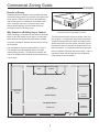
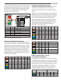
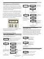
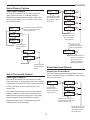
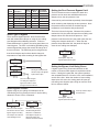
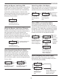
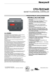
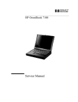
Commercial Zoning Guide
eWD3 Zoning Panel
eWD3 Zoning Panel
ZONE THERMOSTATS
3
2
HVAC
PANEL
ZONE DAMPERS
1
3
2
eWD3X Expansion Panel
1
Quick View
Quick View
The commercial zoning solutions use the
eWD3P Zoning Panel, eWD3X
Expansion Panel and our rugged
CRDA250 dampers. These products
provide a cost effective solution for 3 to
12-zone installations for multi-stage
gas/electric, conventional heat pumps
and dual fuel heat pumps.
eControls
PDM Programming/D splay Module
eControls
Model eWD3
MENU
The CRDA250 dampers use a powerful,
24VAC modulating actuator that provides
efficient airflow and can eliminate
constructing bypass duct work.
NEXT
CANCEL SAVE
eWD3X Expansion Panel
ZONE THERMOSTATS
3
2
ZONE DAMPERS
1
3
2
1
UP / YES
DOWN / NO
The panels’s PDM tutors the installer
through the selection of thermostat,
equipment and damper options as well as
advanced options for controlling staging
by demand, bypass control and
numerous other options.
The contractor can enter their name and
telephone number for display by the user.
Multiple installations can be cloned to
save time and insure consistent option
selection.
Introduction to Zoning
2
Set the Number of Zones Used
14
Select Heat/Cool Priority
20
Understanding Comfort
2
Select the Type of Damper
15
Select Dampers Open in Cont Fan
20
Defining Zones
3
Select the Type of Thermostats
15
Select Timing Options
20
Placing the Zone Dampers
4
Select Advanced Options
15
Enter Contractor Info
21
eWD3P Zoning Panel Features
5
15
Display Data and Selections
21
eWD3P Zoning Panel Illustration
6
Select Control Mode- Zones,
CFM or Percent Demand
Display Error Messages
21
Wiring 24VAC Power
7
Select Control Mode Using CFM
16
Display Equipment Status
21
Determining Transformer VA
7
Select Control Mode Using Zones
16
Display Sensor Readings
21
Commercial Damper
8
Select Control Mode Using %Demand
16
Display Zone Thermostat Status
22
Damper Wiring
8
Select Type of Bypass
17
Display Zone Damper Status
22
Compatible Zone Thermostats
9
Select Bypass Control
17
Display Equipment Selections
22
Zone Thermostat Wiring, Heat/Cool
9
Select Bypass Limit Using Pressure
17
Display Zone Thermostat Selections
22
Zone Thermostat Wiring, Heat Pump
10
Select Bypass Limit Using Zones
17
Display Zone Damper Selections
22
Emergency Heat Control
10
Select Bypass Limit Using CFM
18
Display Zone Data
22
Vacant Terminal Wiring
10
Select Bypass Limit Using %Demand
18
Display Bypass Selections
22
Outdoor Temperature Sensor
11
Select Opposite Service
18
Display Advanced Option Selections
22
Discharge Temperature Sensor
11
Select Purge after a Call
18
Start Installation Test
23
Duct Pressure Sensor
12
Select DSBK Low Speed Fan
18
Start Damper Test
23
HVAC Equipment Wiring
12
Select Emergency Heat Control
18
Start Cooling Test
23
Staging in Gas/Electric Systems
13
Select Automatic Em Heat
19
Start Heating Test
23
Staging in Heat Pump Systems
13
Select Em Heat Memory
19
Start Emergency Heating Test
24
DSBK Low Speed Fan Terminal
13
Selecti Staging Options
19
Start Airflow/Bypass Test
24
Using the Installer Options Menu
14
Select Staging by Demand
19
Restore Factory Defaults
24
14
Select Automatic Timed Upstaging
19
Air Balancing
24
14
Select Moderate Weather Staging
20
Select Equipment Options
Set the High and Low
Discharge Temperature Limits
Commercial Zoning Guide
eControls
Benefits of Zoning
Dividing a facility into separate zones provides the same
comfort and energy efficiency as if each zone had its own
HVAC system. Each zone has its own thermostat that
controls the amount of conditioned air provided to that
zone. And when zones are not used or set to more
energy efficient settings, the thermostat reduces or
terminates the airflow to those zones.
Figure 1. Manufacturing facility with offices in the front and
manufacturing and warehousing in the back.
Why Spaces in a Building Vary in Comfort
When a building is commissioned, the airflow is balanced
based on the CFM needs of each space. Unfortunately
these demands vary dynamically with season, weather,
occupancy, orientation, windows and the comfort level of
the occupants.
The perimeter and interior zones are shown in the floor
plan in figure 2. The perimeter zones have the greatest
variation in demand due to the effect of weather on the
window areas and to a lessor extent, the walls. Figure 3
illustrates the effect of windows on the heat load for the
perimeter spaces. It is important to define the perimeter
areas as different zones than the interior space. And it is
important to break the perimeter spaces into different
zones based on their orientation.
This is illustrated using the example shown in Figure 1.
The example is the administration offices of a small
manufacturing company. The offices are located in the
front of the building and manufacturing and warehousing
is in the back.
MANUFACTURING & WAREHOUSE
MEN
WOMEN
CONFERENCE
ROOM
PURCHASING
ENGINEERING
DRAFTING
STAFF
GENERAL
ADMINISTRATIVE
Interior Zones
QUALITY
CONTROL
Peripheral Zones
MARKETING
Figure 2. Floor plan of manufacturing facility.
2
GENERAL
MANAGER
eControls
Defining the Zones
Figure 3 shows the effect of solar and transmitted heat
loads are significantly greater in perimeter zones than
internal zones. And the effect of these loads changing
dynamically with weather, orientation and time of day will
have a significant effect on comfort. Zoning solves this
problem.
PEOPLE 5%
Figure 4 shows how the offices in the example might be
divided into zones. The perimeter areas and the internal
areas are divided into different zones. The perimeter
areas have been further divided into different zones. The
conference room is a separate zone because it is only
used intermittently. Other offices have been divided into
different zones to provide more personal comfort.
PEOPLE 10%
LIGHTING
25%
Check for Comfort Problems
Discuss the discomfort problems being experienced by
the staff. Here are some problems to look for.
LIGHTING
45%
TRANSMISSION
25%
If an area is too warm during the cooling season and
too cold during the heating season, it may indicate the
ducts servicing the area are not large enough.
TRANSMISSION
15%
SOLAR
45%
Sensible
Heat Load
Perimeter
Zone
If most areas are too warm during peak cooling season
or too cold during peak heating season, it may indicate
the heating or cooling equipment is not large enough.
SOLAR
30%
If areas are too warm during heating calls or too cold
during cooling calls, zoning will improve this problem.
Sensible
Heat Load
Internal
Zone
Figure 3. Sensible heat load for perimeter and internal zones.
MANUFACTURING & WAREHOUSE
MEN
WOMEN
Zone1
CONFERENCE
ROOM
12 People
Zone5
Zone6
ENGINEERING
DRAFTING
STAFF
8 People
GENERAL
ADMINISTRATIVE
30 People
PURCHASING
Zone2
2 People
QUALITY
CONTROL
Zone4
GENERAL
ADMINISTRATIVE
10 People
Figure 4. Zoning plan for manufacturing facility.
3
Zone3
GENERAL
MANAGER
2 People
eControls
Defining the Zones
Figure 4 shows how the offices in the example might be
divided into zones. Figure 5 shows the air distribution.
The perimeter areas consist of Zones 1 through 5 and the
internal area is Zone6. The demand for each of these
zones can be calculated using ACCA Manual N. Shown
in Table 1 is the peak cooling CFM demand calculated by
Carrier for the example building.
Zone# Description
Although many zoning panels assume equal sized zones
when operating the HVAC equipment, our panels allow
the contractor to enter the CFM or %Demand for each
zone for intelligent staging of the equipment. This will be
explained further when the zoning panel options are
described.
Placing the Zone Dampers
Calculated Area CFM Per
CFM
Sq. Ft. Sq. Ft.
1
Conference Room
681
375
1.82
2
QC/Purchasing
317
225
1.41
3
General Manager
509
300
1.70
4
Marketing
1461
1050
1.39
5
Engineering
1540
900
1.71
6
General Administration
2043
3150
.65
The dampers are placed in the duct work to control the
airflow to each zone. Some zones may require two or
more dampers to control the airflow because of the duct
work layout. Zones 5 and 6 in the example shown in
Figure 6 require two dampers. The CRDA250 dampers
are commercial quality and can be operated open/close or
modulating.
Table 1. Zone CFM requirements.
Modulating dampers can be used to eliminate
constructing bypass duct work with a barometric damper.
The non-calling zone dampers can be used to bypass
excess airflow. The zoning panel calculates the amount
of bypass required based on the demand and opens the
non-calling zone dampers just enough to maintain the
minimum airflow. This method of bypass is preferred by
the CEC rather than bypass excess airflow to the return
duct.
A calculation of CFM requirements using ACCA Manual N
is the most accurate method of determining CFM
requirements. From Table 1, the average CFM per
square foot for perimeter zones is 1.58 whereas interior
zones require only .65 CFM per square foot. And the size
of the zones vary greatly.
MANUFACTURING & WAREHOUSE
MEN
Zone1
WOMEN
18
10
24
18
24
20
16
20
CONFERENCE
R O
12 eople
Zon 5
ENGINEERING
D FT NG
STAFF
8 Peo le
20
20
PURCHASING
10
Zone6
10
GENERAL
ADMINISTRATIVE
30 People
16
10
10
Zone2
2 Peop
QUALI
CONTROL
16
16
MARKETING
10 People
16
16
18
Zone4
Figure 5. Duct work layout.
4
16
Zone3
GENE L
MANAGER
2 People
eControls
MANUFACTURING & WAREHOUSE
Zone1
WOMEN
18
Damper
Zone5
Damper
Zone6
20
20
Zone6
Zone5
Tstat
Damper
Zone1
Damper
Zone6
20
16
Damper
Zone2
Tstat
Zone2
Zone5
Tstat
Zone6
Tstat
Zone1
MEN
Zone2
Damper
Zone5
Damper
Zone4
24
Tstat
Zone4
Damper
Zone3
16
Zone3
Tstat
Zone3
16
Zone4
Figure 6. Damper and thermostat placement.
eWD3 Zoning Panel
The eWD3P Zoning Panel is shown in figure 7. This
panel uses the PDM on the panel to select and program a
wide range of options, display the status of each zone
thermostat, the equipment, dampers and the sensors. It
can also perform installation tests to insure the installation
is operating properly and can even display the
contractor’s name and telephone number.
Zones
Up to 3 zones on the eWD3P and up
to 12 zones using the eWD3X
expansion panels.
Compatible
Equipment
Gas/Electric systems, conventional
and dual fuel Heat Pumps.
Gas/Electric Stages
Up to three-stage heating and twostage cooling.
Heat Pump Stages
Up to four-stage heating ( two
compressors and auxiliary heat) and
two-stage cooling.
Compatible Zone
Thermostats
Any combination of heat/cool or heat
pump thermostats. 24VAC or battery
powered or power robbing.
Compatible Zone
Dampers
Any 24VAC open/close damper or
eControls commercial, modulating
CRDA250 series.
5
Bypass Control
External using a bypass duct with a
barometric damper or by
automatically modulating the noncalling zone dampers.
Optional Sensors
Discharge and outdoor temperature
sensors and duct pressure sensor.
LED Display
Multi-color LEDs indicate the call
status of each zone thermostat,
equipment call status, panel status
and status of each damper.
Viewable with the cover installed or
removed.
PDM Display
The PDM display is a 2 line by 16
character display that tutors the
installer through the selection of
options or the display of information.
The user can display information and
even the contractor info.
eControls
Multi colored LED indicates when panel is operating normally
(blinking green), an option, timer or temperature sensor is
inhibiting calls or staging (blinking yellow) or when a sensor
failure has occurred (blinking red). The PDM can be used
to display the equipment status and any error messages.
Multi colored LED indicates when the HVAC system
is in heating (red), cooling (yellow) or continuous
fan (green). LED blinks red or yellow when staged
and blinks green when in purge cycle.
Multi colored LEDs indicate when a zone
thermostat is calling for heating (red),
cooling (yellow) or continuous fan (green).
LEDs blink when staged.
LEDs indicate when damper is fully open
(green), fully closed (off) or when damper is
in a modulated position (blinking green).
Wiring access, top
and bottom
TSTAT3 TSTAT2 TSTAT1
Relay
PDM Programming/Display Module
eControls
Model eWD3P
Relay
Relay
Relay
NEXT
CANCEL SAVE
UP / YES
DOWN / NO
Optional output to control
modulating equipment.
Relay
Relay
Screwless terminals.
Relay
TSTAT3
OPN
CLS
COM
OPN
CLS
COM
OPN
CLS
COM
COM
COM
24V
Relay
C
R
W1
W2
Y1
Y2
G
Relay
Relay
SENSORS
DAS
DAS
OAS
OAS
+5V
PRS
GND
Terminals for gas/electric
or heat pump equipment.
DS/BK Terminals for low
speed fan control.
Relay
C
R
W1
W2
Y1
Y2
G
RH RC jumper. Cut for split
system with separate heating
and cooling transformers.
Relay
DMPR1
MENU
RC
RH
O
W1/B
W2/E
W3/E
Y1
Y2
G
DS/BK
HVAC SYSTEM
RH-RC JMPR
Relay
DMPR1
TSTAT2
Terminals for optional supply
air temperature and outdoor
temperature sensors.
DMPR3 DMPR2 DMPR1
DMPR2
TSTAT1
Terminals for gas/electric or
heat pump type thermostats.
24VAC, power robbing or
battery operated.
C
R
W1/E
W2
Y1
Y2
G
VAC
PANEL
24VAC
Model eWD3P
Use an external switch or
timer to connect 24VAC
to the VAC terminal to
select Vacant mode.
eControls
PDM used to configure
panel, display features
and performance and
test panel and equipment.
HVAC
Terminal for 24VAC power
open/close, spring return or
modulating damper actuator.
Large wiring channel.
Wiring access.
Terminals for 24VAC
power for the panel, zone
thermostats and damper
actuators.
EXTERNAL PDM
Optional duct pressure
sensor for bypass control
using modulating, non
calling zone dampers.
Automatic reset fuse.
EXPANSION
Connector for eWD3X
expansion panel.
Connector for PDM carried
by the installer.
Quick View
Figure 7. eWD3P Zoning Panel features.
eWD3P Zoning Panel
ZONE THERMOSTATS
3
2
HVAC
PANEL
ZONE DAMPERS
1
3
2
1
PDM Programming/Display Module
eControls
Model eWD3P
MENU
NEXT
CANCEL SAVE
PCB43755C
UP / YES
DOWN / NO
Figure 8. eWD3P Zoning Panel
with cover installed.
6
eControls
Power Wiring
24VAC
COM
COM
24VAC
24VAC
Line
Max VA
Total VA
eWD3 Panel
10VA
10VA
eWD3X Expansion
10VA
Zone Thermostats 6 @1.8VA
Zone Dampers
Figure 8. 24VAC power wiring for panel and dampers.
eWD3 Panel
Maximum VA
Typical VA
10VA
10VA
24VA
[email protected]
36VA
60VA or 40VA/40VA
Zone Dampers
[email protected]
48VA
75VA or 40VA/40VA
Zone Dampers
[email protected]
60VA
80VA or 40VA/4oVA
Table 4. Transformer required for a 6-zone installation.
10VA
10VA
1.8VA
1.0VA
eWD3 Panel
0.7VA
eWD3X Expansion 2@10VA
Table 2 shows the transformer VA required for a 3-zone
installation with 3 to 12 dampers to construct the zones.
In zoning operation at least one zone is not operating
when the other zones are operating and thermostats only
use the 1.8VA power when they are calling for heating,
cooling or fan. This combined with the 6.25-second
operating time for a damper reduces the real VA required.
The transformer VA ratings shown in the Tables 4, 5 and 6
conservatively reflect the real VA required.
Total VA
10VA
10VA
Transformer VA
20VA
Zone Thermostats
[email protected]
16.2VA
Zone Dampers
[email protected]
36VA
Zone Dampers
[email protected]
48VA
50VA/40VA
Zone Dampers
[email protected]
60VA
50VA/50VA
Zone Dampers
[email protected]
72VA
80VA/40VA
80VA or 40VA/40VA
Table 5. Transformer required for a 9-zone installation.
eWD3P Panel
Max VA
Total VA
10VA
10VA
eWD3X Expansion 3@10VA
Transformer VA
20VA
Zone Thermostats [email protected] 21.6VA
[email protected]
48VA
50VA/50VA
10VA
Zone Dampers
[email protected]
48VA
60VA/60VA
Zone Dampers
[email protected]
60VA
60VA/60VA
Zone Dampers
[email protected]
72VA
80VA/60VA
Total VA
10 VA
Transformer VA
3 @1.8VA
5.4VA
Zone Dampers
[email protected]
12VA
40VA
Zone Dampers
[email protected]
24VA
40VA
Zone Dampers
[email protected]
36VA
50VA
Zone Dampers
[email protected]
48VA
60VA
Table 6. Transformer required for a 12-zone installation.
Table 3. Transformer required for a 3-zone installation.
When an eWD3P Zoning Panel is used with one or more
eWD3X Expansion Panels, a single transformer can be
used to power the eWD3P and the eWD3X. When one
transformer is used it is important that the wiring of the
24VAC and COM terminals be consistent as shown in
Figure 9.
eWD3 Zoning Panel
24VAC
Max VA
Zone Dampers
Max VA
Zone Thermostats
COM
COM
24VAC
50VA or 40VA/40VA
[email protected]
Zone Thermostat
eWD3P Panel
10VA
10.8VA
Zone Dampers
eWD3XExpansion
Zone Damper
4.0VA
Table 2. VA rating for zoning components.
Transformer VA
24VAC
Line
eWD3X Exp nsion
24VAC
COM
COM
24VAC
Figure 9. One transformer powering eWD3P and eWD3X.
7
eControls
Zone Damper Wiring
The CRDA250 damper series are heavy duty dampers for
commercial applications. They use the A250 modulating,
24VAC actuator for positioning a damper up to 24 inches
in diameter with 2-inch H2O pressure.
The three terminals on the zone damper actuator are
wired to the corresponding zone damper terminals on the
zoning panel.
OPEN
COM OPN CLS
Made in USA
L
RF
AI
eContro s
OW
Damper Actuator
Open/Close/Modulating
24VAC, 4VA
Model A250-MOC
24VAC, 4VA Actuator with
250 in-oz of torque with
precise modulation.
CLOSE
CRDA250 Zone Dampers
Zoning Panel
Thermostat Wire
3 conductor, 18 AWG
Z1DPR
COM
CLS
OPN
Zone 1 Damper
Zoning Panel
COM
24 gage spiral wrap
shell.
Damper
COM
Terminal Function
24VAC common
OPN
OPN
Opens damper
CLS
CLS
Closes Damper
Figure 10. Wiring CRDA250 actuator.
Two 26 gage blades with foam gasket
sandwiched between blades for maximum
airflow efficiency when open and less than
1.25% leakage at 1.0 in-H2O when closed.
When 2 or more dampers are used for a zone, the
dampers can be wired in parallel. Up to 6 dampers can
be wired in parallel to form a zone.
Figure 9. CRDA250 Series damper.
Open/close or modulating.
Air Leakage
Shell Length
CRDA250-006
CRDA250-008
CRDA250-009
CRDA250-010
CRDA250-012
CRDA250-014
CRDA250-016
CRDA250-018
CRDA250-020
CRDA250-022
CRDA250-024
6 inches
8 inches
9 inches
10 inches
12 inches
14 inches
16 inches
18 inches
20 inches
22 inches
24 inches
10 inches
10 inches
10 inches
12 inches
14 inches
16 inches
18 inches
20 inches
22 inches
24 inches
26 inches
Table 7. Damper Model number, diameter and length.
CLOSE
OPEN
CLOSE
OPEN
Zoning Panel Damper1 Damper6 Terminal Function
COM
24VAC common
COM
COM
Maximum Static 2 inches H2O.
Pressure
Diameter
Z5DPR
COM
CLS
OPN
Zone 5 Damper
Less than 1.25% air leakage within the
damper when closed and less than .25%
external air leakage.
Model No.
Thermostat Wire
3 conductor, 18 AWG
COM OPN CLS
Dual V-grooved, 26 gage, galvanized steel
with neoprene gasket sandwiched
between blades for efficient airflow..
Damper Actuator
Open/Close/Modulating
24VAC, 4VA
Damper Blade
Model A250-MOC
Spiral wrapped, 22 to 26 gage galv steel.
Zoning Panel
Zone 5 Damper
Electrical Power 24VAC, 4VA operating and .7VA holding.
Damper Shell
COM OPN CLS
Made in USA
eContro s
Red LED on when fully closed and green
LED On when fully open.
Made in USA
LED Indicators
eContro s
Control
24VAC applied to Open or Close terminal.
Damper Actuator
Open/Close/Modulating
24VAC, 4VA
Output Torque
6.25 seconds from fully open to fully
closed.
250 inch-ounces.
Operation Time
Model A250-MOC
Operation
OPN
OPN
OPN
Opens damper
CLS
CLS
CLS
Closes Damper
Figure 11. Wiring CRDA250 actuators when multiple dampers
are used to form a zone.
8
eControls
Placing the Zone Thermostats
Zone Thermostat Wiring,
Gas/Electric Equipment
A thermostat is installed in each zone. It should be
located on an interior wall and out of sunlight so it sensors
the zone temperature. Figure 6 illustrates the location of
the thermostats in the example. Each zone thermostat is
wired to the corresponding terminals on the zoning panel.
Zone thermostats used with gas/electric equipment are
either single or two-stage Heat/Cool thermostats and
thermostat terminals are wired to corresponding terminals
on the zoning panel.
Figure 7 shows the connections for a single-stage
Heat/Cool, battery powered or power sharing thermostat
and Figure 12 shows a 24VAC powered Heat/Cool
thermostat.
Compatible Zone Thermostats
Any 24VAC, battery powered or power robbing thermostat
can be used with the eWD3 Zoning Panel. The type of
thermostat (Heat/Cool or Heat Pump) can be selected for
each zone.
Zone Thermostat
1 Stage Heat/Cool
Battery or Power Sharing
When the panel controls a conventional or dual fuel heat
pump, a heat pump thermostat should be used in Zone1
to have access to select emergency heating. The other
zones can use Heat/Cool thermostats. The Zone1 Heat
Pump thermostat is the master control emergency
heating. Zoning panels used with Gas/Electric systems
should use Heat/Cool thermostats. Some examples of
compatible thermostats are shown below.
Zoning Panel
R
W1/O/B
Y
G
Z1TSTAT
C
R
W1/OB
W2/E
Y1
Y2
G
VAC
Thermostat Zoning Panel Terminal Function
Venstar T5800
R
R
Provides 24VAC to other terminals
W1/O/B
W1/OB
Activates heating when 24VAC
Y1
Y1
Activates cooling when 24VAC
G
G
Activates fan when 24VAC
Figure 12. Wiring 1-stage, Heat/Cool, battery powered or
power robbing zone thermostat.
Zone Thermostat
1 Stage Heat/Cool
24VAC Powered
Venstar T1700
Zoning Panel
C
R
W1/O/B
Y
G
Venstar T2300FS
Z1TSTAT
C
R
W1/OB
W2/E
Y1
Y2
G
VAC
Thermostat Zoning Panel Terminal Function
R
R
24VAC for Thermostat and Terminals
C
C
24VAC Common
W1/O/B
W1/OB
Activates heating when 24VAC
Y1
Y1
Activates cooling when 24VAC
G
G
Activates fan when 24VAC
Figure 13. Wiring 1-stage, Heat/Cool, 24VAC zone thermostat.
9
eControls
Two-stage thermostats can be used when 2-stage
equipment is controlled by the zoning panel. The use of
2-stage thermostats or call demand to control equipment
staging is discussed when options are selected.
Zone Thermostat
2 Stage Heat/Cool
24VAC Powered
Zoning Panel
C
R
W1/O/B
W2
Y1
Y2
G
Z1TSTAT
C
R
W1/OB
W2/E
Y1
Y2
G
VAC
Thermostat Zoning Panel Terminal Function
R
R
24VAC for Thermostat and Terminals
C
C
24VAC Common
W1/O/B
W1/OB
Activates Stage1 Heating when 24VAC
W2
W2/E1
Activates Stage2 Heating when 24VAC
Y1
Y1
Activates Stage1 Cooling when 24VAC
Y2
Y2
Activates Stage2 Cooling when 24VAC
G
G
Activates Fan when 24VAC
Figure 14. Wiring 2-stage, Heat/Cool, 24VAC zone thermostat
Zone Thermostat Wiring,
Heat Pump Equipment
Zone thermostats used with heat pump equipment have
either single or two-stage compressor outputs, an O or B
output for selecting heating or cooling and an output for
controlling auxiliary electric strip heating or fossil fuel
heating in a dual fuel heat pump.
Figure 15 shows the connections for a 2-stage Heat/Cool,
24VAC heat pump thermostat and the function of each
terminal.
Emergency Heat Control
Although a Heat/Cool thermostat could be used in Zone1,
a Heat Pump is required for emergency heat control.
When Zone1 makes a call for emergency heating, the
zoning panel will activate emergency heating when
making a heating call.
The W/E terminal acts as a call for auxiliary heating or
emergency heating. In emergency heating the Y1 and Y2
terminals will be 0VAC.
When using Heat/Cool thermostats with zoning panels
controlling a heat pump, they are wired the same as with
a gas/electric system as shown in Figure 14.
Vacant Terminal at Zone1
The VAC terminal can be used with a switch or timer to
activate the VAC terminal and initiate the Vacant operation.
In the Vacant mode the equipment and all the zone
dampers are controlled by the Zone1 thermostat. The
Zone1 thermostat can be a 7-day programmable and can
be set to energy saving temperatures for periods when the
building is not occupied. This allows manual thermostats
to be used in all other zones and they will be automatically
over-ridden when the VAC terminal is activated.
Vacant Operation Using a Switch
Figure 16 shows a switch being used to activate the
Vacant mode, Program the Zone1 thermostat for energy
saving nighttime temperatures. Set the Vacant/Occupied
switch to Vacant and all the zones will use the Zone1
temperature settings.
Model SW01
Wall Switch
OCCUPIED
Zone Thermostat
1 Stage Heat/Cool
Battery or Power Sharing
Zoning Panel
C
R
W1/O/B
Y1
Y2
W2
G
Z1TSTAT
C
R
W1/OB
W2/E
Y1
Y2
G
VAC
VACANT
R
24VAC for Thermostat and Terminals
C
C
24VAC Common
W1/O/B
W1/OB
Controls the reversing valve.
W2
W2/E1
Activates Auxiliary Heating when 24VAC
Y1
Y1
Activates Stage1 Compressor when 24VAC
Y2
Y2
Activates Stage2 Compressor when 24VAC
G
G
Activates Fan when 24VAC
Figure 15. Wiring 1-stage, Heat/Cool, battery powered or
power sharing zone thermostat.
Z1TSTAT
C
R
W1/OB
W2/E
Y1
Y2
G
VAC
Figure 16. Wall switch used to control Vacant mode.
Figure 17 shows a timer with dry relay contacts controlling
Vacant mode.
Thermostat Zoning Panel Terminal Function
R
Zoning Panel
24-Hour or 7-Day Timer
Figure 17. Timer used to control Vacant mode.
10
Zoning Panel
Z1TSTAT
C
R
W1/OB
W2/E
Y1
Y2
G
VAC
eControls
Optional Outdoor Temperature Sensor
Optional Discharge Air Temperature Sensor
A Model TS03 outdoor temperature sensor is required for
dual fuel heat pump control. It is used to switch the heat
pump from compressor heating to fossil fuel heating. The
changeover temperature is set using the PDM.
A Model TS02 temperature sensor can be used to monitor
the discharge air temperature to insure it does not exceed
high and low temperature limits set using the PDM. The
sensor is automatically detected by the panel. If an open
or short occurs in the sensor or wiring, the Panel Status
LED will blink red.
An outdoor temperature sensor can also be used to limit
the use of secondary heating in moderate weather.
If either the heating or cooling discharge air temperature
exceeds the limits set on the panel, the heating or cooling
will downstage until the temperature is within limits. The
fan is kept running.
The zoning panel automatically detects if an outdoor
temperature sensor is installed. If an open or short
occurs in the sensor or wiring, the panel detects it and will
blink the Panel Status LED red until it is corrected.
6 inch Stainless
Steel Tube
SENSORS
SENSORS
Model TS03
Temperature Sensor
DAS
DAS
OAS
OAS
+5V
PRS
GND
Thermistor Temperature Sensor
Model TS02
Temperature Sensor
Figure 18. Outdoor temperature sensor connection.
DAS
DAS
OAS
OAS
+5V
PRS
GND
Figure 20. Discharge Air temperature sensor connection.
To Panel
Thermistor
Sensor
Stainless Steel
Tube
Screw attaches
cover to base.
Rubber Gasket
Rubber Gasket
Base
Base
Cover
Connect to
Sensor Terminals
on Panel
Figure 21. Discharge Air temperature sensor wiring.
Screw attaches cover
to base.
Figure 19. Outdoor temperature sensor wiring.
Installing the Outdoor Temperature Sensor
Find a suitable location that is not in direct sunlight and
protected from rain or snow such as under the eves. Drill
a 3/8 inch access hole and pass the thermostat cable
through the drilled hole, gasket and the access hole in the
base of the sensor. Use the wire nuts supplied to connect
the sensor wires to the thermostat cable wires. Either
sensor wire can be connected to the red or white
thermostat wire. Secure the sensor base using the two
screws and attach the sensor cover to the base as shown
in figure 19.
Installing the Discharge Temperature Sensor
The Discharge Air temperature sensor should be installed
in the supply duct or plenum at least 12 inches from any
coils or heating elements. Drill a 3/8 inch access hole and
pass the stainless steel tube through the gasket and the
hole. Secure the sensor base with the two screws.
Connect the sensor wires to the thermostat cable using
the wire nuts. Replace the sensor cover with the
thermostat cable passing through the wire retainer.
Warning!
Be careful when drilling into the plenum not to damage
any coils or heating elements in the plenum.
11
eControls
Optional Duct Pressure Sensor
HVAC Equipment Wiring
A Model PS01 pressure sensor can be used to monitor
the pressure in the ducts to control bypass using the noncalling zone dampers. If the pressure rises above the
pressure limit set, the non-calling zone dampers open just
enough to keep the pressure from exceeding the limit.
The zoning panel can control gas/electric, conventional
heat pumps and dual fuel heat pumps. The function of
the equipment control terminals on the zoning panel are
shown in Table 7.
Zoning Panel
SENSORS
Zoning Panel
+5V
PRS
GND
O
W1/B
W2/E
W3/E
Y1
Y2
G
DS/BK
DAS
DAS
OAS
OAS
+5V
PRS
GND
Terminal Function
+5V for Sensor Circuit
Pressure Signal
Ground for Sensor Circuit
Figure 22. Duct Pressure sensor connection.
Installing the Duct Pressure Sensor
Gas Electric Equipment Wiring
Wiring for a typical gas/electric system with two-stage
heating and two-stage cooling is shown in Figure 24.
+5V
PRS
GND
RC
RH
O
W1/B
W2/E
W3/E
Y1
Y2
G
DSBK
Screw terminals. Attach
to corresponding
terminals on the panel.
Mounting screws (furnished).
O reversing valve control
B reversing valve control
Stage1 auxiliary heating
Stage2 auxiliary heating
Stage1 Compressor
Stage2 Compressor
Indoor Fan Control
Low Speed Fan Control
Table 7. Equipment control terminal functions.
The Duct Pressure sensor pickup should be installed in
the main duct run about 6-feet before it splits into duct
runs to service specific zones. Drill a 3/8 inch diameter
hole and thread the sensor into the hole. Seal the sensor
and duct. Remove the sensor cover and attach the
sensor to the duct using the two screws. Attach the wires
as shown in figure 23. Replace the cover.
Screw attaches cover
to the base.
Not used
Stage1 Heating
Stage2 Heating
Stage3 Heating
Stage1 Compressor
Stage2 Compressor
Indoor Fan Control
Low Speed Fan Control
R
HVAC SYSTEM
Pressure Pickup
Sensor
+5V
PRS
GND
Gas/Electric System
Heat Pump
Terminal
RC
24VAC from cooling equipment
24VAC from heat pump
RH
24VAC from heating equipment
24VAC from heat pump
RC and RH are jumpered on the zoning panel.
Cut jumper for separate heating and cooling 24VAC
24VAC
W1
Gas Valve1
W2
Gas Valve2
Y1
Compressor1
Y2
Compressor2
G
Indoor Fan
Line
Zoning Panel Equipment Terminal Function
R
24VAC for Thermostat and Terminals
R
W1/B
Gas Valve, Stage1
W1
W2/E
Gas Valve, Stage2
W2
Y1
Compressor Stage1
Y1
Y2
Y1
Compressor Stage2
G
G
Indoor Fan
Figure 24. Wiring a Gas/Electric system with 2 heating
and 2 cooling stages.
Heat Pump Equipment Wiring
1/8IPS pressure connector.
Drill 3/8 inch diameter hole.
Pressure tubing (furnished).
Wiring for a typical heat pump system with two
compressors or a 2-stage compressor and 2 stages of
auxiliary heating is shown in figure 25.
Figure 23. Duct Pressure installation.
12
eControls
The O and the W1/B terminals are the O and B terminals
controlling the heat pump reversing valve. The W2/E and
W3/E terminals control the auxiliary heating electric strip
heating in a conventional heat pump or the fossil fuel
heating in a dual fuel heat pump.
R
HVAC SYSTEM
RC
RH
O
W1/B
W2/E
W3/E
Y1
Y2
G
DSBK
24VAC
O
O Rev Valve
W1
Aux Heat1
W2
Aux Heat2
Y1
Compressor1
Y2
Compressor2
G
Indoor Fan
Line
Staging in Heat Pump Equipment
In a heat pump configuration, the W1/B terminal is the B
reversing valve terminal, W2/E is the first stage of
auxiliary heat and W3/E is the second stage of auxiliary
heating.
Tables 9 and 10 show the panel outputs during staging of
heating and cooling for a Heat Pump system. The O and
B reversing valve terminals do not change state between
calls. They only change state when switch between
heating and cooling. Dual fuel heat pump do not downstage from fossil fuel heating to compressor heating to
prevent damage from over heating the indoor coil. The
panel will stay in fossil fuel heating until the call is
terminated. LS is the last state.
Zoning Panel Equipment Terminal Function
24VAC
R
R
O Reversing Valve
O
O
Auxiliary Heat, Stage1
W2/E
W1
Auxiliary Heat, Stage2
W3/E
W2
Stage1 Compressor
Y1
Y1
Stage2 Compressor
Y2
Y2
Indoor Fan
G
G
Terminal
Figure 25. Wiring a Heat Pump system with a 2-stage
compressor and 2 auxiliary heating stages.
No Call
Heat1
Heat2
Heat3
Heat4
EmHt1 EmHt1
OVAC
O
LS
0VAC
0VAC
0VAC
0VAC
W1/B
LS
24VAC 24VAC
24VAC
24VAC 24VAC 24VAC
W2/E
0VAC
0VAC
0VAC
24VAC
24VAC 24VAC
W3/E
0VAC
0VAC
0VAC
0VAC
24VAC 24VAC 24VAC
Y1
0VAC
24VAC 24VAC
24VAC
24VAC
0VAC
0VAC
Y2
0VAC
0VAC
24VAC
24VAC
24VAC
0VAC
0VAC
G
0VAC
24VAC 24VAC
24VAC
24VAC 24VAC 24VAC
0VAC
0VAC
Table 9. Output terminal states in heating calls in a Heat Pump.
Staging in Gas/Electric Equipment
Terminal
No Call
Fan
Cool1
Cool2
The zoning panel reads the heating and cooling demand
from each zone thermostat. The panel initiates, upstages,
down-stages or terminates a heating, cooling or fan call.
Table 8 shows the panel outputs during staging of heating
and cooling for a Gas/Electric system. If the Electric Fan
option is selected, the G terminal will be On (24VAC)
during heating calls. If the Gas Fan option is selected, the
equipment plenum sensor controls the fan in heating and
the G terminal is Off (0VAC).
Table 10. Terminal states in fan and cooling calls in a Heat Pump.
Terminal
DSBK Terminal Used to Control
Low Speed Fan Operation
No Call
Fan
Heat1
Heat2
NU
NU
Heat3
Cool1
Cool2
O
NU
NU
NU
NU
NU
W1/B
0VAC
0VAC
24VAC 24VAC
24VAC
0VAC
0VAC
W2/E
0VAC
0VAC
0VAC
24VAC
24VAC
0VAC
0VAC
W3/E
0VAC
0VAC
0VAC
0VAC
24VAC
0VAC
0VAC
Y1
0VAC
0VAC
0VAC
0VAC
0VAC
24VAC 24VAC
Y2
0VAC
0VAC
0VAC
0VAC
0VAC
0VAC 24VAC
G
0VAC
24VAC
0VAC
0VAC
0VAC
24VAC 24VAC
Table 8. Output terminal states in a Gas/Electric system.
O
LS
LS
24VAC
24VAC
W1/B
LS
LS
0VAC
0VAC
W2/E
0VAC
0VAC
0VAC
0VAC
W3/E
0VAC
0VAC
0VAC
0VAC
Y1
0VAC
0VAC
24VAC
24VAC
Y2
0VAC
0VAC
0VAC
24VAC
G
0VAC
24VAC 24VAC
24VAC
If the equipment has controls for low speed fan operation,
the DSBK terminal can be used. Low speed fan operation
is used during de-humidification using cooling and when a
limited number of zones are calling for heating or cooling.
The PDM can select whether DSBK is On or OFF to
control low speed fan operation. Table 11 shows the G
and DSBK terminals for both the On and Off option.
Fan Option
ON for Low Speed Fan
OFF for Low Speed Fan
Fan Speed
OFF
LOW
HIGH
OFF
LOW
HIGH
G
0VAC
24VAC
24VAC
0VAC
24VAC
24VAC
DSBK
0VAC
24VAC
0VAC
24VAC
0VAC
24VAC
Table 11. DSBK terminal states for high and low speed fan operation.
13
eControls
PDM Programming and Display Module
The PDM provides the installer with a tutorial method of
Selecting Equipment options, Selecting Damper options,
Selecting Tstat options, Selecting Advanced options, Enter
and Display Contractor info, Display Data and Selections
and Testing a zoning installation.
The installer menu is accessed by pressing and holding
the Menu key fo 7 seconds. The acceptable key strokes
are shown in the lower right corner of the LCD display.
The Cancel key can be used almost anytime to return to
the main menu without saving any changes. Play with the
PDM and explore the menus. Use the Restore Defaults to
return the panel to the factory settings.
PDM Programming/Display Module
eControls
Model eWD3P
MENU
NEXT
Equipment Type
Conv HP
Y/N
N
NEXT
To set high and low discharge air
temperature limits.
Equipment Type
DF HP
Y/N
N
Select Type of Equipment
N
Y
Gas
Y/N
N
Fan Mode
NEXT
Elec
Y/N
temperature for
switching to fossil fuel
heating.
allowable discharge
temperature in heating.
Clg Temp Lmt 45 Use the Up/Down keys
U/D/NEXT to select the minimum
NEXT
allowable discharge
temperature in cooling.
Press NEXT to select the
number of zones used.
Setting the Number of Zones Used
Y
Set the number of zones being used in the installation.
Press Yes to select the
fan mode.
Total Zones
3 Use the Up/Down keys to select
Used
U/D/NEXT the number of zones used.
Y
NEXT
N
To select conventional
or dual fuel heat pump.
Fossil Fuel
25 Use the Up/Down keys
ODB
U/D/NEXT to select the outdoor
Htg Temp Lmt 160 Use the Up/Down keys
U/D/NEXT to select the maximum
stages.
NEXT
Fan Mode
NEXT
The High DAT Limit is the highest temperature before the
zoning panel down stages the heating and, if necessary,
turns the heating off. The Low DAT Limit is the lowest
before the zoning panel down stages the cooling and, if
necessary, turns the cooling off. The indoor fan continues
to operate during temperature limit down staging.
Compressor
2 Use the Up/Down keys
Stages U/D/NEXT to select the number of
Heating
2
Stages U/D/NEXT
Press No to select Heat
Pump or use the Cancel
key to return to the main
menu.
Aux Heating
1
Stages U/D/NEXT
Setting High and Low Discharge Air
Temperature Limits
Press No to go to the damper selection or use
the Cancel key to return to the main menu.
NEXT
stages.
To set high and low discharge air
temperature limits.
Pressing Yes will allow you to select Gas/Electric,
conventional or dual fuel heat pump.
Equipment Type
Gas/Elec
Y/N
Compressor
1 Use the Up/Down keys
Stages U/D/NEXT to select the number of
NEXT
Press No to return to
Gas/Electric equipment or
use the Cancel key to return
to the main menu.
Access the Installer menu and use the Yes/No key display
the Select Equipment Options menu.
Y
Y
DOWN / NO
Select Equipment Options
stages.
Aux Heating
1
Stages U/D/NEXT
NEXT
When accessing the Installer menu, the PDM will read a
description of the panel and only those options
compatible with the panel can be set.
N
NEXT
UP / YES
CANCEL SAVE
Select Equipment
Options
Y/N
Compressor
1 Use the Up/Down keys
Stages U/D/NEXT to select the number of
Y
To set high and low discharge air
temperature limits.
Pressing the Next key allows the option selections to
be saved or continue to select other options.
14
eControls
Select Damper Options
Select Tstat
Options
Y/N
Select Type of Damper
The eWD3P and eWD3X can use power open/close,
spring open/power close or modulating dampers.
Modulating dampers eliminate installing a bypass duct
and barometric damper. All zones must use the same
type damper/actuator.
Y
Tstat 1 1Stg HC
Tstat
Y/N
Y
N
N
Press No to go to Selecting
Advanced Options or use
the Cancel key to return to
the main menu.
Tstat 1 2Stg HC
Tstat
Y/N
Y
N
Tstat 1 1Stg HP
Tstat
Y/N
Y
N
Select Damper
Options
Y/N
N
Y
Dampers Are
Modulating
Y/N
Y
Y/N
Y
Press No to go to the zone thermostat
selection or use the Cancel key to
return to the main menu.
Tstat 1 2Stg HP
Tstat
Y/N
N
Press N to return to the
start of this menu or press
Cancel to quit without
saving setlections.
N
Dampers Are
Open/Close
Y
N
Pressing Y to a Tstat
selection advances to the
next zone Tstat selection.
Pressing Yes goes to
the zone thermostat
selection.
Mod Damper
A80MOD
Tstat 2
Tstat
Y/N
N
Mod Damper
A250MOD
Stg HC
Y/N
Y
N
Y/N
Pressing the Yes key after
the last zone Tstat selection
allows you to save the
selections or continue to
Select Advanced Options.
Y
N
Pressing Yes goes to
the zone thermostat
selection.
Select Advanced Options
Selecting the Control Mode
Select Thermostat Options
Select Type of Damper
The eWD3P and eWD3X can use Heat/Cool or Heat
Pump thermostats. Heat pump thermostats can be either
O type where the O terminal is 24VAC during cooling calls
or the B type where the B terminal is 24VAC during
heating calls.
Only heat/cool thermostats can be used on gas/electric
systems. Heat/cool or heat pump thermostats can be
selected when a heat pump is being used. Only single
stage thermostats can be used when the selected
equipment is single stage. A thermostat type can be
selected for each zone thermostat.
The panel controls bypass and staging based on zones,
CFM or %Demand calling. If no selection is made, equal
sized zones are used.
Select Advanced
Options
Y/N
Y
Control
Mode
Zones
Y/N
Y
%Demand
Y/N
Y
CFM
Y/N
Y
N
N
Press No to Enter
Contractor Info or use
the Cancel key to return
to the main menu.
Control
Mode
N
Control
Mode
N
Press No to return to the start of
this menu or press the Cancel key
to return to the main menu.
Pressing Yes to one of the
control modes continues to
select settings for each
zone for that mode.
15
eControls
Selecting Control Mode Using CFM.
If the CFM required for each zone is known or is
calculated, it should be used for control. Table1 from
page 4 showed the CFM required for each zone. Table X
below shows the CFM rounded to 25 CFM.
Calculated Rounded CFM
CFM
Zone# Description
Zone6 is an interior zone and its load is 40% of and
exterior zone and is reduced by 40%x3150=1260 effective
area. The average zone size is the Total Effective Area
divided by the number of zones or 685. The relative size
of each zone can be calculated by the Effective Area of
the zone divided by 685. The calculations and results are
shown in table X.
1
Conference Room
681
675
2
QC/Purchasing
317
325
3
General Manager
509
500
4
Marketing
1461
1450
1
Conference Room
375
375
375/685=.55
5
Engineering
1540
1550
2
QC/Purchasing
225
225
225/685=.33
6
General Administration
2043
2050
3
General Manager
300
300
300/685=.44
6550
4
Marketing
1050
1050 1050/685=1.53
5
Engineering
900
900
900/685=1.31
6
Gen Adm
3150
1260
1260/685=1.83
Total CFM
Table X. CFM required for each zone.
Select Advanced
Options
Y/N
Y
Control
Mode
CFM
Y/N
Total Effective Area
Y
Use the Up/Down
Total CFM
6550 Up
U/D/NEXT Down keys to set the
Average Zone Effective Area
NEXT
4110
4110/6=685
Table X. Calculating the relative zone value.
Select Advanced
Options
Y/N
Total CFM.
Are All Zones
Equal Size
Y/N
Area Effective Calculated
Sq. Ft.
Area
Zone Size
Zone# Description
Y
Control
Mode
Zones
Y/N
Y
Y
Are All Zones
Equal Size
Y/N
N
If Yes, the PDM sets all zone
CFM equal.
Y
N
If Yes, the PDM sets all zones
equal to 1.0 and continues to
select Bypass.
Displays Toatl CFM. Press
Next to select Bypass method.
Zone
Size
Use the Up/Down
Zone 1
675
keys to set 675
CFM
U/D/NEXT
Down
CFM for Zone1.
Up
1
0.5
U/D/NEXT
Next
Use the Up/Down
keys to set Zone1
Down
to 0.5.
Up
Next
Zone
CFM
2
325
U/D/NEXT
U/D
Next
Zone
Size
Use the Up/Down
keys to set 325
CFM for Zone2.
2
0.3
U/D/NEXT
U/D
Next
Use the Up/Down
keys to set Zone2
to 0.3.
Pressing Next after all the zone
sizes have been set continues
to select type of Bypass.
Pressing Next after all the zone
CFM have been set continues
to select type of bypass.
Selecting Control Mode Using % Demand.
Selecting Control Mode Using Zones.
The eWD3P allows for different zone sizes for more
intelligent bypass and staging. Each zone can be set to a
weighted value. A small zone might be 0.3 and a large
zone could be 1.9. The zone areas and the load factor in
table 1 on page 4 can be used to define the zones.
The demand for each zone can be calculated and entered
as a percent of the total demand(100%).
Zone6 is an interior zone and its load is 40% of and
exterior zone and is reduced by 40%x3150=1260 effective
area. The %Demand for each zone is the Effective Area
of the zone divided by the Total Effective Area as shown in
table X.
16
eControls
Area Effective Calculated
Sq. Ft.
Area Demand Size
Zone# Description
1
Conference Room
375
375
375/4110=9%
2
QC/Purchasing
225
225
225/4110=5%
3
General Manager
300
300
300/4110=7%
4
Marketing
1050
1050 1050/4110=25%
5
Engineering
900
900
6
Gen Adm
3150
1260 1260/4110=31%
Total Effective Area
900/4110=22%
4110
Table X. Calculating the %Demand of each Zone.
Select Type of Bypass
There are three bypass options– None, External duct
work with a barometric damper or using the non-calling
zone dampers with modulating actuators. If None or
External Barometric is chosen, the zoning panel does not
control bypass. The CEC is considering prohibiting using
external bypass that returns the excess dis-charge air to
the return air duct. The PDM can perform a bypass test
that closes dampers and monitors the dis-charge air
temperature to help define a setting for the bypass limit.
Bypass
Setting the Duct Pressure Bypass Limit
The Duct Pressure sensor monitors the static duct
pressure and as zones are satisfied and the zone
dampers close, the duct pressure rises.
A test can be performed that sequentially closes dampers
while monitoring and displaying the duct pressure. Note
the pressure where the noise or the discharge air
temperature could interfere with performance.
This is the limit set for bypass. Whenever the pressure
reaches the limit, the panel will open the non-calling zone
dampers about 6% and check the pressure. If the
pressure is still above the limit, the panel opens the noncalling zone dampers another 6%. When the duct
pressure drops below the limit, the panel will begin to
close the non-calling zone dampers.
Bypass
In H2O
At
0.1
U/D/NEXT
Up
Down
Next
Pressing Next skips to the
Opposite System Service option.
None
Y/N
Y
Ext Baro
Y/N
Y
N
Bypass
Setting the Bypass Limit Using Zones
N
Bypass ZoneDmprs
Y/N
Pressing Yes to either of these
selections skips to the Opposite
System Service option.
Y
N
Press Yes to select using the
non-calling zone dampers for
bypass and continue to select
the bypass control and the limit.
If bypass control using Zones was selected, set the
number of Zones at which bypass is required as shown
below. If during the bypass test, the system operation
was acceptable down to 4.0 zones in a 6-zone installation,
set 4.0 as the limit. When the number of zones calling
drops below 4.0 zones, the zoning panel will open the
non-calling zone dampers just enough to meet the Zone
limit or minimum airflow.
Select Bypass Control
Bypass using the non-calling zone dampers can be
controlled by the Duct Pressure sensor or by the calling
demand in Zones, CFM or %Demand.
Bypass
Zones
Lmt 4.0
U/D/NEXT
Up
Down
Use the Up and Down keys to
set the Zone limit.
Next
Pressing Next skips to the
Opposite System Service option.
Bypass Pressure
Control
Y/N
N
Y
Press Yes to select using the
Duct Pressure sensor to control
Bypass using the non-calling
zone dampers and continue to
set the H20 Bypass Limit.
Bypass
Control
Demand
Y/N
N
Y
Press Yes to select using the
calculated calling demand in
CFM, Zones or %Demand to
control Bypass using the noncalling zone dampers and
continue to set the demand limit.
17
eControls
Setting the Bypass Limit Using CFM
Select Purge After a Call Option
If bypass control using CFM was selected, set the CFM at
which bypass is required as shown below. If during the
bypass test, the system operation was acceptable down
to 2000 CFM, set 2000 as the limit. When the CFM
calling drops below 2000 CFM, the zoning panel will open
the non-calling zone dampers just enough to meet the
CFM limit or minimum airflow.
When the purge option is On, the panel will keep the noncalling dampers open, turn the heating or cooling off and
activate the indoor fan for the selected Purge Time.
Bypass
Zones
Lmt 4.0
U/D/NEXT
Next
Setting the Bypass Limit Using %Demand
If bypass control using %Demand was selected, set the
%Demand at which bypass is required as shown below. If
during the bypass test, the system operation was
acceptable down to 55% Demand, set 55 as the limit.
When the %Demand calling drops below 55%, the zoning
panel will open the non-calling zone dampers just enough
to meet the 55% limit or minimum airflow.
Lmt 55%
U/D/NEXT
Up
Down
Y
Y/N
Purge Time
60
Sec
U/D/NEXT
N
Next
Pressing No skips to
select Low Speed Fan
option.
Pressing Next skips to
select Low Speed Fan
option.
Use the Up and
Down Down keys to
set the Purge
time in seconds.
Up
Select DS/BK Low Speed Fan Option
Pressing Next skips to the
Opposite System Service option.
Bypass
Zones
Purge After
Call
Use the Up and Down keys to
set the %Demand limit.
Next
Some equipment have a terminal (DS or BK) for
activating the low speed fan during a call. The DS/BK
output is normally set to 24VAC for normal or high speed
fan operation. The DS/BK option activates the low speed
fan when the Zones, CFM or %Demand is below the limit
set. The G terminal is set to 24VAC and the DSBK
terminal is set to 0VAC for low speed fan operation.
DS/BK Fan
Option
Y/N
DS/BK Limit 1.5 Up Use the Up
Zones
U/D/NEXT Down and Down
Y
N
Next
See below.
Pressing No skips to the
selection of Emergency Heta
options if a heat pump is
selected or Staging options.
DS/BK Limit 800
CFM
U/D/NEXT
Next
See below.
Pressing Next skips to the
Opposite System Service option.
keys to set the
Zone limit,
CFM limit or
the %Demand
limit for low
speed fan.
DS/BK Limit 50%
%Demand U/D/NEXT
Next
Pressing Next skips to the
selection of Emergency Heta
options if a heat pump is
selected or Staging options.
Select Opposite System Service Option
When the opposite system option is On, the panel will
switch from the calling system to the opposite system
even though there may be fewer zones calling for the
opposite system. The panel will not switch until the call
time on the active system is equal to the Opposite System
Time you select.
Op System
Option
Y/N
Y
N
Pressing No skips to the next
advanced option selection.
Op System
20
Minutes U/D/NEXT
Select Emergency Heat Control Option
When a heat pump is used, select if only the Zone1
thermostat can call for emergency heating or Any Zone
can call for Emergency heating.
U/D
Em Heat
Control
Next
Pressing Next skips to the next
advanced option selection.
Zone1
Y/N
Y
Em Heat Any Zone
Control
Y/N
Y
N
N
Pressing No returns to
the start of this menu
option.
18
Pressing Yes selects this option
and skips to the Automatic
Emergency Heat option.
eControls
Select Automatic Emergency Heat Option
When a heat pump is selected, this option can
automatically activate emergency heat mode when the
outdoor temperature drops below the selected
temperature limit.
Auto Em Heat
Control
Y/N
Y
N
Auto Em Heat 35 Up Use the Up and
OD Temp U/D/NEXT Down Down keys to
NEXT
Pressing Next skips to
the Emergency Heat
option selection.
Pressing No skips to the
Emergency Heat option
selection.
select the outdoor
temperature to
activate
emergency heat.
NEXT
Pressing Next will set the
Stage2 limit if 2 or more
stages are used.
Stage 2 Lmt 2.0
Zones
U/D/NEXT
Em Heat
Memory
Y/N
Y
Pressing Yes selects this option and skips to
the Staging options selection.
Up
must be calling to activate stage2 heating or
cooling.
Pressing Next will set the
Stage3 limit if 3 or more
stages are used.
Stage 3 Lmt 2.0
Zones
U/D/NEXT
Use the Up and Down keys to set the
Down minimum Zones, CFM or %Demand that
NEXT
Select Emergency Heat Memory Option
When selected, an emergency heat call from any zone
thermostat will cause all non-emergency heating calls
from the other zone thermostats to be treated as
emergency heat calls until the zone thermostat that called
for emergency heating calls for non-emergency heating or
cooling. This option is automatically selected when
emergency heat control from only the Zone1 thermostat is
selected.
Use the Up and Down keys to set the
minimum Zones, CFM or %Demand that
must be calling to activate stage1 heating or
cooling.
Stage 1 Lmt 1.0
Zones
U/D/NEXT
Up
Use the Up and Down keys to set the
Down minimum Zones, CFM or %Demand that
must be calling to activate stage3 heating or
cooling.
NEXT
Pressing Next will set the
Stage3 limit if 3 or more
stages are used.
Use the Up and Down keys to set the
Down minimum Zones, CFM or %Demand that
must be calling to activate stage4 heating or
NEXT
cooling.
Pressing Next after the last
staging limit is set will skip to
the selection of Timed
Upstaging.
Stage 4 Lmt 3.0
Zones
U/D/NEXT
Up
N
Pressing No skips to
the Staging options
selection.
Select Timed UpStaging Option
Select Staging Options
When selected, the panel will automatically upstage
when the panel has been continuously calling for heating
or cooling for a time equal to the time limit selected.
There are a number of staging options that can improve
comfort and energy usage.
Up Use the Up and Down keys to set the time
Stage 2
10
Minutes U/D/NEXT Down (minutes) the panel must be continuously
NEXT
Select Staging
Options
Y/N
N
Y
Pressing Yes skips to the option
that limits staging based on
calling demand.
Pressing No skips to
selecting heating or
cooling priority.
Up Use the Up and Down keys to set the time to
Stage 3
20
Minutes U/D/NEXT Down up-stage to Stage3 heating or cooling.
NEXT
Up Use the Up and Down keys to set the time to
Stage 4
30
Minutes U/D/NEXT Down up-stage to Stage4 heating or cooling.
Select Limit Staging by Demand Option
When selected, this option will inhibit upstaging a heating
or cooling call unless the minimum demand (Zones, CFM
or %Demand) for that stage is calling.
The Stage1 limit can be used to inhibit a small zone from
calling for heating or cooling until another zone is calling.
The following key sequence uses Zones to control staging
although CFM or %Demand can also be used.
calling to up-stage to Stage2 heating or cooling.
Pressing Next will set the
Stage3 time if 3 or more
stages are used.
NEXT
Pressing Next after the last
staging time is set will skip to
the Limiting Staging Moderate
Weather option.
19
eControls
Select Staging in Moderate Weather Option
Select Timing Options
When selected, the panel will not up-stage heating if the
outdoor temperature is above the heating limit or up-stage
cooling if the temperature is below the cooling limit.
The minimum run time, minimum off time and the
minimum heat/cool changeover time can be selected.
Limit Staging
OD Temp
Y/N
OD Temp Limit 60 Up Use the Up and
Heating U/D/NEXT Down Down keys to
Y
N
NEXT
Pressing No will skip to the
next advanced option.
select the outdoor
temperature
staging limit for
staging heating.
Change Timing
Options
Y/N
N
Pressing No will allow
you to save the option
selections or continue
to enter the
ContractorInfo.
OD Temp Limit 55 Up Use the Up and
Cooling U/D/NEXT Down Down keys to
NEXT
Pressing Next will skip to
the next advanced option.
select the outdoor
temperature
staging limit for
staging cooling.
Pressing Next will allow you to
save the option selections or
continue to enter the Contractor
Info.
N
Y
N
Pressing Yes will select heating or
cooling and skip to selecting which
dampers open during a continuous
fan call for ventillation.
Select Dampers Open in Cont Fan Option
When there is a continuous fan call for ventilation, select
whether all dampers open or only the zone dampers
calling for continuous fan open.
Dmpers Open
In Cont Fan
All
Y/N
Y
Dmpers Open Zone
In Cont Fan Y/N
Y
N
N
Pressing No will repeat the
option.
select the time
the system must
call before
turning off.
Min Off Time
2 Up Use the Up and
Minutes U/D/NEXT Down Down keys to
NEXT
Y
Pressing No will repeat
the option.
NEXT
select the time
the system must
be off before
initiating a new
call.
Min CO Time
5 Up Use the Up and
Minutes U/D/NEXT Down Down keys to
When there are equal demand (Zones, CFM or
%Demand) calling for heating and cooling, the priority
system is serviced first.
Priority Cooling
Equal Calls Y/N
Min Run Time
2 Up Use the Up and
Minutes U/D/NEXT Down Down keys to
NEXT
Select Heating or Cooling Priority
Priority Heating
Equal Calls Y/N
Y
Pressing Yes will skip to Changing
Timing options.
20
select the time
the system must
be off before
switching from
heating to cooling
or cooling to
heating.
eControls
Enter Contractor Information
Display Data and Selections
The contractor’s name and telephone number can be
entered and stored in the panel to be displayed by the
user with the Menu key and will be displayed each year
with the “Annual Service” message.
The display menu allows the installer to display data and
option selections, thermostat status, damper status,
HVAC equipment status, sensor readings and error
messages.
Enter Contractor
Info
Y/N
N
Y
Display Data And
Selections
Y/N
Enter Contractor
Name
Y/N
N
Y
Pressing No will skip to
the Display of Data
and Option selections.
Pressing No will skip
to the contractor
telephone number
option.
N
Pressing No will skip
to Start Panel Test.
Show Error
Messages
No Error
Y
Y/N
NEXT
No Com Tstat
2
NEXT
N
Up
Pressing No will skip to the
display of Equipment Status.
BEST AC
U/D/NEXT/SAVE Down
SAVE
Y
DAT Sensor Open
NEXT
Next
DAT Sensor Short
NEXT
Press the Up or Down
key to select the
character or number
and use the Next key to
advance to the next
character.
BEST AC CO
Name Correct Y/N
N
Press No to re-enter
the name or Cancel to
return to the main
menu.
OAT Sensor Open
NEXT
OAT Sensor Short
NEXT
NEXT
Y
Show Equipment
Status
Y/N
Press Yes to confirm
the name and skip to
select the telephone
number.
Pressing No will skip to the
display of sensor data.
No Calls Active
Off Timer
NEXT
Y
Heating Stage 1
DA Temp
NEXT
N
NEXT
Equipment status messages.
Enter Contractor
Tel Number
Y/N
DA Temp
Discharge air temperature limit.
RA Temp
Return air temperature out of limits.
Mod ODTemp OD temperature too moderate for
Y
N
Off Timer
Run Timer
CO Timer
Stg Timer
AutoEm
EmMem
Purge
Op Sys
CapLimit
Pressing No will save the
contractor name and
return to the main menu.
949 916 0
U/D/NEXT/SAVE U/D/NEXT
SAVE
949 916 0945
Tele Correct Y/N
N
Press No to re-enter the
telephone or Cancel to
return to the main menu.
Press the Up or Down
key to select the number
and use the Next key to
advance to the next
character.
Fos OBP
Fos
Display Sensor
Data
Y/N
Y
Y
N
Press Yes to confirm
and save the
telephone number
and return to the
main menu.
Pressing No will skip to the
display of Zone Thermostat
Status.
staging.
Off timer not expired.
Run timer not expired.
Change-over timer not expired.
Staging timer up-stage.
Automatic Emergency heat mode.
Em Memory Emergency heat mode.
In purge after heat/cool call.
In opposite system service.
Not enough capacity calling to
upstage.
OD temperature below OBP temp.
In fossil fuel heating.
DAT
RAT
77
72
ODT
87
NEXT
NEXT
Duct Press
In H2O
0.69
NEXT
NEXT
Pressing Next will skip to the
display of zone thermostat status.
21
eControls
Show Zone Tstat
Status
Y/N
Y
Tstat
1
N
Htg2
NEXT
Display Bypass
Selection
Y/N
NEXT
Tstat
Y
N
Bypass
None
NEXT
Ext Baro Bypass duct using a
NEXT barometric damper to
Bypass
2 No Call
NEXT
control bypass.
NEXT
Tstat
3
Bypass ZoneDmprs Using non-calling
1000 CFM
NEXT modulating zone
Htg1
NEXT
dampers opened just
enough to satisfy CFM
limit.
NEXT
Show Zone Damper
Status
Y/N
Y
Damper 1
N
Bypass ZoneDmprs Using non-calling
1.5 Zones
NEXT modulating zone
Open
NEXT
dampers opened just
enough to satisfy Zones
limit.
NEXT
Tstat
2
Closed
NEXT
Bypass ZoneDmprs Using non-calling
40% Demand NEXT modulating zone
NEXT
Tstat
3
16% The % is amount
NEXT damper is open.
dampers opened just
enough to satisfy
%Demand limit.
NEXT
Show Equipment
Selections
Y/N
Y
ConvHP
2Aux
N
Display Tstat
Selections
Y/N
Bypass ZoneDmprs Using non-calling
0.35 In H2O NEXT modulating zone
4H 2C
NEXT
Y
Tstat 1
2-Stg O-RV
N
HP
NEXT
Display Advanced
Options
Y/N
NEXT
Tstat 2
1-Stg
N
HC
NEXT
Y
OpSystem
Off
NEXT
OpSystem
Minutes
20
NEXT
NEXT
NEXT
Tstat 3
1-Stg
NEXT
Display Damper
Selection
Y/N
Y
Pressing No will skip to
the Installation Test
option.
HC
NEXT
HP
HC
O
B
Heat Pump Tstat
Heat/Cool Tstat
O type rev valve
B type rev valve
A250 Mod
Y
Pressing No will skip to the
display of Bypass Selection.
Zone
Size
1
NEXT
3
NEXT
2
1.5 Display when using
NEXT Zones for Control Mode.
3
NEXT
Stage 2 Lmt 1050
CFM
NEXT
Other formats
0.5
NEXT
NEXT
Zone
Size
Off
NEXT
Stage 1 Lmt 525
CFM
NEXT
NEXT
Zone
Size
60
NEXT
Capacity
Control
NEXT
N
Purge
Seconds
ModODT Limit On
H 60 C 55
NEXT
NEXT
Zones Used
Off
NEXT
ModODT Limit Off
NEXT
Dampers are CRDA250M
Display Zone
Data
Y/N
Purge
NEXT
All Dampers Are
A250 Mod
NEXT
N
dampers opened just
enough to satisfy duct
pressure limit.
NEXT
NEXT
1.0
NEXT
Zone
CFM
1
525
NEXT
Zone 1
%Demand
50%
NEXT
NEXT
Stage 3 Lmt 1200
CFM
NEXT
NEXT
Stage 4 Lmt 1600
CFM
NEXT
NEXT
Pressing Next will skip to the
display of Bypass Selection.
NEXT
22
Other formats
Stage 2 Lmt 1.5
Zones
NEXT
Stage 2 Lmt 40%
%Demand
NEXT
eControls
More displayed data
UpStaging
Timer
Off
NEXT
Stage 2 Timer 10
Minutes
NEXT
Testing the Installation
The installation test steps through the test of dampers,
indoor fan, heating, cooling and tests the airflow as
dampers close to determine the bypass requirements.
NEXT
Start Panel Test
Y/N
Stage 3 Timer 20
Minutes
NEXT
N
NEXT
Stage 4 Timer 30
Minutes
NEXT
NEXT
Heat/Cool
Priority
Y
Pressing No will skip to the
Restore Defaults option
selection.
Heat
NEXT
Y
Damper Test
NEXT
Em Memory
Option
On
NEXT
Em Memory
Option
Off
NEXT
NEXT
Em Tstat Control
Any Tstat
NEXT
Indoor fan is turned on
and dampers can be
checked to determine
they are opening.
Pressing the Next key
sequentially closes each
zone damper.
Em Tstat Control
Zone1 Tstat NEXT
Pressing No will
skip to the Cooling
test.
NEXT
Damper 1 Closed
NEXT
NEXT
Damper 2 Closed
NEXT
Damper 3 Closed
NEXT
Off
NEXT
Auto EmHeat
35
OD Temp
NEXT
NEXT
Minimum Run
2
Time Min
NEXT
NEXT
Minimum Off
2
Time Min
NEXT
NEXT
Minimum CO
Time Min
All Dmprs Open
NEXT
N
NEXT
NEXT
Auto EmHeat
Start Dmpr Test
Y/N
5
NEXT
NEXT
Pressing Next will skip to
the Iinstallation Test option.
NEXT
Cooling Test
Panel activates stage1
cooling and reads the
discharge temperature
every 5 seconds.
Press Next to advance
to stage2 cooling or to
the heating test if only
single stage cooling is
used.
Heating Test
Panel activates stage1
heating and reads the
discharge temperature
every 5 seconds.
Press Next to advance
to stage2 heating or to
the airflow test if the last
heating stage has been
tested.
Start Clg Test
Y/N
Y
Cooling Stg1 On
DATemp 62
NEXT
N
Pressing No will
skip to heating test.
NEXT
Cooling Stg2 On
DATemp 56
NEXT
NEXT
Start Htg Test
Y/N
Y
Heating Stg1 On
DATemp 115 NEXT
N
Pressing No will
skip to airflow test.
NEXT
Heating Stg2 On
DATemp 135 NEXT
NEXT
Pressing Next after all stages
of heating have been tested
will skip to emergency
heating test for a heat pump
or to the Airflow test.
23
eControls
Em Heating Test
If a heat pump is used,
the panel activates
stage1 emergency
heating and reads the
discharge temperature
every 5 seconds.
Press Next to advance
to stage2 emergency
heating or to the airflow
test if the last heating
stage has been tested.
Airflow Test
The airflow test leaves
all stages of heating On
and sequentially (using
Next key) closes
dampers to determine
the affect on the duct
work, noise level and
discharge air
temperature. The last
damper cannot be
closed.
The calling demand
(Zones, CFM or
%Demand) or duct
pressure is alternately
displayed with discharge
air temperature every
few seconds.
Start Em Heat
Test
Y/N
Y
Em Heat Stg1 On
DATemp 125 NEXT
Restore Defaults
N
Pressing No will
skip to the Airflow
Test.
This restores the factory defaults to the panel. Useful
after demonstrating or testing a panel.
Restore Defaults
Y/N
NEXT
N
Em Heat Stg2 On
DATemp 135 NEXT
Pressing No will skip
to the option Save
Options Now.
NEXT
Y
Confirm Restore
Y/N
N
Pressing No will skip
to the option Save
Options Now.
Y
Pressing Yes will
restore the options
and settings to factory
defaults and return to
the main menu.
Air Balancing
Start AirFlow
Test
Y/N
N
Pressing No will
skip to Restore
Defaults option.
Y
Air balancing can be performed by setting the
thermostats to Continuous Fan and heating and cooling
Off. The default settings opens all dampers during a
Continuous fan call.
Dmprs Closed 1
DATemp 125 NEXT
Dmprs Closed 1 Display when
0.27 In H2O NEXT pressure is used
to control bypass.
Dmprs Closed 1 Display when
CFM 1250
NEXT CFM is used to
control bypass.
Dmprs Closed 1 Display when
Dem 75%
NEXT %Demand is
used to control
bypass.
Dmprs Closed 1 Display when
Zones 3.0
NEXT Zones is used to
control bypass.
NEXT
Pressing the Next key
closes the next zone
damper.
Use the demand or
pressure to set the
bypass limit when
bypassing using noncalling zone dampers
Dmprs Closed 2
DATemp 128 NEXT
Dmprs Closed 2
0.34 In H2O NEXT
NEXT
Dmprs Closed 3
DATemp 135 NEXT
Dmprs Closed 2
0.41 In H2O NEXT CANCEL
NEXT
No More Dampers
To Close
NEXT
Press Cancel to end
the test and return
to the Main menu.
NEXT
Press Cancel to end the
test and return to the
Main menu.
eControls
Revised 7/22/2013
24
eControls, Inc. 26945 Cabot Road #101 / Laguna Hills, CA 92653
949-916-0945 Fax 949-458-8502 www.eControlsUSA.com